1
INSTALLATION AND
OPERATION MANUAL
Egate-100
Gigabit Ethernet over TDM Aggregation
Gateway
Version 4.0
The Access Company
Egate-100
Short Description
Version 4.0
Installation and Operation Manual
Notice
This manual contains information that is proprietary to RAD Data Communications Ltd. ("RAD").
No part of this publication may be reproduced in any form whatsoever without prior written
approval by RAD Data Communications.
Right, title and interest, all information, copyrights, patents, know-how, trade secrets and other
intellectual property or other proprietary rights relating to this manual and to the Egate-100 and
any software components contained therein are proprietary products of RAD protected under
international copyright law and shall be and remain solely with RAD.
Egate-100 is a registered trademark of RAD. No right, license, or interest to such trademark is
granted hereunder, and you agree that no such right, license, or interest shall be asserted by
you with respect to such trademark. The RAD name, logo, logotype, and the terms EtherAccess,
TDMoIP and TDMoIP Driven, and the product names Optimux and IPmux, are registered
trademarks of RAD Data Communications Ltd. All other trademarks are the property of their
respective holders.
You shall not copy, reverse compile or reverse assemble all or any portion of the Manual or the
Egate-100. You are prohibited from, and shall not, directly or indirectly, develop, market,
distribute, license, or sell any product that supports substantially similar functionality as the
Egate-100, based on or derived in any way from the Egate-100. Your undertaking in this
paragraph shall survive the termination of this Agreement.
This Agreement is effective upon your opening of the Egate-100 package and shall continue until
terminated. RAD may terminate this Agreement upon the breach by you of any term hereof.
Upon such termination by RAD, you agree to return to RAD the Egate-100 and all copies and
portions thereof.
For further information contact RAD at the address below or contact your local distributor.
International Headquarters
RAD Data Communications Ltd.
North America Headquarters
RAD Data Communications Inc.
24 Raoul Wallenberg Street
Tel Aviv 69719, Israel
Tel: 972-3-6458181
Fax: 972-3-6498250, 6474436
E-mail: [email protected]
900 Corporate Drive
Mahwah, NJ 07430, USA
Tel: (201) 5291100, Toll free: 1-800-4447234
Fax: (201) 5295777
E-mail: [email protected]
© 2005–2011 RAD Data Communications Ltd.
Publication No. 405-200-01/12
Limited Warranty
RAD warrants to DISTRIBUTOR that the hardware in the Egate-100 to be delivered hereunder
shall be free of defects in material and workmanship under normal use and service for a period
of twelve (12) months following the date of shipment to DISTRIBUTOR.
If, during the warranty period, any component part of the equipment becomes defective by
reason of material or workmanship, and DISTRIBUTOR immediately notifies RAD of such defect,
RAD shall have the option to choose the appropriate corrective action: a) supply a replacement
part, or b) request return of equipment to its plant for repair, or c) perform necessary repair at
the equipment's location. In the event that RAD requests the return of equipment, each party
shall pay one-way shipping costs.
RAD shall be released from all obligations under its warranty in the event that the equipment has
been subjected to misuse, neglect, accident or improper installation, or if repairs or
modifications were made by persons other than RAD's own authorized service personnel, unless
such repairs by others were made with the written consent of RAD.
The above warranty is in lieu of all other warranties, expressed or implied. There are no
warranties which extend beyond the face hereof, including, but not limited to, warranties of
merchantability and fitness for a particular purpose, and in no event shall RAD be liable for
consequential damages.
RAD shall not be liable to any person for any special or indirect damages, including, but not
limited to, lost profits from any cause whatsoever arising from or in any way connected with the
manufacture, sale, handling, repair, maintenance or use of the Egate-100, and in no event shall
RAD's liability exceed the purchase price of the Egate-100.
DISTRIBUTOR shall be responsible to its customers for any and all warranties which it makes
relating to Egate-100 and for ensuring that replacements and other adjustments required in
connection with the said warranties are satisfactory.
Software components in the Egate-100 are provided "as is" and without warranty of any kind.
RAD disclaims all warranties including the implied warranties of merchantability and fitness for a
particular purpose. RAD shall not be liable for any loss of use, interruption of business or
indirect, special, incidental or consequential damages of any kind. In spite of the above RAD
shall do its best to provide error-free software products and shall offer free Software updates
during the warranty period under this Agreement.
RAD's cumulative liability to you or any other party for any loss or damages resulting from any
claims, demands, or actions arising out of or relating to this Agreement and the Egate-100 shall
not exceed the sum paid to RAD for the purchase of the Egate-100. In no event shall RAD be
liable for any indirect, incidental, consequential, special, or exemplary damages or lost profits,
even if RAD has been advised of the possibility of such damages.
This Agreement shall be construed and governed in accordance with the laws of the State of
Israel.
Product Disposal
To facilitate the reuse, recycling and other forms of recovery of waste
equipment in protecting the environment, the owner of this RAD product is
required to refrain from disposing of this product as unsorted municipal
waste at the end of its life cycle. Upon termination of the unit’s use,
customers should provide for its collection for reuse, recycling or other form
of environmentally conscientious disposal.
General Safety Instructions
The following instructions serve as a general guide for the safe installation and operation of
telecommunications products. Additional instructions, if applicable, are included inside the
manual.
Safety Symbols
This symbol may appear on the equipment or in the text. It indicates potential
safety hazards regarding product operation or maintenance to operator or service
personnel.
Warning
Danger of electric shock! Avoid any contact with the marked surface while the
product is energized or connected to outdoor telecommunication lines.
Protective ground: the marked lug or terminal should be connected to the building
protective ground bus.
Warning
Some products may be equipped with a laser diode. In such cases, a label with the
laser class and other warnings as applicable will be attached near the optical
transmitter. The laser warning symbol may be also attached.
Please observe the following precautions:
•
Before turning on the equipment, make sure that the fiber optic cable is intact
and is connected to the transmitter.
•
Do not attempt to adjust the laser drive current.
•
Do not use broken or unterminated fiber-optic cables/connectors or look
straight at the laser beam.
•
The use of optical devices with the equipment will increase eye hazard.
•
Use of controls, adjustments or performing procedures other than those
specified herein, may result in hazardous radiation exposure.
ATTENTION: The laser beam may be invisible!
In some cases, the users may insert their own SFP laser transceivers into the product. Users are
alerted that RAD cannot be held responsible for any damage that may result if non-compliant
transceivers are used. In particular, users are warned to use only agency approved products that
comply with the local laser safety regulations for Class 1 laser products.
Always observe standard safety precautions during installation, operation and maintenance of
this product. Only qualified and authorized service personnel should carry out adjustment,
maintenance or repairs to this product. No installation, adjustment, maintenance or repairs
should be performed by either the operator or the user.
Handling Energized Products
General Safety Practices
Do not touch or tamper with the power supply when the power cord is connected. Line voltages
may be present inside certain products even when the power switch (if installed) is in the OFF
position or a fuse is blown. For DC-powered products, although the voltages levels are usually
not hazardous, energy hazards may still exist.
Before working on equipment connected to power lines or telecommunication lines, remove
jewelry or any other metallic object that may come into contact with energized parts.
Unless otherwise specified, all products are intended to be grounded during normal use.
Grounding is provided by connecting the mains plug to a wall socket with a protective ground
terminal. If a ground lug is provided on the product, it should be connected to the protective
ground at all times, by a wire with a diameter of 18 AWG or wider. Rack-mounted equipment
should be mounted only in grounded racks and cabinets.
Always make the ground connection first and disconnect it last. Do not connect
telecommunication cables to ungrounded equipment. Make sure that all other cables are
disconnected before disconnecting the ground.
Some products may have panels secured by thumbscrews with a slotted head. These panels may
cover hazardous circuits or parts, such as power supplies. These thumbscrews should therefore
always be tightened securely with a screwdriver after both initial installation and subsequent
access to the panels.
Connecting AC Mains
Make sure that the electrical installation complies with local codes.
Always connect the AC plug to a wall socket with a protective ground.
The maximum permissible current capability of the branch distribution circuit that supplies power
to the product is 16A (20A for USA and Canada). The circuit breaker in the building installation
should have high breaking capacity and must operate at short-circuit current exceeding 35A (40A
for USA and Canada).
Always connect the power cord first to the equipment and then to the wall socket. If a power
switch is provided in the equipment, set it to the OFF position. If the power cord cannot be
readily disconnected in case of emergency, make sure that a readily accessible circuit breaker or
emergency switch is installed in the building installation.
In cases when the power distribution system is IT type, the switch must disconnect both poles
simultaneously.
Connecting DC Power
Unless otherwise specified in the manual, the DC input to the equipment is floating in reference
to the ground. Any single pole can be externally grounded.
Due to the high current capability of DC power systems, care should be taken when connecting
the DC supply to avoid short-circuits and fire hazards.
Make sure that the DC power supply is electrically isolated from any AC source and that the
installation complies with the local codes.
The maximum permissible current capability of the branch distribution circuit that supplies power
to the product is 16A (20A for USA and Canada). The circuit breaker in the building installation
should have high breaking capacity and must operate at short-circuit current exceeding 35A (40A
for USA and Canada).
Before connecting the DC supply wires, ensure that power is removed from the DC circuit. Locate
the circuit breaker of the panel board that services the equipment and switch it to the OFF
position. When connecting the DC supply wires, first connect the ground wire to the
corresponding terminal, then the positive pole and last the negative pole. Switch the circuit
breaker back to the ON position.
A readily accessible disconnect device that is suitably rated and approved should be incorporated
in the building installation.
If the DC power supply is floating, the switch must disconnect both poles simultaneously.
Connecting Data and Telecommunications Cables
Data and telecommunication interfaces are classified according to their safety status.
The following table lists the status of several standard interfaces. If the status of a given port
differs from the standard one, a notice will be given in the manual.
Ports
Safety Status
V.11, V.28, V.35, V.36, RS-530, X.21,
10 BaseT, 100 BaseT, Unbalanced E1,
E2, E3, STM, DS-2, DS-3, S-Interface
ISDN, Analog voice E&M
SELV
xDSL (without feeding voltage),
Balanced E1, T1, Sub E1/T1
TNV-1 Telecommunication Network Voltage-1:
Ports whose normal operating voltage is within the
limits of SELV, on which overvoltages from
telecommunications networks are possible.
FXS (Foreign Exchange Subscriber)
TNV-2 Telecommunication Network Voltage-2:
Ports whose normal operating voltage exceeds the
limits of SELV (usually up to 120 VDC or telephone
ringing voltages), on which overvoltages from
telecommunication networks are not possible. These
ports are not permitted to be directly connected to
external telephone and data lines.
FXO (Foreign Exchange Office), xDSL
(with feeding voltage), U-Interface
ISDN
TNV-3 Telecommunication Network Voltage-3:
Ports whose normal operating voltage exceeds the
limits of SELV (usually up to 120 VDC or telephone
ringing voltages), on which overvoltages from
telecommunication networks are possible.
Safety Extra Low Voltage:
Ports which do not present a safety hazard. Usually
up to 30 VAC or 60 VDC.
Always connect a given port to a port of the same safety status. If in doubt, seek the assistance
of a qualified safety engineer.
Always make sure that the equipment is grounded before connecting telecommunication cables.
Do not disconnect the ground connection before disconnecting all telecommunications cables.
Some SELV and non-SELV circuits use the same connectors. Use caution when connecting cables.
Extra caution should be exercised during thunderstorms.
When using shielded or coaxial cables, verify that there is a good ground connection at both
ends. The grounding and bonding of the ground connections should comply with the local codes.
The telecommunication wiring in the building may be damaged or present a fire hazard in case of
contact between exposed external wires and the AC power lines. In order to reduce the risk,
there are restrictions on the diameter of wires in the telecom cables, between the equipment
and the mating connectors.
Caution
To reduce the risk of fire, use only No. 26 AWG or larger telecommunication line
cords.
Attention
Pour réduire les risques s’incendie, utiliser seulement des conducteurs de
télécommunications 26 AWG ou de section supérieure.
Some ports are suitable for connection to intra-building or non-exposed wiring or cabling only. In
such cases, a notice will be given in the installation instructions.
Do not attempt to tamper with any carrier-provided equipment or connection hardware.
Electromagnetic Compatibility (EMC)
The equipment is designed and approved to comply with the electromagnetic regulations of
major regulatory bodies. The following instructions may enhance the performance of the
equipment and will provide better protection against excessive emission and better immunity
against disturbances.
A good ground connection is essential. When installing the equipment in a rack, make sure to
remove all traces of paint from the mounting points. Use suitable lock-washers and torque. If an
external grounding lug is provided, connect it to the ground bus using braided wire as short as
possible.
The equipment is designed to comply with EMC requirements when connecting it with unshielded
twisted pair (UTP) cables. However, the use of shielded wires is always recommended, especially
for high-rate data. In some cases, when unshielded wires are used, ferrite cores should be
installed on certain cables. In such cases, special instructions are provided in the manual.
Disconnect all wires which are not in permanent use, such as cables used for one-time
configuration.
The compliance of the equipment with the regulations for conducted emission on the data lines
is dependent on the cable quality. The emission is tested for UTP with 80 dB longitudinal
conversion loss (LCL).
Unless otherwise specified or described in the manual, TNV-1 and TNV-3 ports provide secondary
protection against surges on the data lines. Primary protectors should be provided in the building
installation.
The equipment is designed to provide adequate protection against electro-static discharge (ESD).
However, it is good working practice to use caution when connecting cables terminated with
plastic connectors (without a grounded metal hood, such as flat cables) to sensitive data lines.
Before connecting such cables, discharge yourself by touching ground or wear an ESD preventive
wrist strap.
FCC-15 User Information
This equipment has been tested and found to comply with the limits of the Class A digital device,
pursuant to Part 15 of the FCC rules. These limits are designed to provide reasonable protection
against harmful interference when the equipment is operated in a commercial environment. This
equipment generates, uses and can radiate radio frequency energy and, if not installed and used
in accordance with the Installation and Operation manual, may cause harmful interference to the
radio communications. Operation of this equipment in a residential area is likely to cause harmful
interference in which case the user will be required to correct the interference at his own
expense.
Canadian Emission Requirements
This Class A digital apparatus meets all the requirements of the Canadian Interference-Causing
Equipment Regulation.
Cet appareil numérique de la classe A respecte toutes les exigences du Règlement sur le matériel
brouilleur du Canada.
Warning per EN 55022 (CISPR-22)
Warning
Avertissement
Achtung
This is a class A product. In a domestic environment, this product may cause radio
interference, in which case the user will be required to take adequate measures.
Cet appareil est un appareil de Classe A. Dans un environnement résidentiel, cet
appareil peut provoquer des brouillages radioélectriques. Dans ces cas, il peut être
demandé à l’utilisateur de prendre les mesures appropriées.
Das vorliegende Gerät fällt unter die Funkstörgrenzwertklasse A. In Wohngebieten
können beim Betrieb dieses Gerätes Rundfunkströrungen auftreten, für deren
Behebung der Benutzer verantwortlich ist.
Français
Mise au rebut du produit
Afin de faciliter la réutilisation, le recyclage ainsi que d'autres formes de
récupération d'équipement mis au rebut dans le cadre de la protection de
l'environnement, il est demandé au propriétaire de ce produit RAD de ne pas
mettre ce dernier au rebut en tant que déchet municipal non trié, une fois
que le produit est arrivé en fin de cycle de vie. Le client devrait proposer des
solutions de réutilisation, de recyclage ou toute autre forme de mise au rebut
de cette unité dans un esprit de protection de l'environnement, lorsqu'il aura
fini de l'utiliser.
Instructions générales de sécurité
Les instructions suivantes servent de guide général d'installation et d'opération sécurisées des
produits de télécommunications. Des instructions supplémentaires sont éventuellement
indiquées dans le manuel.
Symboles de sécurité
Ce symbole peut apparaitre sur l'équipement ou dans le texte. Il indique des risques
potentiels de sécurité pour l'opérateur ou le personnel de service, quant à
l'opération du produit ou à sa maintenance.
Avertissement
Danger de choc électrique ! Evitez tout contact avec la surface marquée tant que le
produit est sous tension ou connecté à des lignes externes de télécommunications.
Mise à la terre de protection : la cosse ou la borne marquée devrait être connectée
à la prise de terre de protection du bâtiment.
•
Avant la mise en marche de l'équipement, assurez-vous que le câble de fibre
optique est intact et qu'il est connecté au transmetteur.
•
Ne tentez pas d'ajuster le courant de la commande laser.
•
N'utilisez pas des câbles ou connecteurs de fibre optique cassés ou sans
terminaison et n'observez pas directement un rayon laser.
•
L'usage de périphériques optiques avec l'équipement augmentera le risque pour
les yeux.
•
L'usage de contrôles, ajustages ou procédures autres que celles spécifiées ici
pourrait résulter en une dangereuse exposition aux radiations.
ATTENTION : Le rayon laser peut être invisible !
Les utilisateurs pourront, dans certains cas, insérer leurs propres émetteurs-récepteurs Laser SFP
dans le produit. Les utilisateurs sont avertis que RAD ne pourra pas être tenue responsable de
tout dommage pouvant résulter de l'utilisation d'émetteurs-récepteurs non conformes. Plus
particulièrement, les utilisateurs sont avertis de n'utiliser que des produits approuvés par
l'agence et conformes à la réglementation locale de sécurité laser pour les produits laser de
classe 1.
Respectez toujours les précautions standards de sécurité durant l'installation, l'opération et la
maintenance de ce produit. Seul le personnel de service qualifié et autorisé devrait effectuer
l'ajustage, la maintenance ou les réparations de ce produit. Aucune opération d'installation,
d'ajustage, de maintenance ou de réparation ne devrait être effectuée par l'opérateur ou
l'utilisateur.
Manipuler des produits sous tension
Règles générales de sécurité
Ne pas toucher ou altérer l'alimentation en courant lorsque le câble d'alimentation est branché.
Des tensions de lignes peuvent être présentes dans certains produits, même lorsque le
commutateur (s'il est installé) est en position OFF ou si le fusible est rompu. Pour les produits
alimentés par CC, les niveaux de tension ne sont généralement pas dangereux mais des risques
de courant peuvent toujours exister.
Avant de travailler sur un équipement connecté aux lignes de tension ou de télécommunications,
retirez vos bijoux ou tout autre objet métallique pouvant venir en contact avec les pièces sous
tension.
Sauf s'il en est autrement indiqué, tous les produits sont destinés à être mis à la terre durant
l'usage normal. La mise à la terre est fournie par la connexion de la fiche principale à une prise
murale équipée d'une borne protectrice de mise à la terre. Si une cosse de mise à la terre est
fournie avec le produit, elle devrait être connectée à tout moment à une mise à la terre de
protection par un conducteur de diamètre 18 AWG ou plus. L'équipement monté en châssis ne
devrait être monté que sur des châssis et dans des armoires mises à la terre.
Branchez toujours la mise à la terre en premier et débranchez-la en dernier. Ne branchez pas des
câbles de télécommunications à un équipement qui n'est pas mis à la terre. Assurez-vous que
tous les autres câbles sont débranchés avant de déconnecter la mise à la terre.
Français
Certains produits peuvent être équipés d'une diode laser. Dans de tels cas, une
étiquette indiquant la classe laser ainsi que d'autres avertissements, le cas échéant,
sera jointe près du transmetteur optique. Le symbole d'avertissement laser peut
aussi être joint.
Avertissement
Veuillez observer les précautions suivantes :
Français
Connexion au courant du secteur
Assurez-vous que l'installation électrique est conforme à la réglementation locale.
Branchez toujours la fiche de secteur à une prise murale équipée d'une borne protectrice de mise
à la terre.
La capacité maximale permissible en courant du circuit de distribution de la connexion alimentant
le produit est de 16A (20A aux Etats-Unis et Canada). Le coupe-circuit dans l'installation du
bâtiment devrait avoir une capacité élevée de rupture et devrait fonctionner sur courant de
court-circuit dépassant 35A (40A aux Etats-Unis et Canada).
Branchez toujours le câble d'alimentation en premier à l'équipement puis à la prise murale. Si un
commutateur est fourni avec l'équipement, fixez-le en position OFF. Si le câble d'alimentation ne
peut pas être facilement débranché en cas d'urgence, assurez-vous qu'un coupe-circuit ou un
disjoncteur d'urgence facilement accessible est installé dans l'installation du bâtiment.
Le disjoncteur devrait déconnecter simultanément les deux pôles si le système de distribution de
courant est de type IT.
Connexion d'alimentation CC
Sauf s'il en est autrement spécifié dans le manuel, l'entrée CC de l'équipement est flottante par
rapport à la mise à la terre. Tout pôle doit être mis à la terre en externe.
A cause de la capacité de courant des systèmes à alimentation CC, des précautions devraient
être prises lors de la connexion de l'alimentation CC pour éviter des courts-circuits et des risques
d'incendie.
Assurez-vous que l'alimentation CC est isolée de toute source de courant CA (secteur) et que
l'installation est conforme à la réglementation locale.
La capacité maximale permissible en courant du circuit de distribution de la connexion alimentant
le produit est de 16A (20A aux Etats-Unis et Canada). Le coupe-circuit dans l'installation du
bâtiment devrait avoir une capacité élevée de rupture et devrait fonctionner sur courant de
court-circuit dépassant 35A (40A aux Etats-Unis et Canada).
Avant la connexion des câbles d'alimentation en courant CC, assurez-vous que le circuit CC n'est
pas sous tension. Localisez le coupe-circuit dans le tableau desservant l'équipement et fixez-le
en position OFF. Lors de la connexion de câbles d'alimentation CC, connectez d'abord le
conducteur de mise à la terre à la borne correspondante, puis le pôle positif et en dernier, le
pôle négatif. Remettez le coupe-circuit en position ON.
Un disjoncteur facilement accessible, adapté et approuvé devrait être intégré à l'installation du
bâtiment.
Le disjoncteur devrait déconnecter simultanément les deux pôles si l'alimentation en courant CC
est flottante.
Declaration of Conformity
Manufacturer's Name:
RAD Data Communications Ltd.
Manufacturer's Address:
24 Raoul Wallenberg St.
Tel Aviv 69719
Israel
Declares that the product:
Product Name:
Egate-100
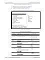
Conforms to the following standard(s) or other normative document(s):
EMC:
Safety:
EN 55022:1998 +
A1:2000, A2: 2003
Information technology equipment – Radio
disturbance characteristics – Limits and
methods of measurement.
EN 55024: 1998 +
A1:2001, A2:2003
Information technology equipment –
Immunity characteristics – Limits and
methods of measurement.
EN 60950-1:2001 +
A11:2004
Information technology equipment – Safety
– Part 1: General requirements
Supplementary Information:
The product herewith complies with the requirements of the EMC Directive 2004/108/EC, the
Low Voltage Directive 2006/95/EC and the R&TTE Directive 99/5/EC for wired equipment. The
product was tested in a typical configuration.
Tel Aviv, 14 January 2008
Haim Karshen
VP Quality
European Contact: RAD Data
Ottobrunn-Riemerling, Germany
Communications
GmbH,
Otto-Hahn-Str.
28-30,
85521
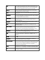
Glossary
Address
A coded representation of the origin or destination of data.
Agent
In SNMP, this refers to the managed system.
Analog
A continuous wave or signal (such as human voice).
ANSI
American National Standards Institute.
AWG
The American Wire Gauge System, which specifies wire width.
Balanced
A transmission line in which voltages on the two conductors are
equal in magnitude, but opposite in polarity, with respect to
ground.
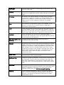
Bandwidth
The range of frequencies passing through a given circuit. The
greater the bandwidth, the more information can be sent through
the circuit in a given amount of time.
Baud
Unit of signaling speed equivalent to the number of discrete
conditions or events per second. If each signal event represents
only one bit condition, baud rate equals bps (bits per second).
Bit
The smallest unit of information in a binary system. Represents
either a one or zero (“1” or “0”).
Bit
Interleaving/Multiplexing
A process used in time division multiplexing where individual bits
from different lower speed channel sources are combined (one bit
from one channel at a time) into one continuous higher speed bit
stream.
bps (Bits Per Second)
A measure of data transmission rate in serial transmission.
Bridge
A device interconnecting local area networks at the OSI data link
layer, filtering and forwarding frames according to media access
control (MAC) addresses.
Buffer
A storage device. Commonly used to compensate for differences
in data rates or event timing when transmitting from one device to
another. Also used to remove jitter.
Bus
A transmission path or channel. A bus is typically an electrical
connection with one or more conductors, where all attached
devices receive all transmissions at the same time.
Byte
A group of bits (normally 8 bits in length).
Carrier
A continuous signal at a fixed frequency that is capable of being
modulated with a second (information carrying) signal.
Cell
The 53-byte basic information unit within an ATM network. The
user traffic is segmented into cells at the source and reassembled
at the destination. An ATM cell consists of a 5-byte ATM header
and a 48-byte ATM payload, which contains the user data.
Channel
A path for electrical transmission between two or more points.
Also called a link, line, circuit or facility.
Clock
A term for the source(s) of timing signals used in synchronous
transmission.
Compression
Any of several techniques that reduce the number of bits required
to represent information in data transmission or storage, thereby
conserving bandwidth and/or memory.
Concentrator
Device that serves as a wiring hub in a star-topology network.
Sometimes refers to a device containing multiple modules of
network equipment.
Congestion
A state in which the network is overloaded and starts to discard
user data (frames, cells or packets).
Data
Information represented in digital form, including voice, text,
facsimile and video.
Data Link Layer
Layer 2 of the OSI model. The entity, which establishes, maintains,
and releases data-link connections between elements in a
network. Layer 2 is concerned with the transmission of units of
information, or frames, and associated error checking.
dB (Decibel)
A unit used to measure relative increase or decrease in power,
voltage or current, using a logarithmic scale.
dBm
A measure of power in communications: the decibel in reference
to one milliwatt (0 dBm = 1 milliwatt and -30 dBm = .001
milliwatt).
Decibel
See dB.
Diagnostics
The detection and isolation of a malfunction or mistake in a
communications device, network or system.
Differential Delay
Differential delay is caused when traffic is split over different lines
that may traverse shorter and longer paths. Products like the RAD
IMX-2T1/E1 inverse multiplexer compensate for any differential
delay (up to 64 msec) between the T1 lines, to properly
reconstruct the original stream.
Digital
The binary (“1” or “0”) output of a computer or terminal. In data
communications, an alternating, non-continuous (pulsating) signal.
E3
The European standard for high speed digital transmission,
operating at 34 Mbps.
Encapsulation
Encapsulating data is a technique used by layered protocols in
which a low level protocol accepts a message from a higher level
protocol, then places it in the data portion of the lower-level
frame. The logistics of encapsulation require that packets traveling
over a physical network contain a sequence of headers.
Ethernet
A local area network (LAN) technology which has extended into
the wide area networks. Ethernet operates at many speeds,
including data rates of 10 Mbps (Ethernet), 100 Mbps (Fast
Ethernet), 1,000 Mbps (Gigabit Ethernet), 10 Gbps, 40 Gbps, and
100 Gbps.
Ethernet OAM
Ethernet operation, administration and maintenance (OAM) are a
set of standardized protocols for measuring and controlling
network performance. There are two layers of Ethernet OAM:
Service OAM (provides end-to-end connectivity fault management
per customer service instance, even in multi-operator networks)
and Link or Segment OAM (detailed monitoring and
troubleshooting of an individual physical or emulated link).
Flow Control
A congestion control mechanism that results in an ATM system
implementing flow control.
Frame
A logical grouping of information sent as a link-layer unit over a
transmission medium. The terms packet, datagram, segment, and
message are also used to describe logical information groupings.
Framing
At the physical and data link layers of the OSI model, bits are fit
into units called frames. Frames contain source and destination
information, flags to designate the start and end of the frame,
plus information about the integrity of the frame. All other
information, such as network protocols and the actual payload of
data, is encapsulated in a packet, which is encapsulated in the
frame.
Full Duplex
A circuit or device permitting transmission in two directions
(sending and receiving) at the same time.
FXO (Foreign Exchange
Office)
A voice interface, emulating a PBX extension, as it appears to the
CO (Central Office) for connecting a PBX extension to a
multiplexer.
FXS (Foreign Exchange
Subscriber)
A voice interface, emulating the extension interface of a PBX (or
subscriber interface of a CO) for connecting a regular telephone
set to a multiplexer.
Gateway
Gateways are points of entrance and exit from a communications
network. Viewed as a physical entity, a gateway is that node that
translates between two otherwise incompatible networks or
network segments. Gateways perform code and protocol
conversion to facilitate traffic between data highways of differing
architecture.
Grooming
In telecommunications, the process of separating and segregating
channels by combing, such that the broadest channel possible can
be assembled and sent across the longest practical link. The aim is
to minimize de-multiplexing traffic and reshuffling it electrically.
Half Duplex
A circuit or device capable of transmitting in two directions, but
not at the same time.
Interface
A shared boundary, defined by common physical interconnection
characteristics, signal characteristics, and meanings of exchanged
signals.
IP Address
Also known as an Internet address. A unique string of numbers
that identifies a computer or device on a TCP/IP network. The
format of an IP address is a 32-bit numeric address written as four
numbers from 0 to 255, separated by periods (for example,
1.0.255.123).
Jitter
The deviation of a transmission signal in time or phase. It can
introduce errors and loss of synchronization in high speed
synchronous communications.
Laser
A device that transmits an extremely narrow and coherent beam
of electromagnetic energy in the visible light spectrum. Used as a
light source for fiber optic transmission (generally more expensive,
shorter lived, single mode only, for greater distances than LED).
Loopback
A type of diagnostic test in which the transmitted signal is
returned to the sending device after passing through all or part of
a communications link or network.
MAN (Metropolitan Area
Network)
A network that provides regional connectivity within a
metropolitan area (such as a city).
Manager
An application that receives Simple Network Management Protocol
(SNMP) information from an agent. An agent and manager share a
database of information, called the Management Information Base
(MIB). An agent can use a message called a traps-PDU to send
unsolicited information to the manager. A manager that uses the
RADview MIB can query the RAD device, set parameters, sound
alarms when certain conditions appear, and perform other
administrative tasks.
Master Clock
The source of timing signals (or the signals themselves) that all
network stations use for synchronization.
Multimode Fiber
A fiber with a large core diameter; 50-200 microns compared with
the wavelength of light. It therefore propagates more than one
mode. With multimode fiber, light traverses multiple paths, some
longer than others. This leads to dispersion, which reduces optical
range.
Multiplexer
At one end of a communications link, a device that combines
several lower speed transmission channels into a single high speed
channel. A multiplexer at the other end reverses the process.
Sometimes called a mux. See Bit Interleaving/Multiplexing.
Network
(1) An interconnected group of nodes. (2) A series of points,
nodes, or stations connected by communications channels; the
collection of equipment through which connections are made
between data stations.
Node
A point of interconnection to a network.
Packet
An ordered group of data and control signals transmitted through
a network, as a subset of a larger message.
parameters
Parameters are often called arguments, and the two words are
used interchangeably. However, some computer languages such as
C define argument to mean actual parameter (i.e., the value), and
parameter to mean formal parameter. In RAD CLI, parameter
means formal parameter, not value.
Payload
The 48-byte segment of the ATM cell containing user data. Any
adaptation of user data via the AAL will take place within the
payload.
Physical Layer
Layer 1 of the OSI model. The layer concerned with electrical,
mechanical, and handshaking procedures over the interface
connecting a device to the transmission medium.
Port
The physical interface to a computer or multiplexer, for connection
of terminals and modems.
prompt
One or more characters in a command line interface to indicate
that the computer is ready to accept typed input.
Protocol
A formal set of conventions governing the formatting and relative
timing of message exchange between two communicating
systems.
QoS (Quality of Service)
Refers to the capability of a network to provide better service to
selected network traffic over various technologies, including Frame
Relay, Asynchronous Transfer Mode (ATM), Ethernet and 802.1
networks.
Router
An interconnection device that connects individual LANs. Unlike
bridges, which logically connect at OSI Layer 2, routers provide
logical paths at OSI Layer 3. Like bridges, remote sites can be
connected using routers over dedicated or switched lines to create
WANs.
Serial Transmission
A common mode of transmission, where the character bits are
sent sequentially one at a time instead of in parallel.
Single Mode
Describing an optical wave-guide or fiber that is designed to
propagate light of only a single wavelength (typically 5-10 microns
in diameter).
Space
In telecommunications, the absence of a signal. Equivalent to a
binary 0.
Sync
See Synchronous Transmission.
Synchronous
Transmission
Transmission in which data bits are sent at a fixed rate, with the
transmitter and receiver synchronized.
T1
A digital transmission link with a capacity of 1.544 Mbps used in
North America. Typically channelized into 24 DS0s, each capable of
carrying a single voice conversation or data stream. Uses two pairs
of twisted pair wires.
T3
A digital transmission link with a capacity of 45 Mbps, or 28 T1
lines.
Telnet
The virtual terminal protocol in the Internet suite of protocols. It
lets users on one host access another host and work as terminal
users of that remote host. Instead of dialing into the computer,
the user connects to it over the Internet using Telnet. When
issuing a Telnet session, it connects to the Telnet host and logs in.
The connection enables the user to work with the remote machine
as though a terminal was connected to it.
Throughput
The amount of information transferred through the network
between two users in a given period, usually measured in the
number of packets per second (pps).
Timeslot
A portion of a serial multiplex of timeslot information dedicated to
a single channel. In E1 and T1, one timeslot typically represents
one 64 kbps channel.
VLAN-Aware
A device that is doing the Layer 2 bridging according to the VLAN
tag in addition to the standard bridging parameters. A VLAN-aware
device will not strip or add any VLAN header.
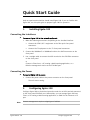
Quick Start Guide
Only an experienced technician should install Egate-100. If you are familiar with
Egate-100, use this quick guide to prepare Egate-100 for operation.
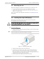
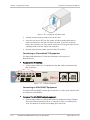
1.
Installing Egate-100
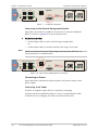
Connecting the Interfaces
³
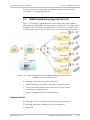
To connect Egate-100 to the network equipment:
1. Make the following connections, depending on the installed interface:
Connect the STM-1/OC-3 equipment to the fiber optic front panel
connectors.
Connect the T3 equipment to the T3 front panel connectors.
2. Connect the 1000BaseT or 1000BaseSx LAN to the DATA connector on the
front panel.
3. Use a straight cable to connect the ASCII terminal to the CONTROL connector
on the front panel
or
Connect a Telnet host, a PC running a Web-browsing application, or a
RADview management station to the ETH MNG port.
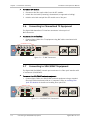
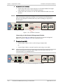
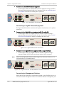
Connecting the Power
³
To connect Egate-100 to power:
•
Connect the power cable to the power connector on the front panel.
The unit starts running.
2.
Configuring Egate-100
Configure Egate-100 to the desired operation mode via an ASCII terminal connected
to the front panel CONTROL port. Alternatively, you can manage Egate-100 over
Telnet, a PC running a Web browsing application, or SNMP via the Ethernet or E3
port.
Note
Egate-100 Ver. 4.0
Remote management requires assigning an IP address
Configuring Egate-100
1
Quick Start Guide
Installation and Operation Manual
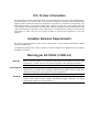
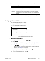
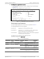
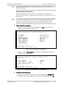
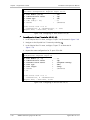
Starting a Terminal Session for the First Time
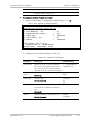
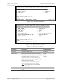
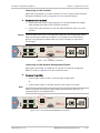
³
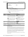
To start a terminal configuration session:
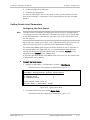
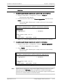
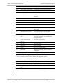
1. Connect an ASCII terminal to the CONTROL port on the front panel. The
default settings are as follows:
Baud Rate: 115,200 bps
Data Bits: 8
Parity: None
Stop Bits: 1
Flow Control: None.
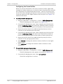
2. To optimize the view of the system menus, do the following:
Set the terminal emulator to VT100.
If you are using HyperTerminal, set the terminal mode to the 132-column
mode.
3. Power up Egate-100 and verify that the PWR LED on the front panel is on.
4. Verify the unit's correct startup by observing one of the following:
From the ASCII terminal verify that the Self-Test was successfully
completed
Check the ALM LED on the front panel of the unit:
Off – No alarms
On – Device alarm.
5. If the ALM LED is on, check the physical connections.
6. Press any key to display the Login screen.
7. Enter the user name and the password and proceed with the management
session.
Note
The default user names are su and user. The default password is 1234. Only su
has permission to modify configuration parameters and download new software
versions.
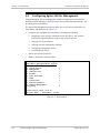
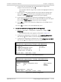
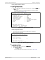
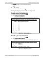
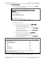
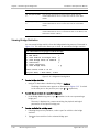
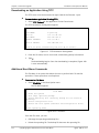
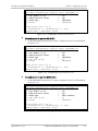
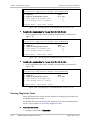
Configuring Basic Parameters
The Quick Setup menu allows you to configure mandatory elements. For
additional information on parameters and the menus, refer to Chapter 4.
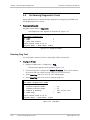
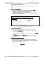
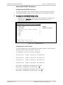
Configuration via the Quick Setup Menu
³
To configure the required parameters using the Quick Setup menu:
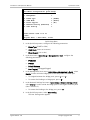
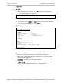
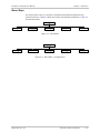
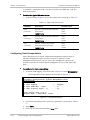
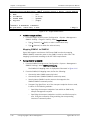
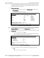
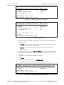
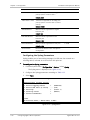
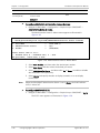
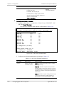
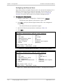
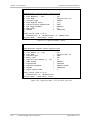
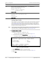
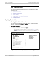
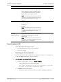
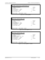
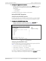
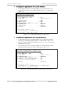
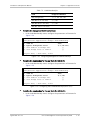
1. Navigate to Main Menu > Configuration > Quick Setup.
The Quick Setup appears as illustrated below.
2
Configuring Egate-100
Egate-100 Ver. 4.0
Installation and Operation Manual
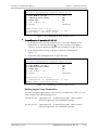
Quick Start Guide
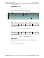
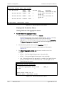
Egate-100
Main Menu> Configuration> Quick Setup
1.
2.
3.
4.
5.
6.
Management
Frame Type
VLAN Mode
Flows Support
Network Setting (Ethernet)
User Setting
>
> (SONET)
> (Aware)
> (No)
>
>
>
Please select item <1 to 5>
S-Save
ESC-prev.menu; !-main menu; &-exit
Quick Setup Menu
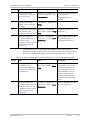
2. In the Quick Setup menu, configure the following parameters:
Frame Type (SONET or SDH)
VLAN Mode (Aware or Unaware)
Flows Support (Yes or No)
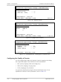
3. In the Host menu (Quick Setup > Management > Host), configure the
following parameters:
IP Address
IP Mask
Default Gateway
Host Tagging (Untagged/Tagged)
4. In the Management Ports menu (Quick Setup > Management > Ports), select
Bind to in order to bind a bridge port to the Host port or ETH-MNG port.
To navigate between the bridge ports, press <F> or <B>.
To remove the binding to a bridge port, press <R>.
5. In the Network Settings Port menu (Quick Setup > Network Setting > Ports),
select Bind to in order to bind the bridge ports to the Gigabit Ethernet ports
(Gbe-1 and Gbe-2).
To remove the binding to the bridge port, press <R>.
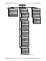
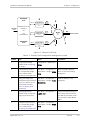
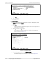
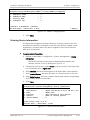
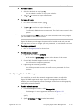
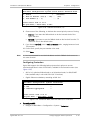
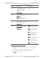
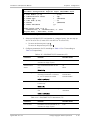
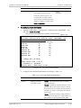
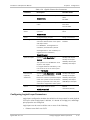
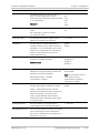
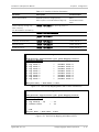
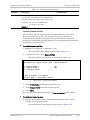
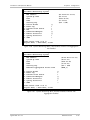
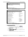
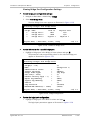
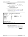
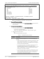
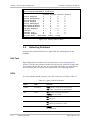
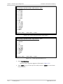
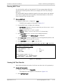
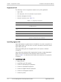
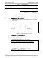
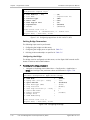
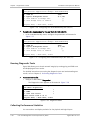
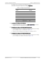
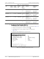
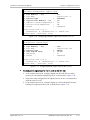
6. In the Quick Setup menu, select User Setting.
The User Setting menu appears.
Egate-100 Ver. 4.0
Configuring Egate-100
3
Quick Start Guide
Installation and Operation Manual
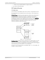
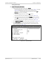
Egate-100
Main Menu> Configuration> Quick Setup> User Setting
1.
2.
3.
4.
5.
6.
7.
8.
9.
10.
11.
12.
13.
14.
15.
16.
17.
18.
Bridge Port Number [1 - 130]
Port Name
Protocol Type
Physical Port Number[1 - 63]
Frame Type
HDLC Flags[1-7]
Administrative Status
Queue Profile Name
Ingress Filtering
Accept Frame Types
Port VID >
Default Priority Tag
Replace Priority
Egress Tag Handling
Ingress Tag Handling
Loop Detection
Link OAM (802.3ah)
Maximum MAC Address[1 - 64000]
VLAN ID
...(3)
...(Bridge Port 3)
> (HDLC)
> (1)
> (Unframed)
> (1)
> (Up)
> ()
> (Enabled)
> (Tag only
...(1)
...(0)
> (No)
> (None)
> (None)
> (Enable)
> (Disabled)
...(64000)
...(0)
>
Please select item <1 to 6>
F – Fwd Port; B – Backward Port; R – Remove Port; A – Add Port
ESC-prev.menu; !-main menu; &-exit
Quick Setup User Setting Menu
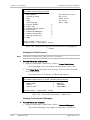
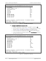
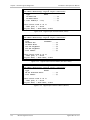
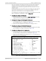
7. For each physical port that you wish to configure and/or bind to a bridge
port, press <A> and configure the following parameters:
4
Protocol Type. HDLC, PPP over HDLC for multiple E1/T1, or MLPPP for the
bundle that is bound to the PPP logical port, or GFP multi (LCAS) for
multiple E1/T1 ports
Physical Port Number. One of the 63/84 physical E1/T1 ports
Frame Type. Framing mode, Unframed/CRC-4/no CRC-4 for E1,
Unframed/ESF/D4 for T1
HDLC Flags. 1-7. The flags before and after an HDLC frame indicate the
start and end of the frame
Administrative Status. Enabled (Up) or disabled (Down)
Queue Profile Name. Name allocated to the queue profile
Ingress Filtering. Enabled or disabled
Accept Frame Types. All or Tag only
Port VID
Configuring Egate-100
Egate-100 Ver. 4.0
Installation and Operation Manual
Quick Start Guide
Default Priority Tag
Replace Priority Tag. Yes or No
Egress Tag Handling. None, Stripping, Stacking
Ingress Tag Handling. None, Stripping, Stacking
Loop Detection. Disabled or Enabled
Link OAM (802.3ah). Disabled or Enabled
Maximum MAC Adress. 1 – 64000
VLAN ID
Active Timeslots for framed physical ports only (1-31 or a list of values
for E1, 1-24 for a list of values for T1).
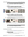
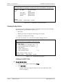
Configuration using Standard Menus
This section describes how to configure the required parameters using the full
menu structure.
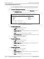
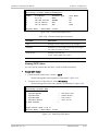
³
To configure the host parameters:
•
³
³
IP Mask
Default Gateway.
In the Encapsulation menu (Main > Configuration > System > Management
> Host> Encapsulation), configure the following parameters:
Host Tagging (untagged/tagged)
Host VLAN ID (for tagged only)
Host VLAN Priority (for tagged only).
In the Ethernet menu (Main > Configuration > Physical Layer > Ethernet),
press <F> or <B> to select the Gigabit Ethernet port under Port, and then
configure the following parameters:
Alarms: Specify whether to mask or unmask the alarms
Autonegotiation: Enable or disable autonegotiation mode.
The Autonegotiation option is only available for electrical interfaces, not for
optical interfaces.
To configure STM-1/OC-3 interfaces:
•
Egate-100 Ver. 4.0
IP Address
To configure the Ethernet interfaces:
•
Note
To configure the host encapsulation:
•
³
In the Host menu (Main > Configuration > System > Management
> Host), configure the following parameters:
In the SDH/SONET menu (Main > Configuration > Physical Layer
> SDH/SONET), configure the following parameters:
Configuring Egate-100
5
Quick Start Guide
³
Installation and Operation Manual
Frame Type: Specify whether mode of operation is SDH or SONET
Administrative Status: Specify whether the network port is to be used.
Tx Clock: Select the source of the system clock: Internal or Loopback
Timing.
Alarms: Specify whether to mask or unmask the alarms.
E1/T1: Specify the E1/T1 frame mode and port parameters.
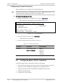
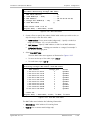
To configure channelized T3 interfaces:
1. In the T3 menu (Main > Configuration > Physical Layer > T3), configure the
following parameters:
Administrative Status: Specify whether the network port is to be used.
Tx Clock: Select the source of the system clock: Internal or Loopback
Timing.
Line Length: Specify long or short T3 line.
Alarms: Specify whether to mask or unmask the alarms.
2. Navigate to T1 (Main > Configuration > Physical Layer > T3 > T1) and
configure the mapped T1 channel parameters for each T3 port.
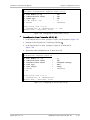
³
To configure logical ports:
•
³
In the Logical Ports menu (Main > Configuration > Logical Layer), define and
configure the required logical ports, including the selection of the protocol
(HDLC, PPP over HDLC, MLPPP, GFP, or VCG).
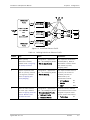
To configure bridge ports:
1. In the Bridge menu (Main > Configuration > Applications > Bridge), configure
the necessary bridge parameters:
VLAN Mode (VLAN-aware or VLAN-unaware): Specify whether bridge
operates in VLAN-aware or VLAN-unaware mode.
Aging Time: Specify how long to keep MAC table entry without erasing it,
if no frame is received with the MAC.
Split Horizon: Specify whether bridge operates with split horizon feature,
to prevent switching packets between bridge ports bound to logical ports
VLAN Ethertype: Specify value used to identify and manipulate VLAN
frames
Loop Detection: Specify whether loop detection is enabled.
2. In the Bridge Port menu (Main > Configuration > Applications > Bridge>
Bridge Ports), define the relevant bridge ports.
³
To enable Gigabit Ethernet port redundancy:
•
Note
6
In the Ethernet aggregation menu (Main > Configuration > System >
Protection > Ethernet Aggregation), enable Ethernet Aggregation.
To enable Ethernet aggregation, both Gigabit Ethernet links must be set to Full
Duplex mode at the same line speed, and autonegotiation must be enabled.
Configuring Egate-100
Egate-100 Ver. 4.0
Contents
Chapter 1. Introduction
1.1
1.2
1.3
Overview.................................................................................................................... 1-1
Product Options...................................................................................................... 1-2
Gigabit Ethernet Port Options............................................................................. 1-2
Uplink Options ................................................................................................... 1-2
STM-1/OC-3 Port Options ................................................................................... 1-2
T3 Port Options.................................................................................................. 1-2
Single/Dual Power Supply ................................................................................... 1-2
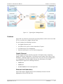
Applications ............................................................................................................ 1-2
Features ................................................................................................................. 1-3
Gigabit Ethernet ................................................................................................. 1-3
Ethernet Link Redundancy .................................................................................. 1-3
STM-1/OC-3 ....................................................................................................... 1-4
STM-1/OC-3 APS ................................................................................................ 1-4
Ethernet over E1/T1 Encapsulation ..................................................................... 1-4
Bridge ................................................................................................................ 1-4
Flows ................................................................................................................. 1-5
Ethernet OAM .................................................................................................... 1-5
Simple Network Time Protocol ............................................................................ 1-6
Management ...................................................................................................... 1-6
Diagnostic Tools ................................................................................................. 1-6
Statistics ............................................................................................................ 1-6
Alarms ............................................................................................................... 1-6
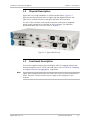
Physical Description ................................................................................................... 1-7
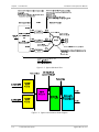
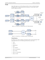
Functional Description................................................................................................ 1-7
STM-1/OC-3 Mapping .............................................................................................. 1-9
Gigabit Ethernet Link Aggregation ......................................................................... 1-10
Bridge................................................................................................................... 1-11
VLAN-Aware Mode ........................................................................................... 1-11
VLAN-Unaware Mode........................................................................................ 1-15
VLAN Ethertype ................................................................................................ 1-16
Split Horizon .................................................................................................... 1-16
Flows.................................................................................................................... 1-17
Classification .................................................................................................... 1-17
Policing and Bandwidth Profiles ........................................................................ 1-18
Queue Management ............................................................................................. 1-18
Quality of Service.................................................................................................. 1-18
IP Precedence / DSCP ....................................................................................... 1-19
VLAN Priority .................................................................................................... 1-19
Flooding ........................................................................................................... 1-20
Encapsulation ....................................................................................................... 1-20
GFP .................................................................................................................. 1-20
GFP Single ........................................................................................................ 1-20
GFP VCAT LCAS ................................................................................................. 1-20
GFP Technical Overview .................................................................................... 1-21
HDLC................................................................................................................ 1-24
PPP/BCP ........................................................................................................... 1-24
Multilink PPP .................................................................................................... 1-25
Timing .................................................................................................................. 1-25
Egate-100 Ver. 4.0B
i
Table of Contents
1.4
Installation and Operation Manual
Buffer Management .............................................................................................. 1-26
Management ........................................................................................................ 1-26
Inband Management ........................................................................................ 1-26
Out-of-Band Management ................................................................................ 1-26
Security ........................................................................................................... 1-27
Management Access......................................................................................... 1-27
Loop Detection ..................................................................................................... 1-28
Diagnostics ........................................................................................................... 1-29
Statistics Collection............................................................................................... 1-29
Configuration Reset .............................................................................................. 1-29
Technical Specifications............................................................................................ 1-30
Chapter 2. Installation and Setup
2.1
2.2
2.3
2.4
2.5
2.6
2.7
2.8
2.9
Site Requirements and Prerequisites .......................................................................... 2-1
Package Contents ...................................................................................................... 2-2
Required Equipment ................................................................................................... 2-2
Mounting the Unit ...................................................................................................... 2-3
Installing Fiber Optic SFP Modules .............................................................................. 2-3
Connecting to Channelized T3 Equipment ................................................................... 2-4
Connecting to SDH/SONET Equipment ........................................................................ 2-4
Connecting to Gigabit Ethernet Equipment ................................................................. 2-5
Connecting to Management Stations .......................................................................... 2-5
Connecting to the Terminal ..................................................................................... 2-5
Connecting to the Network Management Station .................................................... 2-6
2.10 Connecting to Power .................................................................................................. 2-7
Connecting to AC Power.......................................................................................... 2-7
Connecting to DC Power ......................................................................................... 2-7
Replacing AC/DC Hot-Swappable Power Supply Unit................................................. 2-7
Chapter 3. Operation
3.1
3.2
3.3
3.4
3.5
3.6
Turning On the Unit ................................................................................................... 3-1
Indicators .................................................................................................................. 3-1
Default Settings ......................................................................................................... 3-2
Configuration and Management Alternatives .............................................................. 3-5
Working with Terminal ............................................................................................ 3-5
Logging In .......................................................................................................... 3-6
ASCII Screen Format ........................................................................................... 3-6
Working with the Web-Based Management Application ........................................... 3-7
Requirements for Web-Based Management ........................................................ 3-7
Logging In .......................................................................................................... 3-7
Navigating the Web Menus ................................................................................. 3-8
Overview of Menu Operations .................................................................................... 3-8
Main Menu Paths .................................................................................................... 3-8
Principles of Navigation........................................................................................... 3-9
Hot Keys ................................................................................................................ 3-9
Menu Maps ........................................................................................................... 3-11
Turning Off the Unit ................................................................................................. 3-17
Chapter 4. Configuration
4.1
ii
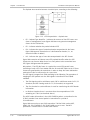
Services ..................................................................................................................... 4-2
Ethernet Management Traffic .................................................................................. 4-2
E-LAN Services ........................................................................................................ 4-4
Egate-100 Ver. 4.0B
Installation and Operation Manual
4.2
4.3
4.4
Table of Contents
E-LAN Services with Quality of Services ................................................................... 4-6
Configuring Egate-100 for Management ..................................................................... 4-8
Defining Host Parameters ....................................................................................... 4-9
Configuring Host Encapsulation ............................................................................. 4-10
Configuring SNMPv3 .............................................................................................. 4-11
Configuring the SNMP Engine ID ....................................................................... 4-11
Enabling SNMPv3 .............................................................................................. 4-12
Adding SNMPv3 Users ...................................................................................... 4-13
Adding SNMPv3 Notification Entries .................................................................. 4-14
Assigning Traps ................................................................................................ 4-15
Configuring Target Parameters ......................................................................... 4-16
Configuring Target Address .............................................................................. 4-17
Mapping SNMPv1 to SNMPv3 ............................................................................ 4-18
Entering Device Information .................................................................................. 4-19
Controlling Management Access ............................................................................ 4-20
Defining Access Policy ...................................................................................... 4-21
Configuring User Access ........................................................................................ 4-21
Configuring Network Managers ............................................................................. 4-23
Configuring Radius Server Parameters ................................................................... 4-24
Configuring Terminal Parameters ........................................................................... 4-26
Configuring Egate-100 for Operation........................................................................ 4-26
Setting Device-Level Parameters ........................................................................... 4-27
Configuring the Clock Source ............................................................................ 4-27
Configuring Protection ..................................................................................... 4-29
Configuring the Frame Buffers .......................................................................... 4-32
Configuring the Syslog Parameters ................................................................... 4-34
Setting Physical Layer Parameters ......................................................................... 4-36
Configuring the SDH/SONET Ports..................................................................... 4-36
Configuring the Channelized T3 Ports ............................................................... 4-51
Configuring the Ethernet Ports ......................................................................... 4-54
Configuring Logical Layer Parameters .................................................................... 4-55
Configuring Logical Ports .................................................................................. 4-56
Configuring the Service Virtual Interface (SVI) ................................................... 4-62
Configuring the Bridge .......................................................................................... 4-63
Configuring the MAC Table ............................................................................... 4-66
Configuring the Bridge Ports ............................................................................. 4-67
Configuring VLAN Membership .......................................................................... 4-70
Configuring the Quality of Service ......................................................................... 4-72
Configuring QoS Priority Mapping ..................................................................... 4-74
Configuring Unknown Unicast, Multicast, and Broadcast Priorities ..................... 4-76
Configuring Flows ............................................................................................. 4-80
Additional Tasks ....................................................................................................... 4-84
Displaying Device Status ....................................................................................... 4-84
Viewing System Status Information .................................................................. 4-84
Viewing the Clock Sources ................................................................................ 4-86
Viewing the Connected Managers ..................................................................... 4-86
Viewing SNTP Status......................................................................................... 4-87
Viewing Link Protection Status ......................................................................... 4-88
Viewing Physical Layer Status ........................................................................... 4-92
Viewing OAM Status ......................................................................................... 4-98
Viewing Bridge Status ......................................................................................... 4-100
Viewing the MAC Table ................................................................................... 4-100
Viewing the Mapping between VLANs and Bridge Ports ................................... 4-102
Viewing Bridge Port Configuration Settings ..................................................... 4-103
Egate-100 Ver. 4.0B
iii
Table of Contents
Installation and Operation Manual
Displaying Flow Information ................................................................................ 4-104
Viewing Inventory ............................................................................................... 4-107
Configuring Date, Time, and SNTP Parameters ..................................................... 4-108
Resetting Egate-100 ........................................................................................... 4-111
Resetting to Factory Defaults ......................................................................... 4-111
Resetting the Unit .......................................................................................... 4-112
Chapter 5. Monitoring and Diagnostics
5.1
5.2
5.3
5.4
5.5
5.6
5.7
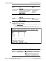
Monitoring Performance ............................................................................................. 5-1
Viewing Ethernet Statistics ...................................................................................... 5-1
Viewing SDH/SONET Statistics ................................................................................. 5-2
Viewing Logical Layer Statistics ............................................................................... 5-7
Viewing Bridge Statistics ....................................................................................... 5-10
Viewing Radius Statistics ....................................................................................... 5-11
Detecting Problems .................................................................................................. 5-12
Self Test ............................................................................................................... 5-12
LEDs ..................................................................................................................... 5-12
Alarms and Events ................................................................................................ 5-13
Traps .................................................................................................................... 5-21
Statistic Counters ................................................................................................. 5-22
Handling Events ....................................................................................................... 5-22
Displaying Events .................................................................................................. 5-22
Displaying Alarms.................................................................................................. 5-25
Masking Alarms ..................................................................................................... 5-26
Troubleshooting ....................................................................................................... 5-26
Performing Diagnostics Tests ................................................................................... 5-28
Running Ping Test ................................................................................................. 5-28
Running BERT Test ................................................................................................ 5-29
Viewing Self Test Results ...................................................................................... 5-29
Frequently Asked Questions ..................................................................................... 5-30
Technical Support .................................................................................................... 5-30
Chapter 6. Software Upgrade
6.1
6.2
6.3
6.4
6.5
6.6
6.7
iv
Compatibility Requirements ........................................................................................ 6-1
Impact ....................................................................................................................... 6-2
Software Upgrade Options ......................................................................................... 6-2
Prerequisites .............................................................................................................. 6-2
Software Files ......................................................................................................... 6-2
System Requirements ............................................................................................. 6-2
Upgrading Egate-100 Software via the File Utilities Menu ........................................... 6-3
Transferring Software Files via TFTP ........................................................................ 6-3
Transferring Software Files via X-Modem ................................................................. 6-4
Saving/Deleting the Current Configuration as Default .............................................. 6-4
Additional Utilities Menu Commands ....................................................................... 6-5
Upgrading Egate-100 Software via the Boot Menu...................................................... 6-5
Accessing the Boot Menu ........................................................................................ 6-6
Downloading an Application Using the XMODEM Protocol ........................................ 6-7
Downloading an Application Using TFTP .................................................................. 6-8
Additional Boot Menu Commands............................................................................ 6-8
Verifying Upgrade Results .......................................................................................... 6-9
Egate-100 Ver. 4.0B
Installation and Operation Manual
Table of Contents
Chapter 7. Application Tutorial
7.1
7.2
7.3
User and Management Traffic Separated by VLAN....................................................... 7-1
Equipment List ........................................................................................................ 7-2
Installing Egate-100 ................................................................................................ 7-2
Mounting the Unit .............................................................................................. 7-3
Installing Fiber Optic SFP Modules....................................................................... 7-3
Connecting to Channelized T3 Equipment ........................................................... 7-4
Connecting to SDH/SONET Equipment ................................................................ 7-4
Connecting to Gigabit Ethernet Equipment ......................................................... 7-4
Connecting to Management Stations .................................................................. 7-5
Connecting to Power .......................................................................................... 7-6
Configuring Egate-100 ............................................................................................ 7-7
Setting System Parameters................................................................................. 7-7
Setting Ethernet Parameters .............................................................................. 7-8
Setting SDH/SONET Parameters .......................................................................... 7-9
Setting Logical Layer Parameters ...................................................................... 7-11
Setting Bridge Parameters ................................................................................ 7-14
Running Diagnostic Tests ...................................................................................... 7-20
Collecting Performance Statistics .......................................................................... 7-20
IP DSLAM and WiMAX Backhauling over SDH/SONET .................................................. 7-22
Equipment List ...................................................................................................... 7-22
Installing Egate-100 .............................................................................................. 7-23
Mounting the Unit ............................................................................................ 7-23
Installing Fiber Optic SFP Modules..................................................................... 7-23
Connecting to Channelized T3 Equipment ......................................................... 7-24
Connecting to SDH/SONET Equipment .............................................................. 7-24
Connecting to Gigabit Ethernet Equipment ....................................................... 7-25
Connecting to Management Stations ................................................................ 7-25
Connecting to Power ........................................................................................ 7-27
Configuring the Egate-100 .................................................................................... 7-27
Setting System Parameters............................................................................... 7-28
Setting Ethernet Parameters ............................................................................ 7-29
Setting SDH/SONET Parameters ........................................................................ 7-29
Setting Logical Layer Parameters ...................................................................... 7-32
Setting Bridge Parameters ................................................................................ 7-34
Running Diagnostic Tests ...................................................................................... 7-37
Collecting Performance Statistics .......................................................................... 7-38
WiMAX Backhauling Opposite RICi-4T1 ...................................................................... 7-39
Equipment List ...................................................................................................... 7-39
Installing Egate-100 .............................................................................................. 7-40
Mounting the Unit ............................................................................................ 7-40
Installing Fiber Optic SFP Modules..................................................................... 7-40
Connecting to Channelized T3 Equipment ......................................................... 7-41
Connecting to SDH/SONET Equipment .............................................................. 7-41
Connecting to Gigabit Ethernet Equipment ....................................................... 7-42
Connecting to Management Stations ................................................................ 7-42
Connecting to Power ........................................................................................ 7-44
Egate-100 Ver. 4.0B
v
Table of Contents
Installation and Operation Manual
Configuring Egate-100 .......................................................................................... 7-44
Setting System Parameters............................................................................... 7-45
Setting Ethernet Parameters ............................................................................ 7-46
Setting SDH/SONET Parameters ........................................................................ 7-47
Setting Logical Layer Parameters ...................................................................... 7-51
Setting Bridge Parameters ................................................................................ 7-56
Running Diagnostic Tests ...................................................................................... 7-60
Collecting Performance Statistics .......................................................................... 7-61
Appendix A. Connection Data
Appendix B. SDH/SONET Mapping
vi
Egate-100 Ver. 4.0B
Chapter 1
Introduction
1.1
Overview
Egate-100 is a Gigabit Ethernet over TDM aggregation gateway that combines
Ethernet traffic carried over PDH (E1/T1) into a Gigabit Ethernet MAN
(Metropolitan Area Network). Egate-100 can aggregate up to 126 remote LANs
over fractional E1/T1 or up to 42 links using standard bonding protocols.
The unit features next-generation Ethernet over PDH encapsulation and bonding
capabilities with support for standard protocols such as generic framing
procedure (GFP), virtual concatenation (VCAT), and link capacity adjustment
scheme (LCAS). The GFP, VCAT, and LCAS protocols allow service providers to
dynamically allocate bandwidth to their customers. By incorporating these
enhanced capabilities, Egate-100 enables higher user throughput, and offers the
following benefits:
•
Allows users to fully utilize their contracted bandwidth by ensuring low and
constant traffic overhead
•
Minimizes service disruptions in cases of link failures via hitless traffic
restoration
•
Enables high service resiliency for real-time applications by dramatically
reducing delays on the TDM connections
•
Ensures robust traffic delivery with automatic error correction and minimal
packet retransmissions
•
Enhances Ethernet over NG-PDH capabilities by supporting multiple NTUs in
up to 42 remote locations.
Full Layer 2 switching (bridge) between the Ethernet segments beyond the SDH
and Gigabit Ethernet networks is provisioned. The bridge supports VLAN-aware
and VLAN-unaware bridging modes, and can be used for VLAN-based Layer 2
VPNs.
Egate-100 also supports flow classification and policing for network ingress
traffic. Classification is supported per port that enables packet identifiers such as
VID, p-bit, DSCP and IP-precedence.
The unit includes two electrical or optical Gigabit Ethernet ports and, depending
on the interface option ordered, either a dual port to the SDH/SONET network or
three channelized T3 ports. The Gigabit Ethernet ports support link aggregation
according to IEEE 802.3ad requirements. The dual SDH/SONET ports support
unidirectional APS or 1+1 optimized bidirectional mode, as per ITU G.841 Annex B.
Egate-100 Ver. 4.0
Overview
1-1
Chapter 1 Introduction
Installation and Operation Manual
Egate-100 can be managed via Telnet and the Web-based management
application for inband configuration and management, as well as an ASCII
terminal for out-of-band management.
The unit is supplied as a compact standalone 1U high enclosure, with an optional
19-inch rack mounting kit.
Product Options
Gigabit Ethernet Port Options
The Gigabit Ethernet port versions are:
•
1000BaseSx, 850nm, LC (SFP) connector
•
1000BaseLx, 1310 nm, LC (SFP) connector
•
10/100/1000BaseT, RJ-45 connector.
Uplink Options
Egate-100 is equipped with two STM-1/OC-3 ports or three channelized T3
interfaces.
STM-1/OC-3 Port Options
The STM-1/OC-3 port versions are:
•
Single mode, 1310 nm short haul per G.957-S1.1, LC (SFP) connector
•
Single mode, 1310 nm long haul per G.957-L1.1, LC (SFP) connector
•
Multi mode, 1310 nm, LC (SFP) connector.
T3 Port Options
Egate-100 has three channelized T3 ports. Each T3 port has 28 T1s mapped to
the T3 interface via M13 multiplexer.
Single/Dual Power Supply
Single or dual power supply versions are available.
Note
A combination of DC and AC power supplies on the same unit is not allowed.
Applications
Figure 1-1 illustrates a typical application, where Egate-100 supports three
remote sites using different user VLANs (CPEs using tag stacking) and an
additional host VLAN shared by the three CPEs for secured management traffic.
See Chapter 7 for information on implementing this application.
1-2
Overview
Egate-100 Ver. 4.0
Installation and Operation Manual
Chapter 1 Introduction
Figure 1-1. Typical Egate-100 Application
Features
Egate-100 is an Ethernet concentrator grooming Ethernet traffic carried over PDH
(E1/T1) over SDH into a Gigabit Ethernet LAN.
The unit includes the following interfaces:
•
Two Gigabit Ethernet ports
•
Two STM-1/OC-3c ports or three channelized T3 ports
•
Fast Ethernet port for management
•
Terminal control port for out-of-band management.
Gigabit Ethernet
The two Gigabit Ethernet interfaces operate in full duplex mode, supporting
regular size frames (1600 bytes). The Ethernet ports support flow control as per
IEEE 802.3, including support for pause frames. The ports can act as bridge ports
or be aggregated to provide Gigabit Ethernet link redundancy The Gigabit
Ethernet ports support the following interfaces:
•
1000BaseSx
•
1000BaseLx
•
10/100/1000BaseT with autonegotiation.
Ethernet Link Redundancy
Egate-100 supports Gigabit Ethernet link redundancy based on the link
aggregation protocol IEEE 802.3ad.
Egate-100 Ver. 4.0
Overview
1-3
Chapter 1 Introduction
Installation and Operation Manual
STM-1/OC-3
Egate-100 supports two channelized STM-1/OC-3 interfaces (with APS support)
for SDH mapping (E1s over VC-12 over VC4) or SONET mapping (T1s over VT1.5
over STS1 over STS3). Either port can be configured as the active port.
SDH/SONET mode is user-configurable. Jitter output and tolerance comply with
G.825 requirements.
STM-1/OC-3 APS
The option for APS (Automatic Protection Switching) between the two
STM-1/OC-3 ports is available, and can be configured for either unidirectional or
1+1 optimized bidirectional mode, as per ITU G.841 Annex B.
Ethernet over E1/T1 Encapsulation
Egate-100 allows you to map up to 63 E1 or 84 T1 channels into the
CH-STM-1/OC-3 interface using the four protocols listed below individually or in
combination:
•
GFP (G.8040) VCAT (G.7043) LCAS (G.7041): Up to 42 remote sites of
Ethernet over up to 16 E1/T1 links. Egate-100 can work opposite RAD’s
RICi-16 at the remote end to support a complete remote and central site
solution for Ethernet over n x E1/T1.
•
GFP (G.8040): Up to 63/84 remote sites of Ethernet over GFP. Ethernet is
mapped over framed E1/T1. For E1, the GFP frames are mapped into
16-frame multi-frame according to G.704. For T1, they are mapped into
24-frame 1544 kbps multi-frame.
•
MLPPP: Up to 42 remote sites of Ethernet over n x E1/T1, using MLPPP.
Ethernet can be mapped over up to 8 E1/T1 links. Egate-100 can work
opposite RAD’s RICi-4E1/T1 or RICi-8E1/8T1 at the remote end to support a
complete remote and central site solution for Ethernet over n x E1/T1.
•
PPP/BCP: Up to 126 remote sites of Ethernet over PPP/BCP (FCD-E1 and
FCD-IP compatible). Ethernet can be mapped over unframed E1/T1, or over
fractional E1/T1: n x 64, where n (number of timeslots) = 1–31 for E1 and
1–24 for T1.
•
HDLC: Up to 126 remote sites of Ethernet over RAD HDLC over E1/T1
(RICi-E1/T1, FCD-E1, and FCD-IP compatible). Ethernet can be mapped over
unframed E1/T1, or over fractional E1/T1: n x 64, where n (number of
timeslots) = 1–31 for E1 and 1–24 for T1.
Bridge
Egate-100 provides a bridging functionality between its bridge ports:
1-4
•
E1/T1 over SDH/SONET (Ethernet over E1/T1 or fractional E1/T1), or T1 over
T3
•
Gigabit Ethernet ports
•
Fast Ethernet management port
•
Internal host.
Overview
Egate-100 Ver. 4.0
Installation and Operation Manual
Chapter 1 Introduction
The internal bridge operates in VLAN-unaware or VLAN-aware modes (with or
without VLAN double tagging).
The VLAN-aware bridge mode allows you to create a subgroup of bridge ports
within the bridge. Each such subgroup is associated with a unique VLAN ID.
Frames can be forwarded only between bridge ports that are members of the
same VLAN, thus enabling a total separation between different VLAN users within
the same bridge.
In VLAN-unaware mode the bridge ignores VLAN tags and forwards frames
according to only their source and destination MAC addresses.
Flows
Egate-100 provides traffic flow classification and policing for Network ingress
traffic. Egate-100 supports up to 253 unidirectional flows originating from SVI
bound to GbE and heading towards the logical pot. Each flow is defined by a
classification profile.
Incoming traffic is classified and mapped according to port-based (all-in-one)
bundling or by port and CE VLAN-ID, VLAN priority, DSCP and IP precedence.
Operators can differentiate services using classification methods, police the
traffic and enforce SLA per service.
Classification
The Egate-100 classifier uses classification fields/rules per port. Up to 256
classification profiles/instances are supported.
For more information about flow classification, refer to Functional Description.
Policing and Bandwidth profiles
Policers can be applied per flow and operate according to the dual bucket
mechanism (CIR + CBS, EIR + EBS). Egate-100 supports up to 256 policers.
Ethernet OAM
The device provides OAM tools to monitor and troubleshoot an Ethernet network
and quickly detect failures in a single segment (link) according to IEEE 802.3ah for
remote management and remote fault indication, including remote terminal. The
OAM mechanism is useful for monitoring link operation.
The device supports OAM discovery, continuity check, and remote fault indication.
The discovery process enables you to observe the remote device MAC address,
capabilities, and vendor type.
The continuity check issues an alarm when there is no OAM connection with the
remote device. The remote fault indication issues an alarm when it receives one
of the following from the remote device:
Egate-100 Ver. 4.0
•
Link failure
•
Dying gasp
•
Critical event.
Overview
1-5
Chapter 1 Introduction
Installation and Operation Manual
Simple Network Time Protocol
The Simple Network Time Protocol (SNTP) provides the means of synchronizing all
managed elements across the network to a reliable clock source. The Egate-100
clock can be automatically synchronized to an accurate time from an NTP server
at user-selectable intervals.
Management
You can set up, control, and monitor Egate-100 using one of the following
methods:
•
•
Local and remote management via Gigabit Ethernet port or Fast Ethernet
management port
Local management via an ASCII terminal connected to the V.24 (RS-232) DCE
control port.
Web-based Management
Egate-100s Web-based element management system for remote device
configuration and maintenance is embedded in Egate-100 and provided at no
additional cost. The management system can be accessed from any standard
Web browser. For additional information, refer to Chapter 3.
Security
The following security protocols are provided by Egate-100 to ensure clientserver communication privacy and correct user authentication:
•
RADIUS (client authentication only)
•
SSLv3 for Web-based management application
•
SSHv2 for Secure Shell communication session
•
SNMPv3 (SNMPv1 is used if SNMPv3 is not enabled).
In addition, management access can be limited to only stations in the Manager
List.
Diagnostic Tools
Egate-100 supports ping tests, E1/T1 PRBS tests, and reviewing self-test results.
For additional information, refer to Chapter 5.
Statistics
The device provides statistics and counters capability for the various physical
interfaces, as well as at the level of logical port and bridge port. For additional
information, refer to Chapter 5.
Alarms
There is an active alarm and log file at the SDH/SONET, T3, Gigabit Ethernet, and
system levels. For additional information, refer to Chapter 5.
1-6
Overview
Egate-100 Ver. 4.0
Installation and Operation Manual
1.2
Chapter 1 Introduction
Physical Description
Egate-100 is a 1U high standalone or rack-mountable device. Figure 1-2
illustrates three-dimensional views of Egate-100 with Gigabit Ethernet and
STM-1/OC-3 network interfaces, and Egate-100 with 3xT3 interfaces.
The unit's LEDs, interface, and control connectors (and two hot-swappable
power-supply connectors) are located on the front panel. For additional
information about the unit's LEDs, refer to Chapter 3.
Figure 1-2. Egate-100 3D View
1.3
Functional Description
This section explains the data flow inside Egate-100. For mapping schemes and
backup mechanisms on OC-3/STM-1 and GbE ports, refer to STM-1/OC-3 Mapping
and Gigabit Ethernet Link Aggregation respectively.
Note
Egate-100 Ver. 4.0
Egate-100 is equipped with either two STM-1/OC-3 ports or three channelized T3
ports. Therefore, certain sections may not apply to the configuration you
ordered.
Functional Description
1-7
Chapter 1 Introduction
Installation and Operation Manual
Figure 1-3. Egate-100 Work Flow
Figure 1-4. Egate-100 Hardware Block Diagram
1-8
Functional Description
Egate-100 Ver. 4.0
Installation and Operation Manual
Chapter 1 Introduction
Incoming traffic from the Ethernet ports is processed by the Network processor,
which performs bridging, forwarding and QoS based queuing, which results in an
egress bridge to a logical port. The packets are marked with a bridge port ID and
forwarded over the high speed bus to the FPGA. The FPGA maps the packets of
each bridge port to the associated E1/T1 group according to the associated
encapsulation method.
Figure 1-3 illustrates the work flow and Figure 1-4 illustrates the corresponding
hardware blocks inside Egate-100.
The FPGA is responsible for the HDLC/GFP encapsulation including CRC calculation
and zero bit insertion. The FPGA then maps each of these flows into the right
bundle and forwards it over the TDM bus to the SDH/SONET mapper.
In the opposite direction, the same process takes place with the packet being
transferred to the Ethernet port. Local switching between two virtual ports is
possible.
In case of an MLPPP bundle (nxE1/T1 bundle), the network processor is
responsible for the implementation of the appropriate inverse multiplexer
scheme/buffer. In case of GFP and GFP bonding, the FPGA handles the GFP
encapsulation and bonding unlike the MLPPP case where the network processor
performs the bonding.
STM-1/OC-3 Mapping
The SDH/SONET port supports STM-1/OC-3 over optical interface. The optical
interface can be either single-mode short-haul according to G.957 S 1.1, single
mode long haul according to G.957 L 1.1, or multimode according to ANSI T1 646.
Two STM-1/OC-3 ports support APS, to ensure that one is available at all times.
Egate-100 operates in either SDH or SONET mode to support different framing
and mapping parameters.
Two mapping schemes are presented:
•
E1 over STM-1 (SDH path)
•
T1 over OC-3 (SONET path).
STM-1 Mapping
The following figure illustrates the mapping of E1s over SDH.
Figure 1-5. STM-1 / AU-4 / VC-4 / TUG-3s / TUG-2s / TU-12s / VC-12s /E1s
Egate-100 Ver. 4.0
Functional Description
1-9
Chapter 1 Introduction
Installation and Operation Manual
SONET Mapping
The following figure illustrates the mapping of T1s over SONET.
Figure 1-6. Low Order: OC-3 / STS-1 SPEs / VT Group / VT1.5s / T1s
Gigabit Ethernet Link Aggregation
The two Gigabit Ethernet ports can be configured to operate independently as
two separate Ethernet interfaces, or as a single Ethernet interface with link
aggregation mode in accordance with IEEE 802.3ad (without LACP). This mode
inherently provides redundancy: if one of the two Ethernet ports fails, the second
one takes over.
The two Gigabit Ethernet ports use link aggregation in accordance with
IEEE 802.3ad without LACP (Link Aggregation Control Protocol). In the virtual link
group only one link transmits at a time. If the transmitting link encounters an
error, Egate-100 switches to the redundant link in the group.
With link aggregation, the two Gigabit Ethernet ports serve as a single logical
interface. The two ports must be connected to the same switch/router and set to
the same speed and full duplex autonegotiation must be enabled. Figure 1-7
illustrates link aggregation mode.
Figure 1-7. Link Aggregation Mode
Failure of one of the links is detected by sensing the loss of valid signals at a
port, in which case the traffic is sent through the remaining port.
The equipment connected to the Gigabit Ethernet ports must support and be
configured for link aggregation according to 802.ad with LACP disabled:
•
Layer 2 switching networks – signal loss
As the two Gigabit Ethernet ports serve as a single logical interface, the learning
tables do not change as a result of the interface flip.
The switching time for Gigabit Ethernet optical interfaces is below 50 ms. For
1000BaseT, the switching time is below 1 second, limited by the longer loss of
signal detection for 1000BaseT technology.
Note
1-10
For Gigabit Ethernet redundancy to work properly when 802.3ad is enabled, both
Gigabit Ethernet ports must be set to full duplex mode at the same line speed,
and autonegotiation must be enabled.
Functional Description
Egate-100 Ver. 4.0
Installation and Operation Manual
Chapter 1 Introduction
Bridge
Egate-100 has a multiport bridge with up to two Ethernet bridge ports and up to
130 bridge ports over the CH-STM-1/OC-3 interface. The bridge supports two
modes of operation: VLAN-aware and VLAN-unaware.
VLAN-Aware Mode
This mode enables creation of subgroups of bridge ports within the bridge. Each
subgroup is defined per VLAN and is associated with a unique VLAN ID. Frames
with a specific VLAN ID can be forwarded only between bridge ports that are
members of the same VLAN, thus enabling a total separation between different
VLAN users within the same bridge.
The bridge features in VLAN-aware mode are:
•
Full VLAN-aware bridge as per 802.1Q
•
VLAN tag options:
Option for VLAN tag stacking (“double VLAN”) at bridge port ingress
Option for VLAN tag stacking (“double VLAN”) at bridge port egress
Option to copy/set VLAN priority tag at port ingress
Option for VLAN tag stripping at port egress
Option for VLAN tag stripping at bridge port ingress.
•
Learning and forwarding according to MAC address and VID
•
Learning of up to 64,000 MAC table entries (MAC-VID pairs)
•
Up to 1024 VLANs supported (out of the full VLAN range)
•
MAC learning limit – can be configured for each bridge port
•
Aging time – can be configured at the bridge level
•
MAC table viewing (learned MACs)
•
Optional loop detection
•
Ethernet OAM (802.3ah).
The mechanism of the VLAN-aware bridge can be described as five different
processes:
Egate-100 Ver. 4.0
•
Ingress – checks each frame entering the bridge to decide if and how this
frame should be passed on to the forwarding process
•
Learning – learns new MAC table entries (MAC only or MAC-VID pairs)
•
Aging – checks the forwarding MAC table periodically
•
Forwarding – decides to which bridge port/ports to forward the frame
•
Egress – selects the format of the transmitted frame at the output port, with
or without VLAN.
Functional Description
1-11
Chapter 1 Introduction
Installation and Operation Manual
Ingress Process
The ingress process is composed of three subprocesses: frame admission, ingress
filtering and PVID assignment to untagged/priority only tagged frames.
•
•
Frame admission – has two modes of operation (configurable per bridge):
Admit all frames – all frames arriving from the port are admitted and
proceed to the Ingress Filtering process.
Admit only VLAN-tagged frames – only VLAN-tagged frames are admitted
and allowed to proceed to the ingress filtering process. Untagged or
priority-only tagged frames are discarded.
Ingress filtering – configured per bridge, to one of the following modes:
Enabled – perform ingress filtering according to VID. This means that only
frames that share a VID assigned to this bridge port are admitted
Disabled – all frames are forwarded.
Only admitted frames that pass filtering are submitted to the learning and
forwarding processes. Table 1-1 summarizes the behavior of the ingress
process.
Table 1-1. Ingress Process
Frame Admission
Mode
Ingress Filtering Mode
Bridge Behavior
Admit all frames
Enabled
VLAN-tagged frames with a VLAN ID (or PVID for
untagged/priority tagged frames) that do not include
the bridge port in their VLAN member set are dropped
Disabled
All frames pass.
Enabled
VLAN-tagged frames with a VLAN ID that do not
include the bridge port in their member set are
dropped. Untagged/priority-tagged frames are
dropped.
Disabled
All VLAN-tagged frames pass.
Untagged/priority-tagged frames are dropped.
Admit VLAN-tagged
frames
•
PVID assignment – configurable per bridge port:
•
Default priority tag – configurable per bridge port:
1-12
In VLAN-aware mode, each received frame entering the bridge is
associated with a single VID. In cases where the received frame does not
contain a VLAN ID (i.e., untagged or priority-only tagged frames), a
specific PVID is assigned to the frame before it passes to the forwarding
process. This means that the untagged/priority tagged frames that have
passed the admission are tagged with PVID and proceed to the ingress
filtering process. Tagged frames are double-tagged with the PVID only if
tag stacking is enabled.
In VLAN-aware mode, each received frame entering the bridge is
associated with a single VLAN ID and priority. In cases where the received
frame does not contain a VLAN ID (i.e., untagged frames), a specific PVID
Functional Description
Egate-100 Ver. 4.0
Installation and Operation Manual
Chapter 1 Introduction
and default priority tag are assigned to the frame before it passes to the
forwarding process. If tag stacking is enabled, the user can select the
priority according to the received priority tag or the default priority tag.
•
Replace priority – configurable per bridge port:
•
Copy origin priority – configurable per bridge port:
•
When stacking is disabled in VLAN-aware mode, each received frame that
enters the bridge is tagged with VLAN ID and priority. The original priority
can be replaced with the default priority tag when this parameter is set
to Yes.
When stacking is enabled in VLAN-aware mode, each received frame that
enters the bridge is tagged with VLAN ID and priority. When this
parameter is set to Yes, the original priority can be copied to the double
tag. When copy origin priority is set to No, the double tag is set with the
default priority tag.
Strip VLAN tag – configurable for Gigabit Ethernet port:
The VLAN tag of each received frame can be stripped at the Gigabit
Ethernet port ingress, before the frame enters the bridge. For
single-tagged ports, the frame enters the bridge with the user-defined
PVID and default priority.
Learning Process
The learning process observes the source MAC address (SA) and the VID of the
received frame, and updates the forwarding database with the MAC-VID pair and
with the bridge port that the frame was received from. The Forwarding Data Base
(FDB) is also referred to as the MAC table.
Entries in the MAC table can be dynamic (inserted by the learning process) or
static (inserted by configuration). A dynamic entry has an aging time associated
with it.
The Egate-100 VLAN-aware bridge is an Independent VLAN Learning (IVL) bridge.
The learning process inserts a new dynamic entry into the MAC table. This entry
consists of a MAC-VID pair and bridge port.
•
If the MAC-VID pair already exists for the same port, the aging time is
updated
•
If the MAC-VID pair already exists but for a different bridge port (dynamic
entry), the new entry overrides the existing one
•
If the MAC-VID pair already exists for a different bridge port (static entry), the
static entry prevails.
Aging Process
The aging period for a table entry is the time since the last frame for this entry
entered the bridge.
The aging process checks the forwarding MAC table periodically. Each dynamic
entry for which the aging period has exceeded the configured Aging Time Limit is
deleted. The periodic check of the MAC table (aging time intervals) results in
Egate-100 Ver. 4.0
Functional Description
1-13
Chapter 1 Introduction
Installation and Operation Manual
actual aging time that can reach up to twice the value that was configured by the
user.
Forwarding Process
The forwarding process is performed based on the frame destination MAC-VID
pair. The frame is forwarded to the bridge port that was specified in the MAC
table for this MAC-VID pair entry.
Untagged frames are forwarded according to the PVID that was attached to the
frame during the ingress process.
Frames are forwarded, dropped, or flooded according to these guidelines:
•
Forwarded – if the bridge port of the pair entry (DA, VID) in the MAC table is
both an active bridge port and a member of the VLAN, the frame is forwarded
to that bridge port only.
•
Dropped –
•
Local Filtering: If the bridge port for the pair entry (DA, VID) in the MAC
table is the port on which the frame was received, the frame is dropped.
If there are no active ports associated with the frame’s VID, the frame is
dropped.
Flooded –
If the pair (DA, VID) is not learned and does not exist in the MAC table,
the frame is transmitted to all bridge ports that are associated with the
frame VLAN ID, unless Split Horizon is enabled on the remote side.
Multicasts and broadcasts are flooded only through the bridge ports
whose VLAN ID is identical to the frame VLAN ID, unless Split Horizon is
enabled on the remote side.
Egress Process
After the forwarding process identifies the destination bridge port/ports to which
the frame should be transmitted, the transmission process transmits it with the
appropriate format (egress tag-handling configuration).
You can configure the frame format to be used at egress per port:
•
1-14
None (do not strip VLAN) –
VLAN-tagged frames are transmitted unchanged, or with PVID tag
stacking if this is enabled
Untagged frames are transmitted tagged with the VLAN priority that was
set when entering the Gigabit Ethernet port; VID is the PVID of that port.
Priority-tagged frames are transmitted tagged with original priority and
VID = PVID
•
Strip VLAN – One level of VLAN is stripped from each frame
•
Stack VLAN – You can configure the Gigabit Ethernet port to have each
outgoing frame stacked with a predefined VLAN ID; the VLAN priority tag can
be optionally copied.
Functional Description
Egate-100 Ver. 4.0
Installation and Operation Manual
Chapter 1 Introduction
VLAN-Unaware Mode
In this mode the bridge forwarding ignores the VLAN ID of VLAN-tagged frames.
Each Ethernet packet received from each bridge port (Gigabit Ethernet or E1/T1s)
is forwarded according to its destination MAC address.
The bridge features in VLAN-unaware mode are:
•
Learning and forwarding according to MAC address only
•
Learning of up to 64,000 MAC addresses
•
MAC learning limit – can be configured for each bridge port
•
Aging time – can be configured at the bridge level
•
VLAN tagged frames transparency (forwarding according to MAC only)
•
MAC table viewing
•
Optional loop detection
•
Ethernet OAM (802.3ah).
Ingress Process
All frames are accepted in this mode: untagged, priority-tagged, or VLAN-tagged.
Learning and forwarding is based on the MAC addresses, independent of the
VLAN. This mode is sometimes referred to as transparent mode, due to
“tag transparency”.
Learning Process
The learning process observes the source MAC address (SA) of the received frame
and updates the forwarding database (FDB) with the MAC and the bridge port
that the frame was received from. The FDB is also referred to as the MAC table.
The learning process inserts a new entry into the MAC table. This entry consists
of MAC and bridge port.
•
If the MAC already exists for the same bridge port, the aging time is updated
•
If the MAC already exists, but for a different bridge port (dynamic entry), the
new entry overrides the existing one.
Aging Process
The aging process checks the forwarding MAC table periodically. Each dynamic
entry aging time period that has exceeded the configured Aging Time Limit is
deleted. The aging time period is the period of time since the last frame for this
entry entered the bridge. The periodic check of the MAC table (aging time
intervals) results in an actual aging time that can reach up to twice the value that
was configured by the user.
Forwarding Process
The forwarding process is performed based on the frame MAC Destination
Address (DA). The frame is forwarded to the port specified in the MAC table for
this MAC.
Egate-100 Ver. 4.0
Functional Description
1-15
Chapter 1 Introduction
Installation and Operation Manual
Frames are forwarded, dropped, or flooded at this stage for the following reason:
•
Forwarded – A frame will be forwarded according to its DA, to the bridge port
where its DA was learned
•
Dropped – Local filtering: if the port for that DA entry in the MAC table is the
port on which the frame was received, the frame will be dropped
•
Flooded –
If there is no information regarding the DA in the MAC table then the
frame is flooded to all ports
Frames with multicast or broadcast address are flooded to all ports.
Egress Process
In this bridge mode, the frames are transmitted unchanged: No tags are added or
removed.
VLAN Ethertype
By default, the system uses Ethertype 8100 to identify and manipulate VLAN
frames (including stacking and other actions).
It is possible to configure Egate-100 to use another Ethertype to identify and
manipulate VLAN frames. Thus, Egate-100 can support a proprietary VLAN
Ethertype (9100) or new standards (S-TAG per 802.1ad using 88A8).
The Egate-100 VLAN Ethertype configuration is in effect for any VLAN
identification and operation. Thus, only frames with the configured Ethertype are
identified as VLAN-tagged frames, and all stacking operations are done using the
configured Ethertype.
Split Horizon
The Egate-100 split horizon functionality overrides the VLAN-aware bridge
forwarding rules, and imposes a logical forwarding restriction on the bridge
standard behavior to support certain application requirements.
The basic VLAN-aware bridge forwarding rules determine that bridge ports
sharing the same VLAN act as the same Ethernet segment for this VLAN. This
means that unicast connectivity between the ports is possible and broadcasts,
multicasts, and unknown unicasts are flooded to all ports sharing the same VLAN.
There are applications where remote sites sharing the same VLAN must disable
the local switching performed at Egate-100 between the remote sites. An
example of such an application is Internet Access/DSLAM Aggregation.
There are three options for Split Horizon:
1-16
•
Enabling local switching
•
Disabling switching between the PDH ports for all LANs
•
Enabling Split Horizon for specific VLANs. This means that for example
Internet access VLANs may use Split Horizon while other VLANs used for VPNs
between remotes still use the connectivity between the bridge ports at the
Egate-100 level.
Functional Description
Egate-100 Ver. 4.0
Installation and Operation Manual
Chapter 1 Introduction
Flows
Egate-100 supports up to 253 unidirectional flows. Flows are defined by ingress
and egress ports, a classification profile and a priority. The flow traffic can be
passed, dropped or policed.
Figure 1-8. Data Flow – Network GbE to E1T1/SDH Interface
Figure 1-9. Data Flow – E1T1/SDH Interface to Network GbE
Classification
The ingress user traffic is mapped to the Ethernet flows using classification types.
Egate-100 allows two of the following combinations per port (port + …)
Egate-100 Ver. 4.0
•
VLAN
•
802.1p
•
IP Precedence
•
DSCP
•
VLAN + 802.1p
•
VLAN + IP Precedence
•
VLAN + DSCP
•
802.1p + IP Precedence
•
802.1p + DSCP
Functional Description
1-17
Chapter 1 Introduction
Installation and Operation Manual
•
VLAN + 802.1p + IP Precedence
•
VLAN + 802.1p + DSCP
Policing and Bandwidth Profiles
Egate-100 supports 256 policer profiles and instances.
Policers can be applied per flow. The policers operate according to the dual token
bucket mechanism with the following configurable parameters:
•
CIR
•
CBS
•
EIR
•
EBS
Egate-100 does not support policer for Network to User flows.
Queue Management
The following sections explain how queues are managed.
Priority Queues
Egate-100 supports four queues at the egress E1/T1 ports.
The scheduling method can be configured by the user, per queue, to be strict or
WFQ, according to the scheduling method. This allows a combination of strict and
WFQ queue management scheme.
Strict. The data flow set to the highest priority is transmitted first. If this data
flow stops, all tasks at lower priorities move up by one priority level. For example,
the data flow set to the second-highest priority is then transmitted at the
highest priority.
WFQ. Allows different scheduling priorities to statistically multiplex data flows
with different shares on the service. Each data flow has a separate FIFO queue. A
link transmitting at a data rate R, N non-empty data flows are served
simultaneously according to the assigned share w, each at an average rate of
R/(w1 + w2 + w3 + … +wN). If one data flow stops, the remaining data flows each
receive a larger share w.
Congestion Control
Each queue employs an early discard mechanism for yellow packets to ensure CIR
traffic (green packets). Early discard of yellow packets (EIR), upon crossing a
predefined fill level threshold ensures CIR traffic over EIR traffic. Green packets
are dropped in the tail drop mechanism.
Quality of Service
Egate-100 supports QoS mapping with up to four strict or WFQ priority queues at
the logical port egress according to one of the following:
1-18
•
VLAN priority (available in VLAN-aware bridge mode only)
•
IP precedence (ToS byte)
Functional Description
Egate-100 Ver. 4.0
Installation and Operation Manual
•
Chapter 1 Introduction
DSCP (ToS byte).
IP Precedence / DSCP
The IP header is shown in Figure 1-10. ToS byte structure for IP Precedence is
shown in Figure 1-11 and for DSCP in Figure 1-12.
Non-IP frames are mapped to the lowest-priority queue.
0
0
1
1
2
3
4
5
6
7
8
9
0
2
1
2
3
4
5
6
7
8
9
0
3
1
2
3
4
5
6
7
8
9
0
1
IP
HEADER
VERSION
IHL
TOTAL LENGTH
TOS
IDENTIFICATION
FLAGS
FRAGMENT OFFSET
TIME TO LIVE
PROTOCOL
HEADER CHECKSUM
SOURCE ADDRESS
DESTINATION ADDRESS
OPTIONS
PADDING
Figure 1-10. IP Header
Bit 0
P2
Bit 1
P1
Bit 2
P0
Bit 3
XX
Bit 4
XX
Bit 5
XX
Bit 6
XX
Bit 7
XX
P2–P0: Precedence value
Figure 1-11. ToS Byte IP Precedence Field
Bit 0
DS5
Bit 1
DS4
Bit 2
DS3
Bit 3
DS2
Bit 4
DS1
Bit 5
DS0
Bit 6
XX
Bit 7
XX
DSCP: six bits (DS5–DS0)
Figure 1-12. ToS Byte DSCP Field
VLAN Priority
VLAN, according to IEEE 802.1p&q, adds four bytes to the MAC layer of the
Ethernet frame. The user can set the contents of these bytes, MAC layer priority
and VLAN ID.
Figure 1-13 shows the VLAN tag format.
Egate-100 Ver. 4.0
Functional Description
1-19
Chapter 1 Introduction
Installation and Operation Manual
81
00
8
802.1D Tag Protocol Type
6
VID
CFI = 0
user_priority
5
4
1
Priority
8
1
VLAN ID
Figure 1-13. VLAN Tag Format (802.1)
Untagged frames are tagged by the Egate PVID. VLAN priority is set to 0 in this
case, and the frame is mapped accordingly.
In the case of tag stacking, the original VLAN priority is copied to the new VLAN
and the frame is mapped according to this value.
Flooding
The user can choose how to map each one of the following frame types:
•
Multicasts
•
Broadcasts
•
Unknown unicasts.
Encapsulation
GFP
Egate-100 supports the following two types of GFP:
•
GFP single (non-VCAT, non-LCAS)
•
GFP (multi) VCAT LCAS
GFP Single
Up to 63/84 E1/T1 remotes over single E1/T1 can be supported using Ethernet
over GFP encapsulation. The GFP is as defined in ITU-T G.7041 and ITU-T G.8040
and, for virtual concatenation VCAT header only (as non-LCAS transmitter), in
ITU-T G.7043.
GFP VCAT LCAS
Up to 42 E1/T1 remotes over up to 16 E1/T1 links can be supported using
Ethernet over GFP VCAT encapsulation as defined in ITU-T G.8040. The links are
grouped using VCAT as defined in ITU-T G.7043. The LCAS protocol is supported
as defined in ITU-T G.7042.
The important features of these NG-PDH standards are:
•
Up to 42 Virtual Concatenation Groups (VCGs) are supported
•
LCAS mechanisms that:
1-20
Ensure that traffic flow recovers quickly from E1/T1 link failures
Functional Description
Egate-100 Ver. 4.0
Installation and Operation Manual
•
Chapter 1 Introduction
Allow on-the-fly addition/deletion of group members.
Up to 100 ms differential delay.
GFP Technical Overview
TX Traffic Path
In this direction, the ETHERNET packet with the CRC32 is encapsulated into GFP.
The encapsulation can be divided into two main sections: a Core Header and a
Payload Area.
The Core Header contains the packet length and a CRC16 result of the length. It
is used by the frame-delineation procedure (as explained in the RX path
description below) to detect the boundaries of the frame. The Core Header is
scrambled by xoring the 32 bits (length and CRC16) with the 32 bits B6AB31E0.
The scrambling of the GFP Core Header improves the robustness of the framedelineation procedure, and provides a sufficient number of 0-1 and 1-0
transitions during idle transmission periods.
Figure 1-14. GFP Encapsulation
The Payload Area is divided into three subsections: the Payload header, the User
data (Ethernet packet), and an optional FCS (CRC 32) that is calculated on all
payload information filed. For encapsulation of Ethernet frames, this CRC appears
to be unnecessary. The PFCS addition is user configurable.
All octets in the GFP Payload Area are scrambled using a 1 + x^43 scrambler; this
scrambler is always activated.
Egate-100 Ver. 4.0
Functional Description
1-21
Chapter 1 Introduction
Installation and Operation Manual
The Payload Area contains between 4 and 64 bytes, according to the following:
Figure 1-15. GFP Encapsulation – Payload Area
•
PTI – Payload Type Identifier – indicates the content of the GFP frame: user
frame or management frame (Egate-100 does not generate management
frames in the Tx direction)
•
PFI – indicates whether the packet includes PFCS
•
EXI – indicates the type of extension header encapsulated in the frame.
Egate-100 supports transmission of a Null extension header (i.e., no
extension header is added)
•
UPI - indicates the type of user data encapsulated in the GFP format.
Egate-100 transmits an Ethernet-over-GFP payload identifier when the GFP
frames are user frames. When there is no user packet to be transmitted over
GFP, Egate-100 generates idle packets.
Idle packets - The GFP Idle frame is a special four-octet GFP control frame
consisting of only a GFP Core Header with the PLI and cHEC fields set to 0. These
frames are generated by the transmitter in order to keep the frame-delineation
mechanism in the far-end receiver in a sync state.
The GFP signal is mapped into TDM according to the following. The procedure of
mapping the GFP packets over the PDH signals is described in the G.8040
standard.
•
The PDH signal works in multiframe mode: CRC-4 multiframe mode for E1 (31
timeslots) and ESF framing mode for T1 (24 timeslots) are supported
•
The first timeslot in each multiframe is used for transferring the VCAT header
information
•
In all other timeslots there is user data after the encapsulation of GFP
according to G.7041 (as described above).
The VCAT header information is the LCAS CONTROL packet, as described in the
G.7043 standard. One control packet is transmitted in a period of
16 multiframes.
Egate-100 can work as a non-LCAS transmitter if all the fields such as MST,
RSACK, SQ, GID, CONTROL & CRC & MFI2 MSB are set to zero. The MFI 1
parameter is incremented in a round-robin manner.
1-22
Functional Description
Egate-100 Ver. 4.0
Installation and Operation Manual
Chapter 1 Introduction
RX Traffic Path
The traffic received from TDM ports is assumed by Egate-100 to be traffic arriving
from a non-LCAS GFP transmitter. Egate-100 hence treats the data according to
the following:
•
VCAT header extraction: The VCAT header is extracted from the first timeslot
of each multiframe.
•
Frame Delineation: The frame border is recognized by synchronization on the
core header which contains the frame length & CRC16 on the length. The GFP
LINK is kept in sync state if the cHEC is correct per frame. To ensure that the
GFP LINK is always synchronized, the transmitter in Egate-100 generates idle
frames, with the Delta parameter equal to 2.
•
Single-bit error correction: The GFP receiver has the ability to correct a
single-bit error in Thec or Chec or Ehec. This function is always active. The
single-bit error correction on Chec is not active when the GFP signal is in
Presync or hunt state.
The data is also descrambled (during sync state) before the packets are
transferred to the bridge.
Payload FCS / CRC 32 of Ethernet packet check: The GFP receiver checks that the
payload FCS (if enabled) or the CRC32 of Ethernet is correct. If incorrect, it
discards the packet.
GFP over PDH actual bandwidth: GFP mapping over a PDH signal involves the
following overhead:
•
The PDH signal works in multiframe mode. For E1, TS0 is used for frame
synchronization, and for T1, the F bit is used.
•
Space is also reserved for a VCAT header every multiframe.
From this it can be determined that the actual PDH rate for GFP frames is as
follows:
•
For E1 links: (2.048Mbs –64Kbps – 64/16 k) = 1.98Mbs
• For T1 links: (1.544Mbs –8Kbps – 64/24 k) ~1.533Mbs. The overall
calculation must also take into account the following overhead for GFP
encapsulation:
•
Chec_O (Core header encapsulation) – four bytes (always added to the
packet)
•
Thec_O (Type header encapsulation) – four bytes (always added to the
packet)
•
Ehec_O (Linear extension header encapsulation) – four bytes (optional;
user-configurable)
•
P_FCS (Payload FCS -CRC32) – four bytes (optional; user-configurable).
The maximum PPS (packets per second) that can be generated on the PDH is thus
determined as follows (where P_SIZE is the packet size, and other parameters are
as described above):
•
Egate-100 Ver. 4.0
For E1 links: PPS =1.98Mbs/ 8/ ( P_SIZE + Chec_O + Thec_O + Ehec_O + P_FCS )
Functional Description
1-23
Chapter 1 Introduction
•
Installation and Operation Manual
For T1 links: PPS ~1.533Mbs / 8/ ( P_SIZE + Chec_O + Thec_O + Ehec_O +
P_FCS).
In Egate-100:
•
Ehec_O is 0
•
P_FCS is user-configurable.
Statistics
Statistics include:
•
Tx underrun
•
Transmitted correct frames
•
Transmitted correct octets
•
Received correct frames
•
Received correct octets
•
FCS errors (in GFP, RX_CRC32_ERROR).
In GFP encapsulation Egate-100 supports the following additional statistics:
•
Link State (In sync / Out of sync)
•
Rx GFP data Not Valid
•
Rx Single Bit Corrected
•
Rx_Thec_Multi_Error
•
Rx_Ehec_Multi_Error.
HDLC
Up to 126 E1/T1 remotes over unframed or fractional E1/T1 can be supported
using Ethernet over HDLC encapsulation.
Synchronous HDLC protocol is a bit-oriented protocol, where data is transmitted
in frames. Each frame starts and ends with a flag (7E hex). All frames contain a
16-bit CRC field. Zero-bit insertion is used, to allow the contents of the frame to
be transparent. Zero-bit insertion means that a binary 0 is inserted after a
succession of five 1s within a frame (i.e., between flags).
Frame boundaries are defined by flags and all frames are transmitted with a
16-bit CRC.
The 32-bit LAN CRC is not transmitted over the E1/T1. No PPP or other headers
are added to the Ethernet frame with this encapsulation.
PPP/BCP
Up to 126 E1/T1 remotes over unframed or fractional E1/T1 can be supported
using Ethernet over PPP/BCP encapsulation, with an HDLC CRC of 16 bits. The LAN
FCS is stripped and not transmitted over the link.
The supported PPP/BCP protocols are:
•
1-24
LCP (Line Control Protocol) as per RFC 1661
Functional Description
Egate-100 Ver. 4.0
Installation and Operation Manual
•
Chapter 1 Introduction
User-configurable protocol field compression
User-configurable address and control field compression
Echo request and answer support
Max MRU of 1543 bytes (corresponds to 1536-byte frames)
Not supported: Authentication
NCP of type BCP, as per RFC 3518, with MACs support according to 802.3.
LCP/BCP status alarms can be included, as per user configuration.
Multilink PPP
Egate-100 allows the establishment of Ethernet service with bandwidths over the
E1/T1 rate by binding up to eight E1 links or up to eight T1 links into one logical
link, using MLPPP. A logical port associated with these E1/T1 links can represent
(n 2Mb)/(n 1.5Mb) of Ethernet traffic where n is the number of links.
MLPPP features include:
•
Support of up to 42 MLPPP bundles for E1/T1
•
Support of up to eight E1/T1 channels by each bundle
•
Unframed or fractional E1/T1 with 31/24 timeslots assigned
•
Recovery mechanism upon E1 or T1 link failure: shift from n x E1/T1 to
(n-1) x E1/T1
•
Worst case of 16 msec-delay compensation buffer for 64-byte frames. For
larger frames the delay compensation grows linearly: for example, 128-byte
frames with a delay compensation of 32 msec
•
Support of packet fragmentation.
The supported MLPPP protocols are:
•
LCP (Line Control Protocol) as per RFC 1661
Echo request and answer support
Max MRU of 1543 bytes (corresponds to 1536-byte frames)
•
MLPPP as per RFC 1990
•
MLPPP extension to LCP as per RFC 1990: supports 24-bit sequence number
•
BCP (Bridge Control Protocol) per RFC 3518
•
Loop Detection on the LCP level.
Timing
Egate-100 has a single clock domain and functions as the clock master. All
remote units operate in loopback timing (LBT) mode and use Egate-100 as their
timing source.
With SDH/SONET interface, system clock options are:
•
SDH/SONET Rx
•
Internal clock.
With DS3 interface, the system clock options are:
Egate-100 Ver. 4.0
Functional Description
1-25
Chapter 1 Introduction
Installation and Operation Manual
•
One of the DS3 Rxs
•
Internal clock.
Buffer Management
Egate-100 has a total of 2500 frame buffers. The frames in each buffer are
limited in size by the maximum frame length.
Each bridge port priority queue (at egress) has a configurable threshold. When a
frame enters the bridge, it is assigned for transmission to the appropriate bridge
port based on the functionality of the bridge, and to the appropriate bridge port
priority queue based on the packet’s priority fields.
If the number of packets in the bridge port priority queue exceeds the configured
threshold, the incoming packet is dropped. Otherwise, it is queued for transmission.
A second threshold is used at the level of a group of priority queues. For each
priority level, a threshold can be configured for the group of all priority queues
(of the E1/T1 bridge ports) of that priority level. Before a packet is queued for
transmission, both thresholds (individual and group) are checked.
The buffer-management scheme described allows for over-subscription of buffers
(Number-of-bridge-ports × Packet-threshold > 2500) allowing for a high burst
tolerance at the bridge port level while preventing the high-priority queues from
suffering buffer starvation.
The setting also includes the Gigabit Ethernet buffer threshold. Proper design of
the setting ensures that there is no buffer starvation for the Gigabit Ethernet
interface regardless of E1/T1 buffer state:
E1/T1-threshold + Gigabit Ethernet threshold = 2500.
All thresholds are configurable, and the user may modify settings as well as
specify the desired amount of oversubscription, if any.
Management
Egate-100 can be monitored locally from an ASCII terminal or from a remote site
using Telnet or the ConfiguRAD Web-based application. The RADview Lite
application is also supported.
Inband Management
Egate-100 supports inband management via Telnet, Web, and RADView Lite.
Configuration, monitoring, and statistics are available.
Out-of-Band Management
Egate-100 allows full configuration and diagnostics via ASCII terminal or Fast
Ethernet management port. The ASCII terminal is connected to the control port
on the Egate-100 front panel.
An explanation of ASCII terminal activation is provided in Chapter 3 including
general instructions for navigating through the system menus and windows and
modifying data.
1-26
Functional Description
Egate-100 Ver. 4.0
Installation and Operation Manual
Note
Chapter 1 Introduction
For out-of-band management, the second Gigabit Ethernet port can be used to
connect to the management network. If you use the second Gigabit Ethernet port
for management, it is recommended to operate the port at 100Mbps to minimize
the impact of management traffic bursts on Gigabit Ethernet user traffic.
Security
ASCII terminal, Telnet, and Web access are password protected. After a period of
15 minutes of inactivity during which no character was sent to the terminal, the
system exits to the password screen and the Telnet or Web session is closed.
Egate-100 supports the following access authorization levels and mechanisms:
•
Superuser mode for configuration and monitoring
•
User mode for monitoring and configuration view only
•
Radius support for password authentication and management.
Egate-100 also supports secured Telnet and Web access using SSL/SSH. The
security level is user-configurable:
•
Access enabled
•
Secured access (SSL/SSH only)
•
Managers only (access allowed only for stations on the Manager List)
•
Access disabled (no access to Telnet or Web).
Management Access
Egate-100 architecture allows access from the Gigabit Ethernet network port to
the Egate-100 host and remote site devices. In VLAN-aware mode, separation of
management traffic from user traffic can be achieved by use of different VLANs.
In the scenario illustrated by Figure 1-16, traffic coming from the remote CPE
uses separate VLANs for user and management traffic. Each remote uses two
VLANS, one for user traffic, for which the CPE can use tag stacking, and the other
for management traffic. All CPEs connected to Egate-100 share the same
management VLAN.
Egate-100 Ver. 4.0
Functional Description
1-27
Chapter 1 Introduction
Installation and Operation Manual
Figure 1-16. Management Traffic in a VLAN-Aware Application
Loop Detection
Egate-100 functions as a VLAN-aware bridge (L2 Ethernet switch) with PDH links
(E1/T1s) as the bridge ports.
E1/T1 loops are quite common in PDH networks (for diagnostic purposes, among
others). These can in turn produce Ethernet loops, resulting in Ethernet network
problems. Egate-100 features mechanisms to detect E1/T1 loops and avoid
Ethernet loops by disabling the bridge port. When the loop is released, Egate-100
automatically recovers.
The loop detection uses the following mechanisms according to the
encapsulation mode:
•
For GFP VCAT mode, loop detection is performed on each channel using the
VCAT mechanism to detect a loop on the channel. In this mode, loops can
also be detected on the logical layer.
•
Hardware loops can be detected on units that support single GFP and VCAT.
This mechanism requires units of Version 01-C or higher.
•
For PPP and MLPPP modes, the PPP LCP mechanism is used for loop
detection.
•
For other modes, the loop detection mechanism is based on the transmission
of periodic Ethernet frames over the link. If the frames are detected back at
the sending port, a loop is declared.
The loop detection frames are frames with SA=DA of the originating Egate-100
device, so they do not propagate in the network beyond the opposite
Ethernet/PDH bridge port (RICi-E1/T1 or other).
The loop detection frames are tagged with a VLAN ID that is predefined by the
user; This VLAN ID should not be used for a user traffic VLAN.
Loop detection frames are sent every five seconds. If a loop detection frame is
received back at the sending port, a loop is declared and transmission at the
1-28
Functional Description
Egate-100 Ver. 4.0
Installation and Operation Manual
Chapter 1 Introduction
bridge port is shut down. Egate-100 continues to send loop detection frames,
and detects the end of the loop after three consecutive loop detection frames do
not return, upon which transmission resumes at the bridge port.
Diagnostics
Several types of diagnostics and troubleshooting procedures are available:
•
Ping test and self-test
•
E1/T1 PRBS tests for E1/T1
•
Events/traps.
Alarms and traps can be masked by user configuration.
For more information, refer to Chapter 5.
Note
Hierarchically-layered traps/alarms – events resulting from events that were
already reported and are still active – are not sent. For example, LOF event traps
are not sent if LOS was sent and the physical layer problem persists.
Statistics Collection
Egate-100 provides the following diagnostic information:
•
Statistics for physical ports, logical ports, bridge ports, flows and RADIUS
•
Active alarms and a log file at STM-1/OC-3, channelized T3, Gigabit Ethernet, and
system levels.
For more information about monitoring statistics, see Chapter 5.
Configuration Reset
When required, the Egate-100 configuration parameters can be reset to their
default values. In addition to resetting to the factory-set values, Egate-100 allows
you to save the current settings as the device default settings, replacing the original
factory default settings. It is then possible to return to the saved settings when
using the Reset to Factory Defaults option from the configuration menu.
When required, the saved settings can be erased completely, restored the default
settings to the original factory default values.
Egate-100 Ver. 4.0
Functional Description
1-29
Chapter 1 Introduction
Installation and Operation Manual
1.4
Gigabit
Ethernet
Interface
Technical Specifications
Number of Ports
2
Compliance
IEEE 802.3u, 802.3x, 802.1p, and 802.3q
Data Rate
1000 Mbps
Frame Size
Regular (64 to 1600 bytes)
Duplex Mode
Full duplex
Max Frame Size
1600 bytes
Interface Connector
10/100/1000BaseT – Electrical interface, RJ-45
Connector
1000BaseSx – Optical interface (SFP), LC Connector
1000BaseLx – Optical interface (SFP), LC Connector
Range
10/100/1000BaseT – 100 meters/328 feet over UTP
Cat. 5 cable
1000BaseSx – 220m/720 ft over 62.5 μm multimode
fiber or 500m/1640 ft over 50 μm multimode fiber
1000BaseLx – 10 km/6.2 miles over 9 μm single
mode fiber
Wavelength
1000BaseSx – 850 nm
1000BaseLx – 1310 nm
Optical input range
Single mode: -8 to -20 dBm
Multimode: 0 to -17 dBm
STM-1/OC-3
Interface
Optical output
power
Single mode: -3 to -9.5 dBm
Electrical Cable Type
Category 5 UTP/STP. For cables longer than
30 meters (98 feet), it is recommended to use
shielded cables.
Number of Ports
2
APS
Unidirectional
Multimode: 0 to -9.5 dBm
1+1 Optimized bidirectional
(compliant with G.841 Annex B)
1-30
Technical Specifications
Egate-100 Ver. 4.0
Installation and Operation Manual
STM-1/OC-3
Interface (cont.)
Chapter 1 Introduction
Compliance
G.957 S1.1, G.957 L1.1,
ANSI T1.646, G. 825 (jitter),
G.841 (APS)
Connector
LC (SFP)
Data Rate
155 Mbps
Options
Single mode 1310 short haul G.957 S1.1
Single mode 1310 long haul G.957 L1.1
Multimode ANSI T1.646
Range
Single mode long haul: 40 km (25 miles)
Single mode short haul: 15 km (9.3 miles)
Multimode: 2 km (1.2 miles)
Wavelength
1310 nm
Optical input range
Single mode long haul: -10 to -34 dBm
Single mode short haul: -8 to -28 dBm
Multimode: -14 to -30 dBm
Optical output
power
Single mode long haul: 0 to -5 dBm
Single mode short haul: -8 to -15 dBm
Multimode: -14 to -20 dBm
Channelized T3
Interface
Internal Bridge
Number of Ports
3 (according to ordering option)
Connector
BNC, 75 ohm
Compliance
T1.107, GR-499-CORE
Data Rate
44,736 Mbps
Range
100 meters (328 feet)
Mapping
28 T1s mapped over T3 via M13
Framing
M23 or C-Bit parity
Number of Ports
Up to 130 including:
• Gigabit Ethernet (2)
• Ethernet management port
• Local host
• ETH o E1/T1s o STM-1/OC-3 (up to 126)
or ETH o T1s o T3
Egate-100 Ver. 4.0
Technical Specifications
1-31
Chapter 1 Introduction
Internal Bridge
(cont.)
Installation and Operation Manual
LAN Table
Up to 64,000 MAC addresses (learned, automatic
aging check)
Operation Mode
VLAN-aware, VLAN-unaware
Buffer
2500 frames
Filtering and
Forwarding
Up to 253,000 pps (full CH-STM-1 capacity)
Classification
802.1p, DSCP, and IP precedence
Congestion
Management
Four strict priority queues
Protocols
Types
HDLC, PPP, MLPPP, GFP (with and without VCAT LCAS)
ETH over GFP
Single
Encapsulation
ETH over GFP single (non-VCAT, non-LCAS)
Compliance
G.7041, G.8040 and, for concatenation header only
(as non-LCAS transmitter), ITU-T G.7043
Encapsulation
ETH over GFP VCAT LCAS (multi)
Compliance
G.7041, G.8040, G.7042, G.7043
Encapsulation
ETH o PPP o MLPPP o HDLC o (n x E1/T1)
Control Protocols
LCP, BCP
Delay Compensation
Up to 16 ms delay compensation
Max Transmit Unit
64 to 1540 bytes
Compliance
RFC 1661 – PPP protocol
Quality of
Service
ETH over GFP
VCAT LCAS
ETH over MLPPP
RFC 1662 – PPP in HDLC-like framing
RFC 3518 – PPP BCP (bridging-control protocol)
RFC 1990 – PPP multilink protocol
ETH over PPP
Encapsulation
ETH over PPP over HDLC over E1/T1
Control Protocols
LCP, BCP
Compliance
RFC 1661 – PPP protocol
RFC 1662 – PPP in HDLC-like framing
RFC 3518 – PPP BCP (bridging-control protocol)
1-32
Technical Specifications
Egate-100 Ver. 4.0
Installation and Operation Manual
ETH over HDLC
Chapter 1 Introduction
Encapsulation
ETH over HDLC over E1/T1:
RAD-proprietary protocols
Remote Devices
Up to 126 devices
Standard
Compliance
MEF
MEF 9 EPL
10/100BaseT
Management
Port
Compliance
IEEE 802.3
Operation
Full duplex, autonegotiation
Interface
RS-232/V.24 (DCE asynchronous)
Data Rate
9.6, 19.2, 38.4, 57.6, 115.2 kbps (user-configurable)
Connector
9-pin, D-type, female (DB-9)
Statistics
System and physical layer alarms
Control Port
Monitoring
ETH over E1 frame counters
Gigabit Ethernet physical layer alarms and frame
counters
Indicators
POWER
(green/red)
(LED on PS module)
Green: Power supply is functioning properly
ALM (red)
On: Alarm exists for interface (GbE, SDH/SONET / T3)
or system
Red: Power supply is faulty or not connected to
electrical output.
Off: No Alarm
ACT (yellow)
Blinking: Ethernet frame received or sent within the
last second
Off: No frame received or sent within the last second
SYNC (green)
On: STM-1 port is synchronized
Off: LOS, LOF
Power
Egate-100 Ver. 4.0
AC Source
100–240 VAC (±10%), 50/60 Hz
DC Source
48/60 VDC nominal (40–72 VDC)
Power Consumption
40W max
Technical Specifications
1-33
Chapter 1 Introduction
Physical
Environment
1-34
Installation and Operation Manual
Height
43.7 mm (1.7 in)
Width
440 mm (17.3 in)
Depth
240 mm (9.4 in)
Weight
Single power supply: 3.5 kg (7.7 lb)
Dual power supply 4.0 kg (8.8 lb)
Temperature
0°–50°C (32°–122°F)
Humidity
Up to 90%, non–condensing
Technical Specifications
Egate-100 Ver. 4.0
Chapter 2
Installation and Setup
This chapter describes installation and setup procedures for the Egate-100 unit.
After installing the unit, refer to Chapter 3 for operating instructions.
If a problem is encountered, refer to Chapter 5 for test and diagnostic
instructions.
Egate-100 ships completely assembled. It is designed for installation as a desktop
unit or mounted in a 19-inch rack. For rack installation instructions, refer to the
documentation that comes with the RM kit.
Internal settings, adjustment, maintenance, or repairs must be performed only by
a skilled technician who is aware of the hazards involved.
Warning
Warning
Always observe standard safety precautions during installation, operation, and
maintenance of this product.
For your protection and to prevent possible damage if a fault condition such as a
lightning strike or contact with high voltage power lines occurs on the cables
connected to the equipment, Egate-100 must be properly grounded at all times.
Any interruption of the protective (grounding) connection inside or outside the
equipment, or disconnection of the protective ground terminal, can make this
equipment dangerous. Intentional interruption is prohibited.
2.1
Site Requirements and Prerequisites
AC-powered Egate-100 units should be installed within 1.5 meters (5 feet) of an
easily accessible and grounded AC outlet, capable of furnishing the required
supply voltage in the range of 100 to 240 VAC, at 50/60 Hz.
DC-powered Egate-100 units should be connected to -48 or -60 VDC mains in
accordance with the DC Connection Supplement.
Allow at least 90 cm (36 in) of frontal clearance for operator access. For
continuous product operation allow at least 10 cm of frontal clearance, and at
least 15 cm at rear of the unit, for cable connections and ventilation. For proper
ventilation, keep at least 2.5 cm clearance from the sides and top of the product.
The ambient operating temperature of Egate-100 is 0° to 50° C (32° to 122°F), at
a relative humidity of up to 90%, non-condensing.
Note
Egate-100 Ver. 4.0
See also the sections describing connections of AC and DC mains at the beginning
of this manual.
Site Requirements and Prerequisites
2-1
Chapter 2 Installation and Setup
2.2
Installation and Operation Manual
Package Contents
The Egate-100 package contains:
•
Egate-100 unit
•
SFP modules (if ordered)
•
AC power cord (for AC option)
•
DC connection kit (for DC option)
•
CBL-DB9F-DB9M-STR straight cable for ASCII terminal connection (if ordered)
•
RM-34 (if ordered) for mounting one Egate-100 unit in a 19-inch rack
•
WM-34 (if ordered) for mounting one Egate-100 unit on the wall.
2.3
Required Equipment
Egate-100 requires no special tools for installation. You need a screwdriver to
mount Egate-100 in a 19-inch rack. You need a screwdriver and drill to mount
Egate-100 on the wall.
Removing/installing the hot-swappable AC/DC units requires a flathead
screwdriver.
Egate-100 comes equipped with an appropriate (country or region dependent)
power cord to be connected from the power socket to the mains.
Refer to Table 2-1 to determine which cables and connectors are required for
installation.
Table 2-1. Required Connectors
Interface
Cable/Connector
Control port
Straight RS-232/V.24 cable with DB-9 male connector
for ASCII terminal
Fast Ethernet management
port
RJ-45, 8-pin connector
SDH/SONET interfaces
LC (SFP) fiber optic connector
Channelized T3 interface
BNC connector
Gigabit Ethernet interfaces
Electrical: RJ-45, 8-pin connector
Optical: LC (SFP) fiber optic connector
2-2
Required Equipment
Egate-100 Ver. 4.0
Installation and Operation Manual
2.4
Chapter 2 Installation and Setup
Mounting the Unit
Egate-100 is designed for installation as a desktop unit or mounted in a rack.
•
For rack-mounting instructions, refer to the installation kit manual.
•
If Egate-100 is to be used as a desktop unit, place and secure the unit on a
stable, non-movable surface.
Refer to the clearance and temperature requirements in Site Requirements and
Prerequisites.
2.5
Installing Fiber Optic SFP Modules
Egate-100 uses SFP modules with LC fiber optic connectors that provide
hot-swappable industry-standard interfaces.
Third-party SFP optical transceivers must be agency-approved, complying with the
local laser safety regulations for Class 1 laser equipment.
Warning
³
To install the SFP modules:
1. Lock the wire latch of each SFP module by lifting it up until it clicks into place,
as illustrated in Figure 2-1.
Note
Some SFP models have a plastic door instead of a wire latch.
Figure 2-1. Locking the SFP Wire Latch
2. Carefully remove the dust covers from the SFP slot.
3. Insert the rear end of SFP into the socket, and push slowly backwards to
mate the connectors until the SFP clicks into place. If you feel resistance
before the connectors are fully mated, retract the SFP using the latch wire as
a pulling handle, and then repeat the procedure.
4. Remove the protective rubber caps from the SFP modules.
Egate-100 Ver. 4.0
Installing Fiber Optic SFP Modules
2-3
Chapter 2 Installation and Setup
Installation and Operation Manual
To remove SFP module:
³
1. Disconnect the fiber optic cables from the SFP module.
2. Unlock the wire latch by lowering it downwards (as opposed to locking).
3. Hold the wire latch and pull the SFP module out of the port.
2.6
Connecting to Channelized T3 Equipment
The Egate-100 channelized T3 interface terminates in three pairs of
BNC connectors.
To connect the T3 interface:
³
•
TX
Connect Egate-100 to the T3 equipment using BNC cables terminated with
BNC connectors.
TX
RX
CH1
TX
RX
CH2
RX
LINK
CH3
RDY
LINK
LINK
ALM
ACT
ACT
Egate-100
MNG-ETH
CONTROL
1
2
GbE
DCE
Figure 2-2. T3 BNC Connectors
2.7
Connecting to SDH/SONET Equipment
The Egate-100 SDH/SONET network port terminates in a fiber optic interface with
LC connectors (SDH/SONET).
To connect the SDH/SONET network equipment:
³
•
Connect Egate-100 to the SDH/SONET network equipment using a standard
fiber optic cable terminated with an LC connector. Refer to Installing Fiber
Optic SFP Modules for details on installing fiber optic SFPs.
STM-1/OC-3
RDY
1
Egate-100
STM-1/OC-3
SYNC
LINK
SYNC
2
LINK
MNG-ETH
LINK
CONTROL
ALM
1
ACT
2
ACT
GbE
DCE
Figure 2-3. SDH/SONET SFP Connectors
2-4
Connecting to SDH/SONET Equipment
Egate-100 Ver. 4.0
Installation and Operation Manual
2.8
Chapter 2 Installation and Setup
Connecting to Gigabit Ethernet Equipment
The Egate-100 GbE interface terminates in 8-pin RJ-45 (electrical) or LC (optical)
connectors.
To connect to the Gigabit Ethernet equipment with fiber optic SFP:
³
•
Connect Egate-100 to the Gigabit Ethernet network equipment using a
standard fiber optic cable terminated with an LC connector. Refer to Installing
Fiber Optic SFP Modules for details on installing fiber optic SFPs.
STM-1/OC-3
1
RDY
Egate-100
STM-1/OC-3
SYNC
SYNC
LINK
2
LINK
MNG-ETH
LINK
CONTROL
ALM
ACT
1
ACT
2
GbE
DCE
Figure 2-4: Gigabit Ethernet SFP Connectors
To connect to the Gigabit Ethernet equipment with a copper interface:
³
•
Note
Connect Egate-100 to the Gigabit Ethernet network equipment using a
standard straight UTP/STP cable terminated with an RJ-45 connector.
When connecting Gigabit Ethernet cables longer than 30 meters (98 feet), it is
recommended to use shielded cables.
STM-1/OC-3
Egate-100
STM-1/OC-3
SYNC
1
SYNC
LINK
2
MNG-ETH
RDY
CONTROL
ALM
GbE
LINK
1
2
DCE
Figure 2-5: Gigabit Ethernet 10/100/1000BaseT Electrical Connectors
2.9
Connecting to Management Stations
Egate-100 can be connected to a local ASCII terminal via the CONTROL port or to
a remote network management station via dedicated Ethernet management port.
Connecting to the Terminal
Egate-100 is connected to an ASCII terminal via a 9-pin D-type female connector
designated CONTROL. Refer to Appendix A for the connector pinout.
³
To connect to the terminal:
1. Connect the male 9-pin D-type connector of CBL-DB9F-DB9M-STR straight
cable available from RAD to the CONTROL connector.
Egate-100 Ver. 4.0
Connecting to Management Stations
2-5
Chapter 2 Installation and Setup
Installation and Operation Manual
2. Connect the other connector of the CBL-DB9F-DB9M-STR cable to an ASCII
terminal.
Caution Terminal cables must have a frame ground connection. Use ungrounded cables
when connecting a supervisory terminal to a DC-powered unit with floating
ground. Using improper terminal cable may result in damage to supervisory
terminal port.
STM-1/OC-3
1
RDY
Egate-100
STM-1/OC-3
SYNC
SYNC
LINK
2
LINK
MNG-ETH
LINK
CONTROL
ALM
ACT
1
ACT
2
GbE
DCE
Figure 2-6: CONTROL Connector
Connecting to the Network Management Station
Egate-100 is connected to an NMS via an 8-pin RJ-45 connector designated
MNG ETH. Refer to Appendix A for the connector pinout.
To connect to an NMS:
³
•
Connect Egate-100 to a hub or switch using a straight cable
or
•
Note
Connect Egate-100 to a network interface card using a cross cable.
When connecting Fast Ethernet cables longer than 30 meters (98 feet), it is
recommended to use shielded cables.
STM-1/OC-3
RDY
1
Egate-100
STM-1/OC-3
SYNC
LINK
SYNC
2
LINK
MNG-ETH
LINK
CONTROL
ALM
1
ACT
2
ACT
GbE
DCE
Figure 2-7: Fast Ethernet Management Connector
2-6
Connecting to Management Stations
Egate-100 Ver. 4.0
Installation and Operation Manual
Chapter 2 Installation and Setup
2.10 Connecting to Power
Egate-100 can be ordered with either AC power or DC power (single or dual
power supply).
Connecting to AC Power
AC power is supplied to Egate-100 via a standard 3-prong plug.
AC power should be supplied through the 1.5m (5 ft) standard power cable
terminated by a 3-prong plug. The cable is provided with the unit.
Warning
Before connecting or disconnecting any communication cable, the unit must be
grounded by connecting its power cord to a power outlet with a ground terminal,
and by connecting the ground terminal on the panel (if provided) to a protective
ground.
Interrupting the protective (ground) conductor inside or outside the unit, or
disconnecting the protective ground terminal may render this unit dangerous.
Intentional interruption is prohibited.
If the Egate-100 unit is equipped with two hot-swappable power supplies,
DO NOT install AC and DC power supplies together in the same unit.
³
To connect AC power:
1. Verify that the AC outlet is grounded properly. Ensure that the supply voltage
is in the range 100 VAC to 240 VAC
2. Connect the power cable to a power connector on the Egate-100 front panel.
3. Connect the power cable to the mains.
The unit turns on automatically.
Connecting to DC Power
³
To connect DC power:
•
Refer to the DC power supply connection supplement, located on the
Technical Documentation CD or at the end of this manual. Also, refer to the
safety instructions at the beginning of this document.
Replacing AC/DC Hot-Swappable Power Supply Unit
Egate-100 can contain one or two hot-swappable power-supply units (AC or DC)
that are located in two slots, PS1 and PS2, on the front panel. The following
instructions describe the installation or replacement of either of the units.
Caution
³
DO NOT install AC and DC power supplies together in the same unit.
To replace a power supply unit:
1. Disconnect the power supply unit from the mains.
Egate-100 Ver. 4.0
Connecting to Power
2-7
Chapter 2 Installation and Setup
Installation and Operation Manual
The green power indicator(s) on the power supply turns off.
2. Disconnect power cables as follows:
AC power supply: Disconnect the power cable.
DC power supply: Remove the cable screws connected to the hex nuts on
the PS panel.
3. Using a flathead screwdriver, loosen the two tightening screws that secure
the unit to the chassis.
4. Carefully pull and remove the power supply from the chassis.
5. Slide the new power supply into its slot until the unit is firmly in place.
6. Secure the new power supply unit with the two tightening screws as follows:
DC power supply: Lock the DC connector by inserting the two
locking-cable screws into the hex nuts on the power supply panel.
AC power supply: Connect the power cable connector to the power
supply.
Figure 2-8. AC Power Supply Unit
2-8
Connecting to Power
Egate-100 Ver. 4.0
Chapter 3
Operation
This chapter:
•
Explains power-on and power-off procedures
•
Provides a detailed description of the front panel controls and indicators and
their functions
•
Provides instructions for using a terminal connected to the Egate-100 control
port
•
Describes how to navigate menus
•
Illustrates the management menu tree.
3.1
³
Turning On the Unit
To turn on the unit:
•
AC power: Connect the unit to AC mains using a RAD-supplied power cable.
•
DC power: Use the circuit breaker in the building installation to turn the
Egate-100 unit on, connecting the terminals on the DC plug to the DC mains.
The PWR indicator lights up and remains lit as long as Egate-100 receives
power.
Egate-100 requires no operator attention once installed, with the exception of
occasional monitoring of the front panel indicators. Intervention is only required
when the unit must be configured to its operational requirements, or when
diagnostic tests are performed.
3.2
Indicators
The unit's LEDs are located on the front panel as illustrated in Figure 3-1.
Table 3-1 lists the functions of the LED indicators.
STM-1/OC-3
RDY
1
Egate-100
STM-1/OC-3
SYNC
LINK
SYNC
2
LINK
MNG-ETH
LINK
CONTROL
ALM
1
ACT
2
ACT
GbE
DCE
Figure 3-1. Egate-100 Front Panel (Dual Power Supply Version)
Egate-100 Ver. 4.0
Indicators
3-1
Chapter 3 Operation
Installation and Operation Manual
Table 3-1. Egate-100 LED Indicators
Name
Color
Function
POWER
Green/Red
Green: Power supply performing properly
Red: Power supply error or disconnected
RDY
Green
On: Self test completed successfully
Blinking: Self test failed
ALM
Red
On: Interface or system alarm activated
Off: No Alarm
LINK (GbE)
Green
On: Ethernet connection is up
Off: Ethernet connection is down
ACT (GbE)
Yellow
Blinking: Ethernet frame was received or sent
within the last second
SYNC 1
Green
STM-1/OC-3 version:
On: STM-1 port is synchronized
Off: LOS, LOF
SYNC 2
3.3
DS-3 version:
On: T3 port is synchronized
Off: LOS
Default Settings
Table 3-2 lists the default settings of the Egate-100 configuration parameters.
Table 3-2. Default Settings
3-2
Component
Parameter
Default Value
System
Device Name
EGATE-100
Location
The Location of this Device
Contact Person
Name of Contact Person
IP address
0.0.0.0
IP mask
0.0.0.0
Default gateway
0.0.0.0
Read community
Public
Write community
(null)
Trap community
(null)
Host Tagging
Untagged
Host VLAN ID
1
Host Priority Tag
0
Default Settings
Egate-100 Ver. 4.0
Installation and Operation Manual
Component
SDH/SONET Port
Channelized-T3 Port
GbE Port
Egate-100 Ver. 4.0
Chapter 3 Operation
Parameter
Default Value
Baud rate
115,200 bps
Master Clock Source
Rx Clock (SONET/SDH Rx)
Fallback Clock Source
Rx Clock (SONET/SDH Rx)
Max Buffers
100
Rx Clock port number
(T3 option)
1
Syslog Logging Status
Disable
Admin Status
Up
Alarm
Unmasked
Frame type
SDH
Tx clock
Loopback Timing
SOH Alarms
Unmasked
HVC Alarms
Unmasked
LVC Alarms
Unmasked
APS Protection
No
APS Mode
1+1 optimized bidirectional
APS Working Port
1
APS Wait to Restore
300
APS Command
No Command
APS Flip upon SD
No
Mapping
Enabled
E1/T1 Frame Type
Unframed
E1/T1 Idle Code
7F
E1/T1 Alarms
Unmasked
Admin Status
Up
Transmit source clock
Internal
Frame Type
M23
Line Length
Short
Alarms
Unmasked
Alarms
Unmasked
Autonegotiation
Enabled
GbE Aggregation
Disabled
Default Settings
3-3
Chapter 3 Operation
Component
Parameter
Default Value
Logical Ports
Port Name
Logical Port [port-number]
Type
HDLC
Alarms
Unmasked
VLAN-Mode
VLAN-Unaware
Aging Time
300
Split Horizon
Disable
Loop Detection
Disable
VLAN Loop Detection
1
Ethertype
8100
Remote Terminal
Disable
Admin Status
Up
Ingress Filtering
Disable
Accept Frame Type
All
Port VID
2
Default Priority Tag
0
Replace Priority
No
Copy Origin Priority
No
Egress Tag Handling
None
Ingress Tag Handling
None
Maximum Learning
MAC Address
64000
Loop Detection
Enable
Link OAM (802.3ah)
Disable
Bridge
Bridge Ports
3-4
Installation and Operation Manual
Configuration and Management Alternatives
Egate-100 Ver. 4.0
Installation and Operation Manual
3.4
Chapter 3 Operation
Configuration and Management Alternatives
You can manage and configure Egate-100 using out-of band management or
inband management interfaces. Refer to the respective section for further
information and instructions:
•
Working with Terminal
•
Working with the Web-Based Management Application
Working with Terminal
You can connect an ASCII terminal directly to the Egate-100 control port.
Any standard ASCII terminal, dumb terminal, or a PC running a terminal emulation
application equipped with a V.24/RS-232 communication interface can be used to
set up and configure Egate-100.
³
To connect Egate-100 to a control terminal:
1. Make sure that all Egate-100 cables and connectors are properly connected.
2. Connect Egate-100 to a PC equipped with an ASCII terminal emulation
application such as HyperTerminal or Procomm.
3. Connect an ASCII terminal to the CONTROL port on the front panel. The
default settings are as follows:
Baud Rate: 115,200 bps
Data Bits: 8
Parity: None
Stop Bits: 1
Flow Control: None.
4. To optimize the view of the system menus, do the following:
Set the terminal emulator to VT100.
If you are using HyperTerminal, set the terminal mode to 132-column
mode.
5. Power up Egate-100.
When the unit has initialized and completed the self-test, a menu
appears displaying initialization and self-test results. When the self test
has been successfully completed, the RDY LED on the front panel turns
green.
To access the main menu, you have to log in first.
Egate-100 Ver. 4.0
Configuration and Management Alternatives
3-5
Chapter 3 Operation
Installation and Operation Manual
Logging In
³
To log in:
1. While connected to the terminal, click <ESC> to access the login screen.
The following login screen appears:
User name
Password
su
>1234
Figure 3-2. Terminal Login Screen
2. Enter your user name (su, tech or user) and your password when prompted.
The factory-set password for all users is 1234.
ASCII Screen Format
Egate-100
Sample Menu> Screen Path
1.
2.
3.
4.
5.
6.
Number
List of numbers
String
Selectable
Submenu
Command
...
...
...
>
>
(1)
(1,3,5-7,9)
(String)
(Selectable Value)
Prompt>
Please select item <1 to 6>
Hot Keys
Esc-previous menu; !–main Menu; &-exit
--------------------------------------------------------------Scroll Message
Figure 3-3. Typical Sample Screen
Parameters that appear in menu screens are described in tables following the
screen images. A typical table contains the following three columns:
3-6
•
Parameter – specifies the parameters appearing on the screen, including
submenus, where applicable.
•
Description – describes each parameter’s function.
•
Possible Values – provides all the values possible for the parameter, or a
range of values, including the default value, where applicable.
Configuration and Management Alternatives
Egate-100 Ver. 4.0
Installation and Operation Manual
Chapter 3 Operation
Working with the Web-Based Management Application
The Web-based remote access terminal management application is embedded
within Egate-100. It provides a user-friendly Web interface for configuring,
collecting statistics and monitoring the Egate-100 unit.
Requirements for Web-Based Management
³
•
Internet Explorer 6.0 and up, running on Windows™
•
Firefox 1.0.4 and up, running on Windows™
•
Mozilla 1.4.3 and up, running on Linux.
Before you start using a Web browser for remote management or monitoring:
•
Enable scripts.
•
Configure the firewall that might be installed on your PC to allow access to
the destination IP address.
•
Disable pop-up blocking software, such as Google Popup Blocker. You may
also have to configure spyware and adware protecting software to accept
traffic from/to the destination IP address.
•
To prevent configuration errors, you must flush the browser’s cache
whenever you return to the same screen.
Logging In
³
To log in from a Web browser:
1. Connect the Ethernet port to the LAN.
2. Verify that an IP address has been assigned to the relevant unit, using an
ASCII terminal.
3. Open the Web browser.
4. Disable any pop-up blocking software, such as Google Popup Blocker.
5. In the address field, type the IP address of Egate-100 and then click <Enter>.
The Web opening window appears.
6. Click LOGIN.
You are prompted for user name and the password.
7. Type your user name and password. The default user name for read/write
permission is su and the default password is 1234.
The Web Main menu appears.
Egate-100 Ver. 4.0
Configuration and Management Alternatives
3-7
Chapter 3 Operation
Notes
Installation and Operation Manual
• It is recommended to change default passwords to prevent unauthorized
access to the unit
• Egate-100 allows two management sessions to be active simultaneously: one
network session (Telnet, Web-Based Management) and one ASCII terminal
session.
• If no user input is detected for 5 minutes during a Web session,
Egate-100 automatically disconnects from the management station.
Navigating the Web Menus
The Web-based remote access terminal management software provides a userfriendly interface for configuring, collecting statistics and performing diagnostic
tests on the Egate-100 units. Menus and available options are identical to the
ones available using Telnet or an ASCII terminal.
The auxiliary management tools are at the left-hand bottom corner of the Web
Management window:
³
•
Status. Shows the number of users currently managing Egate-100
•
Trace. Opens an additional pane for system messages, progress indicators
such as ping, software and configuration file downloads, and alarms. It is
recommended to keep the trace pane open at all times.
•
Refresh All. Refreshes performance registers.
To choose an option:
1. Click a link in the Web Management screen to display the next menu.
2. Once the target screen appears, select a value from the dropdown list or type
it in a text field.
3.5
Overview of Menu Operations
Once you have logged in, navigate the Egate-100 menus to set and view
configuration parameters.
Main Menu Paths
Figure 3-4 below illustrates the Egate-100 main menu. You access all system
configuration and control functions from this menu.
The main menu options are:
3-8
•
Inventory – displays information on the functional blocks of the unit
•
Configuration – defines parameters for the Egate-100 system, physical layer
(SDH/SONET, GbE, Ethernet management port), bridge, and quality of service.
•
Monitoring – displays port connection status; a log file; active alarms;
Ethernet status and physical characteristics; bridge port statistics; and a MAC
table for running applications.
Overview of Menu Operations
Egate-100 Ver. 4.0
Installation and Operation Manual
Chapter 3 Operation
•
Diagnostics – initiates diagnostic tests – ping, E1/T1 PRBS, and display of
self-test results.
•
Utilities – manages transfer of updates to/from a remote server: upload of
software and download/upload of the configuration file.
Egate-100
Main Menu
1.
2.
3.
4.
5.
Inventory
Configuration
Monitoring
Diagnostics
Utilities
>
>
>
>
>
Please select item <1 to 5>
ESC-prev.menu; !-main menu; &-exit
Figure 3-4. Main Menu
Principles of Navigation
The main menu categories lead to submenus and items with selectable
parameters. These items are listed and explained in Chapter 4 and Chapter 5.
All terminal screens are titled “Egate-100”, while the current screen’s name and
path are underlined as illustrated in Figure 3-4.
At any given screen, you may return to the main menu by typing <!>.
Hot Keys
Table 3-3 summarizes the functionality of hot keys that are available in the
different menu screens.
Table 3-3. Hot Keys
Egate-100 Ver. 4.0
Hot Key
Functionality
P/p
Previous menu page (for long menus that exceed a page).
Scrolling up for menu items
N/n
Next menu page (for long menus that exceed a page). Scrolling
down for menu items
F/f
Forward (next entry) – stay in same menu with next instance
(Port) on axis Y
B/b
Backward (previous entry) – stay in same menu with previous
instance (Port) on axis Y
CTRL F/f
Forward (next entry) – stay in same menu with next instance
(Interval) on axis X
CTRL B/b
Backward (previous entry) – stay in same menu with previous
instance (Interval) on axis X
Overview of Menu Operations
3-9
Chapter 3 Operation
Installation and Operation Manual
Hot Key
Functionality
CTRL G/g
Refresh tables such as the MAC Address and the Event log
tables.
A,a
Add (new entry) and display its parameters in menu items
R,r
Remove entry that has its parameters displayed in menu items
G, g
Get (entry), Go
Skip left (move to the previous cell)
Skip right (move to the next cell)
Skip down (move to the down cell)
CTRL R/r
Scroll right
CTRL L/l
Scroll left
CTRL D/d
Scroll down
CTRL U/u
Scroll up
?
Display table help (if available)
TAB
Select next changeable cell (skip read-only cells)
G,g
Select specified cell in table – row_num, col_num
A,a
Add table entry
R,r
Remove table entry
C,c
Clear all table entries
M,m
Display selected table entry as a menu
S,s
Save table session changes
DEL
Clear currently typed string
ESC
Previous menu
!
Go to main menu
&
Exit from the menus; if user presses any key, LOGIN is displayed
@
Spread the messages scrolling area to full screen
$
#
Display previous command
+
Command filter start
-
Note
3-10
Display history
Parameter start
Selecting Save after each set of actions is essential for saving and applying
configuration changes.
Overview of Menu Operations
Egate-100 Ver. 4.0
Installation and Operation Manual
Chapter 3 Operation
Menu Maps
Use these menu trees as a reference aid while performing configuration and
control functions. Chapter 4 illustrates menus and explains parameters. Table 3-2
lists default values.
Figure 3-5. Main Menu
Figure 3-6. Main Menu > Configuration
Egate-100 Ver. 4.0
Overview of Menu Operations
3-11
Chapter 3 Operation
Figure 3-7. Configuration > System
3-12
Overview of Menu Operations
Installation and Operation Manual
Figure 3-8. Configuration > System > Management
Egate-100 Ver. 4.0
Installation and Operation Manual
Chapter 3 Operation
Figure 3-9. Configuration > Physical Layer
Egate-100 Ver. 4.0
Overview of Menu Operations
3-13
Chapter 3 Operation
Installation and Operation Manual
Figure 3-10. Configuration > Logical Layer – HDLC (E1)
Figure 3-11. Configuration > Logical Layer – PPP over HDLC (E1/T1)
Figure 3-12. Configuration > Logical Layer – MLPPP
3-14
Overview of Menu Operations
Egate-100 Ver. 4.0
Installation and Operation Manual
Chapter 3 Operation
Figure 3-13. Configuration > Logical Layer – GFP, non-VCAT, non-LCAS
Figure 3-14. Configuration > Logical Layer – GFP, VCAT, LCAS
Logical Layer
Logical Port
Port Number
Port Name
Protocol Type
Bind Physical Ports
Edit Bind Physical List
Bind Physical Ports
Edit Bind Physical List
Wait to Restore
Hold Off
Alarms
Figure 3-15. Configuration > Logical Layer – VCG
Egate-100 Ver. 4.0
Overview of Menu Operations
3-15
Chapter 3 Operation
Installation and Operation Manual
Figure 3-16. Configuration > Applications
3-16
Overview of Menu Operations
Egate-100 Ver. 4.0
Installation and Operation Manual
Chapter 3 Operation
Figure 3-17. Monitoring, Diagnostics, Utilities
3.6
³
To turn off the unit:
•
Egate-100 Ver. 4.0
Turning Off the Unit
Remove the power cord from the power source.
Turning Off the Unit
3-17
Chapter 3 Operation
3-18
Turning Off the Unit
Installation and Operation Manual
Egate-100 Ver. 4.0
Chapter 4
Configuration
This chapter explains the Egate-100 configuration, utility, and inventory menus
and provides guidance on the parameter options. Although examples are given
from a terminal screen, the information is relevant for Telnet as well, as their
menus are the same as those of the terminal.
The following three Main Menu options are presented in this chapter:
•
Inventory. Displays information on the functional blocks of the unit. For
additional information, refer to Section 4.4.
•
Configuration. Defines parameters for management and operation of
Egate-100. For additional information, refer to Sections 4.2 and 4.3.
•
Utilities. Manages transfer of software updates from a remote server: upload
of software and download/upload of the configuration file. For additional
information, refer to Section 4.4.
For the menu tree of Egate-100 management software, refer to Chapter 3. For
monitoring and diagnostics menus, including the configuration of alarms, refer to
Chapter 5.
A Quick Setup menu, illustrated in Figure 4-1, is available for users who are
already familiar with Egate-100. This menu includes mandatory configuration
settings such as host IP settings, frame type, and VLAN mode. For an overview of
these settings, refer to the Quick Start Guide at the beginning of this manual.
Detailed explanations of parameters are available in the relevant sections of this
chapter.
Egate-100
Main Menu> Configuration> Quick Setup
1.
2.
3.
4.
5.
6.
Management
Frame Type
VLAN Mode
Flows Support
Network Setting
User Setting
>
> (SONET)
> (Aware)
> (Yes)
>
>
>
Please select item <1 to 5>
S-Save
ESC-prev.menu; !-main menu; &-exit
Figure 4-1. Quick Setup Menu
Egate-100 Ver. 4.0
Services
4-1
Chapter 4 Configuration
Installation and Operation Manual
4.1
Services
This section lists and explains services available for Egate-100. You configure one
Ethernet management service that defines the host and bridge ports to include
the required Ethernet Management ports and SDH/SONET ports.
Ethernet Management Traffic
Egate-100 can be managed using an out of band connection using the Ethernet
Management port and/or via an inband connection using the Gigabit Ethernet
interfaces. In addition, you can create a management path via PSN to manage
remote RICi units.
The diagram below (Figure 4-2) illustrates the data flow for Ethernet
management traffic between the relevant Ethernet or PSN network ports and the
host. Table 4-1 illustrates the configuration steps corresponding to the numbers
(callouts) in Figure 4-2.
SDH/SONET
Ports
8
nxE1/T1
Logical Ports
9
ETH
packet
(ETH o E1/T1 using
GFP/VCAT or HDLC or
MLPPP)
CH-STM1/
OC-3
10
Map/Demap E1/T1 over
STM1/OC-3
1
OR
Host
DS3
(Channelized T3)
nxE1/T1
Logical Ports
7
MNG-ETH
3
IP
Bridge
4
SDH/SONET
Ports
6
2
5
ETH
packet
(ETH o E1/T1 using
GFP/VCAT or HDLC or
MLPPP)
GbE
7
10
IP
6
9
8
Figure 4-2. Ethernet Management Access Traffic Flow
Table 4-1. Ethernet Management Traffic Configuration – Host To Management VLAN
Callout
Step
Menu
Comments
1
Defining Host Parameters
Main Menu > Configuration >
System > Management > Host
This assigns the IP address,
subnet mask and default
gateway to the Egate-100
unit.
4-2
Services
Egate-100 Ver. 4.0
Installation and Operation Manual
Chapter 4 Configuration
Callout
Step
Menu
Comments
2
Defining a Host VLAN,
available under Configuring
This assigns the management
VLAN to the host.
Host Encapsulation
Main Menu > Configuration >
System> Management > Host
> Encapsulation
Configuring the bridge,
available under Configuring
Configuration > Applications >
Bridge
3
Host Tagging must be
enabled.
the Bridge
4
Binding the Host to a bridge
port, available under
Configuring the Bridge Ports
5
Adding the bridge port
associated with the host as
a member to the
Management VLAN, available
under Configuring VLAN
Main Menu > Configuration >
Applications > Bridge > Bridge
Ports
This binds the host to a
bridge port.
Main Menu > Configuration >
Applications > Bridge > VLAN
Membership
Adds the Management VLAN
ID to the bridge port
associated with the host.
Membership
At this point, the host is configured and mapped to the bridge and the
Management VLAN. To allow access to the host, you have to add the required
ports to the Management VLAN as well by following the steps in Table 4-2.
Table 4-2. Ethernet Management Traffic Configuration – Ports To Management VLAN
Callout
Step
Menu
Comments
6
Binding Ethernet ports for
management to the
corresponding bridge ports,
available under Configuring
Main Menu > Configuration >
Applications > Bridge> Bridge
Ports
Depending on your
requirements, you can bind
the Ethernet Management
port (ETH-MNG) as out-ofband management port or
Gigabit Ethernet ports as
inband management port(s)
to the corresponding bridge
ports.
Main Menu > Configuration >
Applications > Bridge > VLAN
Membership
Adds the Management VLAN
ID to the bridge port.
the Bridge Ports
7
Adding the bridge ports
associated with the Ethernet
port(s) as members to the
Management VLAN, available
under Configuring VLAN
Membership
Egate-100 Ver. 4.0
Services
4-3
Chapter 4 Configuration
Installation and Operation Manual
Callout
Step
Menu
Comments
8
Defining logical ports,
available under Configuring
Main Menu > Configuration >
Logical Layer
Logical ports define groups of
E1/T1 ports and the Ethernet
over PDH encapsulation mode
and parameters (GFP, MLPPP,
HDLC).
Logical Layer Parameters
This and the following steps
are required to include the
remote RICi units into the
Management VLAN
9
Binding the logical ports to
the corresponding bridge
ports, available under
Main Menu > Configuration >
Applications > Bridge> Bridge
Ports
Configuring the Bridge Ports
10
Adding the bridge ports
associated with the logical
ports to the Management
VLAN, available under
Main Menu > Configuration >
Applications > Bridge > VLAN
Membership
Adds the Management VLAN
ID to the bridge port.
Configuring VLAN
Membership
E-LAN Services
To forward Ethernet traffic from the Gigabit Ethernet ports to the SDH/SONET
ports or vice versa over TDM, you have to define a VLAN and add bridge ports
associated with physical and logical ports as VLAN members.
The diagram below illustrates the data flow for Ethernet traffic between the
relevant Ethernet or PDH and the PSN network ports. Table 4-3 illustrates the
configuration steps corresponding to the numbers (callouts) in Figure 4-3.
4-4
Services
Egate-100 Ver. 4.0
Installation and Operation Manual
Chapter 4 Configuration
SDH/SONET
Ports
4
nxE1/T1
Logical Ports
CH-STM1/
OC-3
nxE1/T1
Logical Ports
3
ETH
packet
Bridge
GbE
1
GbE
(ETH o E1/T1 using
GFP/VCAT or HDLC or
MLPPP)
DS3
(Channelized T3)
2
6
Map/Demap E1/T1 over
STM1/OC-3
OR
5
ETH
packet
(ETH o E1/T1 using
GFP/VCAT or HDLC or
MLPPP)
Ethernet Traffic
3
SDH/SONET
Ports
nxE1/T1
Logical Ports
(ETH o E1/T1 using
GFP/VCAT or HDLC or
MLPPP)
ETH
packet
6
2
5
4
Figure 4-3. Ethernet Traffic Flow
Table 4-3. Ethernet Traffic Configuration, Adding Ports to VLAN
Callout
Step
Menu
1
Configuring the bridge,
available under Configuring
Configuration > Applications >
Bridge
Comments
the Bridge
2
Binding Ethernet ports to
the corresponding bridge
ports, available under
Main Menu > Configuration >
Applications > Bridge> Bridge
Ports
Binds the Gigabit Ethernet
ports to the corresponding
bridge ports.
Main Menu > Configuration >
Applications > Bridge > VLAN
Membership
Adds the VLAN ID to the
bridge port.
Main Menu > Configuration >
Logical Layer
Logical ports define groups of
E1/T1 ports and the Ethernet
over PDH encapsulation mode
and parameters (GFP, MLPPP,
HDLC).
Configuring the Bridge Ports
3
Adding the bridge ports
associated with the Ethernet
port(s) as members to the
desired VLAN, available
under Configuring VLAN
Membership
4
Defining logical ports,
available under Configuring
Logical Layer Parameters
5
Binding the logical ports to
the corresponding bridge
ports, available under
Main Menu > Configuration >
Applications > Bridge> Bridge
Ports
Configuring the Bridge Ports
Egate-100 Ver. 4.0
Services
4-5
Chapter 4 Configuration
Installation and Operation Manual
Callout
Step
Menu
Comments
6
Adding the bridge ports
associated with the logical
ports to the Management
VLAN, available under
Main Menu > Configuration >
Applications > Bridge > VLAN
Membership
Adds the VLAN ID to the
bridge port.
Configuring VLAN
Membership
E-LAN Services with Quality of Services
Egress traffic from a bridge port is defined by one of the methods listed below
and mapped to one of four traffic classes. Each traffic class is assigned to a
priority level. The number of available priority levels depends on the method you
selected.
The methods are the following:
•
None
•
802.1p (p-bit)
•
DSCP
•
IP-Precedence
Every physical and logical port is assigned to a four-queue scheduler with a strict
priority scheduling scheme (SP1, SP2, SP3, SP4). Traffic classes range from 0 – 3
and are automatically mapped to the strict priority queues of the relevant ports
as follows:
•
Traffic Class 0:
SP1
•
Traffic Class 1:
SP2
•
Traffic Class 2:
SP3
•
Traffic Class 3:
SP4
The diagram below illustrates the use of QoS for Ethernet traffic between the
relevant PDH and PSN network ports. Table 4-4 illustrates the configuration steps
corresponding to the numbers (callouts) in Figure 4-4.
4-6
Services
Egate-100 Ver. 4.0
Installation and Operation Manual
Chapter 4 Configuration
Br
i
Po dge
rt
ge
id t
Br Por
Figure 4-4. Prioritized Ethernet Traffic
Table 4-4. Defining Priorities to Ethernet Traffic
Callout
Step
Menu
Comments
1
Select a priority
classification method,
available under Configuring
Configuration > Applications >
QoS > Queue Mapping Profile
> Priority Classification
The respective classification
method (802.1p, DSCP, IP
Precedence or None) affects
the number of priority
mapping tables.
Configuration > Applications >
QoS > Queue Mapping Profile
> Priority Mapping
This maps the traffic class to
a priority. The number of
available priorities are
determined by the
classification method:
the Quality of Service
2
Map the respective traffic
class to a priority, referred
to as tag value, available
under Configuring QoS
Priority Mapping
3
•
IP Precedence:
0-7
•
802.1p:
0-7
•
DSCP:
0-63
Select the traffic class for
the traffic type, available
under Configuring Unknown
Configuration > Applications >
QoS > Queue Mapping Profile
> Unknown Unicast Priority
Unicast, Multicast, and
Broadcast Priorities
… > Multicast Priority
Unknown unicast, multicast
and broadcast traffic must be
mapped to separate traffic
queues (Traffic Class values).
… > Broadcast Priority
•
Egate-100 Ver. 4.0
Traffic Class:
Services
0-3
4-7
Chapter 4 Configuration
Installation and Operation Manual
4.2
Configuring Egate-100 for Management
Configuring Egate-100 for management includes configuring host parameters,
defining network managers, specifying user access and terminal parameters, and
providing device information.
The Egate-100 management platforms allow you to set system parameters as
listed below and illustrated in Figure 4-5.
•
Configure the management environment, including the following:
Assigning a name and give a description for the device, and entering
information regarding device location and a contact person
Defining host IP parameters
Defining network management stations
Configuring management access
Controlling user access.
•
Specify the terminal data rate.
•
Mask or unmask the system alarms.
Egate-100
Main Menu> Configuration> System
1. Clock Source
2. Management
3. Control Port
4. Alarms
5. Date and Time
6. SNTP
7. Protection
8. Factory Default
9. Buffer Management
10.Syslog
>
>
>
>
>
>
>
>
>
>
Please select item <1 to 8>
ESC-prev.menu; !-main menu; &-exit
Figure 4-5. System Menu
4-8
Configuring Egate-100 for Management
Egate-100 Ver. 4.0
Installation and Operation Manual
Chapter 4 Configuration
Defining Host Parameters
Egate-100 can be managed using a network management station connected to
the Gigabit Ethernet network. In order to establish a proper connection, it is
necessary to configure the following: Host IP address, subnet mask, default
gateway, its trap, read and write communities.
³
To define the host IP parameters:
1. Navigate to Main Menu > Configuration > System > Management, and then
select Host.
The Host menu appears as illustrated in Figure 4-6.
2. Set the IP parameters according to Table 4-5:
Egate-100
Main Menu> Configuration> System> Management> Host
1.
2.
3.
4.
5.
6.
7.
IP Address
IP Mask
Default Gateway
Read Community
Write Community
Trap Community
Encapsulation
...
...
...
...
...
...
>
(0.0.0.0)
(0.0.0.0)
(0.0.0.0)
(public)
()
()
Please select item <1 to 7>
ESC-prev.menu; !-main menu; &-exit
Figure 4-6. Host Menu
Table 4-5. Host IP Parameters
Parameter
Description
Possible Values
IP Address
Host IP address
0.0.0.0 to
255.255.255.255
Default: 0.0.0.0
IP Mask
Host IP subnet mask
Default: 0.0.0.0
Default Gateway
Specifies the default gateway
server’s IP address associated with
the subnet to which Egate-100
belongs.
0.0.0.0 to
255.255.255.255
0.0.0.0 to
255.255.255.255
Default: 0.0.0.0
Note
Egate-100 Ver. 4.0
To assign an IP address the first time the unit is powered up, or after resetting
the unit to the factory default, you must connect an ASCII terminal to the
CONTROL interface and use HyperTerminal to access the Egate-100 menus.
Configuring Egate-100 for Management
4-9
Chapter 4 Configuration
Installation and Operation Manual
To establish a management link, you have to specify the SNMP trap, read, and
write communities.
³
To define the Egate-100 communities:
•
In the Host menu (Figure 4-6), set the communities according to Table 4-6:
Table 4-6. Egate-100 Communities
Parameter
Description
Possible Values
Read
Community
Name of a community with read-only
authorization
None
public
private
Default: None
Write
Community
Name of a community with read/write
authorization
Default: None
Trap
Community
Name of a community to which
Egate-100 should send traps
Default: None
None
public
private
None
public
private
Configuring Host Encapsulation
Egate-100 allows you to create a dedicated management VLAN in order to
separate management traffic from the user data. In addition, via the
Management Access menu you can restrict the management traffic to the
network or user ports or allow inband management via any of the Egate-100
ports.
³
To configure the host encapsulation:
1. To define VLAN tagging, in the Host menu (Figure 4-6) select Encapsulation.
The Encapsulation menu appears as illustrated in Figure 4-7.
Egate-100
Main Menu> Configuration> System> Management> Host>
Encapsulation
1. Host Tagging
2. Host VLAN ID[1 - 4094]
3. Host Priority Tag[0 - 7]
>
(Tagged)
... (1)
... (0)
Please select item <1 to 3>
ESC-prev.menu; !-main menu; &-exit
Figure 4-7. Encapsulation Menu
2. From the Encapsulation menu, specify the parameters (according to Table 47):
3. Select Save.
4. Return to the Host menu and select Save again.
4-10
Configuring Egate-100 for Management
Egate-100 Ver. 4.0
Installation and Operation Manual
Chapter 4 Configuration
Table 4-7. Host Encapsulation Parameters
Parameter
Description
Possible Values
Host Tagging
The Host Tagging mode:
Untagged
Tagged
•
Untagged: The host transmits and receives only untagged
frames. In VLAN-Aware mode, the host bridge port must be
set to Stripping.
•
Tagged: The host transmits VLAN-tagged frames and
receives only frames tagged with the same VLAN ID as that
of the host.
Default: Untagged
Host VLAN ID
Sets the VLAN ID of the packets sent by the host. This
parameter only shows when Host Tagging is set to Tagged.
1-4094
Default: 1
Host Priority Tag
Quality of Service priority tag for packets sent by the host. This
parameter only shows when Host Tagging is set to Tagged.
0–7
Default: 0
Configuring SNMPv3
Egate-100 supports SNMP version 3 entity, providing secure SNMP access to the
device by authenticating and encrypting packets transmitted over the network.
Configuring the SNMP Engine ID
Engine ID is an alphanumeric string used for identification of the Egate-100 agent
in the SNMPv3 environment. The engine ID must be unique to allow the user to
query the SNMP engine. It must be defined prior to enabling SNMPv3
functionality. The length of the string is up to 27 characters.
³
To define the SNMP engine ID:
1. Navigate to the SNMP Engine ID menu (Configuration > System >
Management > SNMP Engine ID),
2. Select Remaining Bytes and define the value of the engine ID section
reserved for user SNMP engine identification.
The value is automatically translated in hexadecimal format and displayed
in the read-only Engine ID field.
Egate-100 Ver. 4.0
Configuring Egate-100 for Management
4-11
Chapter 4 Configuration
Installation and Operation Manual
Egate-100
Configuration > System > Management>SNMP Engine ID
Engine ID,
... (800000a40400000000)
Engine ID Config Type >
(Text)
1. Remaining Bytes
... (2)
>
S - Save
ESC-Previous menu; !-Main menu; &-Exit
Figure 4-8. SNMP Engine ID Menu
3. Select Save.
Enabling SNMPv3
³
To enable SNMPv3:
1. From the Management menu (Configuration > System > Management), select
SNMPv3 and then select Enable.
2. Select Save.
A warning message is displayed advising that the current configuration of
SNMP agent will be deleted.
3. Select Y to continue or N to cancel.
Once enabled, the SNMPv3 Settings line is added to the Management
menu as illustrated in Figure 4-9.
Egate-100
Configuration > System > Management
1.
2.
3.
4.
5.
6.
7.
8.
9.
Device Information >
SNMPv3
SNMP Engine ID
>
Host
>
Managers List
[]>
Management Access
>
Access Policy
>
Radius Parameters
>
SNMPv3 Setting
>
(Enabled)
>
s - Save
ESC-Previous menu; !-Main menu; &-Exit
Figure 4-9. Management Menu
4. From the Management menu, select SNMPv3 Settings.
The SNMPv3 Settings menu is displayed as illustrated in Figure 4-10.
4-12
Configuring Egate-100 for Management
Egate-100 Ver. 4.0
Installation and Operation Manual
Chapter 4 Configuration
Egate-100
Configuration > System > Management>SNMPv3 Setting
1.
2.
3.
4.
5.
6.
Engine Boots
Engine Time
SNMP Message Size
Users
Targets & Notify
SNMPv1/v3 Mapping
SNMPv3 Factory Defaults
Summary User Table
Summary Target Table
(2)
(276)
... (1500)
>
>
>
[]
[]
>
ESC-Previous menu; !-Main menu; &-Exit
Figure 4-10. SNMPV3 Settings Menu
Adding SNMPv3 Users
Egate-100 supports up to ten SNMPv3 managers with different authorization and
privacy attributes.
Note
³
Access control policy is defined via the vacmSecurityToGroupTable and
vacmAccessTable tables, which can be accessed via an SNMP browser only.
To add an SNMPv3 user:
1. From the SNMPv3 Settings menu (Configuration > System > Management >
SNMPv3 Settings), select Users.
The SNMPv3 Settings menu appears.
2. Select Security Name and enter security name for a new user (up to 32
alphanumeric characters).
The Privacy Protocol, Authentication Password and Privacy Password lines
are added to the SNMPv3 Users menu as illustrated in Figure 4-11.
Egate-100
Configuration > System > Management>SNMPv3 Settings>Users
1.
2.
3.
4.
5.
Security Name
Authentication Protocol
Privacy Protocol
Authentication Password
Privacy Password
...
>
>
...
...
(1)
(usmHMACM5AuthProtocol)
(usmDESPrivProtocol)
[]
[]
>
F–Forward; B–Back; R–Remove; S-Save
ESC-Previous menu; !-Main menu; &-Exit
Figure 4-11. SNMPv3 Users Menu
3. Select Authentication Protocol and define the authentication protocol to be
used for authenticating the user:
Egate-100 Ver. 4.0
Configuring Egate-100 for Management
4-13
Chapter 4 Configuration
Installation and Operation Manual
usmNoAuthProtocol (No authentication is performed)
usmHMACMD5AuthProtocol (MD5 protocol)
usmHMACSHAAuthProtocol (SHA protocol)
4. Select Privacy Protocol and define the type of privacy protocol to be used for
encryption:
usmNoPrivProtocol (Privacy protocol is not used)
usmDESPrivProtocol (DES protocol)
5. Select Authentication Password and define the authentication password of
the user. This is not available if authentication has been disabled.
6. Select Privacy Password and define the private key used for encryption. This
is not available if privacy has been disabled.
Note
Minimum password length is at least 8 characters long.
7. Select Save.
³
To view the summary of the SNMPv3 user configuration:
•
³
From the SNMPv3 Settings menu (Configuration > System > Management >
SNMPv3 Settings), select Summary User Table.
To delete an SNMPv3 user:
•
From the Users menu (Configuration > System > Management > SNMPv3
Settings > Users), perform the following:
Type F (Forward) or B (Back) to select an SNMPv3 user.
Type R (Remove) to delete the selected user.
Adding SNMPv3 Notification Entries
You can define which types of notification will be sent to the target management
stations (the target stations are defined separately, as explained in Configuring
Target Parameters).
³
To define a notification entry:
1. From the SNMPv3 Settings menu (Configuration > System > Management >
SNMPv3 Settings), select Targets & Notify.
2. Select Notify.
The Notify menu is displayed as illustrated in Figure 4-12.
3. From the Notify menu, define the following:
4-14
Name – up to 60 characters (ASCII string identifying the notification
entry)
Tag – 0-255 (A tag value to be associated with the current notification
entry. This tag is used to identify the current notification entry when
configuring the target address).
Configuring Egate-100 for Management
Egate-100 Ver. 4.0
Installation and Operation Manual
Chapter 4 Configuration
Egate-100
Configuration>System>Management> SNMPv3 Settings> Target & Notify > Notify
Type
>
1. Name
2. Tag
(Trap)
...()
...()
>
F-Forward B-Backwards R- Remove
ESC-prev.menu; !-main menu; &-exit
1 Mngr/s
Figure 4-12. Notify Menu
4. Select Save.
³
To delete a notification entry:
•
From the Targets & Notify menu (Configuration > System > Management >
SNMPv3 Settings > Targets & Notify), select Notify.
Type F (Forward) or B (Back) to select a notification entry.
Type R (Remove) to delete the selected entry.
Assigning Traps
One or more traps must be assigned to each notification entry.
³
To assign traps to notification entries:
1. From the Target & Notify menu (Configuration > System > Management >
SNMPv3 Settings > Targets & Notify), select Trap.
The Trap menu is displayed as illustrated in Figure 4-13.
2. From the Trap menu, define the following:
Tag Name (A tag from the list of previously defined notification tags)
Trap (A trap to be assigned to the selected tag).
Egate-100
Configuration>System>Management> SNMPv3 Settings> Target & Notify > Trap
1. Tag Name
2. Trap
>
>
(Power Failure)
(1)
>
F-Forward B-Backwards R-Remove
ESC-prev.menu; !-main menu; &-exit
1 Mngr/s
Figure 4-13. Trap Menu
³
To delete a trap:
•
Egate-100 Ver. 4.0
From the Targets & Notify menu (Configuration > System > Management >
SNMPv3 Settings > Targets & Notify), select Trap.
Configuring Egate-100 for Management
4-15
Chapter 4 Configuration
Installation and Operation Manual
Type F (Forward) or B (Back) to select a notification entry.
Type R (Remove) to delete the selected entry.
Configuring Target Parameters
Target is an SNMPv3 network management station to which Egate-100 is going to
send trap notifications. A set of parameters has to be configured and assigned to
each target.
³
To configure target parameters:
1. From the Targets & Notify menu (Configuration > System > Management >
SNMPv3 Settings > Targets & Notify), select Target Params.
The Target Params menu is displayed as illustrated in Figure 4-14.
2. From the Target Params menu, configure the following:
Name (An ASCII string identifying current set of target parameters)
Message Processing Model (The Message Processing Model to be used
when generating SNMP messages using this entry):
4-16
SNMPv1
SNMPv2c
SNMPv2u
SNMPv3
Security Model (The Security Model to be used when generating SNMP
messages using this entry):
Any
SNMPv1
SNMPv2c
User-Based Security Model (USM)
Not defined
Security Name (Identification of the principal on whose behalf SNMP
messages are to be generated using this entry. This can be either
SNMPv3 user or SNMPv1/SNMPv2 community string.)
Security Level (The level of security to be used when generating SNMP
messages using this entry):
noAuthNoPriv (Authorization and privacy are disabled)
authNoPriv (Authorization is enabled, privacy is disabled)
authPriv (Authorization and privacy are enabled)
Configuring Egate-100 for Management
Egate-100 Ver. 4.0
Installation and Operation Manual
Chapter 4 Configuration
Egate-100
Configuration>System>Management> SNMPv3 Settings> Target & Notify > Target Params
1.
2.
3.
4.
5.
Name
Message Processing Model
Security Model
Security Name
Security Level
...
>
>
...
>
(11)
(SNMPv1)
(Any)
()
(noAuthNoPriv)
>
F-Forward B-Backwards R-Remove
ESC-prev.menu; !-main menu; &-exit
1 Mngr/s
Figure 4-14. Target Params Menu
3. Select Save.
³
To delete a target parameter:
•
From the Targets & Notify menu (Configuration > System > Management >
SNMPv3 Settings > Targets & Notify), select Target Parameters.
Type F (Forward) or B (Back) to select a notification entry.
Type R (Remove) to delete the selected entry.
Configuring Target Address
Each target must have a valid IP address, IP mask. In addition, a previously
configured parameter set and notification tags must be assigned to the target.
³
To configure the target address:
1. From the Targets & Notify menu (Configuration > System > Management >
SNMPv3 Settings > Targets & Notify), select Target Address.
The Target Address menu is displayed as illustrated in Figure 4-15.
2. From the Target Address menu, configure the following:
Name (ASCII string identifying the target)
IP Address (Valid IP address of the NMS. Must be in the
xxx.xxx.xxx.xxx:162 format, where 162 is a standard SNMP port used for
sending traps)
Params Name (List of previously defined target parameter names)
Address Mask (An IP mask of the NMS)
Tag List (List of previously defined notification tags).
3. Select Save.
³
To view the summary of the SNMPv3 target configuration:
•
Egate-100 Ver. 4.0
From the SNMPv3 Settings menu (Configuration > System > Management >
SNMPv3 Settings), select Summary Target Table.
Configuring Egate-100 for Management
4-17
Chapter 4 Configuration
Installation and Operation Manual
Egate-100
Configuration>System>Management> SNMPv3 Settings> Target & Notify > Target Address
1.
2.
3.
4.
Name
IP Address
Params Name
Tag List
...
...
...
...
(11)
(0.0.0.0)
(param1)
(traps)
>
F-Forward B-Backwards R-Remove>
ESC-prev.menu; !-main menu; &-exit
1 Mngr/s
Figure 4-15. Target Address Menu
³
To delete a target address:
•
From the Targets & Notify menu (Configuration > System > Management >
SNMPv3 Settings > Targets & Notify), select Target Address.
Type F (Forward) or B (Back) to select a notification entry.
Type R (Remove) to delete the selected entry.
Mapping SNMPv1 to SNMPv3
Egate-100 supports coexistence of different SNMP versions by mapping
SNMPv1/SNMPv2 community name to the SNMPv3 security name value. The
mapping is performed according to the RFC 3584 requirements.
³
To map SNMPv1 to SNMPv3:
1. From the SNMPv3 Settings menu (Configuration > System > Management >
SNMPv3 Settings), select SNMPv1/v3 Mapping.
The SNMPv1/v3 Mapping menu is displayed as illustrated in Figure 4-16.
2. From the SNMPv1/v3 Mapping menu, define the following:
Community Index (SNMP community index)
Community Name (SNMPv2/SNMPv2 community name)
Security Name (SNMPv3 security name to be mapped to the
SNMPv2/SNMPv2 community name)
Transport Tag (Specifies a set of the transport endpoints that are used,
in either of the following methods:
4-18
Specifying the transport endpoints from which an SNMP entity
accepts management requests
Specifying the transport endpoints to which a notification may be
sent, using the community string matching the corresponding
instance of community name.
Configuring Egate-100 for Management
Egate-100 Ver. 4.0
Installation and Operation Manual
Chapter 4 Configuration
Egate-100
Configuration>System>Management>SNMPv3 Settings>SNMPv1/v3 Mapping
1.
2.
3.
4.
Community Index
Community Name
Security Name
Transport Tag
...
...
...
...
()
()
()
()
>
F-Forward B-Backwards R-Remove
ESC-prev.menu; !-main menu; &-exit
1 Mngr/s
Figure 4-16. SNMPv1/v3 Mapping Menu
3. Select Save.
Entering Device Information
The Egate-100 management software allows you to assign a name to the unit,
and specify its location to distinguish it from the other devices installed in your
organization. A contact person can also be assigned. Each of these fields can
hold up to 50 characters.
³
To enter device information:
4. Navigate to Main Menu > Configuration > System >Management > Device
Information
The Device Information menu appears displaying the hardware and
software versions in use as illustrated in Figure 4-17.
5. From the Device Info menu, select Name and enter a name for the Egate-100
unit. The default name is Egate-100.
6. Select Location, and enter a description of the Egate-100’s current location.
7. Select Contact Person, and enter the name of a contact person for this unit.
8. Select Serial Number, and enter a unique identification number corresponding
to the vendor-specific serial number.
9. Select Save.
Egate-100
Configuration> System> Management> Device Information
1.
2.
3.
4.
Description
Name
Location
Contact
Serial Number
...
...
...
...
...
(Egate-100 HW Ver:0.10/A, SW Ver:3.00)
(Egate-100)
(The location of this device)
(Name of contact person)
<>
Please select item <1 to 4>
ESC-prev.menu; !-main menu; &-exit
Figure 4-17. Device Information Menu
Egate-100 Ver. 4.0
Configuring Egate-100 for Management
4-19
Chapter 4 Configuration
Installation and Operation Manual
Controlling Management Access
You can configure the management access from the management access menu.
You can configure access for Telnet, SNMP and Web access as explained below.
³
To access the Management Access menu:
•
Navigate to Main Menu > Configuration > System > Management, and then
select Management Access.
The Management Access menu appears as illustrated in Figure 4-18.
Egate-100
Configuration> System> Management> Management Access
1. Telnet
2. SNMP
3. WEB
>
Please select item <1 to 3>
>
>
>
(Enable)
(Enable)
(Enable)
ESC-prev.menu; !-main menu; &-exit
Figure 4-18. Management Access Menu
³
To configure Telnet access:
•
³
Enable – All users are enabled.
Enable Managers Only – Network managers listed in the manager list are
enabled.
Secure – Users using an SSH connection are enabled.
Secure Managers Only – Network managers listed in the manager list and
using an SSH connection are enabled.
Disable – Telnet access is disabled.
Select SNMP and then choose as follows:
Enable – All users are enabled.
Enable Managers Only – Network managers listed in the manager list are
enabled.
Disable – SNMP access is disabled.
To configure Web access:
•
4-20
To configure SNMP access:
•
³
Select Telnet and then choose as follows:
Select WEB and then choose as follows:
Enable – All users are enabled.
Enable Managers Only – Network managers listed in the manager list are
enabled.
Secure – Users using an SSL connection are enabled.
Configuring Egate-100 for Management
Egate-100 Ver. 4.0
Installation and Operation Manual
Chapter 4 Configuration
Secure Managers Only – Network managers listed in the manager list and
using an SSL connection are enabled.
Disable – Web access is disabled.
Defining Access Policy
Access policy allows configuration of multiple authentication protocols. User
authentication is performed in the order the methods are selected. If the first
authentication method is not available or the user is not found, the next selected
method is used.
³
To define the access policy:
1. Navigate to Main Menu > Configuration > System > Management, and then
select Access Policy.
The Access Policy menu appears.
2. Choose the desired option to configure the first level of authentication
(1st Level) as listed below:
Local – Egate-100 uses the locally stored authentication database.
Radius – Egate-100 uses the authentication database stored on the
Radius server.
2nd Level becomes available. If the user name is not found in the Radius
Server database or the password you enter does not match the user
name, the authentication fails.
3. Choose the desired option to configure the second level of authentication
(2nd Level) as listed below:
Note
None – Egate-100 is only accessible via the 1st level.
Local – Egate-100 uses the locally stored authentication database.
Special rules apply to su (superuser). If su does not exist in the Radius server
database or the system loses the connection to the Radius server, Egate-100
uses the local authentication database to authenticate the user if the 2nd level is
set to local.
Configuring User Access
Users with different access levels can access Egate-100 to make configuration
changes.
There are three access levels:
Egate-100 Ver. 4.0
•
su. Read and write access including administrator privileges that include
adding and removing of other users as well as changing passwords for other
users.
•
tech. Read and limited write access. The password of this user can be
changed by this user.
•
user. Read-only access. This user allows you to view and only modify basic
parameters. You are able to change the password for this user.
Configuring Egate-100 for Management
4-21
Chapter 4 Configuration
Installation and Operation Manual
The system ships with one default user for each access level. These users cannot
be removed. In addition, up to 16 more users can be added. These users can be
assigned to any of the access levels.
³
To view current users:
•
Navigate to Configuration > Control Port > Terminal Access, and then select
User Information.
The User Information menu appears.
Configuration> System> Control Port> Terminal Access> User
Information
User Name
Bob
Shiela
su
tech
user
...
... Access Level
SU
SU
SU
TECH
USER
Permanent users cannot be removed
A-Add; R-Remove; Clear
ESC-Previous menu; !-Main menu; &-Exit
Type
Dynamic
Dynamic
Permanent
Permanent
Permanent
?-help
Figure 4-19. User Information Menu
Note
³
If you are logged on as user or with a user name associated with user privileges,
Changing Password appears instead of Terminal Access in the menu.
To add a user:
1. In the User Information menu, type A.
You are prompted to assign a user name and a password and assign this
user to an access level as illustrated in Figure 4-20.
Configuration> System> Control Port> Terminal Access> User
Information
1. User Name
2. Password
3. Access Level
...(-)
...(****)
> (-)
Permanent users cannot be removed
S-Save
ESC-Previous menu; !-Main menu; &-Exit
Figure 4-20. Add User Menu
2. After you specify the user name and password and assign an access level,
type S.
The new user is saved in the system.
4-22
Configuring Egate-100 for Management
Egate-100 Ver. 4.0
Installation and Operation Manual
³
Chapter 4 Configuration
To remove a user:
1. Select the desired user and type R.
You are asked to confirm or reject your selection.
2. Type Y or N to confirm or reject the selection.
³
To remove all users:
1. In the User Information menu, type C.
You are asked to confirm or reject your selection.
2. Type Y or N to confirm or reject the request.
If confirmed, all added users are removed. The default users remain in the
system.
Note
If you are logged on as user or with a user name associated with user privileges,
you are unable to add or remove users.
Egate-100 allows you to change the password for both the read-only user and
the super user. In case you forget your user password, you can obtain a new one.
³
To change a password
•
³
Refer to Configuring User for instructions.
To obtain a new password:
1. Log in with the username CHNGPASS.
An ID number (Dynamic Key) appears at the bottom of the menu.
2. Contact RAD Technical Support and refer to this key.
You will receive a temporary password.
3. Log in using the temporary password.
You will be prompted to enter and confirm a new password for future
sessions.
Configuring Network Managers
You can define or modify the network management stations to which the
Egate-100 SNMP agent sends traps. Up to 16 managers can be defined. In
addition, you can temporarily prevent a manager station from receiving traps by
masking the network manager.
³
To add a network manager:
1. From the Management menu, select Manager List.
The Manager List menu appears as illustrated in Figure 4-21.
2. Enter a sequential number, corresponding to the manager you wish to
specify.
3. Specify IP Address and Trap (masked/unmasked).
Egate-100 Ver. 4.0
Configuring Egate-100 for Management
4-23
Chapter 4 Configuration
³
Installation and Operation Manual
To edit the manager list:
1. From the Management menu, select Manager List.
The Manager List menu appears as illustrated in Figure 4-21.
Egate-100
Main Menu> Configuration> System> Management> Manager List
Num
IP address
1
0.0.0.0
2
0.0.0.0
|
3
0.0.0.0
v
4
0.0.0.0
5
0.0.0.0
6
0.0.0.0
7
0.0.0.0
8
0.0.0.0
9
0.0.0.0
10
0.0.0.0
11
0.0.0.0
12
0.0.0.0
13
0.0.0.0
14
0.0.0.0
15
0.0.0.0
16
0.0.0.0
1. Change cell
Trap
Unmask
Unmask
Unmask
Unmask
Unmask
Unmask
Unmask
Unmask
Unmask
Unmask
Unmask
Unmask
Unmask
Unmask
Unmask
Unmask
... (0.0.0.0)
Please select item <1 to 1>
C - Clear
ESC-prev.menu; !-main menu; &-exit; ?-help
Figure 4-21. Manager List Menu
2. From the Manager List menu, move the cursor to the Manager IP cell you wish
to change by clicking <Tab>.
The selected cell is highlighted and the value is displayed in the Change
Cell field.
3. Select Change Cell, and enter a new IP address for the selected network
manager.
4. Move the cursor to the Trap field and toggle between Mask and Unmask to
mask or unmask traps for the selected management station.
Configuring Radius Server Parameters
Egate-100 supports connectivity to up to four Radius authentication servers.
³
To configure Radius server parameters:
1. Navigate to Main Menu > Configuration > System > Management, and then
select Radius Parameters.
The Radius Server menu appears.
2. Specify the following parameters according to Table 4-8:
4-24
Configuring Egate-100 for Management
Egate-100 Ver. 4.0
Installation and Operation Manual
Chapter 4 Configuration
Server Access – Enable or Disable
Server IP Address – The Radius server’s IP address
Key String – Free text to identify the server
Number of Retries and Timeout – Access-attempt parameters
Authentication Port – Port used for authentication.
3. To switch to additional Radius servers, type F or B respectively.
Egate-100
Configuration>System>Management>Radius Parameters
1.
2.
3.
4.
5.
6.
Server Sequence Number
Server Status
Server Access
Server IP Address
Key String
Number of Retries[0 - 10]
Timeout (in seconds)[1 - 5]
Authentication Port[1 - 65535]
>
...
...
...
...
...
(1)
(NOT_CONNECTED)
(Disable)
(0.0.0.0)
()
(2)
(2)
(1812)
Please select item <1 to 6>
F - Forward; B - Backward
ESC-prev.menu; !-main menu; &-exit
Figure 4-22. Radius Parameters
Table 4-8. Radius Parameters
Parameter
Description
Possible Values
Server Sequence
Number
Sequential Radius server number
1-4
Server Status
Radius server connection status
Default: 1
Default: NOT CONNECTED
Server Access
Enable or disable access to the Radius server
Default: Disable
Server IP Address
IP address of the Radius server
CONNECTED
NOT_CONNECTED
Disable
Enable
0.0.0.0 to
255.255.255.255
Default: 0.0.0.0
Key String
User ID on the server
User name (case
sensitive)
Number of Retries
Max. number of access attempts
1-10
Default: 2
Timeout
Number of seconds before access attempt fails
1-5
Default: 2
Authentication Port
Authentication protocol port
1-65535
Default: 1812
Egate-100 Ver. 4.0
Configuring Egate-100 for Management
4-25
Chapter 4 Configuration
Installation and Operation Manual
Configuring Terminal Parameters
Egate-100 allows you to configure the terminal data rate.
Note
³
The Baud Rate parameter is masked during a Telnet or Web-based session, as it is
only relevant when using the terminal to access Egate-100.
To change the terminal data rate:
1. Navigate to Main Menu > Configuration > System > Control Port.
The Control Port menu appears as illustrated in Figure 4-23.
Egate-100
Main Menu> Configuration> System> Control Port
1. Baud Rate
2. Terminal Access
>
>
(115200 bps)
Please select item <1 to 1>
ESC-prev.menu; !-main menu; &-exit
Figure 4-23. Control Port Menu
2. From the Control Port menu, select Baud Rate.
The Baud Rate menu appears.
3. Select the desired data rate as listed in Table 4-9.
Table 4-9. Terminal Parameters
Parameter
Description
Possible Values
Baud Rate
Communication speed
9600 bps
19200 bps
38400 bps
57600 bps
115200 bps
Default: 115200 bps
4.3
Configuring Egate-100 for Operation
To configure Egate-100 for operation, follow the steps below.
1. Define device-level parameters such as master and fallback clock source, link
protection, buffer-management thresholds, and syslog parameters
2. Configure the physical layer (SDH/SONET and Gigabit Ethernet ports)
3. Configure the logical ports
4. Configure the internal bridge
4-26
Configuring Egate-100 for Operation
Egate-100 Ver. 4.0
Installation and Operation Manual
Chapter 4 Configuration
5. Configure bridge port parameters
6. Configure QoS parameters.
You have to define Egate-100 at every step, as many of the parameters do not
have default settings. If a parameter is not correctly defined, an error message
appears.
Setting Device-Level Parameters
Configuring the Clock Source
Note
The clock source is available for configuration only if the unit is equipped with a
T3 interface. In a unit with STM-1/OC-3 interfaces, the clock is set to the Rx clock
of the SDH/SONET link. If the link fails, the clock is set to the internal clock until
the link recovers.
Egate-100 has a master system clock, and a fallback clock that goes into action in
case the master clock fails (e.g. when the link supplying the timing fails).
The master and fallback clock sources can be the Rx clock of the T3 active link, or
the internal clock of the Egate-100 unit. It is recommended to have different
settings for the master clock and fallback clock: for example, Rx Clock for the
master clock and Internal for the fallback clock.
In the event that both Master and Fallback clocks (set to Rx) fail, the system clock
is automatically set to Internal.
³
To select the Clock Source:
1. Navigate to Main Menu > Configuration > System > Clock Source
The Clock Source menu appears as illustrated in Figure 4-24.
Egate-100
Main Menu> Configuration> System> Clock Source
1. Master Clock
2. Fallback Clock
>
>
Please select item <1 to 2>
ESC-prev.menu; !-main menu; &-exit
Figure 4-24. Clock Source Menu
2. From the Clock Source menu, select Master Clock.
The Master Clock menu appears as illustrated in Figure 4-25.
Egate-100 Ver. 4.0
Configuring Egate-100 for Operation
4-27
Chapter 4 Configuration
Installation and Operation Manual
Egate-100
…Configuration> System> Clock Source> Master Clock
1. Source
2. Wait to Restore (sec)
3. Port Number [1 - 3]
>
...
>
(Rx Clock)
(300)
(1)
Please select item <1 to 2>
ESC-prev.menu; !-main menu; &-exit
Figure 4-25. Master Clock Menu (SDH/SONET)
Egate-100
…Configuration> System> Clock Source> Master Clock
1. Source
>
(Rx Clock)
2. Wait to Restore(sec)[0 - 720] ... (300)
3. Port Number [1 - 3]
... (2)
>
Please select item <1 to 3>
S - Save
ESC-prev.menu; !-main menu; &-exit
Figure 4-26. Master Clock Menu (T3)
3. Choose one of the following to indicate the first-priority source of timing for
the Egate-100:
Rx Clock. If you want the master clock source to be the Rx clock from the
T3 active link. This is the default value
Internal. If you want the master clock to be the internal clock of the
Egate-100 unit.
4. If you choose Rx Clock, enter a Wait to Restore value: the number of seconds
(between 0 and 720) to wait before an attempt for the Master clock to be
restored.
5. For Rx Clock, specify the port number to be used.
6. Select Save.
7. From the Clock Source menu, select Fallback Clock.
The Fallback Clock menu appears as illustrated in Figure 4-27.
Egate-100
Main Menu> Configuration> System> Clock Source> Fallback Clock
1. Source
>
(Internal)
Please select item <1 to 2>
ESC-prev.menu; !-main menu; &-exit
Figure 4-27. Fallback Clock Menu (SDH/SONET)
4-28
Configuring Egate-100 for Operation
Egate-100 Ver. 4.0
Installation and Operation Manual
Chapter 4 Configuration
Egate-100
Main Menu> Configuration> System> Clock Source> Fallback Clock
1. Source
>
(Internal)
2. Wait to Restore (sec)[0 - 720]... (300)
3. Port Number [1 - 3]
... (2)
Please select item <1 to 3>
ESC-prev.menu; !-main menu; &-exit
Figure 4-28. Fallback Clock Menu (T3)
8. Choose one of the following, to indicate the second-priority source of timing:
Internal. If you want the fallback clock to be the internal clock of the
Egate-100 unit.
Rx Clock. If you want to set the fallback clock as the Rx clock from the T3
active link. This is the default value.
9. If you choose Rx Clock, enter a Wait to Restore value, ranging between 0 and
720 seconds.
10. For Rx Clock, specify the port number to be used.
11. Select Save.
Note
It is not recommended to set both the Master and the Fallback clock sources to
the same Rx clock.
Configuring Protection
Egate-100 supports the following backup (protection) options to ensure
continued operation in case of link failure, available in the Protection menu (see
Figure 4-29):
•
APS in 1+1 optimized bidirectional or uni-directional mode, for SDH/SONET
links (available only in unit with STM-1/OC-3 interface)
•
Gigabit Ethernet redundancy according to 803.2ad.
Egate-100
Main Menu> Configuration> System> Protection>
1. APS
2. Ethernet Aggregation
>
>
>
Please select item <1 to 2>
ESC-prev.menu; !-main menu; &-exit
Figure 4-29. Protection Menu, Unit with STM-1/OC-3 Interface
³
To configure APS:
1. Navigate to Main Menu > Configuration > System > Protection.
Egate-100 Ver. 4.0
Configuring Egate-100 for Operation
4-29
Chapter 4 Configuration
Installation and Operation Manual
The Protection menu appears.
2. From the Protection menu, choose APS.
The APS menu appears as illustrated in Figure 4-30.
3. Enable Protection. To do so, select Protection, and then select Yes.
Additional parameters appear as illustrated in Figure 4-30.
4. Configure APS parameters according to Table 4-10.
5. Select Save.
Egate-100
Main Menu> Configuration> System> Protection> APS
1.
2.
3.
4.
5.
6.
Protection
> (Yes)
Mode
> (1+1 optim. bidirectional)
Working Port
> (1)
Wait to Restore (sec)[1-720]...(300)
Command
> (No Command)
Flip upon SD
> (No)
>
Please select item <1 to 6>
S - Save
ESC-prev.menu; !-main menu; &-exit
Figure 4-30. APS Configuration Menu
Table 4-10. APS Parameters
Parameter
Description
Possible Values
Protection
Activate or deactivate APS protection
Yes
No
Default: No
Mode
APS mode
Default: 1+1 optimized bidirectional
Working Port
Port to receive data
Default: 1
Wait to Restore
(sec)
Number of seconds after link recovery before the
next protection switch is possible.
1+1 optimized bidirectional
Uni-directional
1
2
1 – 720
Default: 300
Command
Flip upon SD
4-30
•
Clear. Removes the previous command.
•
Lockout of Protection. Prevents possible APS
switching.
•
Force Switch. Moves the active link to the next
port. This option is available for
1+1 Bi-Optimized Bidirectional only.
•
No Command. This is the default until a
command is selected.
Whether the two ports flip in the event of signal
Configuring Egate-100 for Operation
Clear
Lockout of Protection
Force Switch
Yes
Egate-100 Ver. 4.0
Installation and Operation Manual
Parameter
Chapter 4 Configuration
Description
Possible Values
degradation.
No
Default: No
³
To enable Gigabit Ethernet redundancy in unit with STM-1/OC-3 interface:
1. Navigate to Main Menu > Configuration > System > Protection.
The Protection menu appears.
2. From the Protection menu, choose Ethernet Aggregation, and then choose
Enable.
The second Gigabit Ethernet port is ready to take over if the currently
used one fails.
Egate-100
Main Menu> Configuration> System> Protection> Ethernet
Aggregation
1. Aggregation
> (Disable)
>
Please select item <1 to 1>
S - Save
ESC-prev.menu; !-main menu; &-exit
Figure 4-31. Ethernet Aggregation Menu, Unit with STM-1/OC-3 Interface
³
To enable Gigabit Ethernet redundancy in unit with DS-3 interface:
1. Navigate to Main Menu > Configuration > System > Ethernet Aggregation.
The Ethernet Aggregation menu appears.
2. Choose Enable.
The second Gigabit Ethernet port is ready to take over if the currently
used one fails.
Egate-100
Main Menu> Configuration> System> Ethernet Aggregation
1. Aggregation
> (Disable)
>
Please select item <1 to 1>
S - Save
ESC-prev.menu; !-main menu; &-exit
Figure 4-32. Ethernet Aggregation Menu, Unit with DS-3 Interface
Note
Egate-100 Ver. 4.0
Gigabit Ethernet aggregation requires both Gigabit Ethernet ports be set to the
same speed and to Full Duplex, with autonegotiation enabled. Both Gigabit
Ethernet ports must have identical bridge port parameters (ingress filtering mode,
port VID, etc.) and be members of the same VLAN.
Configuring Egate-100 for Operation
4-31
Chapter 4 Configuration
Installation and Operation Manual
Configuring the Frame Buffers
Buffers are used to hold frames in the event of a burst of traffic. Egate-100’s
management software allows you to customize Egress drop thresholds (maximum
burst supported) for individual logical port queues – each of four priority levels –
and for the total of all logical-port queues of each priority level. Drop thresholds
can also be specified for the Gigabit Ethernet and Host ports. See Chapter 1 for
additional information.
³
To configure buffer management:
1. Navigate to Main Menu > Configuration > System > Buffer Management
The Buffer Management menu appears (see Figure 4-33).
2. From the Buffer Management menu, select a logical port priority level (for
example, Traffic Class 1 Max) and specify the maximum number of buffers
allowed for each logical port queue at this Quality of Service priority level.
3. Repeat the previous step for any additional priority levels you wish to
customize at the individual queue level (Max).
4. From the Buffer Management menu, select a logical port priority level (for
example, Traffic Class 1 Total) and specify the total maximum number of
buffers for all logical port queues at this Quality of Service priority level.
5. Repeat the previous step for any additional priority levels you wish to
customize at the queue group level (Total).
6. Select GbE Max to change the maximum number of buffers for the Gigabit
Ethernet ports.
7. Select HOST Max to change the maximum number of buffers for host
management.
³
To reset buffer management parameters:
1. Navigate to Main Menu > Configuration > System > Buffer Management
The Buffer Management menu appears as illustrated in Figure 4-33.
2. From the Buffer Management menu, select Set to Default.
The default configuration is restored.
4-32
Configuring Egate-100 for Operation
Egate-100 Ver. 4.0
Installation and Operation Manual
Chapter 4 Configuration
Egate-100
Configuration> System> Buffer Management
1. Traffic Class 0 Max [1 2. Traffic Class 1 Max [1 3. Traffic Class 2 Max [1 4. Traffic Class 3 Max [1 5. Traffic Class 0 Total [1
6. Traffic Class 1 Total [1
7. Traffic Class 2 Total [1
8. Traffic Class 3 Total [1
9. GbE Max [1 - 2500]
10. ETH 1 Max[1 - 2500]
11. HOST Max[1 - 2500]
12. Set To Default
>
Please select item <1 to 12>
2500]
2500]
2500]
2500]
- 2500]
- 2500]
- 2500]
- 2500]
...
...
...
...
...
...
...
...
...
...
...
(100)
(100)
(100)
(100)
(600)
(600)
(600)
(2500)
(50)
(100)
(100)
ESC-prev.menu; !-main menu; &-exit
Figure 4-33. Buffer Management Menu
Table 4-11 Buffer Management Parameters
Parameter
Description
Possible Values
Traffic Class 0 Max
Maximum burst supported for a bridge port
priority queue of traffic class 0 (highest
priority)
1–2500
Default: 100
Traffic Class 1 Max
Maximum burst supported for a bridge port
priority queue of traffic class 1
1–2500
Default: 100
Traffic Class 2 Max
Maximum burst supported for a bridge port
priority queue of traffic class 2
1–2500
Default: 100
Traffic Class 3 Max
Maximum burst supported for a bridge port
priority queue of traffic class 3 (lowest
priority)
1–2500
Default: 100
Traffic Class 0 Total
Total burst supported for all bridge port
priority queues of traffic class 0 (highest
priority)
1–2500
Default: 600
Traffic Class 1 Total
Total burst supported for all bridge port
priority queues of traffic class 1
1–2500
Default: 600
Egate-100 Ver. 4.0
Configuring Egate-100 for Operation
4-33
Chapter 4 Configuration
Installation and Operation Manual
Parameter
Description
Possible Values
Traffic Class 2 Total
Total burst supported for all bridge port
priority queues of traffic class 2
1–2500
Default: 600
Traffic Class 3 Total
Total burst supported for all bridge port
priority queues of traffic class 3 (lowest
priority)
1–2500
Default: 2500
GbE Max Buffers
Maximum burst supported for Gigabit
Ethernet port
1–2500
Default: 50
ETH 1Max Buffers
Maximum burst supported for Fast
Ethernet port
1–2500
Default: 100
HOST Max Buffers
Maximum burst supported for Host port
1–2500
Default: 100
Set to Default
Restores the default buffer mangement
configuration.
Configuring the Syslog Parameters
Syslog enables you to forward log messages via UDP over the network to a
receiving device, referred to as server from this point on.
³
To configure the Syslog parameters:
1. From the System menu (Configuration > System), select Syslog.
The Syslog menu is displayed (see Figure 4-34).
2. Configure the Syslog parameters according to Table 4-12.
3. Select Save.
Egate-100
Configuration> System> Syslog
1.
2.
3.
4.
5.
Device Logging Status
Device UDP Port [1-65535]
Facility
Severity Level
Server Parameters
>
...
>
>
>
(Enabled)
(514)
(Local 1)
(Minor)
>
S-Save
ESC-Previous menu; !-Main menu; &-Exit
Figure 4-34. Syslog Menu
4-34
Configuring Egate-100 for Operation
Egate-100 Ver. 4.0
Installation and Operation Manual
Chapter 4 Configuration
Table 4-12. Syslog Parameters
Parameter
Description
Possible Values
Device logging
status
Determines whether logging to
the Syslog server is enabled or
disabled. When disabled,
Egate-100 logs the events
internally.
Enabled
Disabled
Default: Disabled
Device UDP
port
The local UDP port from which the
Syslog messages are sent.
1–65535
Default: 514
Note: The port cannot be changed
when the logging status is
enabled.
Facility
Identifies the software module,
task or function from which the
Syslog messages are sent.
Local 1 – Local 7
Default: Local 1
Severity level
Only events that their severity
equals or exceeds the selected
severity level are sent.
Critical – corresponds to the
Emergency (0) severity level of
Syslog
Default: Minor
Major – corresponds to the Alert
(1) and Critical (2) severity levels
of Syslog
Minor – corresponds to the Error
(3) severity level of Syslog
Warning – corresponds to the
Warning (4) severity level of
Syslog
Event – corresponds to the Notice
(5) severity level of Syslog
Info – corresponds to the
Informational (6) severity level of
Syslog
Debug – corresponds to the
Debug (7) severity level of Syslog.
³
To configure the Syslog server parameters:
1. From the Syslog menu (Configuration > System > Syslog), select Server
Parameters.
The Server Parameters menu is displayed (see Figure 4-35).
2. Configure the Server parameters according to Table 4-13.
3. Select Save.
Egate-100 Ver. 4.0
Configuring Egate-100 for Operation
4-35
Chapter 4 Configuration
Installation and Operation Manual
Egate-100
Configuration> System> Syslog >Server Parameters
Server
Server
1. Server
2. Server
Sequence
Access
IP Address
UDP Port[1-65535]
...
>
...
...
(1)
(Disable)
(190.72.140.100)
(514)
>
S-Save
ESC-Previous menu; !-Main menu; &-Exit
Figure 4-35. Syslog Server Parameters Menu
Table 4-13. Syslog Server Parameters
Parameter
Description
Possible Values
Server
Sequence
Server sequence number
1–5
Server Access
Server access parameter
Enabled
Default: Disabled
Disabled
Server IP
Address
IP address of the Syslog server to which the
event logs are sent.
0.0.0.0 –
255.255.255.255
Server UDP Port
The UDP port of the Syslog server.
1–65535
Default: 1
Default: 514
Note: The port cannot be changed when the
logging status is enabled.
Setting Physical Layer Parameters
Egate-100 has SDH/SONET or Channelized T3 ports, depending upon installation
option, as well as Gigabit Ethernet ports. The SDH/SONET, T3, and Gigabit
Ethernet configuration menus are accessed from the Physical Layer menu.
If you need to make a change to the configuration of SDH/SONET or T3 physical
ports, you must first clear any mapping of these ports to the logical ports. The
Egate-100 device provides a read-only mapping table that describes the
SDH/SONET tributary mapping to physical E1/T1 ports (see Figure 4-47 and
Figure 4-48).
Configuring the SDH/SONET Ports
³
To configure SDH/SONET ports:
1. Navigate to Main Menu > Configuration > Physical Layer.
The Physical Layer menu appears as illustrated in Figure 4-36.
4-36
Configuring Egate-100 for Operation
Egate-100 Ver. 4.0
Installation and Operation Manual
Chapter 4 Configuration
Egate-100
Main Menu> Configuration> Physical Layer
1. Ethernet
2. SDH/SONET
>
>
Please select item <1 to 2>
ESC-prev.menu; !-main menu; &-exit
Figure 4-36. Physical Layer Menu (SDH/SONET)
2. From the Physical Layer menu, select SDH/SONET.
The SDH/SONET menu appears as illustrated in Figure 4-37.
3. Configure the SDH/SONET Frame Type and Tx Clock. Refer to Table 4-14 for
additional information.
4. Configure Administrative Status & Alarms as explained on page 4-38.
5. Configure E1/T1 parameters as explained on page 4-38.
6. Configure SOH parameters as explained on page 4-42.
7. Configure HVC parameters as explained on page 4-45.
8. Configure LVC parameters as explained on page 4-47.
Egate-100
Configuration> Physical Layer> SDH/SONET
1.
2.
3.
4.
5.
6.
7.
8.
9.
Frame Type
Tx Clock
Administrative Status & Alarms
Interval (15 minutes)[0-96]
Mapping
E1/T1
SOH
HVC
LVC
>
(SDH)
>
(Loopback Timing)
>
...(0)
[]
>
>
>f
>
>
Please select item <1 to 8>
ESC-prev.menu; !-main menu; &-exit
Figure 4-37. SDH/SONET Menu
Table 4-14. SDH/SONET Port Parameters
Parameter
Description
Possible Values
Frame Type
The Egate-100 mode of operation: E1s o SDH or
T1s o SONET.
SONET
SDH
Default: SDH
Tx Clock
Transmit clock source of the SDH/SONET port.
Default: Loopback Timing
Egate-100 Ver. 4.0
Internal
Loopback Timing
Configuring Egate-100 for Operation
4-37
Chapter 4 Configuration
Installation and Operation Manual
Parameter
Description
Possible Values
Interval (15
minutes)[0-96]
15 minutes time interval in order to check the
counters value
0-96
Default: 0
³
To configure SDH/SONET administrative status and alarms:
1. Navigate to Main Menu > Configuration > Physical Layer >SDH/SONET >
Administrative Status & Alarms.
The Administrative Status & Alarms menu appears as illustrated in
Figure 4-38.
Egate-100
...>Configuration>Physical Layer>SDH/SONET>Administrative Status & Alarms
1. Port Number
>
(1)
2. Port Name
>
(Port SDH-1)
3. Administrative Status
>
(Up)
4. Alarms
>
(Unmasked)
Please select item <1 to 5>
F - Forward Port; B - Backward Port; S - Save
ESC-prev.menu; !-main menu; &-exit
Figure 4-38. Administrative Status & Alarms Menu
2. Select Port Number, and then select the desired port number.
3. Select Port Name, and then select the desired port name.
4. Select Administrative Status, and then select Up or Down to enable or disable
the SDH/SONET link respectively.
5. Select Alarms and specify whether to display (unmask) or to not display
(mask) them.
Note
³
When the SDH/SONET Administrative Status is set to Down, the SYNC indicator
(LED) is turned off.
To configure SDH/SONET E1/T1:
1. Navigate to Main Menu > Configuration > Physical Layer >SDH/SONET > E1/T1.
The E1/T1 menu appears as illustrated in Figure 4-39.
4-38
Configuring Egate-100 for Operation
Egate-100 Ver. 4.0
Installation and Operation Manual
Chapter 4 Configuration
Egate-100
Main Menu> Configuration> Physical Layer> SDH/SONET> E1/T1
1.
2.
3.
4.
5.
6.
Port Number [1-63]
Administrative Status
Frame Type
Idle Code [0-ff]
Alarms
Event Threshold
...
>
>
...
>
[]>
(5-12)
(Up)
(Unframed)
(0)
(Unmasked)
Please select item <1 to 6>
F - Forward Port; B - Backward Port; S - Save
ESC-prev.menu; !-main menu; &-exit
Figure 4-39. SDH/SONET STM-1 E1/T1 Menu
2. Select an individual E1/T1 Port Number or a range of ports. You can map up
to 63 E1s or 84 T1s (in case of E1 over VC12 or T1 over VT1.5).
To move to the next port, type F.
To move to the previous port, type B.
3. Configure parameters for E1 according to Table 4-15 or T1 according to
Table 4-16 respectively.
Table 4-15. SDH/SONET E1/T1 Parameters (E1)
Parameter
Remarks
Possible Values
Port Number
Parameters can be specified for an
individual or range of ports.
1-63
Administrative
Status
User-controlled activation of the
port.
Up
Down
Default: Up
E1 Frame Type
Specifies the framing mode,
including for Ethernet o fractional
E1, if E1 is defined as framed.
Unframed
Framed-CRC4
Framed-NoCRC4
Default: Unframed
E1 Idle Code
E1 Idle code parameter. For E1
Framed only
0-FF
Default: 01
E1 Alarms
Specifies whether to use masking or
not.
Masked
Unmasked
Default: Unmasked
Table 4-16. SDH/SONET E1/T1 Parameters (T1)
Egate-100 Ver. 4.0
Parameter
Remarks
Possible Values
Port Number
Parameters can be specified for an
individual or range of ports.
1-84
Configuring Egate-100 for Operation
4-39
Chapter 4 Configuration
Installation and Operation Manual
Parameter
Remarks
Possible Values
Administrative
Status
User-controlled activation of the
port.
Up (default)
Down
Default: Up
T1 Frame Type
Specifies framing mode, including for
Ethernet o fractional T1, if T1 is
defined as framed.
Unframed (default)
Framed-ESF
Framed-D4
Default: Unframed
T1 Idle Code
T1 Idle code parameter. For T1
Framed only
0-FF
Default: 01
T1 Alarms
Specifies whether to use masking or
not.
Masked
Unmasked (default)
Default: Unmasked
³
To configure E1/T1 event threshold:
1. Navigate to Main Menu > Configuration > Physical Layer >SDH/SONET > E1/T1
and select Event Threshold.
The E1/T1 Event Threshold menu appears as illustrated in Figure 4-40.
Egate-100
Main Menu> Configuration> Physical Layer> SDH/SONET> >E1/T1
>Event Threshold (Port Number 1)
Counter
Rising
Falling
ES
(0)
(0)
SES
(0)
(0)
UAS
(0)
(0)
FE-UAS
(0)
(0)
FE-SES
(0)
(0)
FE-UAS
(0)
(0)
1. Change Cell [0-65535]
>
Please select item <1 to 1>
F - Forward; B - Backward
ESC-prev.menu; !-main menu; &-exit
Figure 4-40. E1/T1 Event Threshold Menu
2. Configure event threshold parameters according to Table 4-17.
Table 4-17. E1/T1 Event Threshold Parameters
Parameter
Description
Possible Values
Counter
Displays the event
threshold counter
ES - ES threshold value for sending event log
and trap.
SES – Number of severely errored seconds
(SES) in the current interval. A second is
considered to be a severely errored second if
4-40
Configuring Egate-100 for Operation
Egate-100 Ver. 4.0
Installation and Operation Manual
Parameter
Chapter 4 Configuration
Description
Possible Values
multiple error events of the types described
for ES occurred.
UAS – Number of unavailable seconds (UAS) in
the current interval. An unavailable second is
any second in which one or more SEF defects
were detected.
FE-ES – FE-ES threshold value for sending
event log and trap.
FE-SES – Number of far end severely errored
seconds (FE-SES) in the current interval. A
second is considered to be a severely errored
second if multiple error events of the types
described for ES occurred.
FE-UAS – Number of far end unavailable
seconds (FE-UAS) in the current interval. An
unavailable second is any second in which one
or more SEF defects were detected.
Rising
Specifies the alarm
rising threshold. The
selected event is
triggered when the
defined rising
threshold is crossed.
0-65535
Default: 0
Falling
Specifies the alarm
falling threshold. The
selected event is
triggered when the
defined falling
threshold is crossed.
0-65535
Default: 0
Egate-100 Ver. 4.0
Configuring Egate-100 for Operation
4-41
Chapter 4 Configuration
³
Installation and Operation Manual
To configure SDH/SONET SOH:
1. Navigate to Main Menu > Configuration > Physical Layer >SDH/SONET > SOH.
The SOH menu appears as illustrated in Figure 4-41.
Egate-100
Main Menu> Configuration> Physical Layer> SDH/SONET> SOH
1.
2.
3.
4.
5.
6.
Port Number
Path Trace
RS-TIM
Path Trace Padding
Alarms
Event Threshold
>...(1)
(01)
>
(Disable)
(Spaces)
>
(Unmasked)
[]>
Please select item <1 to 6>
F - Forward Port; B - Backward Port; S - Save
ESC-prev.menu; !-main menu; &-exit
Figure 4-41. SDH/SONET SOH Menu
2. Configure SOH parameters according to Table 4-18.
Table 4-18. SDH/SONET SOH Parameters
Parameter
Description
Possible Values
Port Number
Parameters can be specified for an
individual or range of ports.
1–2
Path Trace
Defines the J0 transmit path trace
string
01 (SDH)
J0 – Tx Path (SONET)
Default: 01
RS-TIM
Defines whether to check the
received J0 path trace
Enable
Disable
Default: Disable
Path Trace Padding
Defines the type of path trace
padding used to fill the path trace
length
Spaces
Null
Default: Spaces
Alarms
Section and Line Overhead alarms,
per port.
Masked
Unmasked
For each port, or range of ports,
select the port number and specify
whether to mask or unmask alarms.
Default: Unmasked
³
To configure SOH event threshold:
1. Navigate to Main Menu > Configuration > Physical Layer >SDH/SONET > SOH
and select Event Threshold.
The SOH Event Threshold menu appears as illustrated in Figure 4-42.
4-42
Configuring Egate-100 for Operation
Egate-100 Ver. 4.0
Installation and Operation Manual
Chapter 4 Configuration
Egate-100
Main Menu> Configuration> Physical Layer> SDH/SONET> >SOH
>Event Threshold (Port Number 1)
Counter
Rising
Falling
Section ES
(0)
(0)
Section SES
(0)
(0)
Section SEFS
(0)
(0)
Section CV
(0)
(0)
Line ES
(0)
(0)
Line SES
(0)
(0)
Line CV
(0)
(0)
Line UAS
(0)
(0)
FE-Line ES
(0)
(0)
FE-Line SES
(0)
(0)
FE-Line CV
(0)
(0)
FE-Line UAS
(0)
(0)
1. Change Cell [0-65535]
>
Please select item <1 to 1>
F - Forward; B - Backward
ESC-prev.menu; !-main menu; &-exit
Figure 4-42. SOH Event Threshold Menu
2. Configure event threshold parameters according to Table 4-19.
Table 4-19. SOH Event Threshold Parameters
Parameter
Description
Possible Values
Counter
Displays the event
threshold counter
Section ES – Section ES threshold value for
sending event log and trap
Section SES – Number of section severely errored
seconds (SES) in the current interval. A second is
considered to be a severely errored second if
multiple error events of the types described for
ES occurred.
Section SEFS - Number of section severely errored
frame seconds (SEFS) in the current interval. A
second is considered to be a severely errored
second if multiple error events of the types
described for SEFS occurred. SEFSs are not
incremented during unavailable seconds.
Section CV - Number of section coding violations
(CV) in the current interval: a coding violation is
declared when a Bit Interleaved Parity (BIP) error
is detected in the incoming signal. The BIP
information is collected using the B1 byte in the
Section Overhead.
Line ES – Line ES threshold value for sending
event log and trap.
Line SES – Number of line severely errored
Egate-100 Ver. 4.0
Configuring Egate-100 for Operation
4-43
Chapter 4 Configuration
Parameter
Installation and Operation Manual
Description
Possible Values
seconds (SES) in the current interval. A second is
considered to be a severely errored second if
multiple error events of the types described for
ES occurred.
Line CV - Number of line coding violations (CV) in
the current interval: a coding violation is declared
when a Bit Interleaved Parity (BIP) error is
detected in the incoming signal. The BIP
information is collected using the B1 byte in the
Section Overhead.
Line UAS – Number of line unavailable seconds
(UAS) in the current interval. An unavailable
second is any second in which one or more SEF
defects were detected.
FE-Line ES – FE-Line ES threshold value for
sending event log and trap.
FE-Line SES – Number of far end line severely
errored seconds (SES) in the current interval. A
second is considered to be a severely errored
second if multiple error events of the types
described for ES occurred.
FE-Line CV - Number of far end line coding
violations (CV) in the current interval: a coding
violation is declared when a Bit Interleaved Parity
(BIP) error is detected in the incoming signal. The
BIP information is collected using the B1 byte in
the Section Overhead.
FE-Line UAS – Number of far end line unavailable
seconds (UAS) in the current interval. An
unavailable second is any second in which one or
more SEF defects were detected.
Rising
Specifies the alarm
rising threshold.
The selected event
is triggered when
the defined rising
threshold is crossed
0-65535
Default: 0
Falling
Specifies the alarm
falling threshold.
The selected event
is triggered when
the defined falling
threshold is crossed
0-65535
Default: 0
4-44
Configuring Egate-100 for Operation
Egate-100 Ver. 4.0
Installation and Operation Manual
³
Chapter 4 Configuration
To configure SDH/SONET HVC:
1. Navigate to Main Menu > Configuration > Physical Layer >SDH/SONET > HVC.
The HVC menu appears as illustrated in Figure 4-43.
Egate-100
Main Menu> Configuration> Physical Layer> SDH/SONET> HVC
1.
2.
3.
4.
5.
6.
7.
8.
Port Number
STS-1 Number
Path Trace
Payload Label [0 – ff]
Path Trace Padding
HVC-TIM
Alarms
Event Threshold
... (1)
>
(1)
(J1-Tx Path)
... (02)
(Spaces)
>
(Disable)
>
(Unmasked)
[]>
Please select item <1 to 8>
F - Forward Port; B - Backward Port; S - Save
ESC-prev.menu; !-main menu; &-exit
Figure 4-43. SDH/SONET HVC Menu
2. Configure HVC parameters according to Table 4-18.
Table 4-20. SDH/SONET HVC Parameters
Parameter
Description
Possible Values
Port Number
STS-1 Number
1–2
Defines the number of STS1 in a
specific SONET link
1-3
Default: 1
Path Trace
Defines the J1 transmit path trace string
Default: J1-Tx Path
Payload Label
Defines the payload label to attach to
packets
15 Characters (SDH)
62 Characters (SONET)
00 – FF
Default: 01
Path Trace Padding
Defines the type of path trace padding
used to fill the path trace length
Spaces
Null
Default: Spaces
HVC-TIM
Defines whether to check the received
J1 path trace
Enable
Disable
Default: Disable
Egate-100 Ver. 4.0
Configuring Egate-100 for Operation
4-45
Chapter 4 Configuration
Installation and Operation Manual
Parameter
Description
Possible Values
Alarms
High VC level alarms.
For SDH: per port
For SONET: Per VC3 per port
Masked
Unmasked (default)
For each port, or range of ports, select
the port number and specify whether to
mask or unmask alarms
Default: Unmasked
³
To configure HVC event threshold:
1. Navigate to Main Menu > Configuration > Physical Layer >SDH/SONET > HVC
and select Event Threshold.
The HVC Event Threshold menu appears as illustrated in Figure 4-44.
Egate-100
Main Menu> Configuration> Physical Layer> SDH/SONET> >HVC
>Event Threshold (Port Number 1)
Counter
Rising
Falling
Path ES
(0)
(0)
Path SES
(0)
(0)
Path CV
(0)
(0)
Path UAS
(0)
(0)
FE-Line ES
(0)
(0)
FE-Line SES
(0)
(0)
FE-Line CV
(0)
(0)
FE-Line UAS
(0)
(0)
1. Change Cell [0-65535]
>
Please select item <1 to 1>
F - Forward; B - Backward
ESC-prev.menu; !-main menu; &-exit
Figure 4-44. HVC Event Threshold Menu
2. Configure event threshold parameters according to Table 4-21.
Table 4-21. HVC Event Threshold Parameters
Parameter
Description
Possible Values
Counter
Displays the event
threshold counter
Path ES – Path ES threshold value for sending
event log and trap
Path SES – Number of path severely errored
seconds (SES) in the current interval. A second
is considered to be a severely errored second if
multiple error events of the types described for
ES occurred.
Path CV - Number of path coding violations (CV)
in the current interval: a coding violation is
declared when a Bit Interleaved Parity (BIP)
4-46
Configuring Egate-100 for Operation
Egate-100 Ver. 4.0
Installation and Operation Manual
Parameter
Chapter 4 Configuration
Description
Possible Values
error is detected in the incoming signal. The BIP
information is collected using the B1 byte in
the Section Overhead.
Path UAS – Number of path unavailable
seconds (UAS) in the current interval. An
unavailable second is any second in which one
or more SEF defects were detected.
FE-Path ES – FE-Path ES threshold value for
sending event log and trap
FE-Path SES – Number of far end path severely
errored seconds (SES) in the current interval. A
second is considered to be a severely errored
second if multiple error events of the types
described for ES occurred.
FE-Path CV - Number of far end path coding
violations (CV) in the current interval: a coding
violation is declared when a Bit Interleaved
Parity (BIP) error is detected in the incoming
signal. The BIP information is collected using
the B1 byte in the Section Overhead.
FE-Path UAS – Number of far end path
unavailable seconds (UAS) in the current
interval. An unavailable second is any second in
which one or more SEF defects were detected.
Rising
Specifies the alarm
rising threshold.
The selected event
is triggered when
the defined rising
threshold is crossed
0-65535
Default: 0
Falling
Specifies the alarm
falling threshold.
The selected event
is triggered when
the defined falling
threshold is crossed
0-65535
Default: 0
³
To configure SDH/SONET LVC:
1. Navigate to Main Menu > Configuration > Physical Layer >SDH/SONET > LVC.
Egate-100 Ver. 4.0
Configuring Egate-100 for Operation
4-47
Chapter 4 Configuration
Installation and Operation Manual
The LVC menu appears as illustrated in Figure 4-45.
Egate-100
Main Menu> Configuration> Physical Layer> SDH/SONET> LVC
1.
2.
3.
4.
5.
6.
7.
LVC Number [1-63]
Payload Label
Path Trace
LVC-TIM
Path Trace Padding
Alarms
Event Threshold
... (1)
... (Asynchronous)
(J2-Tx Path)
>
(Disable)
(Spaces)
>
(Unmasked)
[]>
Please select item <1 to 4>
F - Forward Port; B - Backward Port; S - Save
ESC-prev.menu; !-main menu; &-exit
Figure 4-45. SDH/SONET LVC Menu
2. Configure LVC parameters according to Table 4-22.
Table 4-22. SDH/SONET LVC Parameters
Parameter
Description
LVC Number
Payload Label
1–2
Defines the payload label for
packets
Default: Asynchronous
Path Trace
Possible Values
Defines the J2 transmit path trace
string
Unequipped
Equipped
Asynchronous
Bit Synchronous
Byte Synchronous
Extended Signal Label
Test Label
VC—AIS
15 Characters (SDH)
62 Characters (SONET)
Default: J2 – Tx Path
LVC-TIM
Defines whether to check the
received J2 path trace
Enable
Disable
Default: Disable
Path Trace Padding
Defines the type of path trace
padding used to fill the path trace
length
Spaces
Null
Default: Spaces
4-48
Configuring Egate-100 for Operation
Egate-100 Ver. 4.0
Installation and Operation Manual
Chapter 4 Configuration
Parameter
Description
Possible Values
Alarms
Low VC level, per VC12 or VT1.5
link. Range of links can be set.
Masked
Unmasked
For VC12: 1-63; For VT1.5: 1-84
For each port, or range of ports,
select the port number and specify
whether to mask or unmask alarms
Default: Unmasked
³
To configure LVC event threshold:
1. Navigate to Main Menu > Configuration > Physical Layer >SDH/SONET > LVC
and select Event Threshold.
The LVC Event Threshold menu appears as illustrated in Figure 4-46.
Egate-100
Main Menu> Configuration> Physical Layer> SDH/SONET> >LVC
>Event Threshold (LVC Number 1)
Counter
Rising
Falling
Trib ES
(0)
(0)
Trib SES
(0)
(0)
Trib CV
(0)
(0)
Trib UAS
(0)
(0)
FE-Trib ES
(0)
(0)
FE-Trib SES
(0)
(0)
FE-Trib CV
(0)
(0)
FE-Trib UAS
(0)
(0)
1. Change Cell [0-65535]
>
Please select item <1 to 1>
F - Forward; B - Backward
ESC-prev.menu; !-main menu; &-exit
Figure 4-46. LVC Event Threshold Menu
2. Configure event threshold parameters according to Table 4-23.
Table 4-23. LVC Event Threshold Parameters
Parameter
Description
Possible Values
Counter
Displays the event
threshold counter
Trib ES – Trib ES threshold value for sending
event log and trap.
Trib SES – Number of tributary severely errored
seconds (SES) in the current interval. A second
is considered to be a severely errored second if
multiple error events of the types described for
ES occurred.
Trib CV - Number of tributary coding violations
(CV) in the current interval: a coding violation is
declared when a Bit Interleaved Parity (BIP)
Egate-100 Ver. 4.0
Configuring Egate-100 for Operation
4-49
Chapter 4 Configuration
Installation and Operation Manual
Parameter
Description
Possible Values
error is detected in the incoming signal. The BIP
information is collected using the B1 byte in
the Section Overhead.
Trib UAS – Number of tributary unavailable
seconds (UAS) in the current interval. An
unavailable second is any second in which one
or more SEF defects were detected.
FE-Trib ES – FE-Trib ES threshold value for
sending event log and trap.
FE-Trib SES – Number of far end tributary
severely errored seconds (SES) in the current
interval. A second is considered to be a
severely errored second if multiple error events
of the types described for ES occurred.
FE-Trib CV - Number of far end tributary coding
violations (CV) in the current interval: a coding
violation is declared when a Bit Interleaved
Parity (BIP) error is detected in the incoming
signal. The BIP information is collected using
the B1 byte in the Section Overhead.
FE-Trib UAS – Number of far end tributary
unavailable seconds (UAS) in the current
interval. An unavailable second is any second in
which one or more SEF defects were detected.
Rising
Specifies the alarm
rising threshold. The
selected event is
triggered when the
defined rising
threshold is crossed
0-65535
Default: 0
Falling
Specifies the alarm
falling threshold. The
selected event is
triggered when the
defined falling
threshold is crossed
0-65535
Default: 0
³
To view SDH/SONET Mapping:
•
Navigate to Main Menu > Configuration > Physical Layer >SDH/SONET >
Mapping.
The SDH/SONET Mapping menu appears as illustrated in Figure 4-47 and
Figure 4-48 for SDH and SONET respectively. It shows the mapping
between the E1/T1 ports and the STM channels.
4-50
Configuring Egate-100 for Operation
Egate-100 Ver. 4.0
Installation and Operation Manual
Chapter 4 Configuration
Egate-100
Configuration> Physical Layer> SDH/SONET> Mapping (SDH)
TU1
1
4
7
10
13
16
19
TUG3
TU2
22
25
28
31
34
37
40
1
TU3
43
46
49
52
55
58
61
TU1
2
5
8
11
14
17
20
TUG3
TU2
23
26
29
32
35
38
41
2
TU3
44
47
50
53
56
59
62
TU1
3
6
9
12
15
18
21
TUG2-1
TUG2-2
TUG2-3
TUG2-4
TUG2-5
TUG2-6
TUG2-7
>
ESC-prev.menu; !-main menu; &-exit; ?-help
TUG3
TU2
24
27
30
33
36
39
42
3
TU3
45
48
51
54
57
60
63
Figure 4-47. SDH Mapping
Egate-100
Configuration> Physical Layer> SDH/SONET> Mapping (SONET)
TU1
1
2
3
4
5
6
7
STS1
TU2
8
9
10
11
12
13
14
1
TU3
15
16
17
18
19
20
21
TU4
22
23
24
25
26
27
28
TU1
29
30
31
32
33
34
35
STS1
TU2
36
37
38
39
40
41
42
2
TU3
43
44
45
46
47
48
49
TUG2-1
TUG2-2
TUG2-3
TUG2-4
TUG2-5
TUG2-6
TUG2-7
>
ESC-prev.menu; !-main menu; &-exit; ?-help
TU4
50
51
52
53
54
55
56
STS1 3
TU1 TU2
57
64
58
65
59
66
60
67
61
68
62
69
63
70
TU3
71
72
73
74
75
76
77
TU4
78
79
80
81
82
83
84
Figure 4-48. SONET Mapping
Configuring the Channelized T3 Ports
³
To configure channelized T3 ports:
1. Navigate to Main Menu > Configuration > Physical Layer.
The Physical Layer menu appears as illustrated in Figure 4-49.
Egate-100
Main Menu> Configuration> Physical Layer
1. T3
2. Ethernet
3. Interval (15 minutes)[0-96]
>
>
>
Please select item <1 to 2>
ESC-prev.menu; !-main menu; &-exit
Figure 4-49. Physical Layer Menu (T3)
2. From the Physical Layer menu, select T3.
Egate-100 Ver. 4.0
Configuring Egate-100 for Operation
4-51
Chapter 4 Configuration
Installation and Operation Manual
The T3 menu appears as illustrated in Figure 4-50.
3. Specify the number of the port you wish to configure.
4. Configure T3 parameters according to Table 4-24.
5. Configure T1 channels according to Table 4-25.
6. Repeat this procedure for the additional T3 ports as relevant.
Egate-100
Configuration> Physical Layer> T3
1.
2.
3.
4.
5.
6.
7.
8.
9.
Port Number [1 - n]
Port Name
Administrative Status
Transmit Clock Source
Line type
Line length
Alarms
Event Threshold
T1
...(1)
>
(Port T3-1)
>
(Up)
>
(Internal)
>
(M23)
>
(Short)
>
(Unmasked)
>
>
>
Please select item <1 to 7>
F - Forward Port; B - Backward Port
ESC-prev.menu; !-main menu; &-exit
Figure 4-50. T3 Port Menu
Table 4-24. T3 Port Parameters
Parameter
Description
Possible Values
Port Number
Number of the T3 port to be configured
1-3
Port Name
Index identifying the port
Port T3-1 for port 1
Port T3-2 for port 2
Port T3-4 for port 3
Administrative
Status
User-controlled activation of the T3 port
Up
Down
Transmit Clock
Source
Transmit clock source of the T3 port
Line Type
T3 frame type
Default: Up
Default: Internal
Default: M23
Line Length
T3 line length:
Short – Up to 255 feet (77.7 meters)
Long – Over 255 feet (77.7 meters)
Loopback Timing
Internal
M13
M23
C-Bit
Short
Long
Default: Short
Alarms
Specifies whether to use masking or not.
Default: Unmasked
4-52
Configuring Egate-100 for Operation
Masked
Unmasked
Egate-100 Ver. 4.0
Installation and Operation Manual
³
Chapter 4 Configuration
Parameter
Description
Possible Values
T1
Submenu. Refer to Figure 4-51
To configure individual T1 port parameters:
1. Navigate to Main Menu > Configuration > Physical Layer > T3 > T1.
The T1 menu appears as illustrated below.
Egate-100
Configuration> Physical Layer> T3> T1
1. Port Number[1 - 28]
... (1)
2. Administrative Status
>
(Up)
3. Frame Type
>
(Unframed)
4. Idle code[0 – ff]
...(5)
5. Alarms
>
(Unmasked)
>
Please select item <1 to 4>
F - Forward Port; B - Backward Port
ESC-prev.menu; !-main menu; &-exit
Figure 4-51. Individual T1 Menu
2. Configure the T1 channel according to Table 4-25.
Table 4-25. Individual T1 Parameters
Parameter
Description
Possible Values
Port Number
Number of the T1 port to be configured.
Each T3 port corresponds to 28 T1 ports,
e.g. if the first T3 port has been selected
then only T1 ports 1 – 28 can be configured
1 – 84, depending on
selected T3 port
Administrative
Status
User-controlled activation of the T1 port
Up
Down
Frame Type
T1 frame type
Idle Code
Default: Up
Default: Unframed
Unframed
D4
ESF
Idle code
0 - ff
This parameter is available for framed T1
only.
Default: 01
Alarms
Specifies whether to use masking or not.
Default: Unmasked
Egate-100 Ver. 4.0
Masked
Unmasked
Configuring Egate-100 for Operation
4-53
Chapter 4 Configuration
Installation and Operation Manual
Configuring the Ethernet Ports
Egate-100 provides two Gigabit Ethernet ports. You can use the second port as a
backup to ensure that the unit continues operating if the first port fails. For
instructions on enabling Gigabit Ethernet redundancy, refer to Configuring
Protection. The device also contains a Fast Ethernet management port.
³
To configure the Ethernet ports:
1. Navigate to Main Menu > Configuration > Physical Layer > Ethernet.
The Ethernet menu appears as illustrated in Figure 4-52.
2. Under Port, specify the desired Gigabit Ethernet link or the management
Ethernet port.
The relevant Ethernet port parameters appear.
3. Specify the Ethernet port parameters according to Table 4-26.
4. Select Save.
Egate-100
Main Menu> Configuration> Physical Layer> Ethernet
1.
2.
3.
4.
5.
6.
Port
Port Name
Administrative Status
Auto Negotiation
Speed & Duplex
Alarms
>
>
>
>
>
>
(GbE-1)
(Port GbE)
(Up)
(Disabled)
(100BaseT Full Duplex)
(Unmasked)
Please select item <1 to 4>
ESC-prev.menu; !-main menu; &-exit
Figure 4-52. Ethernet Physical Port Menu – Autonegotiation Disabled
Egate-100
Main Menu> Configuration> Physical Layer> Ethernet
1.
2.
3.
4.
5.
6.
Port
Port Name
Administrative Status
Auto Negotiation
Max. Capability Advertised
Alarms
>
>
>
>
>
>
(GbE-1)
(G-ETH Port 1)
(Up)
(Enabled)
(1000BaseT Full Duplex)
(Unmasked)
Please select item <1 to 4>
ESC-prev.menu; !-main menu; &-exit
Figure 4-53. Gigabit Ethernet Physical Port Menu – Autonegotiation Enabled
4-54
Configuring Egate-100 for Operation
Egate-100 Ver. 4.0
Installation and Operation Manual
Chapter 4 Configuration
Table 4-26. Gigabit Ethernet Port Parameters
Parameter
Description
Possible Values
Port
Choose the desired Ethernet port
GbE-1
GbE-2
ETH MNG
Default: GbE-1
Port Name
Choose the desired Ethernet port
name
Port GbE-1
Port GbE-2
Port ETH-MNG
Administrative
Status
Defines if port is available for
operation
Up
Down
Default: Down
Name
String identifying the port
String of characters
Auto Negotiation
Enabling autonegotiation allows for
automatic determination of the speed
and duplex mode.
For 1000BaseT, autonegotiation is
mandatory and enabled by default.
Enabled
Disabled
Autonegotiation is also mandatory for
Gigabit Ethernet redundancy
Default: Disabled
Speed & Duplex
Appears if Auto Negotiation is
disabled:
The speed can be 10/100BaseT at full
duplex or half duplex.
10 Mbps Half Duplex
10 Mbps Full Duplex
100 Mbps Half Duplex
100 Mbps Full Duplex
For Gigabit Ethernet redundancy, both
links must be set to the same speed
and to Full Duplex.
Ethernet Max
Capability
Advertised
Appears if Auto Negotiation is enabled
and the Port is not ETH MNG:
Alarms
Mask Gigabit Ethernet alarms
Define the maximum speed and duplex
mode. The system will not exceed the
speed you specified even if the ports
were able to negotiate a faster speed.
Default: Unmasked
10 Mbps Half Duplex
10 Mbps Full Duplex
100 Mbps Half Duplex
100 Mbps Full Duplex
1000 Mbps Full Duplex
Masked
Unmasked (default)
Configuring Logical Layer Parameters
Logical port configuration includes the definition of the protocol for each physical
E1/T1 port. After a logical port is defined, it is bound to a bridge port, and bridge
port properties are configured.
Logical ports can be used to define one or more of the following:
•
Egate-100 Ver. 4.0
Ethernet over HDLC over E1/T1
Configuring Egate-100 for Operation
4-55
Chapter 4 Configuration
Installation and Operation Manual
•
PPP/BCP (PPP over HDLC)
•
Ethernet over MLPPP over n x E1/T1
•
GFP (non-VCAT, non-LCAS). You can configure whether Egate-100 expects
GFP frames to have VCAT headers, to enable interoperability with devices that
do not support G.8040, such as MiRIC.
•
GFP (VCAT LCAS)
•
Virtual Concatenation Group (VCG).
In order to define an MLPPP (multi-link PPP) logical port, you must first define a
set of PPP logical ports over E1/T1, and then attach (bind) up to eight such PPP
logical ports to the MLPPP port. The MLPPP port is then bound to a bridge port.
In order to define a GFP (VCAT LCAS) port, you must first define a VCG logical port
over E1/T1, and then attach (bind) the VCG logical port to the GFP port. The GFP
port is then bound to a bridge port.
In order to change or delete any logical ports, you must first erase any
associations with a bridge port.
Configuring Logical Ports
³
To configure the logical ports:
1. Navigate to Main Menu > Configuration > Logical Layer
The Logical Layer menu appears.
2. From the Logical Layer menu, select Logical Port.
The Logical Port menu (E1 or T1) appears as illustrated in Figure 4-54
through Figure 4-60, according to the selected protocol type.
Egate-100
Main Menu> Configuration> Logical Layer> Logical Port
1.
2.
3.
4.
5.
6.
7.
Port Number[1 - 144]
Port Name
Protocol Type
Physical Port Number[1 - 84]
HDLC Flags[1-7]
Alarms
Queue Profile Name
...
...
>
...
...
>
...
(5)
(Central)
(HDLC)
(5)
(1)
(Unmasked)
()
Please select item <1 to 5>
F - Forward Port; B - Backward Port; R - Remove Port
ESC-prev.menu; !-main menu; &-exit
Figure 4-54. Logical Port Menu – HDLC (E1)
4-56
Configuring Egate-100 for Operation
Egate-100 Ver. 4.0
Installation and Operation Manual
Chapter 4 Configuration
Egate-100
Main Menu> Configuration> Logical Layer> Logical Port
1.
2.
3.
4.
5.
6.
7.
8.
9.
Port Number[1 - 144]
Port Name
Protocol Type
Physical Port Number[1 - 84]
Address & Control Compression
Protocol Field Compression
HDLC Flags[1-7]
Alarms
Queue Profile Name
...
...
>
...
>
>
...
>
...
(1)
(Logical Port 1)
(PPPoHDLC)
(1)
(On)
(On)
(1)
(Unmasked)
()
Please select item <1 to 7>
F - Forward Port; B - Backward Port; R - Remove Port
ESC-prev.menu; !-main menu; &-exit
Figure 4-55. Logical Port Menu – PPP over HDLC (E1)
Egate-100
Configuration> Logical Layer> Logical Port
1. Port Number[1 - 144]
...
2. Port Name
...
3. Protocol Type
>
4. Physical Port Number[1 - 84] ...
5. Active Timeslots
>
6. Address & Control Compression >
7. Protocol Field Compression
>
8. HDLC Flags[1-7]
...
9. Alarms
>
10. Queue Profile Name
...
>
Please select item <1 to 6>
F - Forward Port; R - Remove Port
ESC-prev.menu; !-main menu; &-exit
(3)
(Logical Port 3)
(PPPoHDLC)
(1)
(1-24)
(Off)
(Off)
(1)
(Unmasked)
()
Figure 4-56. Logical Port Menu – PPP over HDLC (T1)
Egate-100 Ver. 4.0
Configuring Egate-100 for Operation
4-57
Chapter 4 Configuration
Installation and Operation Manual
Egate-100
Configuration> Logical Layer> Logical Port
1. Port Number[1 - 144]
... (85)
2. Port Name
... (Logical Port 85)
3. Protocol Type
>
(MLPPP)
4. Bind Logical Ports
>
(1-8)
5. Protocol Field Compression
>
(Off)
6. BCP Tagged Frames
>
(Enable)
7. MTU(bytes)
>
(0)
8. Alarms
>
(Unmasked)
>
Please select item <1 to 6>
F - Forward Port; B - Backward Port; R - Remove Port
ESC-prev.menu; !-main menu; &-exit
Figure 4-57. Logical Port Menu – MLPPP
Egate-100
Configuration> Logical Layer> Logical Port
1. Port Number [1 - 144]
...
2. Port Name
...
3. Protocol Type
>
4. Multi Link
>
5. Physical Port Number [1 - 84] ...
6. VCAT header
>
7. Payload FCS
>
8. Payload Scrambler
>
9. Alarms
>
10. Queue Profile Name
...
>
Please select item <1 to 8>
F - Forward Port; B - Backward Port
ESC-prev.menu; !-main menu; &-exit
(65)
(Logical Port 65)
(GFP)
(No)
(1)
(Enable)
(Disable)
(Enable RX/TX)
(Unmasked)
()
Figure 4-58. Logical Port Menu – GFP, non-VCAT, non-LCAS
4-58
Configuring Egate-100 for Operation
Egate-100 Ver. 4.0
Installation and Operation Manual
Chapter 4 Configuration
Egate-100
Configuration> Logical Layer> Logical Port
1. Port Number[1 - 144]
... (48)
2. Port Name
... (Logical Port 48)
3. Protocol Type
>
(GFP)
4. Multi Link
>
(Yes)
5. Bind Logical Port
>
(47)
6. Payload FCS
>
(Disable)
7. Payload Scrambler
>
(Enable RX/TX)
8. TX Extension Header ID
>
(Null Header)
9. Alarms
>
(Unmasked)
10. Queue Profile Name
... ()
>
Please select item <1 to 7>
F - Forward Port; B - Backward Port; R - Remove Port
ESC-prev.menu; !-main menu; &-exit
Figure 4-59. Logical Port Menu – GFP, VCAT, LCAS
Egate-100
Configuration> Logical Layer> Logical Port
1. Port Number [1 - 144]
2. Port Name
3. Protocol Type
4. Bind Physical Ports
5. Edit Bind Physical List
6. Wait to Restore (sec) [0 - 720]
7. Hold Off (msec) [0 - 1000]
8. Alarms
>
Please select item <1 to 9>
F - Forward Port; B - Backward Port
ESC-prev.menu; !-main menu; &-exit
...
...
>
...
>
>
>
>
(75)
(Logical Port 75)
(VCG)
(1)
(244)
(100)
(Unmasked)
Figure 4-60. Logical Port Menu – VCG
3. In the Logical Port menu, configure the parameters according to Table 4-27.
4. Select Save to finish the logical port configuration.
³
To configure the physical port list for VCG protocol type:
1. In the Logical Port menu, select Edit Bind Physical List.
The Edit Bind Physical List menu appears as illustrated in Figure 4-61. It
displays the physical port(s) associated with the logical port, and allows
you to add or delete ports.
Egate-100 Ver. 4.0
Configuring Egate-100 for Operation
4-59
Chapter 4 Configuration
Installation and Operation Manual
Egate-100
Configuration> Logical Layer> Logical Port> Edit Bind Physical
List
Physical Port List of VCG
1. Add physical port to VCG
2. Delete physical port from VCG
>
Please select item <1 to 8>
F - Forward Port; B - Backward Port
ESC-prev.menu; !-main menu; &-exit
...
...
>
1
(-)
(-)
Figure 4-61. Edit Bind Physical List Menu for VCG
2. To add a physical port to the VCG, select Add physical port to VCG.
3. To remove a physical port, select Delete physical port from VCG.
Table 4-27 Logical Port Parameters
Parameter
Description
Possible Values
Port Number
Logical port number
1 - 144
Port Name
Descriptive name for the logical port
String of up to 20 characters
Default: Logical Port [port #]
Protocol Type
Traffic protocol type:
PPP o HDLC for multiple E1/T1;
MLPPP (up to eight of type PPP for each
MLPPP);
GFP (VCAT LCAS or non-VCAT non-LCAS)
VCG
HDLC
PPP o HDLC
MLPPP
GFP
VCG
Default: HDLC
Physical Port Number
For non- MLPPP: Number of the physical port
to which the logical port is mapped
1 - 63 (E1)
1 - 84 (T1)
Address and Control
Compression
For PPP over HDLC: Specifies whether
On
Off
Protocol Field
Compression
For PPP over HDLC: Specifies whether
protocol field compression is on or off
On
Off
BCP Tagged Frames
For MLPPP: Specifies, during BCP negotiation,
whether VLAN tag is enabled or disabled.
Enable
Disable
Active Timeslots
For non-GFP, if selected physical port is
framed: The fractional E1 or T1 active timeslots
that carry traffic regarding the logical port
None (default)
1 - 31 or list (E1)
1 - 24 or list (T1)
address and control compression is on or
off
Default: None
Bind Logical Ports
4-60
For MLPPP: Numbers of the PPPoHDLC logical
ports comprising the MLPPP bundle
Configuring Egate-100 for Operation
1 - 8 or list
Egate-100 Ver. 4.0
Installation and Operation Manual
Chapter 4 Configuration
Parameter
Description
Possible Values
MTU(bytes)
For MLPPP: Maximum Transmission Unit, in
bytes, to allow fragmentation for low
reassembly delay. Selecting 0 means that there
is no fragmentation
0 (default)
64,
128
256
512
1024
Default: 0
Multi Link
For GFP: Specifies single or multi VCAT LCAS
mode
No: single GFP (non-VCAT non-LCAS)
Yes: multi VCAT LCAS
No
Yes
Bind Logical Port
For GFP (VCAT LCAS): Port number of VCG
logical port to attach to the GFP port
1 - 8 or list
Payload FCS
For GFP: Specifies whether Payload FCS is
enabled or disabled. If you want to minimize
bandwidth, it is recommended to not use this
option as the original CRC32 of the Ethernet
packet is transferred when the packet is
encapsulated into GFP
Enable
Disable
Payload Scrambler
For GFP: Specifies whether transmission
scrambler is enabled or disabled
Disable
Enable Rx/Tx
Enable Rx
Enable Tx
Default: Disable
TX Extention Header ID
For GFP: Specifies whether hardware loop
detection on the physical layer (harware loop
detection) is enabled or disabled.
Null Header (default) – disabled
Linear Header – enabled
VCAT Header
For GFP (non-VCAT non-LCAS): Specifies
whether VCAT header is expected in frames.
Null Header (default)
Linear Header
Note: This parameter requires
VCAT support, which is
implemented for hardware
version 01-C or higher.
Disable
Enable
Disable – Egate-100 eliminates the VCAT
header from transmitted frames and does not
expect VCAT header in received frames.
Enable - Egate-100 adds VCAT header to
transmitted frames and expects VCAT header
in received frames
Bind Physical Ports
For VCG: Numbers of the physical ports
comprising the virtual concatenation group.
Edit Bind Physical List
For VCG: Opens submenu to edit list of physical
ports comprising the virtual concatenation
group. This is available after the logical port is
saved for the first time.
Egate-100 Ver. 4.0
1 - 28 or list
Configuring Egate-100 for Operation
4-61
Chapter 4 Configuration
Installation and Operation Manual
Parameter
Description
Possible Values
Wait To Restore
For VCG: Specifies how long Egate-100 does
not change its settings after it detects that an
error no longer exists
0 - 720
Hold Off
For VCG: Specifies how long long Egate-100
does not change its settings after it detects an
error. After this timeout, Egate-100 checks for
the error, and if it still exists then it changes
its settings
0 - 1000
HDLC Flags
Number of flags/bytes which are inserted
between the frames in order to delay and
therefore decrease the rate of frames. At
least one flag must be used.
1-7
Alarms
Specifies if alarms are unmasked or masked
Unmasked
Masked
Default: Unmasked
Queue Profile Name
The profile of the queue used by this logical
port
Configuring the Service Virtual Interface (SVI)
The Service Virtual Interface (SVI) acts as a virtual port. A virtual port can be used
to bind the Gigabit Ethernet to a bridge port when working with flows. Each flow
has an ingress point (GbE1 or GbE2) and an egress port. In this case, the egress
port can be a virtual port (SVI-1 or SVI-2).
Note
³
Utilizing a service virtual interface (SVI) is the only way to bind the Gigabit
Ethernet to the Bridge port when using flows.
To define the service virtual interface:
1. Navigate to Main Menu > Configuration > Logical Layer
The Logical Layer menu appears.
2. From the Logical Layer menu, select Service Virtual Interface.
The Service Virtual Interface menu appears as illustrated in Figure 4-62.
3. In the Service Virtual Interface, configure the parameters according to
Table 4-28.
Egate-100
Main Menu> Configuration> Logical Layer> Service Virtual
Interface
1. Port Number[1 - 2]
2. Port Name
... (1)
... (SVI-1)
Please select item <1 to 2>
F - Forward; B - Backward; R - Remove
ESC-prev.menu; !-main menu; &-exit
Figure 4-62. Service Virtual Interface Menu
4-62
Configuring Egate-100 for Operation
Egate-100 Ver. 4.0
Installation and Operation Manual
Chapter 4 Configuration
Table 4-28. Service Virtual Interface Parameters
Parameter
Description
Possible Values
Port Number
Defines the egress port
number
1-2
Default: 1
Port Name
Defines the port name
SVI-1
SVI-2
Configuring the Bridge
The configuration of the Egate-100 internal bridge involves setting global
parameters for the bridge (VLAN-Aware/Unaware, aging, VLAN identification, and
VLAN loop detection) and assigning and configuring bridge ports. Configuration of
the bridge is performed via the Applications menu.
Note
If the application is set to Flows Support, the bridge parameters are
inaccessible. For information about configuring Flow Support, see Quick Start
Guide.
In order to change a bridge from VLAN-aware to VLAN-unaware (or from
VLAN-unaware to VLAN-aware), you have to first remove any defined bridge
ports. After changing the bridge mode, you have to reset the device.
For a detailed explanation of Egate-100’s bridge, refer to Chapter 1. For
information on configuration parameters, refer to Table 4-29.
³
To configure the internal bridge:
1. Navigate to Main Menu > Configuration > Applications > Bridge.
The Bridge menu appears as illustrated in Figure 4-63.
2. From the Bridge menu, configure the parameters as specified in Table 4-29.
3. If you set the bridge to VLAN-aware mode, define VLAN Membership as
described in Configuring VLAN Membership.
Egate-100 Ver. 4.0
Configuring Egate-100 for Operation
4-63
Chapter 4 Configuration
Installation and Operation Manual
Egate-100
Main Menu> Configuration> Applications> Bridge
1.
2.
3.
4.
5.
6.
7.
8.
9.
10.
11.
VLAN Mode
>
Aging Time (Sec)[30 - 10000]
...
Split Horizon
>
Vlan Ethertype (HEX)
...
Loop Detection
...
Vlan Loop Detection [1 - 4094] ...
Static MAC Table
[]
Remote Terminal
Bridge Port for Remote Terminal
Bridge Ports
>
VLAN Membership
>
(Aware)
(300)
(Disabled)
(8100)
(Enable)
(1)
>
(Enable)
(100)
Please select item <1 to 10>
ESC-prev.menu; !-main menu; &-exit
Figure 4-63. Bridge Menu
Table 4-29 Bridge Parameters
Parameter
Description
Possible Values
VLAN Mode
Specifies the VLAN mode:
Unaware
Aware
•
Aware. Forwarding is based on VLAN and
MAC address. The bride operates
according to 802.1Q. If enabled, VLAN
Membership becomes available.
•
Unaware. Forwarding is based on the MAC
address only. The bridge operates
according to 802.1D
Default: Unaware
Aging Time
For dynamic table entries. If the aging time
elapses and no frame has been received with
this MAC, the entry is erased from the table.
30–10000 seconds
Default: 300
4-64
Configuring Egate-100 for Operation
Egate-100 Ver. 4.0
Installation and Operation Manual
Chapter 4 Configuration
Parameter
Description
Possible Values
Split Horizon
Split Horizon:
Disable
Enable
Based VLAN
•
Prevents switching packets between
bridge ports bound to logical ports.
•
If the VLAN mode is set to VLAN Aware
and Split Horizon is set to Based VLAN,
you have to to enable or disable Split
Horizon for each VLAN separately.
This prevents frames tagged with a VLAN
ID from being switched between the
bridge ports that are members of this
VLAN.
To enable or disable Split Horizon for a
specific VLAN, navigate to Bridge Port in
the VLAN Membership menu
Default: Disable
Vlan Ethertype
Egate-100 uses the Ethertype value to
identify and tag VLAN tagged frames
Any HEX value
Default: 8100
Loop Detection
Specifies whether loop detection is enabled
for the bridge. For loop detection message to
be sent, you must enable loop detection on a
bridge port
Disable
Enable
Default: Disable
Vlan Loop
Detection
Specifies the VLAN ID of the loop-detection
frame
1–4094
This parameter appears in the menu only if
Loop Detection is enabled
Default: 1
Static MAC Table
Refer to Configuring the MAC Table.
Remote
Terminal
Enables viewing the terminal of the remote
device
This parameter appears only if OAM is
enabled on a bridge port and the discovery
process has completed
Disable
Enable
Default: Disable
Bridge Port for
Remote
Terminal
Specifies the bridge port to user for the
remote termnial
This parameter appears only if Remote
Terminal is enabled
1–130
Default: 1
Bridge Ports
Egate-100 Ver. 4.0
Refer to Configuring the Bridge Ports.
Configuring Egate-100 for Operation
4-65
Chapter 4 Configuration
Installation and Operation Manual
Parameter
Description
Possible Values
VLAN
Membership
•
Refer to Configuring VLAN Membership.
•
This parameter becomes available if the
VLAN mode is VLAN Aware.
Configuring the MAC Table
Static MAC addresses are stored in the MAC table. The column for VLAN ID
appears in a VLAN-aware bridge only.
³
To add a static MAC address:
1. Navigate to Main Menu > Configuration > Applications > Bridge, and then
select Static MAC Table.
The Static MAC Table appears as illustrated in Figure 4-64.
Egate-100
Configuration> Applications> Bridge> Static MAC Table
VLAN ID
MAC Address
1
1
11-11-11-11-11-11
|
2
2
22-22-22-22-22-22
v
3
3
33-33-33-33-33-33
4
4
44-44-44-44-44-44
5
5
55-55-55-55-55-55
1. MAC address … (11-11-11-11-11-11)
Receive Bridge Port
1
2
3
4
5
S/s – Save ; A/a – Add entry
ESC-prev menu; !-main menu; &-exit; ?-help
Figure 4-64. Static MAC Table
2. In the Static MAC Table, type A.
The Static MAC Table switches to the Add mode as illustrated in
Figure 4-65.
Egate-100
Configuration> Applications> Bridge> Static MAC Table
1. VLAN Number
2. MAC Address
3. Received Bridge Port
> ()
> (0.0.0.0)
> ()
Please select item <1 to 3>
ESC-prev.menu; !-main menu; &-exit
Figure 4-65. Static MAC Table, Add Menu (Aware Bridge)
3. In Add mode, configure the MAC Table parameters according to Table 4-30.
4. Select Save.
4-66
Configuring Egate-100 for Operation
Egate-100 Ver. 4.0
Installation and Operation Manual
Chapter 4 Configuration
Table 4-30 MAC Table Parameters.
Parameter
Description
Possible Values
VLAN Number
VLAN of the traffic for this table entry
This parameter can be set in VLAN-Aware
mode only
1-4094
Default: 0
MAC Address
MAC address from which traffic is
received
Default: 00 00 00 00 00
Received
Bridge Port
³
Number of the bridge port used for
traffic of this table entry.
2-130
To remove a static address from the table:
•
From the Static MAC Table (Figure 4-64), select a row containing a MAC
address that you want to remove and type R.
The MAC address is deleted from the table.
³
To clear the MAC table:
1. In the Static MAC Table (Figure 4-64), type C.
Egate-100 displays the following message: Are you sure (Y/N)?
2. Type Y to confirm deletion of all MAC addresses from the table.
Configuring the Bridge Ports
A bridge port can be bound to a Gigabit Ethernet port, the Fast Ethernet
management port, or a logical port (including an MLPPP or GFP (VCAT LCAS) port),
as well as the Host port. Bridge Port 1 is always bound to the Host port.
³
To configure the bridge ports:
1. From the Bridge menu, select Bridge Ports.
The Bridge Port menu appears as illustrated in Figure 4-66.
Egate-100 Ver. 4.0
Configuring Egate-100 for Operation
4-67
Chapter 4 Configuration
Installation and Operation Manual
Egate-100
Main Menu> Configuration> Applications> Bridge> Bridge Ports
1. Port Number [1 - 130]
2. Port Name
3. Bind to
4. Logical Port Number [1 - 144]
5. Administrative Status
6. Ingress Filtering
7. Accept Frame Types
8. Port VID [1 - 4094]
9. Default Priority Tag[0 - 7]
10.Replace Priority
11.Egress Tag Handling
12.Ingress Tag Handling
13.Loop Detection
14.Maximum MAC Address[1 - 64000]
15.Link OAM(802.3ah)
... (3)
... (Bridge Port 3)
>
(Logical Port)
... (1)
>
(Up)
>
(Enable)
>
(Tag Only)
... (1)
... (0)
>
(No)
>
(None)
>
(None)
>
(Enable)
>...(64000)
>...(Disabled)
Please select item <1 to 16>
F - Forward Port; B - Backward Port; R - Remove Port; S - Save
ESC-prev.menu; !-main menu; &-exit
Figure 4-66. Bridge Port Configuration Menu
In the Bridge Ports menu, configure the Bridge Port parameters according to
Table 4-31. The settings pertain to the port to which you bound the bridge port
previously.
2. To navigate through the defined bridge ports, type F or B to move one port
forward or backward respectively.
3. To remove the current bridge port, type R.
4. Select Save.
Table 4-31. Bridge Port Parameters
Parameter
Description
Possible Values
Bind to
Specifies the physical, logical or virtual port
to which the bridge port is bound
Host
1GbE-1 or 1GbE-2
ETH MNG
Logical Port
SVI-1
SVI-2
Default: Logical Port
Logical Port Number
The logical port number. This parameter
appears only if binding to a logical port
1-126
Port Number
The bridge port number.
1 is reserved for the host bridge port.
1-130
4-68
Configuring Egate-100 for Operation
Egate-100 Ver. 4.0
Installation and Operation Manual
Chapter 4 Configuration
Parameter
Description
Possible Values
Port Name
The name of the bridge port
Alphanumeric string
Administrative Status
Specifies if this port is part of the bridge or
not
Up
Down
None
Default: Up
Ingress Filtering
•
Enabled: The device discards incoming
frames for VLANs which do not include
this port in its member set
•
Disabled: The port accepts all incoming
frames
Enable
Disable
Appears in a VLAN-Aware bridge only
Default: Disable
Accept Frame Types
•
Tag Only specifies that the device discards
untagged frames at ingress
•
All specifies that untagged frames
received on this port are accepted and
assigned to the PVID for this port
All
Tag Only
Appears in a VLAN-Aware bridge only
Default: All
Port VID
This is the PVID, the VLAN ID assigned to
untagged frames received on this port. If
stacking is enabled, this is the tag that is
added
1-4094
Appears in VLAN-Aware bridge only
Default: 2
Default priority tag
Priority of the VLAN asigned to untagged
frames. It can also be used to replace the
incoming VLAN priority, or in Stacking mode
0-7
Default: 0
Replace Priority
•
Yes: The default priority tag is set instead
of the incoming VLAN frame value.
•
This parameter is valid only if Ingress Tag
Handling is set to None.
Yes
No
Default: No
Egress Tag Handling
•
Stripping: Removes the first VLAN tag
from every transmitted frame, on the
egress of the port (pop).
•
Stacking: Adds the PVID and default
priority to every transmitted frame on the
egress of the port (push).
Stripping
Stacking
None
Appears in VLAN-aware bridge only
Default: None
Egate-100 Ver. 4.0
Configuring Egate-100 for Operation
4-69
Chapter 4 Configuration
Installation and Operation Manual
Parameter
Description
Possible Values
Ingress Tag Handling
•
Stripping: Removes the first VLAN tag
from every frame received on the ingress
of the port (pop).
Stripping
Stacking
None
•
Stacking: Adds the PVID to every frame
received on the ingress of the port
(push).
•
None: Adds PVID only to untagged frames
received at the port’s ingress.
This parameter is only available with VLANaware bridge, and does not appear when the
logical port is bound to the Gigabit Ethernet
port
Default: None
Loop Detection
•
When enabled, and if Vlan Loop Detection
for the bridge is not 0, a loop-detection
message is sent.
•
When disabled, no loop detection
message is sent.
Disable
Enable
This parameter is only available for bridge
ports bound to logical ports
Default: Enable
Maximum MAC Address
Maximum number of MAC addresses that can
be learned from this port
1–64000
Default: 64000
Link OAM (802.3ah)
Specifies OAM link operation for the bridge
port
Disable
Enable
Default: Disable
Configuring VLAN Membership
³
To configure VLAN Membership (VLAN-aware bridge only):
1. Navigate to Main Menu > Configuration > Applications > Bridge > VLAN
Membership.
The VLAN Membership menu appears as illustrated in Figure 4-67.
2. Select VLAN ID, and select a set of VLAN IDs.
3. Select Egress Transparent Ports, and select a set of bridge ports (E-Ports).
4. Select Save All.
5. In the VLAN Membership menu, select VLAN ID to Bridge Ports or
Bridge Ports to VLAN ID.
A table appears displaying the mapping of VLAN IDs to bridge ports, or
bridge ports to VLAN IDs as illustrated in Figure 4-68 and Figure 4-70
respectively. Type <Ctrl-U> and <Ctrl-D> to navigate up and down within
the tables if they exceed the screen length.
4-70
Configuring Egate-100 for Operation
Egate-100 Ver. 4.0
Installation and Operation Manual
Chapter 4 Configuration
6. To open the menu associated with a selected VLAN ID or Egress Port,
navigate to the desired row and type M.
You can add a VLAN ID or Egress Port or delete the highlighted VLAN ID or
Egress Port.
7. In the menu for each VLAN ID selected in the View VLAN ID to Bridge Ports
menu, select E-Port and specify one or more Egress Ports to map to this
VLAN ID, or select Delete E-Port to remove the current mapping.
8. In the menu for each Egress Port selected in the Bridge Port to VLAN IDs
menu, select VLAN ID and specify one or more VLAN IDs to map to this Egress
Port, or select Delete VLAN ID to remove the current mapping.
9. Press <ESC> to return to the VLAN ID to Bridge Ports or the Bridge Ports to
VLAN ID menu.
10. Press <ESC> to return to the VLAN Membership menu.
³
To clear VLAN Membership Mapping (VLAN-aware bridge only):
1. Navigate to Main Menu > Configuration > Applications > Bridge > VLAN
Membership.
The VLAN Membership menu appears as illustrated in Figure 4-67.
2. To delete the configuration of all VLAN IDs, select VLAN ID to Bridge Ports,
and then type C in the VLAN ID to close the Bridge Ports menu.
3. To delete the configuration of all Egress Ports, select Bridge Ports to VLAN ID,
and then type C in the Bridge Port to close the VLAN ID menu.
Egate-100
Configuration> Applications> Bridge> VLAN Membership
1.
2.
3.
4.
VLAN ID
Egress Transparent Ports
VLAN ID to Bridge Port
Bridge Ports to VLAN ID
(1-5,10)
(2-3,6,8-9)
[]
[]
ESC-prev.menu; !-main menu; &-exit
Figure 4-67. VLAN Membership Menu
Egate-100
Configuration> Applications > Bridge >VLAN Membership>
VLAN ID to Bridge Ports
VLAN ID
3
100
Egress Transparent Ports
3,14
2
Split Horizon
Enable
Disable
>
A-Add;R-Remove;C – Clear All
ESC-prev.menu; !-main menu; &-exit; ?-help
Figure 4-68. VLAN ID to Bridge Ports
Egate-100 Ver. 4.0
Configuring Egate-100 for Operation
4-71
Chapter 4 Configuration
Installation and Operation Manual
Egate-100
Configuration> Applications > Bridge > VLAN Membership>
VLAN ID to Bridge Ports
1. E-Ports[1-130]
2. VLAN ID[1 - 4094]
... (-)
... (-)
>
A-Add;R-Remove;C – Clear All
ESC-prev.menu; !-main menu; &-exit
1 M/ 1 C
Figure 4-69. Adding a VLAN ID
Egate-100
Configuration> Applications > Bridge >VLAN Membership>
Bridge Ports to VLAN ID
E-Port
2
3
VLAN ID
3-7
3
>
A-Add;R-Remove;C – Clear All
ESC-prev.menu; !-main menu; &-exit; ?-help
1 M/ 1 C
Figure 4-70. Bridge Ports to VLAN ID
Egate-100
Configuration> Applications > Bridge> VLAN Membership>
Bridge Ports to VLAN ID
E-Port[1 - 130]
1. VLAN ID
2. Delete VLAN ID
... (2)
... (3-7)
... (-)
>
ESC-prev.menu; !-main menu; &-exit
1 M/ 1 C
Figure 4-71. VLAN Membership – Adding Egress Transparent Port
Configuring the Quality of Service
You can configure Egate-100’s QoS (Quality of Service) mapping at the bridge
level. Egate-100 supports three methods of traffic classification:
•
802.1 priority mapping (VLAN-aware bridge only)
•
DSCP priority mapping, using tag values
•
Priority mapping per IP precedence.
You specify the classification using the Priority Classification menu. For an
explanation of Quality of Service parameters, refer to Table 4-32.
4-72
Configuring Egate-100 for Operation
Egate-100 Ver. 4.0
Installation and Operation Manual
Chapter 4 Configuration
Egate-100
Configuration> Applications> QoS
1.
2.
3.
4.
Queue Mapping Profile
Policer Profile
Shaper Profile
Queue Profile
>
>
>
>
Please select items from 1 to 4
ESC-prev.menu; !-main menu; &-exit
Figure 4-72. QoS Menu
Egate-100
Configuration> Applications> QoS> Queue Mapping Profile
1.
2.
3.
4.
5.
6.
Profile Name
Priority Classification
Priority Mapping
Unknown Unicast Priority
Multicast Priority
Broadcast Priority
>
>
>
>
>
>
(queue mapping profile)
(802.1p)
(Queue 0)
(Queue 0)
(Queue 0)
>
ESC-prev.menu; !-main menu; &-exit
Figure 4-73. Queue Mapping Profile Menu
Egate-100
Configuration> Applications> QoS> Queue Mapping Profile
>Priority Classification (None)
1. None
2. 802.1p
[VLAN-Aware only]
3. DSCP
4. IP Precedence
>
ESC-prev.menu; !-main menu; &-exit
Figure 4-74. QoS Priority Classification Menu
³
To select a priority classification method:
1. Navigate to Main Menu > Configuration > Applications > QoS > Queue
Mapping Profile > Priority Classification.
The Priority Classification menu appears as illustrated in Figure 4-74.
2. From the Priority Classification menu, select the desired traffic classification
method: 802.1p (VLAN-Aware mode only), DSCP, IP Precedence, or None.
3. Select Save to save the changes.
An option for the QoS Priority Mapping menu is added to the QoS menu,
as well as options for setting Unknown Unicast, Multicast and Broadcast
Priority. Refer to Figure 4-73.
Egate-100 Ver. 4.0
Configuring Egate-100 for Operation
4-73
Chapter 4 Configuration
Installation and Operation Manual
Configuring QoS Priority Mapping
Egate-100 supports four different traffic queues. These traffic queues can be
assigned different priority levels, according to the level of service represented by
each queue, where Traffic Class 0 represents the highest priority and Traffic
Class 3 the lowest.
³
To assign priorities to traffic queues for 802.1p and IP Precedence:
1. Following the above procedure, select 802.1p or IP Precedence as the desired
traffic classification method.
2. Navigate to Main Menu > Configuration > Applications > QoS > Queue
Mapping Profile > Priority Mapping.
The Priority Mapping menu appears as illustrated in Figure 4-75.
3. From the Priority Mapping menu, select the desired priority level (Tag Value).
Eight priority levels are available, ranging from 0 to 7.
4. Enter the assigned traffic queue number (Traffic Class 0 – 3).
5. To assign a traffic queue to additional priorities, repeat this procedure for
each desired priority.
6. Select Save to save the changes.
³
To assign priorities to traffic queues for DSCP:
1. Following the above procedure, select DSCP as the desired traffic
classification method.
2. Navigate to Main Menu > Configuration > Applications > QoS > Queue
Mapping Profile > Priority Mapping.
The Priority Mapping menu appears as illustrated in Figure 4-76. The
menu lists only those values that differ from Traffic Class 0.
3. From the Priority Mapping menu, select the desired Tag Value (0 – 63) and
enter the assigned traffic queue number (Traffic Class 0 – 3).
4. To add a new entry, type A and enter the Tag Value and Traffic Class as
illustrated in Figure 4-77 and Figure 4-78.
5. To assign a traffic queue to an additional value, repeat this procedure for
each desired Tag value.
Unassigned values are automatically mapped to the highest priority queue
(Traffic Class 0).
6. Select Save.
4-74
Configuring Egate-100 for Operation
Egate-100 Ver. 4.0
Installation and Operation Manual
Chapter 4 Configuration
Table 4-32. Quality of Service Parameters
Parameter
Description
Possible Values
Priority Classification
Method by which to assign priority.
802.1 option is for VLAN-Aware bridge only.
802.1
IP Precedence DSCP
None
Queue 0 Priority through Tag
Value 7 Priority
(for IP Precedence and 802.1p)
Default: Traffic Class 3 for each Tag Value 0-7
Traffic Class 0–3
Tag Value (for DSCP)
Default: Class Value 0 displayed
0-63
Queue (for DSCP)
Default: Traffic Class 0 for each Tag Value
0-63
Traffic Class 0–3
Unknown Unicast Priority
Default: Traffic Class 0
Traffic Class 0–3
Multicast Priority
Default: Traffic Class 0
Traffic Class 0–3
Broadcast Priority
Default: Traffic Class 0
Traffic Class 0–3
Egate-100
Configuration> Applications> QoS> Queue Mapping Profile
> Priority Mapping
1.
2.
3.
4.
5.
6.
7.
8.
Tag
Tag
Tag
Tag
Tag
Tag
Tag
Tag
Value
Value
Value
Value
Value
Value
Value
Value
0
1
2
3
4
5
6
7
>
>
>
>
>
>
>
>
(Traffic
(Traffic
(Traffic
(Traffic
(Traffic
(Traffic
(Traffic
(Traffic
Class
Class
Class
Class
Class
Class
Class
Class
1)
2)
1)
3)
3)
2)
1)
1)
>ESC-prev.menu; !-main menu; &-exit
Figure 4-75. QoS Priority Mapping Menu (802.1 and IP Precedence)
Egate-100
Configuration> Applications> QoS> Queue Mapping Profile
> Priority Mapping
1. Tag Value[0 - 63]
2. Traffic Class
... (0)
>
(0)
>
A - Add
ESC-prev.menu; !-main menu; &-exit
Figure 4-76. QoS Priority Mapping Initial Menu (DSCP)
Egate-100 Ver. 4.0
Configuring Egate-100 for Operation
4-75
Chapter 4 Configuration
Installation and Operation Manual
Egate-100
Configuration> Applications > QoS> Queue Mapping Profile > Priority
Mapping> Tag Value 1 (Traffic Class 0)
1. Traffic Class
0
2. Traffic Class
1
3. Traffic Class
2
4. Traffic Class
3
>
ESC-prev.menu; !-main menu; &-exit
Figure 4-77. QoS Priority – Traffic Class (DSCP)
Egate-100
Configuration> Applications> QoS> Queue Mapping Profile > Priority
Mapping
1. Tag Value[0 - 63]
2. Traffic Class
... (2)
>
(Traffic Class 3)
>
A – Add; S - Save
ESC-prev.menu; !-main menu; &-exit
Figure 4-78. QoS Priority Mapping Menu (DSCP)
Configuring Unknown Unicast, Multicast, and Broadcast
Priorities
Egate-100 supports four different traffic queues, where the highest priority is
represented by Traffic Class 0 and the lowest priority by Traffic Class 3.
³
To assign priorities to traffic queues:
1. Following the above procedure, select the desired traffic classification
method (802.1p, DSCP, or IP Precedence).
2. Navigate to Main Menu > Configuration > Applications > QoS > Queue
Mapping Profile > Unknown Unicast Priority, …> Multicast Priority, or
…> Broadcast Priority.
The appropriate priority menu appears.
3. Select the traffic queue number (Traffic Class 0 – 3).
4. Select Save.
Defining Policer Profiles
Traffic policing is monitoring network traffic for conformity with a traffic contract
and if required, dropping traffic to enforce compliance with that contract. Traffic
sources which are aware of a traffic contract can apply traffic shaping in order to
ensure their output stays within the contract and is therefore not dropped (see
Defining Shaper Profiles) Policer profiles can be applied to traffic flows to ensure
4-76
Configuring Egate-100 for Operation
Egate-100 Ver. 4.0
Installation and Operation Manual
Chapter 4 Configuration
the desired flow classification and prioritization. Policer configuration can be
defined using the Policer Profiles menu.
Note
Traffic policing is only available if the application is set to Flows Support. For
information about configuring Flow Support, see Quick Start Guide.
To configure policer profiles:
³
1. Navigate to Configuration > Application > QoS.
The QoS menu appears as illustrated in Figure 4-72.
2. From the QoS menu, select Policer Profiles.
The Policer Profiles menu appears as illustrated in Figure 4-79.
Egate-100
Configuration > Application > QoS > Policer Profiles
1.
2.
3.
4.
5.
Profile Name
CIR (Kpbs)[0-1000000]
CBS (Bytes)[0-32767]
EIR (Kbps)[0-1000000]
EBS (Bytes)[0-32767]
...
...
...
...
...
(Policer1)
(0)
(0)
(1000000)
(12176)
>
s-Save, r-Remove, f-Forward, b-Backward
ESC-prev.menu; !-main menu; &-exit
Figure 4-79. Policer Profiles Menu
3. Select Profile Name and define a new profile name.
4. Define the associated policer parameters according to Table 4-33.
5. Select Save.
Table 4-33. Policer Profiles Parameters
Parameter
Description
Possible Values
CIR
Defines the Committed Information Rate (CIR) for the
current profile. The CIR specifies a bandwidth with
committed service guarantee (“green bucket” rate).
0 –1,000,000 kbps
Granularity: 64 Kbps up to 130 Mbps and
512 Kbps up to 1 Gbps
Default: 0
CBS
Defines the Committed Burst Size (CBS) for the
current profile. The CBS specifies the maximum
guaranteed burst size (“green bucket” size).
0-32767 Bytes
1 x Byte granularity
Default: 1600
Egate-100 Ver. 4.0
Configuring Egate-100 for Operation
4-77
Chapter 4 Configuration
Installation and Operation Manual
Parameter
Description
Possible Values
EIR
Defines the Excess Information Rate (EIR). The EIR
specifies an extra bandwidth with no service
guarantee (“yellow bucket” rate).
0 –1,000,000 kbps
Granularity: 64 Kbps up to 130 Mbps and
512 Kbps up to 1 Gbps
Default: 32,000
EBS
Defines the Excess Burst Size (EBS). The EBS specifies
the extra burst with no service guarantee (“yellow
bucket” size).
0-32767 Bytes
1 x Byte granularity
Default: 1600
Defining Shaper Profiles
Traffic shaping is commonly applied to control traffic flow entering the network A
traffic shaper is necessary to obtain a traffic pattern that can be easily policed
(see Defining Policer Profiles). Shaper profiles can be applied to traffic flows to
ensure the desired flow classification and prioritization. Shaper configuration can
be defined using the Shaper Profiles menu.
Note
³
Traffic shaping is only available if the application is set to Flows Support. For
information about configuring Flow Support, see Quick Start Guide.
To configure shaper profiles:
1. Navigate to Configuration > Application > QoS.
The QoS Profiles menu appears as illustrated in Figure 4-72.
2. From the QoS menu, select Shaper Profiles.
The Shaper Profiles menu appears as illustrated in Figure 4-80.
Egate-100
Configuration > Application > QoS > Shaper Profiles
1. Profile Name
2. CIR [0-100000]
... (S1)
... (100000)
>
s-Save, r-Remove, f-Forward, b-Backward
ESC-prev.menu; !-main menu; &-exit
Figure 4-80. Shaper Profiles Menu
3. Select Profile Name and define a new profile name.
4. Define the associated shaper parameters according to Table 4-34.
5. Select Save.
4-78
Configuring Egate-100 for Operation
Egate-100 Ver. 4.0
Installation and Operation Manual
Chapter 4 Configuration
Table 4-34. Shaper Profiles Parameters
Parameter
Description
Possible Values
CIR
Defines the Committed Information Rate (CIR) for the
current profile. The CIR specifies a bandwidth with
committed service guarantee (“green bucket” rate).
0,100–32,000 kbps
Granularity: 64 Kbps up to 130 Mbps and
512 Kbps up to 1 Gbps
Default: 0
Defining Queue Profiles
A queue profile controls the buffering and dropping behavior of the egress
queues by letting you set the buffer weight of the queue and the drop
thresholds. Queue profiles can be applied to the traffic flows to ensure the
desired flow classification and prioritization. Queue configuration can be defined
using the Queue Profiles menu.
³
To configure queue profiles:
1. Navigate to Configuration > Application > QoS.
The QoS Profiles menu appears as illustrated in Figure 4-72.
2. From the QoS menu, select Queue Profiles.
The Queue Profiles menu appears as illustrated in Figure 4-81.
Egate-100
Configuration > Application > QoS > Queue Profiles
1. Profile Name
2. Shaper Profile
3. Internal Queues
... (Q1)
>
(S1)
>
>
a-Add, f-Forward, b-Backward
ESC-prev.menu; !-main menu; &-exit
Figure 4-81. Queue Profiles Menu
3. Select Profile Name and define a new profile name.
4. Select Shaper Profile and define a shaper profile.
5. Select Save.
Once you have saved the queue profile, the Internal Queues option appears.
³
To configure internal queues:
1. From the Queue Profiles menu (Configuration>Application>QoS> Queue
Profiles), select Internal Queues.
The Internal Queues menu appears as illustrated in Figure 4-82.
Egate-100 Ver. 4.0
Configuring Egate-100 for Operation
4-79
Chapter 4 Configuration
Installation and Operation Manual
Egate-100
Configuration>Application>QoS>Queue Profiles>Internal Queues
1. ID [0-3]
2. Scheduling
3. Weight [1-35]
... (1)
... (WFQ)
... (3)
>
f-Forward; b-Backward
ESC-prev.menu; !-main menu; &-exit
Figure 4-82. Internal Queues Menu
2. Press <F> to select an internal queue (0–3) that you intend to configure.
3. Configure the internal queue according to Table 4-35.
4. Select Save.
Table 4-35. Internal Queue Parameters
Parameter
Description
Possible Values
Scheduling
Defines the queue scheduling method. If
one of the internal queues is configured to
the WFQ mode, the queues with the lower
priority cannot be configured to the strict
mode.
Strict – High-priority queues that are
always serviced first. If a lower-priority
queue is being serviced and a packet
enters a higher queue, that queue is
serviced immediately.
Note: In configurations with Strict and WFQ
queues, the WFQ frames are transmitted
only after the transmission of packets
associated with the Strict queues is
completed.
WFQ – Weighted Fair Queuing, if one port
does not transmit, its unused bandwidth
is shared by the ‘transmitting’ queues
according to the assigned weight.
Determines the weight of an internal queue
when the scheduling weight is configured to
WFQ.
1–35
Defines the shaper profile to use for the
internal queue.
Default Shaper Profile
Weight
Shaper Profile
Default: Strict
Default: 1
Configuring Flows
Egate-100 provides traffic flow classification between the traffic source and its
final destination. Egate-100 supports up to 253 unidirectional flows. Each flow is
defined by a classification profile. Egate-100 supports 3 different flow priority
types, where the lowest priority is represented by 0 and the highest priority by 3.
Incoming customer traffic is classified and mapped according to port-based (allin-one) bundling or by user port and CE VLAN-ID, VLAN priority, DSCP and IP
precedence. Operators can differentiate services using classification methods,
police the traffic and enforce SLA per service
This section explains how to define flows and add packets to the flows according
to specific criteria.
4-80
Configuring Egate-100 for Operation
Egate-100 Ver. 4.0
Installation and Operation Manual
Note
Chapter 4 Configuration
If Egate-100’s application mode is set to Bridge, the Flows parameter does not
show.
The following flow related options are available:
•
Classification profiles
•
Flow definitions.
Defining Classification Profiles
³
To define a classification profile:
1. From the Flows menu (Configuration > Applications > Flows), select
Classification Profile.
The Classification Profile Definition menu appears as illustrated in
Figure 4-83.
2. Configure the classification profile according to Table 4-36.
3. Select Save.
Egate-100
Configuration > Applications > Flows > Classification Profile
1. Profile Name
2. Method
... ()
(Unclassified)
>
s-Save; r-Remove; f-Forward; b-Backward
ESC-Previous menu; !-Main menu; &-Exit
Figure 4-83. Classification Profile Definition Screen
Table 4-36. Classification Profile Definition
Parameter
Description
Possible Values
Defines the classification
method used for the profile
Unclassified
Vlan ID
802.1p
VLAN + 802.1p
DSCP
IP Precedence
VLAN + DSCP
VLAN + IP Precedence
802.1p + DSCP
802.1p + IP Precedence
VLAN + 802.1p + DSCP
VLAN + 802.1p + IP Precedence
Profile Name
Method
Egate-100 Ver. 4.0
Configuring Egate-100 for Operation
4-81
Chapter 4 Configuration
Installation and Operation Manual
Defining Flows
³
To define a flow:
1. From the Flows menu (Configuration > Applications > Flows), select Flow.
The Flow Definition menu appears as illustrated in Figure 4-84.
2. Select Name and define a new flow name.
A new flow is added and a Flow ID is assigned (1-64).
3. Specify the desired Flow Name before you press <S> for Save.
The remaining interface parameters are displayed once you have saved
for the first time.
4. Configure the remaining parameters as detailed in Figure 4-84 and
Table 4-37.
To navigate to a different flow ID, press <f> or <b> to browse the Flow
IDs forward or backward respectively.
5. Select Save.
Egate-100
Configuration > Applications > Flows > Flow Definition
1.
2.
3.
4.
5.
6.
7.
8.
Name
Administrative Status
Classification Profile
Priority [0-3]
Drop
Policer Profile
Ingress Port.
Egress Port
... (Flow 1)
(Enable)
>
(-)
... (1)
>
(Enable)
>
(-)
>...(GbE-1)
>
(SVI-1)
>
s-Save; r-Remove; f-Forward; b-Backward
ESC-Previous menu; !-Main menu; &-Exit
Figure 4-84. Flows Definitions Screen
Table 4-37. Flow Definitions
Parameter
Description
Possible Values
Name
Assign a name to a specific flow
Flow-<ID#>
Default: Flow-<ID#>
Administrative Status
Classification Profile
Default: Enable
Enable
Disable
Defines which classification profile to use
Profile name
Defines the administartive staus of the flow.
Default: None
Priority
Priority of the port (0 represents the lowest
priority and 3 the highest)
0-3
Default: 0
4-82
Configuring Egate-100 for Operation
Egate-100 Ver. 4.0
Installation and Operation Manual
Chapter 4 Configuration
Parameter
Description
Possible Values
Drop
Defines whether to allow dropped frames or not
Default: Disable
Enable
Disable
Ingress brandwidth profile index
Policer Profile name
Policer Profile
Default: None
Ingress Port
Determines in which port the flow starts
Default: None
Egress Port
Determines to which port the flow is forwarded
Default: None
Egate-100 Ver. 4.0
GbE-1
GbE-2
SVI1
SVI2
Configuring Egate-100 for Operation
4-83
Chapter 4 Configuration
Installation and Operation Manual
4.4
Additional Tasks
You can perform additional maintenance tasks that may be necessary or helpful
from time to time:
•
Displaying Device Status
•
Displaying Flow Information
•
Viewing Inventory
•
Configuring Date, Time, and SNTP Parameters
•
Resetting Egate-100.
Displaying Device Status
Viewing System Status Information
You can view device information, as well as MAC address, system up time, date
and time, and security key (SSL, SSH, or SSL+SSH).
³
To view the system status:
•
Navigate to Main Menu > Monitoring > System.
The System Monitoring menu appears as illustrated in Figure 4-1 through
Figure 4-88, depending on whether APS and Ethernet link aggregation are
enabled.
Egate-100
Main Menu> Monitoring> System
MAC address
System Up Time
Date
Time
Security Key
Active Alarms
Event Log
Current Clock Source
Connected Managers
Radius Statistics
Syslog Statistics
SNTP
(00-20-D2-23-35-88)
(00:16:32)
(2006-03-14)
(17:10:28)
(SSL + SSH)
1.
[]
2.
>
3.
>
4.
[]
5.
[]
6.
>
7.
>
>
Please select item <1 to 6>
ESC-prev.menu; !-main menu; &-exit
Figure 4-85. System Monitoring Menu, APS and Ethernet Link Aggregation Not
Enabled
4-84
Additional Tasks
Egate-100 Ver. 4.0
Installation and Operation Manual
Chapter 4 Configuration
Egate-100
Main Menu> Monitoring> System
MAC address
System Up Time
Date
Time
Security Key
Active Alarms
Event Log
Current Clock Source
APS
Connected Managers
Radius Statistics
Syslog Statistics
SNTP
(00-20-D2-23-35-88)
(00:16:32)
(2006-03-14)
(17:10:28)
(SSL + SSH)
1.
[]
2.
>
3.
>
4.
>
5.
[]
6.
[]
7.
>
8.
>
>
Please select item <1 to 6>
ESC-prev.menu; !-main menu; &-exit
Figure 4-86. System Monitoring Menu, APS Enabled, Ethernet Link Aggregation
Not Enabled
Egate-100
Main Menu> Monitoring> System
MAC address
System Up Time
Date
Time
Security Key
Ethernet Aggregation Active Link
1. Active Alarms
2. Event Log
3. Current Clock Source
4. Connected Managers
5. Radius Statistics
6. Syslog Statistics
7. SNTP
>
Please select item <1 to 6>
ESC-prev.menu; !-main menu; &-exit
(00-20-D2-23-35-88)
(00:16:32)
(2006-03-14)
(17:10:28)
(SSL + SSH)
(GETH_1)
[]
>
>
[]
[]
>
>
Figure 4-87. System Monitoring Menu, APS Not Enabled, Ethernet Link
Aggregation Enabled
Egate-100 Ver. 4.0
Additional Tasks
4-85
Chapter 4 Configuration
Installation and Operation Manual
Egate-100
Main Menu> Monitoring> System
MAC address
System Up Time
Date
Time
Security Key
Active Alarms
Event Log
Current Clock Source
Protection
Connected Managers
Radius Statistics
Syslog Statistics
SNTP
(00-20-D2-23-35-88)
(00:16:32)
(2006-03-14)
(17:10:28)
(SSL + SSH)
1.
[]
2.
>
3.
>
4.
>
5.
[]
6.
[]
7.
>
8.
>
>
Please select item <1 to 6>
ESC-prev.menu; !-main menu; &-exit
Figure 4-88. System Monitoring Menu, APS and Ethernet Link Aggregation
Enabled
Viewing the Clock Sources
Note
³
This section is relevant only if the unit has a T3 interface.
To check the current clock sources:
1. Navigate to Main Menu > Monitoring > System > Current Clock Source.
The Current Clock Source menu appears as illustrated in Figure 4-89.
2. Select Nodal Mode, and specify which clock you wish to monitor, the Master
or the Fallback clock.
The current source of the Master or Fallback clock appears.
Egate-100
Main Menu> Monitoring> System> Current Clock Source
Nodal Mode
Source
Source Port
>
>
>
(Master)
(Internal)
(SDH/SONET)
ESC-prev.menu; !-main menu; &-exit
Figure 4-89. Current Clock Source Menu – Master Clock
Viewing the Connected Managers
³
To check the current managers:
•
Navigate to Main Menu > Monitoring > System > Connected Managers.
The Connected Managers menu appears as illustrated in Figure 4-90.
4-86
Additional Tasks
Egate-100 Ver. 4.0
Installation and Operation Manual
Chapter 4 Configuration
Egate-100
Monitoring> System> Connected Managers
Index
0
1
2
3
IP Address
0.0.0.0
192.144.162.121
172.55.144.60
172.55.144.60
Terminal Type
UART
TELNET
SSH
SSL
User Name
SU
SU
SU
User
ESC-prev.menu; !-main menu; &-exit
Figure 4-90. Connected Managers Menu
Table 4-38. Connected Managers Parameters
Parameter
Description
Index
Manager’s serial number in the list of managers
IP Address
IP Address of the manager connecting remote agent.
For UART this field is not used.
Terminal Type
Manager’s terminal type
(UART, TELNET, WEB, SSL, or SSH)
User Name
Egate-100 login user name
Viewing SNTP Status
You can view the system date and time, as well as SNTP information.
³
To view SNTP status:
1. Follow the path: Monitoring > System > SNTP.
The Monitoring SNTP menu appears as illustrated in Figure 4-91.
2. To display the list of NTP Servers, select NTP Servers.
The Monitoring NTP Servers menu appears as illustrated in Figure 4-92.
Egate-100
Monitoring> System> SNTP
System Uptime
System Date
System Time
Current Source
1. NTP Servers
...
...
...
...
>
(00:02:17:10)
(2008:09:01)
(20:11:07)
(127.0.0.1)
>
Please select item <1 to 1>
ESC-prev.menu; !-main menu; &-exit
Figure 4-91. Monitoring SNTP Menu
Egate-100 Ver. 4.0
Additional Tasks
4-87
Chapter 4 Configuration
Installation and Operation Manual
Egate-100
Monitoring> System> SNTP > NTP Servers
ID
NTP Server
1.
001.001.001.001
Admin
Status
Prefer
UDP
Port
123
Stratum
2.
002.002.002.002
Enable
1234
5
3.
003.003.003.003
Disable
12345
--
4
Last
Timestamp
01-09-2008
00:00:10
01-09-2008
00:00:01
--
Received
ddd:hh:mm:ss Ago
000:00:00:01
000:00:00:10
--
>
ESC-prev.menu; !-main menu; &-exit
Figure 4-92. Monitoring NTP Servers Menu
Viewing Link Protection Status
Viewing Ethernet Link Aggregation Status
³
To view Ethernet link aggregation status:
1. Follow the path: Main Menu> Monitoring > System.
The Monitoring System menu appears as illustrated in Figure 4-1 through
Figure 4-88, depending on the status of APS and Ethernet Link
aggregation. If the Monitoring System menu does not contain Protection
or Ethernet Aggregation Active Link, then Ethernet link aggregation is not
enabled.
2. If the Monitoring System menu contains Protection, select it.
The Monitoring System Protection menu appears as illustrated in
Figure 4-93.
3. The Ethernet Aggregation Active Link parameter contains one of the
following:
GETH_1 – The first Gigabit Ethernet port is the active link
GETH_2 – The second Gigabit Ethernet port is the active link
N/A – Although Ethernet link aggregation is enabled, the Gigabit Ethernet
ports are not both set to the same data rate, or to full duplex, or the
active link was not yet set.
Egate-100
Monitoring> System> Protection
Ethernet Aggregation Active Link
1. APS
>
(GETH_1)
>
Please select item <1 to 1>
ESC-prev.menu; !-main menu; &-exit
Figure 4-93. Monitoring Protection Menu
4-88
Additional Tasks
Egate-100 Ver. 4.0
Installation and Operation Manual
Chapter 4 Configuration
Viewing APS Status
³
To view APS status for STM-1/OC-3:
1. Follow the path: Main Menu> Monitoring > System.
The Monitoring System menu appears as illustrated in Figure 4-1 through
Figure 4-88, depending on the status of APS and Ethernet Link
aggregation. If the Monitoring System menu does not contain APS or
Protection, then APS is not enabled.
If the Monitoring System menu contains APS, select it.
The System APS status menu appears as illustrated in Figure 4-94.
If the Monitoring System menu contains Protection, select it and then
select APS from the Monitoring System Protection menu (Figure 4-93).
The System APS status menu appears as illustrated in Figure 4-94.
2. Select Signal Fail & Degrade for status per port as illustrated in Figure 4-95.
3. Select Total Counter for current status and cumulative counts of mode
mismatch, channel mismatch, switch-byte failure, and FE-protection-line
failure, as illustrated in Figure 4-96.
Egate-100
Monitoring> System> APS (or Monitoring> System> Protection>APS)
APS Mode
Current Working Port
RX K1K2(Hex)
TX K1K2(Hex)
1. Signal Fail & Degrade
2. Total Counter
3. Clear Counters
>
>
(1+1 optimized bidirectional)
(1)
(0000)
(0000)
[]
[]
>
Please select item <1 to 3>
F – Forwards; B - Backwards
ESC-prev.menu; !-main menu; &-exit
Figure 4-94. APS Status Menu
Egate-100 Ver. 4.0
Additional Tasks
4-89
Chapter 4 Configuration
Installation and Operation Manual
Table 4-39 APS Status Parameters
Parameter
Description
RX K1K2(Hex),
TX K1K2(Hex)
Bits 1-4 of K1 byte indicate the request - 0 – No request ; 1 – Do not revert ; 2 –
Reverse request ; 8 – Manual switch ; 10 – SD low priority ; 11 – SD high priority
; 12 – SF low priority ; 13 – SF high priority ; 14 – Force switch ; 15 – Lockout
Bits 5-8 of the K1 byte indicate the channel associated with the request – to
which channel the request refers
Bits 1-4 of the K2 byte indicate the channel:
In 1+1 optimized bi-directional mode, bridge status indicates which section is
currently the primary section.
In uni-directional mode, bridge status indicates where the data is located (0=on
the current working link, 1=on the protected link).
In 1+1 optimized bi-directional mode: 1; 2
In uni-directional mode: 0; 1
Signal Fail and Degrade
See Figure 4-95
Total Counter
See Figure 4-96
Clear Counters
Command to reset all the APS counters
Egate-100
Monitoring> System> APS> Signal Fail & Degrade
Port
1
2
State
Status
Primary
Secondary
SF
SF
SF Count
1
1
SD Count
805306368
805306368
>
ESC-prev.menu; !-main menu; &-exit; ?-help
Figure 4-95. APS Signal Fail/Degrade Status
Table 4-40 APS Signal Fail/Degrade Status Parameters
Parameter
Description
Slot/Port
SDH/SONET Port or slot number
State
APS activation state (Primary/Secondary)
Status
Lockout: Locked command was set; jump to secondary link not permitted
SD: Signal Degrade detected
SF: Signal Fail detected
Switch: request to switch occurred, causing switch between links
Wait to Restore: wait to restore timing count
SF Count
Signal failure count
SD Count
Signal degradation count
4-90
Additional Tasks
Egate-100 Ver. 4.0
Installation and Operation Manual
Chapter 4 Configuration
Egate-100
Monitoring> System> APS> Total Counter
Status Item
Current Status
Mode Mismatch
No
Channel Mismatch
No
Switch Byte Failure
No
FE Protection Line Failure
No
>
ESC-prev.menu; !-main menu; &-exit; ?-help
Total
2
3
0
0
Figure 4-96. APS Total Counter Status
Table 4-41 APS Total Counter Status Parameters
Parameter
Description
Mode Mismatch
A conflict between the current local mode and the received K2 mode information
constitutes a mode mismatch. Monitor protection line K2 bit 5 indicates the
architecture, and K2 bits 6–8 indicate the mode (unidirectional or bidirectional).
Channel Mismatch
Indicates that a mismatch between the transmitted K1 channel and the received K2
channel has been detected.
Switch Byte Failure
Indicates that a protection switch byte failure is in effect. This condition occurs when
either an inconsistent APS byte or an invalid code is detected.
FE Protection Line
Failure
³
•
An inconsistent APS byte occurs when no three consecutive K1 bytes of the last
12 successive frames are identical.
•
An invalid code occurs when the incoming K1 byte contains an unused code or a
code irrelevant for the specific switching operation, in three consecutive frames.
An invalid code also occurs when the incoming frame contains an invalid channel
number in three consecutive frames.
Monitor the K1 byte for Far End Protection Failure. A Far End Protection Line defect is
declared based on receiving signal failure on the protection line.
To clear APS counters:
1. Navigate to Main Menu> Monitoring > System> APS (or Main Menu>
Monitoring > System> Protection > APS).
The APS status menu appears as illustrated in Figure 4-94.
2. Select Clear Counters.
The following confirmation message is displayed:
Clear APS counters. Are you sure? (Y/N)
3. Type Y to clear the APS counters.
Egate-100 Ver. 4.0
Additional Tasks
4-91
Chapter 4 Configuration
Installation and Operation Manual
Viewing Physical Layer Status
You can access physical layer status options from the Monitoring Physical Layer
menu.
Egate-100
Main Menu> Monitoring> Physical Layer
1. Ethernet
2. SDH/SONET
3. Operational Status
>
>
>
Please select item <1 to 2>
ESC-prev.menu; !-main menu; &-exit
Figure 4-97. Monitoring Physical Layer Menu (STM-1/OC-3)
Egate-100
Main Menu> Monitoring> Physical Layer
1. Ethernet
2. T3
3. Operational Status
>
>
>
Please select item <1 to 2>
ESC-prev.menu; !-main menu; &-exit
Figure 4-98. Monitoring Physical Layer Menu (T3)
Viewing STM-1/OC-3 Status
³
To view interface status for STM-1/OC-3
1. Navigate to Main Menu > Monitoring > Physical Layer > SDH/SONET.
2. Select Status.
The SDH/SONET monitoring menu appears as illustrated in Figure 4-99.
3. Select Interface.
The SDH/SONET interface status menu appears as illustrated in
Figure 4-100.
4-92
Additional Tasks
Egate-100 Ver. 4.0
Installation and Operation Manual
Chapter 4 Configuration
Egate-100
Monitoring> Physical Layer> SDH/SONET >Status
1. SFP
2. Interface
3. HVC
4. LVC
5. Free Resources
>
Please select item <1 to 5>
ESC-prev.menu; !-main menu; &-exit
>
>
>
>
[]
Figure 4-99. SDH/SONET Monitoring
Egate-100
Monitoring> Physical Layer> SDH/SONET> Status >Interface
Connector Type
>
(SFP-In)
Administrative Status
>
(Up)
Operation Status
>
(Down)
Received Rx Path Trace
>
(-)
Alarms
>
(Unmasked)
1. Port
>
(1)
>
Please select item <1 to 1>
F - Forward Port; B - Backward Port
ESC-prev.menu; !-main menu; &-exit
Figure 4-100. SDH/SONET Interface Menu
³
To view SFP status for STM-1/OC-3 :
1. Navigate to Main Menu > Monitoring > Physical Layer > SDH/SONET > SFP.
The SDH/SONET SFP status menu appears as illustrated in Figure 4-101.
2. For Port Number, specify the number of the port you wish to monitor.
The port’s SFP status is displayed as illustrated in Figure 4-101.
Egate-100 Ver. 4.0
Additional Tasks
4-93
Chapter 4 Configuration
Installation and Operation Manual
Egate-100
Monitoring> Physical Layer> SDH/SONET>SFP
Connector Type
Manufacturer Name
Typical Max. Range
Wave Length
Fiber Type
TX Power (dBm)
RX Power (dBm)
Laser Bias (mA)
Laser Temperature(C)
1. Port Number
...
...
...
>
>
...
...
...
...
>
(RJ45)
(Infineon FO GmbH)
(0)
(1310nm)
(SM)
(2158524704)
(2158524704)
(2158524704)
(2158524704)
(1)
>
Please select item <1 to 1>
F - Forward Port; B - Backward Port
ESC-prev.menu; !-main menu; &-exit
Figure 4-101. SDH/SONET SFP Status Menu
³
To view HVC status for STM-1/OC-3:
1. Navigate to Main Menu > Monitoring > Physical Layer > SDH/SONET > HVC.
The SDH/SONET HVC status menu appears as illustrated in Figure 4-102.
2. For Port, specify the number of the port you wish to monitor.
The port’s HVC status is displayed.
Egate-100
Monitoring> Physical Layer> SDH/SONET> HVC
Received Rx Path Trace
>
Received Payload Label[0 – fff] ...
Alarms
>
1. Port
>
(-)
(FF)
(Unmasked)
(1)
>
Please select item <1 to 1>
F - Forward Port; B - Backward Port
ESC-prev.menu; !-main menu; &-exit
Figure 4-102. SDH/SONET HVC Status Menu
³
To view LVC status for STM-1/OC-3:
1. Navigate to Main Menu > Monitoring > Physical Layer > SDH/SONET > LVC.
The SDH/SONET LVC status menu appears as illustrated in Figure 4-103.
2. For VC, specify the number of the VC you wish to monitor.
The VC’s status is displayed.
4-94
Additional Tasks
Egate-100 Ver. 4.0
Installation and Operation Manual
Chapter 4 Configuration
Egate-100
Monitoring> Physical Layer> SDH/SONET> LVC
Received Rx Path Trace
>
Received Payload Label[0 – fff] ...
Alarms
>
1. VC[1 - 63]
...
(-)
(07)
(Unmasked)
(1)
>
Please select item <1 to 1>
F - Forward Port; B - Backward Port
ESC-prev.menu; !-main menu; &-exit
Figure 4-103. SDH/SONET LVC Status Menu
³
To view the free resources status for STM-1/OC-3:
•
To view free resources (no logical ports assigned), navigate to Main Menu>
Monitoring > Physical Layer> SDH/SONET> Free Resources.
The SDH/SONET Free Resources status menu appears as illustrated in
Figure 4-103.
Egate-100
Monitoring> Physical Layer> SDH/SONET> Free Resources
Physical
Mapping
Frame Type
Free Timeslots
63 STS1-3/VT Group-7VT1.5-1
ESF
1-25
64 STS1-3/VT Group-7VT1.5-2
ESF
1-25
65 STS1-3/VT Group-7VT1.5-2
ESF
1-25
66 STS1-3/VT Group-7VT1.5-2
ESF
1-25
67 STS1-3/VT Group-7VT1.5-2
ESF
1-25
68 STS1-3/VT Group-7VT1.5-2
ESF
1-25
69 STS1-3/VT Group-7VT1.5-2
ESF
1-25
70 STS1-3/VT Group-7VT1.5-2
ESF
1-25
71 STS1-3/VT Group-7VT1.5-3
ESF
1-25
72 STS1-3/VT Group-7VT1.5-3
ESF
1-25
ESC-prev.menu; !-main menu; &-exit
1 M/ 1 C
Figure 4-104. SDH/SONET Free Resources Status Menu
³
To view free resources for STM-1/OC-3:
•
Egate-100 Ver. 4.0
Navigate to Main Menu> Monitoring > Physical Layer > SDH/SONET > Free
Resources.
Additional Tasks
4-95
Chapter 4 Configuration
Installation and Operation Manual
The SDH/SONET Free Resources menu appears as illustrated in
Figure 4-105.
Egate-100
Monitoring> Physical Layer> SDH/SONET> Free Resources
Physical
Mapping
1
TUG3-1/TUG2-1/VC12-1
2
TUG3-2/TUG2-1/VC12-1
| 3
TUG3-3/TUG2-1/VC12-1
| 4
TUG3-1/TUG2-2/VC12-1
v 5
TUG3-2/TUG2-2/VC12-1
6
TUG3-3/TUG2-2/VC12-1
Frame Type
Unframed
Unframed
Unframed
Unframed
Unframed
Unframed
Free Timeslot
N/A
N/A
N/A
N/A
N/A
N/A
>
ESC-prev.menu; !-main menu; &-exit; D-down; ^G-start
Figure 4-105. SDH/SONET Free Resources Menu
Viewing Channelized T3 Status
³
To view channelized T3 status:
1. Navigate to Main Menu > Monitoring > Physical Layer > T3 > Status.
The Channelized T3 status menu appears as illustrated in Figure 4-106.
Egate-100
Monitoring> Physical Layer> T3> Status
Connector Type
Administrative Status
Operation Status
Alarms
1. Port[1 - 3]
>
>
>
>
...
(BNC)
(Up)
(Up)
(Unmasked)
(1)
>
Please select item <1 to 1>
F - Forward Port; B - Backward Port
ESC-prev.menu; !-main menu; &-exit; ?-help
Figure 4-106. Channelized-T3 Port Status
2. Specify the Port for which you wish to view status information.
The port status menu includes the following information relating to the
specified port:
4-96
Administrative Status – activation of the link (Up or Down) via
configuration
Operation Status –current operational status of the link, Up or Down for
a port in use, or Not Present for an unused port.
Alarms – Masked or Unmasked.
Additional Tasks
Egate-100 Ver. 4.0
Installation and Operation Manual
Chapter 4 Configuration
Viewing Gigabit Ethernet Status
³
To view Gigabit Ethernet status:
•
Navigate to Main Menu > Monitoring > Physical Layer > Ethernet > Status and
set Port to GbE-1.
The Gigabit Ethernet port information appears on the Ethernet Status
menu as illustrated in Figure 4-107.
Egate-100
Monitoring> Physical Layer> Ethernet> Status
Connector Type
Administrative Status
Operational Status
Auto Negotiation
Speed & Duplex
Alarms
1. Port
>
>
>
>
>
>
>
(RJ45)
(Up)
(Down)
(Disabled)
(1000 Mbps Full Duplex)
(Unmasked)
(GbE-1)
>
Please select item <1 to 1>
F - Forward Port; B - Backward Port
ESC-prev.menu; !-main menu; &-exit
Figure 4-107. Gigabit Ethernet Port Status
Viewing Logical Port Status
•
You can view status information for the logical ports, including the
logical-physical port mapping.
Egate-100
Main Menu> Monitoring> Logical Layer
1. Statistics
2. Clear Statistics
3. View Logical Ports
>
[]
Please select item <1 to 3>
ESC-prev.menu; !-main menu; &-exit
Figure 4-108. Monitoring Logical Layer Menu
³
To view logical port status:
1. Navigate to Main Menu > Monitoring > Logical Layer.
2. Select View Logical Ports.
The View Logical Ports menu appears as illustrated in Figure 4-109.
Egate-100 Ver. 4.0
Additional Tasks
4-97
Chapter 4 Configuration
Installation and Operation Manual
Egate-100
Monitoring> Logical Layer> View Logical Ports
Logical
|
v
Type
Physical Mode
1
HDLC
2
HDLC
3
HDLC
4
PPPoHDLC
5
PPPoHDLC
6
PPPoHDLC
7
PPPoHDLC
8
PPPoHDLC
9
PPPoHDLC
10 MLPPP
->>
1
2
3
4
5
6
7
8
9
N/A
Timeslots/PPP
CRC-4 Enable
CRC-4 Enable
CRC-4 Enable
Unframed
Unframed
Unframed
Unframed
Unframed
Unframed
N/A
1-31
1-31
1-31
All
All
All
All
All
All
4-9
Bind to
Log.status Phys.status
Bridge 3
Bridge 4
Bridge 5
Logical 10
Logical 10
Logical 10
Logical 10
Logical 10
Logical 10
Bridge 6
N/A
N/A
N/A
LCP
LCP
LCP
LCP
LCP
LCP
BCP
Up
Up
Up
Up
Up
Up
Up
Up
Up
Up
Up
Up
Up
Up
Up
Up
N/A
>
ESC-prev.menu; !-main menu; &-exit; ?-help
Figure 4-109. View Logical Ports Menu
The columns in the table include the following:
•
•
•
³
Bind to, representing one of two cases:
Where the logical port is not part of an MLPPP bundle: the bridge port to
which the logical port is bound
Where the logical port is part of a bundle: the MLPPP logical port.
Logical Status, applicable only for logical port of type of PPPoHDLC or MLPPP:
For PPPoHDLC the status is LCP Up or LCP Down
For MLPPP the status is BCP Up or BCP Down.
For GFP the status is GFP In Sync or GFP Out of Sync.
Physical Status, where Up indicates that there is no failure on the physical
port (E1/T1) or above this layer in the hierarchy.
To view the parameters of a specific logical port:
•
In the Logical Ports menu, type M anywhere in the row representing a port.
The entry is displayed as a menu containing the logical parameters of the
specific port.
Viewing OAM Status
You can view remote terminal information for OAM.
³
To view OAM status:
•
Navigate to Main Menu > Monitoring > Application > Link(802.3ah) > Status.
The OAM Status menu appears as illustrated in Figure 4-111
4-98
Additional Tasks
Egate-100 Ver. 4.0
Installation and Operation Manual
Chapter 4 Configuration
Egate-100
Main Menu>Monitoring>Application>Link(802.3ah)
1. Status
>
2. Remote Information
[]
>
Please select item <2 to 3>
ESC-prev.menu; !-main menu; &-exit
Figure 4-110. OAM Monitoring Menu
Egate-100
Main Menu>Monitoring>Application>Link(802.3ah)>Status
1.
Bridge Port Number [1-126]
Bridge Port Name
>
>
(1)
(Bridge 1)
Local Discovery State
Loopback State
Remote Revision
Remote MAC Address
Remote Vendor
Remote Port Name
>
>
>
...
...
...
(Operational)
(Off)
(0)
0020D225224C
(RAD)
(RicPort 1)
Remote Capabilities:
PDU Size …
Vars Retrieval
Link Events
Loopback >
Unidirectional
OAM mode >
...
>
>
>
>
>
(1500)
(Supported)
(Supported)
(Supported)
(Supported)
(Active)
Please select item <2 to 3>
ESC-prev.menu; !-main menu; &-exit
Figure 4-111. OAM Status Menu
³
To view remote terminal information:
1. Navigate to Main Menu > Monitoring > Application > Link(802.3ah).
The OAM Monitoring menu appears as illustrated in Figure 4-110.
2. Select Remote Terminal and set to Enable to enable view OAM remote
information.
3. Select Bridge Port For Remote Terminal and set to the bridge port to be used.
4. Select Remote Information.
The OAM Remote Information menu appears as illustrated in Figure 4-111
Egate-100 Ver. 4.0
Additional Tasks
4-99
Chapter 4 Configuration
Installation and Operation Manual
Egate-100
Main Menu>Monitoring>Application>Link(802.3ah)>Remote Information
Bridge
Port
1
2
3
BP Name
Loc Discovery
State
Operational
Operational
Operational
Tel-aviv
Jerusalem
Haifa
>
M-Menu
ESC-prev.menu; !-main menu; &-exit
Figure 4-112. OAM Remote Information Menu
Viewing Bridge Status
You can access the following information for bridge monitoring from the Bridge
Monitoring menu as illustrated in Figure 4-113:
•
MAC Table
•
Mapping of VLAN to bridge port and bridge port to VLAN
•
Bridge port configuration settings.
This menu also allows you to clear all accumulated bridge statistics.
Egate-100
Main Menu>Monitoring>Application>Bridge
1.
2.
3.
4.
5.
6.
MAC Table
View VLAN ID to Bridge Ports
View Bridge Ports to VLAN ID
Statistics
Clear Statistics
View Bridge Ports
>
[]
[]
>
> []
Please select item <1 to 5>
ESC-prev.menu; !-main menu; &-exit
Figure 4-113. Bridge Monitoring Menu
Viewing the MAC Table
³
To view the MAC table:
1. Navigate to Main Menu > Monitoring > Bridge.
2. Select MAC Table.
The MAC Table menu appears with the size of the table (MAC Table
Entries) displayed.
4-100
Additional Tasks
Egate-100 Ver. 4.0
Installation and Operation Manual
Chapter 4 Configuration
Egate-100
Main Menu> Monitoring> Bridge> MAC Table
1.
2.
3.
4.
MAC Table Entries
VLAN Number[0 - 4094]
MAC Address
Bridge Port Number[0 - 128]
View MAC Table
...
...
...
...
[]
(1)
(2)
(00-00-00-00-00-00)
(44)
Please select item <1 to 4>
ESC-prev.menu; !-main menu; &-exit
Figure 4-114. MAC Table Menu
3. Create a filter to specify the subset of MAC table entries you wish to view, or
skip this step to view the entire table:
VLAN Number (for an aware-mode bridge only) – Specify a VLAN ID, a
range (for example, 2-5), or 0 for all VLANs.
MAC Address – Specify a MAC address, or 00’s for all MAC addresses.
Bridge Port Number – A bridge port number or a range (for example 310), or 0 for all bridge ports.
4. Select View MAC Table.
The View MAC Table menu appears as illustrated in Figure 4-115.
To move to the top of the table, type <Ctrl+G>.
To scroll down, type <Ctrl+D>.
Egate-100
Monitoring> Bridge> MAC Table> View MAC Table
|
v
1
2
3
4
5
6
7
8
9
10
MAC address
00-03-47-17-0C-C7
00-03-47-48-70-94
00-0A-F4-62-44-80
00-0D-65-AD-51-07
00-11-11-0F-2C-0A
00-20-D2-16-7F-B5
00-20-D2-21-C6-00
00-20-D2-22-BD-5F
00-60-E0-03-4A-FE
00-90-27-1A-2E-F5
Bridge port
3
3
3
3
3
3
1
3
3
3
Status
Dynamic
Dynamic
Dynamic
Dynamic
Dynamic
Dynamic
Static
Dynamic
Dynamic
Dynamic
C - Clear All
ESC-prev.menu; !-main menu; &-exit; ^D-down; ^G-start
Figure 4-115. View MAC Table Menu
The MAC Table menu includes the following information:
Egate-100 Ver. 4.0
•
MAC Address – MAC address of incoming frame
•
VLAN ID (for an aware-mode bridge only)
Additional Tasks
4-101
Chapter 4 Configuration
³
Installation and Operation Manual
•
Bridge Port – Bridge port paired with the MAC address
•
Status – Static or dynamic entry.
To clear the MAC Table:
•
From the View MAC Table menu, type C.
Viewing the Mapping between VLANs and Bridge Ports
³
To view the mapping of VLAN IDs to Bridge Ports:
1. Navigate to Main Menu > Monitoring > Bridge.
2. Select View VLAN ID to Bridge Ports.
The VLAN ID to Bridge Ports menu appears as illustrated in Figure 4-116.
Egate-100
Main Menu> Monitoring> Bridge> View VLAN ID to Bridge Ports
VLAN ID Egress Transparent Ports
1
1
1-2
2
2
1-2
|
3
3
1-2
v
4
4
1-2
5
5
1-2
6
6
1-2
7
7
1-2
8
8
1-2
9
9
1-2
10
10
1-2
->>
ESC-prev.menu; !-main menu; &-exit; ?-help
Figure 4-116. VLAN ID to Bridge Ports
³
To view the mapping of Bridge Ports to VLAN IDs:
1. Navigate to Main Menu > Monitoring > Bridge.
2. Select View Bridge Ports to VLAN ID.
The Bridge Ports to VLAN ID menu appears as illustrated in Figure 4-117.
Egate-100
Main Menu> Monitoring> Bridge> View Bridge Ports to VLAN ID
E-Port VLAN ID
1
1
1-10,12-13
2
2
1-10,12-13
->>
ESC-prev.menu; !-main menu; &-exit; ?-help
Figure 4-117. Bridge Ports to VLAN ID
4-102
Additional Tasks
Egate-100 Ver. 4.0
Installation and Operation Manual
Chapter 4 Configuration
Viewing Bridge Port Configuration Settings
³
To view bridge port configuration settings:
1. Navigate to Main Menu > Monitoring > Bridge.
2. Select View Bridge Ports.
The View Bridge Ports menu appears as illustrated in Figure 4-118.
Egate-100
Monitoring> Bridge> View Bridge Ports
Bridge
1
2
3
Name
Bridge Port 1
Bridge Port 2
Bridge Port 3
Bind to
Host
GIGA
Logical 1
Physical Port
N/A
N/A
Physical 1
>
ESC-prev.menu; !-main menu; &-exit; ?-help
1 M/ 1 C
Figure 4-118. VLAN ID to Bridge Ports
³
To view information for a specific bridge port:
•
Highlight a bridge port in the Bridge or Name column and type M.
The parameters and corresponding values for the selected bridge port
appear as illustrated in Figure 4-119.
Egate-100
Monitoring> Bridge> View Bridge Ports
Bridge[1 – 130]
Name
Administrative status
>
Ingress filtering
>
Accept Frame Types
>
Port VID[1 – 4094]
>
Default Priority Tag[0 – 7]
>
Egress Tag Handling
>
Ingress Tag Handling
>
VLAN ID
Loop Detection
>
Maximum MAC Address[1 – 64000]
(6)
(Bridge Port 6)
(Up)
(Enable)
(Tag Only)
(1)
(1))
(None)
(None)
(3)
(Disable)
(64000)
>
ESC-prev.menu; !-main menu; &-exit; ?-help
1 M/ 1 C
Figure 4-119. Bridge Configuration
³
To view the logical port configuration:
•
Highlight a bridge port in the Bind To column and type M.
The logical port parameters appear as illustrated in Figure 4-120.
Egate-100 Ver. 4.0
Additional Tasks
4-103
Chapter 4 Configuration
Installation and Operation Manual
Egate-100
Monitoring> Bridge> View Bridge Ports
Bind to
Protocol Type
Physical Port
Active Timeslots
(Logical 3))
(HDLC)
(Physical 3)
(1-24)
>
>
ESC-prev.menu; !-main menu; &-exit;
1 M/ 1 C
Figure 4-120. Logical Port Configuration
³
To view the physical port configuration:
•
Highlight a bridge port in the Physical Port column and type M.
The physical port parameters appear as illustrated in Figure 4-121.
Egate-100
Monitoring> Bridge> View Bridge Ports
Administrative Status
Frame Type
>
>
(Up)
(ESF)
>
ESC-prev.menu; !-main menu; &-exit;
1 M/ 1 C
Figure 4-121. Physical Port Configuration
Displaying Flow Information
Displaying Flow Information
Egate-100 provides information on incoming customer traffic. This traffic is
mapped to the Ethernet flows according to user defined per-port criteria. You can
access information about flows from the Flow Monitoring menu as illustrated in
Figure 4-122.
Note
³
Flow information is only available if the application is set to Flows Support. For
information about configuring Flow Support, see Quick Start Guide.
To display flow information:
•
From the Application menu (Monitoring > Application), select Flows.
The Flow screen appears as illustrated in Figure 4-122. The parameters
are described in Table 4-42.
4-104
Additional Tasks
Egate-100 Ver. 4.0
Installation and Operation Manual
Chapter 4 Configuration
Egate-100
Main Menu > Monitoring > Application > Flows
1. Flow Name
Forward Green Packets
Forward Green Bytes
Forward Yellow Packets
Forward Yellow Bytes
Transmitted Green Packets
Transmitted Green Bytes
Transmitted Yellow Packets
Transmitted Yellow Bytes
Discard Green Packets
Discard Green Bytes
Discard Yellow Packets
Discard Yellow Bytes
Discard Red Packets
Discard Red Bytes
Forward Green Bits/Sec
Forward Yellow Bits/Sec
Transmitted Green Bits/Sec
Transmitted Yellow Bits/Sec
Discard Green Bits/Sec
Discard Yellow Bits/Sec
Discard Red Bits/Sec
(Flow 1)
(0)
(0)
(0)
(0)
(0)
(0)
(0)
(0)
(0)
(0)
(0)
(0)
(0)
(0)
(0)
(0)
(0)
(0)
(0)
(0)
(0)
>
f-Forward
b-Backward
c-Clear Statistics
ESC-Previous menu; !-Main menu; &-Exit
Figure 4-122. View Flow Screen
Table 4-42. View Flow Parameters
Egate-100 Ver. 4.0
Parameter
Description
Flow Name
Flow name corresponding to the flow ID.
Forward Green Packets
Number of forwarded packets that were marked as green
by the policer located on the flow.
Forward Green Bytes
Number of forwarded bytes that were marked as green by
the policer located on the flow.
Forward Yellow Packets
Number of forwarded packets that were marked as yellow
by the policer located on the flow.
Forward Yellow Bytes
Number of forwarded bytes that were marked as yellow
by the policer located on the flow.
Transmitted Green Packets
Number of transmitted packets that were marked as
green by the policer located on the flow.
Transmitted Green Bytes
Number of transmitted bytes that were marked as green
by the policer located on the flow.
Additional Tasks
4-105
Chapter 4 Configuration
4-106
Installation and Operation Manual
Parameter
Description
Transmitted Yellow Packets
Number of transmitted packets that were marked as
yellow by the policer located on the flow.
Transmitted Yellow Bytes
Number of transmitted bytes that were marked as yellow
by the policer located on the flow.
Discard Green Packets
Number of discarded packets that were marked as green
by the policer located on the flow, due to lack of egress
buffer space.
Discard Green Bytes
Number of discarded bytes that were marked as green by
the policer located on the flow, due to lack of egress
buffer space.
Discard Yellow Packets
Number of discarded packets that were marked as yellow
by the policer located on the flow, due to lack of egress
buffer space.
Discard Yellow Bytes
Number of discarded bytes that were marked as yellow by
the policer located on the flow, due to lack of egress
buffer space.
Discard Red Packets
Number of discarded packets that were marked as red by
the policer located on the flow, due to lack of egress
buffer space.
Discard Red Bytes
Number of discarded bytes that were marked as red by
the policer located on the flow, due to lack of egress
buffer space.
Forward Green Bits/Sec
Number of actual forwarded packets that were marked as
green.
Forward Yellow Bits/Sec
Number of actual forwarded packets that were marked as
yellow.
Transmitted Green Bits/Sec
Number of actual transmitted packets that were marked
as green.
Transmitted Yellow Bits/Sec
Number of actual transmitted packets that were marked
as yellow.
Discard Green Bits/Sec
Number of actual discarded packets that were marked as
green.
Discard Yellow Bits/Sec
Number of actual discarded packets that were marked as
yellow.
Discard Red Bits/Sec
Number of actual discarded packets that were marked as
red.
Additional Tasks
Egate-100 Ver. 4.0
Installation and Operation Manual
Chapter 4 Configuration
Viewing Inventory
The inventory displays description of the unit and its ports, its hardware and
software revision, and power supply type.
³
To display the Egate-100 inventory:
1. From the Main menu, select Inventory.
The Inventory table appears. Refer to Figure 4-123 for STM-1/OC-3 and
Figure 4-124 for T3 respectively.
2. In the Inventory table, use the arrow keys to navigate.
Egate-100
Main Menu> Inventory
Boot Version
SW Version
HW Version
INTERFACES
SDH/SONET link
SFP: Vendor:
SDH/SONET link
SFP: Vendor:
1Gbe link 1
1Gbe link 2
Power supply 1
Power supply 2
... (E1.01)
... (2.50E24)
... (0.00/A)
INFORMATION
1
... (155M 1310nm SM SH RJ45(SFP))
Infineon FO GmbH; Part No.: V23848-C18-C56; Rev: F1A8
2
... (155M 1310nm MM SH RJ45(SFP))
DELTA; Part No.: LCP-155A4HDM; Rev: 000
... (UTP (1000BaseT),RJ-45)
... (UTP (1000BaseT),RJ-45)
... (Module not installed)
... (Module not installed)
Figure 4-123. Inventory Menu ( STM-1/OC-3)
Egate-100
Main Menu> Inventory
Boot Version
SW Version
HW Version
Serial Number
...
...
...
...
INTERFACES INFORMATION
T3 link
...
1Gbe link 1
...
1Gbe link 2
...
Power supply 1
...
Power supply 2
...
(E1.01)
(2.50E25)
(0.00/A)
(ID 123456789)
(BNC)
(UTP (1000BaseT),RJ-45)
(UTP (1000BaseT),RJ-45)
(Module not installed)
(PS-DC)
Figure 4-124. Inventory Menu (T3)
Egate-100 Ver. 4.0
Additional Tasks
4-107
Chapter 4 Configuration
Installation and Operation Manual
Configuring Date, Time, and SNTP Parameters
You can set the date and time for the Egate-100 internal real-time clock. In
addition, you can add an NTP server, to lock Egate-100 to a reliable clock source.
³
To enter date and time information:
1. Navigate to Main Menu > Configuration > System > Date and Time.
The Date and Time menu appears as illustrated in Figure 4-125.
2. Select Date to update the date in the format illustrated.
3. Select Time to update the time in the format illustrated.
Egate-100
Main Menu> Configuration> System> Date and Time
1. Date [YYYY-MM-DD]
2. Time [HH:MM:SS]
... (2005-03-31)
... (13:14:15)
Please select item <1 to 2>
ESC-prev.menu; !-main menu; &-exit
Figure 4-125. Date and Time Menu
³
To set SNTP parameters:
1. Navigate to Main Menu > Configuration > System > SNTP.
The SNTP menu appears as illustrated in Figure 4-126.
2. Configure the parameters according to Table 4-43.
3. Select NTP Servers to configure NTP servers.
Egate-100
Main Menu> Configuration> System> SNTP
System Date
System Time
Time Since Last Poll (minutes)
1. Broadcast Mode
2. Poll Interval (minutes) [1 – 1440]
3. UTC Offset [-12 - +13]
4. NTP Servers
... (2008-03-31)
... (13:14:15)
... (5)
(Enable)
... (1)
... (00.00)
[]>
>
Please select item <1 to 4>
ESC-prev.menu; !-main menu; &-exit
Figure 4-126. SNTP Menu
4-108
Additional Tasks
Egate-100 Ver. 4.0
Installation and Operation Manual
Chapter 4 Configuration
Table 4-43. SNTP Parameters
Parameter
Description
Possible Values
Broadcast
Mode
If enabled, Egate-100 listens to NTP broadcast
messages and obtains accurate timestamps
from them
Enable
Disable
Default: Disable
Poll Interval
Defines how often Egate-100 polls NTP server
1–1440
Default: 1
UTC Offset
³
Difference between your local time and
Greenwich Mean Time
-12 to +13
To configure SNTP servers:
•
In the SNTP menu (Main Menu > Configuration > System > SNTP) select
NTP Servers.
The NTP Servers menu appears as illustrated in Figure 4-127.
To add an NTP server, type A.
The Add NTP Servers menu appears as illustrated in Figure 4-128.
Configure the parameters according to Table 4-44 and save your
changes.
To modify the parameters of an NTP server, position the cursor at the
line containing the NTP server and type M.
The Modify NTP Servers menu appears as illustrated in Figure 4-129
Configure the parameters according to Table 4-44.
Select Query Server if you want to send an immediate NTP request.
Save your changes.
Egate-100
Main Menu> Configuration> System> SNTP> NTP Servers
ID
NTP Server
1.
001.001.001.001
Admin
Status
Prefer
UDP
Port
123
Stratum
2.
002.002.002.002
Enable
1234
5
3.
003.003.003.003
Disable
12345
--
4
Last
Timestamp
01-09-2008
00:00:10
01-09-2008
00:00:01
--
Received
ddd:hh:mm:ss Ago
000:00:00:01
000:00:00:10
--
A-Add Server; R-Remove; C-Clear; M-Modify;
ESC-prev.menu; !-main menu; &-exit
Figure 4-127. NTP Servers Menu
Egate-100 Ver. 4.0
Additional Tasks
4-109
Chapter 4 Configuration
Installation and Operation Manual
Egate-100
Configuration> System> SNTP> NTP Servers> Add Server
1. NTP Server
2. Admin Status
3. UDP Port
(0.0.0.0)
>
(Enable)
... (123)
>
Please select item <1 to 3>
S-Save
ESC-prev.menu; !-main menu; &-exit
1 M/ 2 C
Figure 4-128. Add NTP Server Menu
Egate-100
Configuration> System> SNTP> NTP Servers> Modify Server
NTP Server
1. Admin Status
2. UDP Port
Stratum
Last Timestamp
Received ddd:hh:mm:ss Ago
3. Query Server
...
>
...
...
...
...
(120.2.2.3)
(Enable)
(123)
(4)
(01-09-2008 00:00:10)
(000:00:00:01)
(Off)
>
Please select item <1 to 3>
S-Save
ESC-prev.menu; !-main menu; &-exit
1 M/ 2 C
Figure 4-129. Modify NTP Server Menu
Table 4-44. NTP Server Parameters
Parameter
Description
Possible Values
NTP Server
IP address of NTP server
IP address
Admin Status
Egate-100 sends NTP requests to the server
with Admin Status set to Prefer. If no NTP server
has Admin Status set to Prefer or if the
preferred NTP server is not answering, then
Egate-100 sends NTP requests to servers with
Admin Status set to Enable.
Prefer
Enable
Disable
The device does not send NTP requests to
servers with Admin Status set to Disable.
Note: Only one NTP server can have Admin
Status set to Prefer.
UDP Port
4-110
Additional Tasks
UDP port used in NTP requests sent to the NTP
server
1–65535
Egate-100 Ver. 4.0
Installation and Operation Manual
Chapter 4 Configuration
Parameter
Description
Stratum
This parameter indicates the quality of the NTP
server. The lower the number, the higher the
quality, therefore if there are multiple servers
you should select the server with the lowest
stratum as the preferred NTP server.
Possible Values
Note: If no timestamp has been received from
the server, or if counter overflow occurs in the
parameter Received ddd:hh:mm:ss Ago, ‘--‘ is
displayed.
Last Timestamp
Last date and time received from the NTP
server, in format:
dd-mm-yyyy
hh:mm:ss
Note: If no timestamp has been received from
the server, or if counter overflow occurs in the
parameter Received ddd:hh:mm:ss Ago, ‘--‘ is
displayed.
Received
ddd:hh:mm:ss Ago
Displays elapsed time since date and time were
received from the NTP server, in format
ddd:hh:mm:ss
Note: If no timestamp has been received from
the server, or if counter overflow occurs in this
paramete then ‘--‘ is displayed.
Resetting Egate-100
Egate-100 supports two types of reset:
•
Reset all parameters to their factory defaults
•
Restart the device.
Resetting to Factory Defaults
You can reset Egate-100 to its default configuration settings. For a complete list
of the configuration defaults, refer to Chapter 3.
³
To reset Egate-100 to the default settings:
1. Navigate to Main Menu > System > Factory Defaults.
Egate-100 displays the following message:
The device parameters will be set to defaults. Unit must
be reset. Do you want to proceed? (Y/N)
2. Type Y to confirm your request.
The device enters user mode, where you cannot configure parameters.
Egate-100 Ver. 4.0
Additional Tasks
4-111
Chapter 4 Configuration
Installation and Operation Manual
3. Reset the Egate-100 device.
All Egate-100 device parameters are reset to their default settings, after
the reset completes.
Note
If you have saved different default settings, Egate-100 returns to them and not
to the factory default settings.
Resetting the Unit
When necessary, you can perform a normal reset of the unit. This restarts
Egate-100 without resetting it to factory defaults.
³
To reset Egate-100:
1. Navigate to Main Menu > Utilities > Reset.
The following confirmation message appears:
The device will restart. Do you want to proceed? (Y/N).
2. Type Y to confirm your request.
Note
4-112
Resetting the unit does not affect configuration settings.
Additional Tasks
Egate-100 Ver. 4.0
Chapter 5
Monitoring and
Diagnostics
This chapter describes the unit's monitoring and diagnostics functions:
•
Displaying device information, alarms, and events
•
Checking the current master and fallback clock sources
•
Displaying status of the physical interfaces
•
Displaying statistics for the logical layer
•
Displaying MAC table and bridge statistics
•
Performing ping and other tests and viewing self-test results.
5.1
Monitoring Performance
You can monitor the physical layer as follows:
•
Display statistical data for the Ethernet ports
•
Display and clear statistical data for the SDH/SONET ports.
Viewing Ethernet Statistics
You can display statistical data for the Ethernet links.
³
To display Ethernet statistics:
•
Navigate to Monitoring > Physical Layer> Ethernet > Statistics.
The Ethernet Statistics menu appears as illustrated in Figure 5-1.
Egate-100 Ver. 4.0
Monitoring Performance
5-1
Chapter 5 Monitoring and Diagnostics
Installation and Operation Manual
Egate-100
Monitoring>Physical Layer>Ethernet>Statistics
Rx Correct Frames
Rx Correct Octets
Rx Bits/Sec
Rx FCS Errors
Rx Broadcast
Rx Multicast
Tx Correct Frames
Tx Correct Octets
Tx Bits/Sec
Tx Broadcast
Tx Multicast
Rx Frames
Rx Bytes …
Tx Frames
Tx Bytes …
Errors Count
Collision Count
1.
Port Number
...
...
...
...
...
...
...
...
...
...
...
...
...
...
...
...
...
...
(0)
(0)
(0)
(0)
(0)
(0)
(0)
(0)
(0)
(0)
(0)
(0)
(0)
(0)
(0)
(0)
(0)
(Gbe-1)
Please select item from 1 to 1
ESC-prev.menu; !-main menu; &-exit; ?-help
Figure 5-1. Ethernet Statistics Menu
Viewing SDH/SONET Statistics
Egate-100 allows you to display SDH/SONET statistics for SOH, HVC, LVC, and
E1/T1 from the SDH/SONET statistics menu.
Egate-100
Main Menu> Monitoring> Physical Layer> SDH/SONET> Statistics
1.
2.
3.
4.
5.
6.
SOH Statistics
HVC Statistics
LVC Statistics
E1/T1 Statistics
Clear Current Statistics
Clear Intervals Statistics
>
>
>
>
Please select item <1 to 6>
ESC-prev.menu; !-main menu; &-exit
Figure 5-2. SDH/SONET Statistics Menu
³
To clear SDH/SONET current statistics:
•
5-2
In the SDH/SONET Statistics menu, select Clear Current Statistics to clear all
SDH/SONET current statistics.
Monitoring Performance
Egate-100 Ver. 4.0
Installation and Operation Manual
³
Chapter 5 Monitoring and Diagnostics
To clear SDH/SONET interval statistics:
1. In the SDH/SONET Statistics menu, select Clear Intervals Statistics.
A confirmation message appears:
Clear all intervals statistics. Are you sure? (y/n)
2. Type Y to confirm your request.
All SDH/SONET interval statistics are cleared.
³
To display the SDH/SONET statistics for SOH:
1. Navigate to Monitoring > Physical Layer > SDH/SONET > Statistics> SOH.
2. The SOH statistics screen appears (Figure 5-3). Table 5-1 describes the
SDH/SONET SOH statistic counters.
3. To advance to the next SOH statistics screen, type f.
Egate-100
Monitoring>Physical Layer>SDH/SONET>Statistics>SOH Statistics
1. Port Number
>
Time Elapsed (sec)
Section ES
Section SES
Section SEFS
Section CV
Line ES
Line SES
Line UAS
Line CV
(1)
(153)
(153)
(153)
(153)
(0)
(20)
(20)
(20)
(20)
Far-End
Far-End
Far-End
Far-End
Line
Line
Line
Line
ES
SES
UAS
CV
(80)
(80)
(80)
(80)
>
Please select item <1 to 1>
^F-Forward Interval; ^B-Backward Interval
ESC-prev.menu; !-main menu; &-exit; ?-help
Figure 5-3. SDH/SONET SOH Statistics
³
To display the SDH/SONET statistics for HVC:
1. Navigate to Monitoring > Physical Layer > SDH/SONET > Statistics> HVC.
2. The HVC statistics screen appears (Figure 5-4), showing statistics for
interval 0. Table 5-1 describes the SDH/SONET HVC statistic counters.
3. To see HVC statistics for a different interval, select Interval Number and set
to the desired interval number.
Egate-100 Ver. 4.0
Monitoring Performance
5-3
Chapter 5 Monitoring and Diagnostics
Installation and Operation Manual
Egate-100
Monitoring>Physical Layer>SDH/SONET>Statistics>HVC Statistics
1. Port Number
2. Interval Number [0–96]
Time Elapsed (sec)
Path ES
Path SES
Path UAS
Path CV
Far-End Path ES
Far-End Path SES
Far-End Path UAS
Far-End Path CV
(1)
(0)
(582)
(153)
(153)
(582)
(0)
(80)
(80)
(80)
(80)
>
>
F-Forward; B-Backward; ^F-Forward Interval; ^B-Backward Interval
Please select item <1 to 1>
ESC-prev.menu; !-main menu; &-exit; ?-help
Figure 5-4. SDH/SONET HVC Statistics
³
To display the SDH/SONET statistics for LVC:
1. Navigate to Monitoring > Physical Layer > SDH/SONET > Statistics> LVC.
2. The LVC statistics screen appears (Figure 5-5), showing statistics for VC 1 and
interval 0. Table 5-1 describes the SDH/SONET LVC statistic counters.
3. To see LVC statistics for a different VC, select VC and set to the desired VC.
4. To see LVC statistics for a different interval, select Interval Number and set to
the desired interval number.
Egate-100
Monitoring>Physical Layer>SDH/SONET>Statistics> LVC Statistics
1. VC [1–63]
2. Interval Number [0–96]
Time Elapsed (sec)
Near-End ES
Near-End SES
Near-End UAS
Near-End CV
Far-End ES
Far-End SES
Far-End UAS
Far-End CV
>
>
(1)
(0)
(527)
(0)
(0)
(551)
(19516)
(0)
(0)
(583)
(19998)
>
F-Forward; B-Backward; ^F-Forward Interval; ^B-Backward Interval
Please select item <1 to 2>
ESC-prev.menu; !-main menu; &-exit; ?-help
Figure 5-5. SDH/SONET LVC Statistics
5-4
Monitoring Performance
Egate-100 Ver. 4.0
Installation and Operation Manual
³
Chapter 5 Monitoring and Diagnostics
To view E1/T1 statistics:
1. Navigate to Monitoring > Physical Layer > SDH/SONET > Statistics> E1/T1.
The E1/T1 statistics menu appears.
Egate-100
Monitoring>Physical Layer>SDH/SONET>Statistics> E1/T1
Statistics
1.
2.
3.
4.
15 Min. Intervals
1 Day Interval
Clear Current Statistics
Clear Intervals Statistics
>
>
>
Please select item <1 to 2>
ESC-prev.menu; !-main menu; &-exit; ?-help
Figure 5-6. SDH/SONET E1/T1 Statistics Menu
2. Perform one of the following:
To view statistics for 15-minute intervals, select 15 Min. Intervals:
a.
The E1/T1 Statistics screen appears as illustrated in Figure 5-7.
The statistics are described in Table 5-1.
b.
To see statistics for a different E1/T1 port, select E1/T1 Number and
set to the desired E1/T1 port.
c.
To see statistics for a different interval, select Interval Number and
set to the desired interval number.
To view statistics for one-day intervals, select 1 Day Interval:
a.
The E1/T1 Statistics screen appears as illustrated in Figure 5-8.
The statistics are described in Table 5-1.
b. To see statistics for a different E1/T1 port, select E1/T1 Number and
set to the desired E1/T1 port.
Egate-100
...Physical Layer>SDH/SONET>Statistics> E1/T1 Statistics > 15 Min. Intervals
1. E1/T1 Number [1–63]
>
(1)
2. Interval Number [0–96] >
(0)
Time Elapsed (sec)
(499)
ES
(0)
SES
(0)
UAS
(500)
Far End ES
(0)
Far End SES
(0)
Far End UAS
(100)
>
F-Forward; B-Backward; ^F-Forward Interval; ^B-Backward Interval
Please select item <1 to 2>
ESC-prev.menu; !-main menu; &-exit; ?-help
Figure 5-7. SDH/SONET E1/T1 Statistics, 15-Minute Intervals
Egate-100 Ver. 4.0
Monitoring Performance
5-5
Chapter 5 Monitoring and Diagnostics
Installation and Operation Manual
Egate-100
...Physical Layer>SDH/SONET>Statistics> E1/T1 Statistics > 1 Day Interval
1. E1/T1 Number [1–63]
Intervals
ES
SES
UAS
Far End ES
Far End SES
Far End UAS
>
(1)
(5)
(4294566)
(2011583)
(2014457)
(2014257)
(2014428)
(0)
>
F-Forward; B-Backward; ^F-Forward Interval; ^B-Backward Interval
Please select item <1 to 1>
ESC-prev.menu; !-main menu; &-exit; ?-help
Figure 5-8. SDH/SONET E1/T1 Statistics, One-Day Intervals
³
To clear E1/T1 current statistics:
•
³
In the E1/T1 Statistics menu, select Clear Current Statistics to clear all E1/T1
current statistics.
To clear E1/T1 interval statistics:
1. In the E1/T1 Statistics menu, select Clear Intervals Statistics.
A confirmation message appears:
Clear all intervals statistics. Are you sure? (y/n)
2. Type Y to confirm your request.
All E1/T1 interval statistics are cleared.
Table 5-1. SDH/SONET Statistic Counters
5-6
Parameter
Description
ES
Number of seconds during which one or more of the following faults
occurred:
Monitoring Performance
•
Severely Errored Frame (SEF) (also called Out of Frame (OOF) ): A SEF
defect is declared after detection of four contiguous errored frame
alignment words. The SEF defect is terminated when two contiguous
error free frame words are detected.
•
Loss of Signal (LOS) defect: A LOS defect is declared after when no
transitions are detected in the incoming line signal (before
descrambling) during an interval of 2.3 to 100 microseconds. The LOS
defect is terminated after a 125 microsecond interval (one frame)
during which no LOS defect is detected.
•
Loss of Pointer (LOP) defect: A LOP defect is declared after no valid
pointer is detected in eight consecutive frames. The LOP defect will
not be reported while an AIS signal is present. The LOP defect is
terminated after a valid pointer is detected.
Egate-100 Ver. 4.0
Installation and Operation Manual
Parameter
Chapter 5 Monitoring and Diagnostics
Description
•
Alarm Indication Signal (AIS) received in the SDH/SONET overhead.
SES
Number of severely errored seconds (SES) in the current interval. A
second is considered to be a severely errored second if multiple error
events of the types described for ES occurred.
UAS(SEFS)
Number of unavailable seconds (UAS(SEFS)) in the current interval. An
unavailable second is any second in which one or more SEF defects were
detected
CV
Number of coding violations (CV) in the current interval: a coding violation
is declared when a Bit Interleaved Parity (BIP) error is detected in the
incoming signal. The BIP information is collected using the B1 byte in the
Section Overhead.
Viewing Logical Layer Statistics
You can monitor the logical layer as follows:
•
Display statistical data for the logical layer
•
Clear statistical data for all logical ports.
Egate-100
Main Menu> Monitoring> Logical Layer
1. Statistics
2. Clear Statistics
3. View Logical Ports
>
[]
Please select item <1 to 3>
ESC-prev.menu; !-main menu; &-exit
Figure 5-9. Monitoring Logical Layer Menu
³
To display logical layer statistics:
1. Navigate to Main Menu > Monitoring > Logical Layer.
2. Select Statistics.
The Logical Layer Statistics menu appears as illustrated in Figure 5-10 to
Figure 5-13.
3. Select Port number and enter a port number between 1 and 126.
Relevant statistics, depending on protocol type for the specified port, are
displayed. See Table 5-2 for descriptions.
4. To switch to the next or the previous logical port, press <F> or <B>
respectively.
5. To clear the statistics for this port, press <C>.
Egate-100 Ver. 4.0
Monitoring Performance
5-7
Chapter 5 Monitoring and Diagnostics
Installation and Operation Manual
Egate-100
Main Menu> Monitoring> Logical Layer> Statistics
Type
HDLC
Rx HDLC FCS
Rx HDLC Abort
1. Port number[1 - 126]
... (0)
... (0)
... (1)
Please select item <1 to 1>
F - Next port; C – Clear
ESC-prev.menu; !-main menu; &-exit
Figure 5-10. Logical Layer Statistics Menu (HDLC)
Egate-100
Main Menu> Monitoring> Logical Layer> Statistics
Type
Rx HDLC FCS
Rx HDLC Abort
PPP TX Fragments
PPP RX Fragments
1. Port number
PPPoHDLC
...
...
...
...
...
(0)
(0)
(0)
(0)
(1)
Please select item <1 to 1>
F - Next port; C – Clear
ESC-prev.menu; !-main menu; &-exit
Figure 5-11. Logical Layer Statistics Menu (PPP over HDLC)
Egate-100
Main Menu> Monitoring> Logical Layer> Statistics
Type
MLPPP
MP Rx Overflow Event
1. Port number
... (0)
... (1)
Please select item <1 to 1>
F - Next port; C – Clear
ESC-prev.menu; !-main menu; &-exit
Figure 5-12. Logical Layer Statistics Menu (MLPPP)
5-8
Monitoring Performance
Egate-100 Ver. 4.0
Installation and Operation Manual
Chapter 5 Monitoring and Diagnostics
Egate-100
Main Menu> Monitoring> Logical Layer> Statistics
Type
Link State
Rx Data Type Not Valid
RX Single Error Corrected
Rx tHEC Multi Error
Rx eHEC Multi Error
Rx CRC 32 Error
1. Port number [1-126]
>
(GFP)
... (Out Of Sync)
... (0)
... (0)
... (0)
... (3)
... (0)
... (4)
>
Please select item <1 to 1>
F - Next port; B – Previous port; C – Clear
ESC-prev.menu; !-main menu; &-exit
Figure 5-13. Logical Layer Statistics Menu (GFP)
Table 5-2. Logical-layer Statistics Parameters
Parameter
Description
Rx HDLC FCS
The number of received HDLC frames with HDLC FCS errors
Rx HDLC Abort
The number of received HDLC frames with HDLC Abort indication
PPP TX Fragments
The number of MLPPP fragments transmitted over the specified
logical link. (The size of the fragment package is based on the
configured MTU.)
PPP RX Fragments
The number of received MLPPP fragments packages on the
specified logical link. (The size of the fragmented package is
based on the remote device MTU.)
MP Rx Overflow Event
The number of MLPPP sequence-number overflow events at the
receiver. This indicates that the receiver cannot resequence and
assemble the received frames because of excessive loss of
frames at the E1/T1 links or a large delay at one of the links (
larger than the device’s maximum compensation delay of 16ms)
Link state
This status has two modes:
In_Sync: the RX GFP frame delineation process is in sync state
Out_of_sync: the RX GFP frame delineation process is in out of
sync state.
Rx GFP Data Type
Not Valid
This counter is incremented on every packet arriving to a GFP
machine with a GFP type different from Ethernet Over GFP
Rx Single Bit Error
Corrected
This counter increments on every frame in which the GFP
machine detected a single-bit error in one of the following fields
of the GFP headers: Chec, Thec, or Ehec
The statistics does not distinguish among the different types.
Egate-100 Ver. 4.0
Monitoring Performance
5-9
Chapter 5 Monitoring and Diagnostics
Installation and Operation Manual
Parameter
Description
RX_THEC_MULTI_ERRO
R
This counter increments on every frame in which the GFP
machine detected an error in more than one bit of the THEC
header
RX_EHEC_MULTI_ERRO
R
This counter increments on every frame in which the GFP
machine detected an error in more than one bit of the EHEC
header
RX_CRC32_ERROR
This counter increments on every frame in which the GFP
machine detected an error in the Ethernet CRC or the PFCS (if the
GFP frame contains a PFCS)
Viewing Bridge Statistics
You can access bridge statistics from the Bridge Monitoring menu as illustrated in
Figure 5-14. This menu also allows you to clear all accumulated bridge statistics.
Egate-100
Main Menu>Monitoring>Application>Bridge
1.
2.
3.
4.
5.
6.
MAC Table
View VLAN ID to Bridge Ports
View Bridge Ports to VLAN ID
Statistics
Clear Statistics
View Bridge Ports
>
[]
[]
>
> []
Please select item <1 to 5>
ESC-prev.menu; !-main menu; &-exit
Figure 5-14. Bridge Monitoring Menu
³
To view bridge statistics:
•
Navigate to Main Menu> Monitoring> Bridge > Statistics.
The Bridge Statistics menu appears as illustrated in Figure 5-15. To switch
to the next port or the previous port, type F or B respectively.
³
To view the parameters of a specific bridge port:
•
In the Bridge Monitoring menu, type M anywhere in the row representing a
bridge port.
The entry is displayed as a menu containing the physical and logical
parameters of the specific bridge port.
³
To clear statistics for a bridge port:
1. Following the previous procedure, select a port for which to view bridge
statistics.
2. Type C to clear statistics for the selected bridge port.
5-10
Monitoring Performance
Egate-100 Ver. 4.0
Installation and Operation Manual
³
Chapter 5 Monitoring and Diagnostics
To clear all bridge port statistics:
1. In the Bridge Monitoring menu, select Clear Statistics.
A confirmation message is displayed:
Clear all the bridge port statistics. Are you sure? (y/n)
2. Type Y to confirm your request.
All bridge port statistics are cleared.
Egate-100
Main Menu> Monitoring> Bridge> Statistics
Bind To
Rx Correct Frames
Rx Correct Octets
Rx FCS Errors
Tx Correct Frames
Tx Correct Octets
Tx Drop
1. Port Number[2 - 128]
...
...
...
...
...
...
...
...
(GbE)
(543)
(36969)
(0)
(210)
(14686)
(0)
(3)
Please select item <1 to 1>
F - Forward Port; B - Backward Port
ESC-prev.menu; !-main menu; &-exit
Figure 5-15. Bridge Statistics Menu
Table 5-3. Bridge Statistics Parameters
Parameter
Description
Rx Correct Frames
The total number of correct frames received
Rx Correct Octets
The total number of octets (bytes) received
Rx FCS Errors
Total number of frames received with a valid length, but with
invalid FCS and an integral number of octets (not applicable for
logical ports)
Tx Correct Frames
The number of frames successfully transmitted
Tx Correct Octets
The number of octets successfully transmitted
Tx Drop
The number of congested dropped frames.
Viewing Radius Statistics
³
To display Radius statistics:
•
Navigate to Main Menu > Monitoring > System > Radius Statistics.
The Radius Statistics menu appears as illustrated in Figure 5-16.
Egate-100 Ver. 4.0
Monitoring Performance
5-11
Chapter 5 Monitoring and Diagnostics
Installation and Operation Manual
Egate-100
Monitoring>System>Radius Statistics
Server1 Server2 Server3
Access Requests
0
0
0
Access Retransmits
0
0
0
Access Accepts
0
0
0
Access Rejects
0
0
0
Access Challenges
0
0
0
Malformed Response
0
0
0
Bad Authenticators
0
0
0
Pending Requests
0
0
0
Timeouts
0
0
0
Unknown Types
0
0
0
Packets Dropped
0
0
0
ESC-prev.menu; !-main menu; &-exit; ?-help
Server4
0
0
0
0
0
0
0
0
0
0
0
Figure 5-16. Radius Statistics Menu
5.2
Detecting Problems
To detect and resolve faults/errors in Egate-100, the following options are
available:
Self Test
Egate-100 performs hardware self-test upon turn-on (see Viewing Self Test
Results). The self-test sequence checks the critical circuit functions of Egate-100.
If the Egate-100 fails the self-test, the unit’s RDY LED blinks (see LEDs) and the
Self test failure alarm is stored in the alarm buffer (see Displaying Alarms).
LEDs
The LEDs indicate normal operation, test runs, and errors as listed in Table 5-4.
Table 5-4. Egate-100 LED Indicators
5-12
Name
Color
Function
POWER
Green/Red
Green: Power supply performing properly
Red: Power supply error or disconnected
RDY
Green
On: Self test completed successfully
Blinking: Self test failed
ALM
Red
On: Interface or system alarm activated
Off: No Alarm
LINK (GbE)
Green
On: Ethernet connection is up
Off: Ethernet connection is down
ACT (GbE)
Yellow
Blinking: Ethernet frame was received or sent within
the last second
Detecting Problems
Egate-100 Ver. 4.0
Installation and Operation Manual
Chapter 5 Monitoring and Diagnostics
Name
Color
Function
SYNC 1
Green
STM-1/OC-3 version:
On: STM-1 port is synchronized
Off: LOS, LOF
DS-3 version:
On: T3 port is synchronized
Off: LOS
Alarms and Events
Egate-100 maintains a cyclic event log file that stores up to 2000 events. All
stored events are time-stamped. The event log file contents may be viewed on
the ASCII terminal or a Network Management Station (NMS). The event view it
may be cleared at any time.
To detect and resolve faults/errors, choose one of the following options:
•
Check for active alarms. For instructions, refer to Displaying Alarms.
•
Review the events recorded in the event log. For instructions, refer to
Displaying Events. For lists of possible events and alarms, refer to the tables
below.
•
Perform external and internal loopback tests, such as ATM port timed external
loop (towards the line) or ATM port timed internal loop (towards the ATM
link).
•
Perform cell tests, in which a predefined cell is sent towards the ATM link.
•
Review the troubleshooting chart based on LED indications or other inputs. A
troubleshooting chart is available in Table 5-20.
Table 5-7 - Table 5-18 list alarms and events that may appear in the event log.
Table 5-5 lists the sources for the various alarms. A list of traps can be found in
Table 5-19.
Table 5-5. Sources for Alarms and Events (SDH/SONET)
Egate-100 Ver. 4.0
Alarm/Event Source
Description
DEVICE
System alarms and events
P1 SDH
SDH/SONET port 1 alarms
P2 SDH
SDH/SONET port 2 alarms
P1 SOH
SDH/SONET port 1 SOH-level alarms
P2 SOH
SDH/SONET port 2 SOH-level alarms
P1 HVC
P1 HVC 1.. 3
SDH port 1 HVC-level alarms
SONET port 1 HVC 1-3 level alarms
P2 HVC
P2 HVC 1.. 3
SDH port 2 HVC-level alarms
SONET port 2 HVC 1-3 level alarms
Detecting Problems
5-13
Chapter 5 Monitoring and Diagnostics
Installation and Operation Manual
Alarm/Event Source
Description
LVC 1..63
LVC 1..84
SDH LVC 1-63 level alarms
SONET LVC 1-84 level alarms
CH 1..63(84)
E1-/T1-level alarms (63 for SDH / 84 for SONET)
P1 GIGA
1GBE port 1 alarms
P2 GIGA
1GBE port 2 alarms
ETH MNG
Ethernet management port alarms
Logical 1.. 126
Logical-level alarms
Bridge 1.. 130
Bridge port-level alarms
EVENT
Non-alarm events
Table 5-6. Sources for Alarms and Events (T3)
Alarm/Event Source
Description
DEVICE
System alarms and events
CH 1..63(84)
E1-/T1-level alarms (63 for SDH / 84 for SONET)
T3 1..3
T3 level alarms
P1 GIGA
1GBE port 1 alarms
P2 GIGA
1GBE port 2 alarms
ETH MNG
Ethernet management port alarms
Logical 1.. 126
Logical-level alarms
Bridge 1.. 130
Bridge port-level alarms
EVENT
Non-alarm events
Table 5-7. Device Alarms List
5-14
Code
Event
Description
3
Self test failure
The self test failed for unspecified reasons
4
Power Supply 1 failure
Power supply 1 failed
5
Power Supply 2 failure
Power supply 2 failed
6
Fan 1 failure
Fan 1 failed
7
Fan 2 failure
Fan 2 failed
12
Master clock failure
The master clock failed
13
Fallback clock failure
The fallback clock failed
14
PS types mismatch
The power supply types are not identical, thus
the second power supply cannot take over if the
fist one fails.
Detecting Problems
Egate-100 Ver. 4.0
Installation and Operation Manual
Chapter 5 Monitoring and Diagnostics
Code
Event
Description
15
Unknown Power Supply 1
Power supply 1 is not copatible with Egate-100.
16
Unknown Power Supply 1
Power supply 2 is not copatible with Egate-100
17
Link Aggregation not
available
Ethernet link aggregation is not available
18
CPLD Download not finished
Hardware problem on the CPLD chip
19
Fan 3 failure
Fan 3 failed
Table 5-8. System Events List
Egate-100 Ver. 4.0
Code
Event
Description
30
SW download to main
started
Start software download main version
31
SW download to main ended
Software download to main version ended
successfully
32
SW download to main failed
Software download to main version failed
33
SW download to backup
started
Start software download backup version
34
SW download to backup
ended
Software download to backup version ended
successfully
35
SW download to backup
failed
Software download to backup version failed
36
SW upload from main
started
Start upload main version
37
SW upload from main ended
Software upload from main version ended
successfully
38
SW upload from main failed
Software upload from main version failed
39
SW upload from backup
started
Start upload backup version
40
SW upload from backup
ended
Software upload from backup version ended
successfully
41
SW upload from backup
failed
Software upload from backup version failed
42
Configuration download
started
Start configuration download
43
Configuration download
ended
Configuration download ended successfully
44
Configuration download
failed
Configuration download failed
45
Configuration upload started
Start configuration upload
Detecting Problems
5-15
Chapter 5 Monitoring and Diagnostics
Installation and Operation Manual
Code
Event
Description
46
Configuration upload ended
Configuration upload ended successfully
47
Configuration upload failed
Configuration upload failed
48
Local login
Attempt to login to the device
49
Error login
Attempt to login with invalid user name or
password
50
Cold Start
Device powered up
51
Excessive SN error
Invalid MLPPP sequence number
52
MLPPP timeout
The MLPPP sequence timed out
53
CH-STM1 cpld fifo full
Hardware problem with th CPLD chip on the
STM-1 port
54
CH-STM1 cpld fifo empty
Hardware problem with th CPLD chip on the
STM-1 port
55
SDH/SONET link switched
The system witched to the redundant
SDH/SONET link configured via APS
56
SDH/SONET link far and
event
The device at the ther end of the pseudowire
connection switched to the redundant link
configured via APS.
57
Demo license has been
expired
The demo license expired.
58
VCG reinit
VCG re-initalized
59
FEBE reinit
FEBE re-initialized
60
Restart
The unit is about to restart
64
MAC Flip BP
Identifies identical MAC learnt on different
bridge ports
65
Access Denied
Access denied to the unit
Alarms and events are triggered from a variety of sources. Table 5-5 and
Table 5-6 summarize the sources of Egate-100 alarms and events.
Table 5-9. SDH/SONET Alarms List
5-16
Code
Event
Description
70
SFP Tx power over high level
Transmission power exceeds the upper level.
71
SFP Rx power below low
level
Transmission power is below the lower level.
72
SFP shut down
The SFP stops transmitting.
73
Wong SFP module inserted
The SFP inserted is not supported.
Detecting Problems
Egate-100 Ver. 4.0
Installation and Operation Manual
Chapter 5 Monitoring and Diagnostics
Table 5-10. SOH Alarms List
Code
Event
Description
80
LOS
Loss of stream
81
LOF
Loss of frame
82
AIS
Line alarm indication signal
83
OOF
Out of frame
84
EED
EED at SOH level
85
TIM
TIM at SOH level
86
RDI
Line remote defect indication
87
SD
Signal degrading
88
Event Threshold Section ES
Number of error seconds exceeds the specified
threshold.
89
Event Threshold Section SES
Number of severe error seconds in a section
exceeds the specified threshold.
90
Event Threshold Section
SEFS
Number of severe errored frame seconds in a
section exceeds the specified threshold.
91
Event Threshold Section CV
Number of coding violations in a section exceeds
the specified threshold.
92
Event Threshold Line ES
Number of error seconds in a line exceeds the
specified threshold.
93
Event Threshold Line SES
Number of severe error seconds in a line
exceeds the specified threshold.
94
Event Threshold Line CV
Number of coding violations in a line exceeds
the specified threshold.
95
Event Threshold Line UAS
Number of unavailable seconds in a line exceeds
the specified threshold.
96
Event Threshold FE-Line ES
Number of error seconds in a line exceeds the
specified threshold at the far end.
97
Event Threshold FE-Line SES
Number of severe error seconds in a line
exceeds the specified threshold at the far end.
98
Event Threshold FE-Line CV
Number of coding violations in a line exceeds
the specified threshold at the far end.
99
Event Threshold FE-Line UAS
Number of seconds in a line exceeds the
specified threshold at the far end.
Table 5-11. HVC Alarms List
Egate-100 Ver. 4.0
Code
Event
Description
100
LOP
Loss of pointer on path level
Detecting Problems
5-17
Chapter 5 Monitoring and Diagnostics
Installation and Operation Manual
Code
Event
Description
101
AIS
Path alarm indication signal
102
EED
Path EED
103
TIM
TIM at HVC level
104
PLM
Signal lable payload mismatch
105
LOM
Loss of multiframe
106
RDI
Remote defect indication at path level
107
SD
Signal degrading at path level
108
Event Threshold Path ES
Number of detected error seconds in a path
109
Event Threshold Path SES
Number of severe error seconds in a path
exceeds the specified threshold.
110
Event Threshold Path CV
Number of coding violations in a path exceeds
the specified threshold.
111
Event Threshold Path UAS
Number of unavailable seconds in a path
exceeds the specified threshold.
112
Event Threshold FE-Path ES
Number of error seconds in a path at the far
end exceeds the specified threshold.
113
Event Threshold FE-Path SES
Number of severe error seconds in a path at the
far end exceeds the specified threshold.
114
Event Threshold FE-Path CV
Number of coding violations in a path at the far
end exceeds the specified threshold.
115
Event Threshold FE-Path UAS
Number of unavailable seconds in a path at the
far end exceeds the specified threshold.
Table 5-12. LVC Alarms List
5-18
Code
Event
Description
120
LOP
Loss of pointer at tributary level
121
AIS
Alarm indication signal at tributary level
122
EED
EED at tributary level
123
TIM
TIM at LVC level
124
PLM
Signal lable payload mismatch at tributary level
125
RDI
Remote defect indication at tributary level
126
SD
Signal degrading at tributary level
127
Event Threshold VT ES
Number of error seconds in a VT exceeds the
specified threshold.
128
Event Threshold VT SES
Number of severe error seconds in a VT exceeds
the specified threshold.
Detecting Problems
Egate-100 Ver. 4.0
Installation and Operation Manual
Chapter 5 Monitoring and Diagnostics
Code
Event
Description
129
Event Threshold VT CV
Number of coding violations in a VT exceeds the
specified threshold.
130
Event Threshold VT UAS
Number of unavailable seconds in a VT exceeds
the specified threshold.
131
Event Threshold FE-VT ES
Number of error seconds in a VT at the far end
exceeds the specified threshold.
132
Event Threshold FE-VT SES
Number of severe error seconds in a VT exceeds
the specified threshold.
133
Event Threshold FE-VT CV
Numbe of coding violations in a VT at the far
end exceeds the specified threshold
134
Event Threshold FE-VT UAS
Number of unavailable seconds in a VT at the far
end exceeds the specified threshold.
Table 5-13. E1/DS1 (Channel) Alarms List
Egate-100 Ver. 4.0
Code
Event
Description
140
LOF
Loss of frame
141
AIS
Alarm indication signal
142
RDI
Remote defect indication
144
OOF
Out of frame
145
CRC MF
Multiframe (VCG) CRC
146
TSF /*for LCAS */
Trail Signal Failure on VCG
147
TSD /*for LCAS */
Trail Signal Degrading on VCG
148
LOM /*for LCAS */
Loss of multiframe (VCG)
149
Loop detected /*for LCAS */
Loop on VCG
150
MND /*for LCAS */
Member Non-skewable alarm: The Delay on a
member of VCG is too long, thus cannot be
compensated.
151
VCAT Member No Tx /*for
LCAS*/
Detection problem in transmitting traffic to a
member of the VCAT bundle.
152
VCAT Member No Rx /*for
LCAS*/
Detection problem in receiving traffic from a
member of a VCAT bundle.
153
Event Threshold ES
Number of error seconds exceeds the specified
threshold.
154
Event Threshold SES
Number of severe error seconds exceeds the
specified threshold.
155
Event Threshold UAS
Number of unavailable seconds exceeds the
specified threshold.
Detecting Problems
5-19
Chapter 5 Monitoring and Diagnostics
Installation and Operation Manual
Code
Event
Description
156
Event Threshold FE ES
Number of error seconds at the far end exceeds
the specified threshold.
157
Event Threshold FE SES
Number of severe error seconds at the far end
exceeds the specified threshold.
158
Event Threshold FE UAS
Number of unavailable seconds at the far end
exceeds the specified threshold.
Table 5-14. E3/DS3 Alarms List
Code
Event
Description
160
LOS
Loss of stream
162
AIS
Alarm indication signal
163
RDI
Remote defect indication
164
Event Threshold PES
Number of P-bit error seconds exceeds the
specified threshold.
165
Event Threshold PSES
Number of P-bit severe error seconds exceeds
the specified threshold.
166
Event Threshold SEFS
Number of severe error framed seconds exceeds
the specified threshold.
167
Event Threshold UAS
Number of unavailable seconds exceeds the
specified threshold.
168
Event Threshold LES
Number of line error seconds exceeds the
specified threshold.
169
Event Threshold CES
Number of C-bit error seconds exceeds the
specified threshold.
170
Event Threshold CSES
Number of severe C-bit error framed seconds
exceeds the specified threshold.
Table 5-15. Gigabit Ethernet Alarms List
5-20
Code
Event
Description
180
Link integrity fail
The GbE port integrity failed
181
SFP Tx power over high level
Transmission power exceeds the upper level.
182
SFP Rx power below low
level
Transmission power drops below the lower level.
183
SFP shut down
The SFP stops transmitting.
184
Wong SFP module inserted
The SFP inserted is not supported.
Detecting Problems
Egate-100 Ver. 4.0
Installation and Operation Manual
Chapter 5 Monitoring and Diagnostics
Table 5-16. Ethernet Alarms List
Code
Event
Description
200
Link integrity fail
The FE port integrity failed
Table 5-17. Logical Ports Alarms List
Code
Event
Description
221
No match to bundle
The logical port cannot be added to the
pseudowire (bundle)
222
LCP Fail
LCP down for PPPoHDLC ports
223
BCP Fail
BCP down for MLPPP ports
224
GFP Out Sync
GFP signals are out of sync.
225
Loop Detected HW
Hardware loop detected on the physical layer.
Frames are returning due to an error along the
path or because a loop was defined on the
relevant physical port.
Table 5-18. Bridge Ports Alarms List
Code
Event
Description
241
Remote link fail
OAM/EFM detected that the remote link failed.
242
Remote critical event
OAM/EFM detected a critical event.
243
Remote dying gasp
OAM/EFM alarm indicates that the power supply
is failing.
244
Loop detected
Loop detected on the bridge port.
Traps
Refer to Table 5-19 for the list of traps sent by Egate-100.
Table 5-19. Trap List
Egate-100 Ver. 4.0
Trap
Description
OID
coldStart
The unit has been restarted
1.3.6.1.6.3.1.1.5.1
authenticationFailure
User authentication has failed
1.3.6.1.6.3.1.1.5.5
linkDown
Interface has been disconnected
1.3.6.1.6.3.1.1.5.3
linkUp
Interface has been connected
1.3.6.1.6.3.1.1.5.4
ApsEventSwitchover
SDH/SONET APS switchover has
occurred
1.3.6.1.2.1.10.49.2.0.1
successfulLogin
Successful login occurred
1.3.6.1.4.1.164.6.1.0.24
failedLogin
Failed login occurred
1.3.6.1.4.1.164.6.1.0.25
Detecting Problems
5-21
Chapter 5 Monitoring and Diagnostics
Installation and Operation Manual
Trap
Description
OID
licenseUpdateTrap
License was updated
1.3.6.1.4.1.164.6.1.0.27
agnPowerFailureTrap
Power failure occurred
1.3.6.1.4.1.164.6.1.0.13
agnStatusChangeTrap
The device status has changed
1.3.6.1.4.1.164.6.1.0.2
dacsMuxAlarmsTrap
A mux alaram has been triggered.
1.3.6.1.4.1.164.3.3.0.2
tftpStatusChangeTrap
TFTP operation has successfully
completed or has failed
1.3.6.1.4.1.164.6.1.0.1
agnFanFailureTrap
A fan has failed
1.3.6.1.4.1.164.6.1.0.14
risingAlarm
Alarm triggered due to the defined
rising threshold being crossed
1.3.6.1.2.1.16.0.1
fallingAlarms
Alarm triggered due to the defined
falling threshold being crossed
1.3.6.1.2.1.16.0.2
Statistic Counters
Statistic counters can be used to indicate possible errors. For details, refer to
Monitoring Performance.
5.3
Handling Events
Egate-100 maintains a log file that can hold up to 5000 system messages. All
events are time-stamped.
Displaying Events
This section explains how display events. A full list of possible alarms and events
can be found under Alarms and Events.
.
³
To access the event log:
1. Navigate to Main Menu > Monitoring > System > Event Log.
The Event Log menu appears as illustrated in Figure 5-17.
2. In the Event Log menu, use filtering if you wish to limit the view to a subset
of events:
5-22
Source – All sources or a specific source as listed in Table 5-5 and
Table 5-6.
LVC Number, when the selected source is LVC
Channel Number, when the selected source is CH
From Event and To Event, to specify a range of log file entries.
Handling Events
Egate-100 Ver. 4.0
Installation and Operation Manual
Chapter 5 Monitoring and Diagnostics
Egate-100
Main Menu> Monitoring> System> Event Log
1.
2.
3.
4.
Number Of Events
Source
From Event[1 - 5000]
To Event[2 - 5000]
View Event Log
(5000)
>
(All)
... (1)
... (5000)
[]
ESC-prev.menu; !-main menu; &-exit
Figure 5-17. Event Log Menu
Egate-100
Monitoring> System> Event Log
1.
2.
3.
4.
5.
Number Of Events
Source
LVC Number [1 - 63]
From Event[1 - 5000]
To Event[2 - 5000]
View Event Log
>
...
...
...
[]
(2434)
(LVC)
(1)
(1)
(5000)
>
ESC-prev.menu; !-main menu; &-exit
Figure 5-18. Event Log Menu – LVC
Egate-100
Monitoring> System> Event Log
1.
2.
3.
4.
5.
Number Of Events
Source
Channel Number [1 - 63]
From Event[1 - 5000]
To Event[2 - 5000]
View Event Log
>
...
...
...
[]
(2434)
(LVC)
(1)
(1)
(5000)
>
ESC-prev.menu; !-main menu; &-exit
Figure 5-19. Event Log Menu – Channel
Egate-100 Ver. 4.0
Handling Events
5-23
Chapter 5 Monitoring and Diagnostics
Installation and Operation Manual
Egate-100
Monitoring> System> Event Log> Source (All)
1. DEVICE
2. P1 SDH
3. P2 SDH
4. P1 SOH
5. P2 SOH
6. P1 HVC
7. P2 HVC
8. LVC
9. CH
10. ETH MNG
11. P1 GIGA
12. P2 GIGA
13. LOGICAL
14. BRIDGE
15. EVENT
16. All
>
ESC-prev.menu; !-main menu; &-exit
Figure 5-20. Event Log Source Menu (SDH/SONET)
Egate-100
Monitoring> System> Event Log> Source (All)
1. DEVICE
2. T3
3. CH
10. P2 GIGA
11. P1 GIGA
13. ETH MNG
12. LOGICAL
13. BRIDGE
14. EVENT
15. All
>
ESC-prev.menu; !-main menu; &-exit
Figure 5-21. Event Log Source Menu (T3)
3. Select View Event Log.
The View Event Log menu appears as illustrated in Figure 5-22.
4. Type <Ctrl+G> to go to the top of the table, and use <Ctrl+D> to move down
in the event list.
5-24
Handling Events
Egate-100 Ver. 4.0
Installation and Operation Manual
Chapter 5 Monitoring and Diagnostics
Egate-100
Main Menu> Monitoring> System> Event Log> View Event Log
|
v
1
2
3
4
5
6
7
8
9
10
Source
1GbE-1
P1 SOH
1GbE-1
CH-63
CH-60
CH-57
CH-54
CH-51
CH-48
CH-45
Alarm
Link integrity fail
SD
Link integrity fail
AIS
AIS
AIS
AIS
AIS
AIS
AIS
Status
OFF
OFF
ON
ON
ON
ON
ON
ON
ON
ON
Date
2005-04-13
2005-04-13
2005-04-13
2005-04-13
2005-04-13
2005-04-13
2005-04-13
2005-04-13
2005-04-13
2005-04-13
Time
07:22:58
06:54:10
06:54:05
06:54:05
06:54:05
06:54:05
06:54:05
06:54:05
06:54:05
06:54:05
C - Clear All
ESC-prev.menu; !-main menu; &-exit; ^D-down; ^G-start
Figure 5-22. View Event Log Menu
³
To clear the event log
•
In the Event Log menu, press <C>.
Displaying Alarms
This section explains how display active alarms. A full list of possible alarms and
events can be found under Alarms and Events.
³
To access the active alarms list:
1. Navigate to Main Menu > Monitoring > System > Active Alarms.
The Active Alarms menu appears as illustrated in Figure 5-23.
2. Type <Ctrl+G> to go to the top of the list, and <Ctrl+D> to move down in the
list.
Egate-100
Main Menu> Monitoring> System> Active Alarms
|
v
1
2
3
4
5
6
7
8
9
10
Source
P2 SOH
CH-2
CH-3
CH-4
CH-5
CH-6
CH-7
CH-8
CH-9
CH-10
Description
LOS
AIS
AIS
AIS
AIS
AIS
AIS
AIS
AIS
AIS
Status
Unmasked
Unmasked
Unmasked
Unmasked
Unmasked
Unmasked
Unmasked
Unmasked
Unmasked
Unmasked
ESC-prev.menu; !-main menu; &-exit; ^D-down; ^G-start
Figure 5-23. Active Alarms Menu
Egate-100 Ver. 4.0
Handling Events
5-25
Chapter 5 Monitoring and Diagnostics
Installation and Operation Manual
For a list of alarms and events, refer to Table 5-5 till Table 5-18.
Masking Alarms
³
To mask/unmask system alarms:
1. Navigate to Main Menu > Configuration > System > Alarms.
The Alarms configuration menu appears as illustrated in Figure 5-24.
2. Select Alarms and then select Masked or Unmasked as desired.
You are prompted to confirm your request.
Egate-100
Main Menu> Configuration> System> Alarms
1. Alarms
> (Unmasked)
ESC-prev.menu; !-main menu; &-exit
Figure 5-24. Alarm Configuration Menu
5.4
Troubleshooting
The following troubleshooting chart is based on LED indications or other inputs.
Use this chart to identify the cause of a problem that may arise during operation.
For detailed description of the LED indicators functions refer to Chapter 3.
To correct the reported problem, perform the suggested remedial actions. If a
problem cannot be resolved by performing the suggested actions, please contact
RAD technical support. For additional information, refer to Section .
Table 5-20. Troubleshooting Chart
Fault/Problem
Probable Cause
Remedial Actions
Egate-100 unit is “dead”
(POWER LED is off)
No power
•
Check that both ends of the power
cable are properly connected
•
Replace the power supply.
SYSTEM RDY LED
blinks
Self test failed
Navigate to the Self Test Result menu to
locate the failure and then send the unit
for repair. If the menu is not accessible,
send the unit for repair.
SDH/SONET SYNC
LED is off
SONET/SDH Rx
path failure
Check the fiber or cable and Rx levels, as
well as the remote unit Tx level.
SDH/SONET SYNC
LED blinks
SONET/SDH Tx
path failure
•
Check the Tx optical power to see
whether it is in range. If out of range,
send it for repair
•
Check the fiber optic connections.
5-26
Troubleshooting
Egate-100 Ver. 4.0
Installation and Operation Manual
Chapter 5 Monitoring and Diagnostics
Fault/Problem
Probable Cause
Remedial Actions
Channelized T3 LED
is off
T3 Rx path failure
•
Check/replace the cables
Problems with physical interfaces or
frame format definitions
•
Check Rx levels, as well as the remote
Tx level
•
Check T3 frame format definition in the
remote device and same definition in
E-gate (M23 or C-bit Parity).
•
Check remote equipment T3 interface
(replace cards/device).
•
Check Egate-100 (replace card/device).
•
Check the Ethernet cable to see
whether a cross or straight cable is
needed
•
Check/replace Ethernet cable
•
Check range to be within limits
•
Check the port by connecting to a
different port switch at the remote end
•
Check autonegotiation settings for
autonegotiation mismatch
•
Send the device for repair.
Ethernet LINK LED
is off
Egate-100 Ver. 4.0
Ethernet cable problem
Autonegotiation mismatch
Performing Diagnostics Tests
5-27
Chapter 5 Monitoring and Diagnostics
5.5
Installation and Operation Manual
Performing Diagnostics Tests
Egate-100 allows you to check network integrity by running ping and PRBS tests
and displaying self-test results.
³
To access test results:
Navigate to Main Menu > Diagnostics.
The Diagnostics menu appears as illustrated in Figure 5-25.
Egate-100
Main Menu> Diagnostics
1. PING
>
2. BERT
>
3. Self test result
>
Please select item <1 to 3>
ESC-prev.menu; !-main menu; &-exit
Figure 5-25. Diagnostics Menu
Running Ping Test
You can ping the remote IP host to check Egate-100 IP connectivity.
³
To ping an IP host:
1. Navigate to Main menu > Diagnostics > Ping.
The Ping menu appears as illustrated in Figure 5-26.
2. From the Ping menu, configure the Remote IP address. This is the IP address
of the host that you intend to ping, 0.0.0.0 to 255.255.255.255.
3. Select Send Ping and set it to On to start sending pings.
4. Select Send Ping and set it to Off to stop the ping test.
Egate-100
Main Menu> Diagnostics> PING
Packets Success Count
Packets Failure Count
1. Remote IP Address
2. Send Ping
...
...
...
>
(0)
(0)
(123.12.123.111)
(Off)
Please select item <1 to 6>
ESC-prev.menu; !-main menu; &-exit
Figure 5-26. Ping Menu
5-28
Performing Diagnostics Tests
Egate-100 Ver. 4.0
Installation and Operation Manual
Chapter 5 Monitoring and Diagnostics
Running BERT Test
You can check the quality of the physical E1/T1 line between Egate-100 and a
remote end customer-premises device (for example, RICi-E1/T1) by running a
BERT test.
The selected BERT pattern should be looped by the remote device and analyzed
upon return to Egate-100. The line quality is determined based on the level of
errors detected in the received stream.
³
To run a BERT test:
1. Navigate to Main menu > Diagnostics > BERT
The BERT menu appears as illustrated in Figure 5-27.
2. From the BERT menu, configure the following:
Port Number – Number of the port whose line you wish to test: 1 to 64
for E1 and 1 to 84 for T1.
Pattern – Select 2^11-1, 2^15-1 or QRSS
Timeslot – Select 1-31 for E1 and 1-24 for T1 (framed only)
3. Select Send BERT and set it to On to start sending the pattern.
The Sync State and the Bit Error Count are displayed.
4. Select Insert Error to insert a single Bit Error into the generated pattern, and
then press <C> to reset the Bit Error counter.
5. Select Send BERT and set it to Off to stop the test.
6. To switch to the next port or the previous port, type <F> or <B> respectively.
Egate-100
Main Menu> Diagnostics> BERT
1. Port Number[1 - 84]
... (1)
2. Pattern
>
(2^11-1)
3. Send BERT
>
(Off)
>
Please select item <1 to 3>
F - Forward Port; B - Backward Port
ESC-prev.menu; !-main menu; &-exit
Figure 5-27. BERT Menu
Viewing Self Test Results
Egate-100 can display the results of self tests run when the unit is powered up.
³
To view self test results:
1. Navigate to Main menu > Diagnostics
The Diagnostics menu appears as illustrated in Figure 5-25.
2. Select Self Test Result.
Egate-100 Ver. 4.0
Performing Diagnostics Tests
5-29
Chapter 5 Monitoring and Diagnostics
Installation and Operation Manual
If the test is successful, the message Successful is displayed. Possible
unsuccessful results are:
Host memory
Packet memory
Parameter memory
SDH/SONET framer
SDH/SONET mapper
TOD access
Logic access.
5.6
Frequently Asked Questions
Q: If I forget my password, what should I do?
A: Reset the device via the Boot Manager, and contact technical support.
5.7
Technical Support
Technical support for this product can be obtained from the local distributor from
whom it was purchased.
For further information, please contact the RAD distributor nearest you or one of
RAD's offices worldwide. This information can be found at www.rad.com (in the
Where to Buy > End Users page).
5-30
Technical Support
Egate-100 Ver. 4.0
Chapter 6
Software Upgrade
This chapter explains how to upgrade Egate-100.
Software upgrade is required to fix product limitations, enable new features, or
to make the unit compatible with other devices that are already running the new
software version.
Egate-100 stores two software versions, each of them in one of the two 1.15 MB
partitions of its flash memory, which also contains a boot program. The software
is stored in compressed format. The main version is decompressed and loaded
into the Egate-100 RAM upon power-up. The backup software is kept for backup
purposes. If the main software becomes corrupted, you can swap it with the
backup. By default, Egate-100 is delivered with active software only.
New software releases are distributed as *.img files, to be downloaded to
Egate-100. When starting a download, Egate-100 erases the current backup and
places the new software in the backup partition. When downloading is complete,
the unit checks the integrity of the new software file. If it is correct, the backup
and active files are swapped. The new software release becomes active and the
former active software becomes the backup.
If a failure occurs during downloading, the new version is erased. In this case,
only one version is left stored in the flash memory. The backup software can be
downloaded to the unit and swapped with the main software later.
The information in this chapter includes the following:
•
Detailed conditions required for the upgrade
•
Any impact the upgrade may have on the system
•
Overview of downloading options
•
Upgrade via the Utilities menu.
•
Upgrade via the Boot menu.
6.1
Compatibility Requirements
Following are the software releases that can be upgraded to versions above
version 4.0B, as well as the hardware revisions that can accept software version
4.0B or higher.
Egate-100 Ver. 4.0
•
Software – 4.0B and above
•
Hardware – 1.0 and above.
Compatibility Requirements
6-1
Chapter 6 Software Upgrade
6.2
Installation and Operation Manual
Impact
Egate-100 continues operating with the previous software version until you
manually reset the unit.
6.3
Software Upgrade Options
Application software can be downloaded to Egate-100 via XMODEM or TFTP,
using the boot menu.
6.4
Prerequisites
This section details the Egate-100 software and versions compatible with version
4.0B. It also lists the software file names and outlines system requirements
needed for the upgrade procedure.
Software Files
The version 4.0B release is distributed as a software file named
Egate-100 4.0B.img. The file can be obtained from the local RAD business partner
from whom the device was purchased.
Note
Specific file names stated in this chapter are for the current version release only
and may differ from file names of future software releases.
System Requirements
Before starting the upgrade, verify that you have the following:
•
•
6-2
For upgrade via XMODEM:
Operational Egate-100 unit
Connection to a PC via HyperTerminal
Software file (Egate-100 4.0B.img) stored on the PC.
For upgrade via TFTP:
Operational Egate-100 unit with a router interface, connected via
Ethernet and with valid IP parameters configured
Connection to a PC with a TFTP server application (such as 3Cdaemon or
PumpKIN), and a valid IP address
Software file (Egate-100 4.0B.img) stored on the PC.
Prerequisites
Egate-100 Ver. 4.0
Installation and Operation Manual
6.5
Chapter 6 Software Upgrade
Upgrading Egate-100 Software via the File
Utilities Menu
The management software allows file transfer via TFTP or XMODEM. The software
files can also be downloaded to Egate-100 via Boot Manager, using TFTP or
XMODEM, as explained in Upgrading Egate-100 Software via the Boot Menu.
Transferring Software Files via TFTP
³
To transfer software files via TFTP:
1. Navigate to Main Menu > Utilities > File Utilities > SW & File Transfer > TFTP.
The File Transfer menu appears.
Egate-100
Main Menu> Utilities> File Utilities> SW & File Transfer> TFTP
1.
2.
3.
4.
Server IP
Remote File Name
Total Timeout (sec) [1-1000]
Command
Transfer Status
Transfer Error
... (172.171.40.123)
... (e-gate.img)
... (60)
>
>
(No operation)
(No error)
Please select item <1 to 4>
ESC-prev.menu; !-main menu; &-exit
Figure 6-1. File Transfer Menu
2. Select Server IP, and enter IP address of TFTP server.
3. Select Remote File Name, and enter a file name as follows:
When downloading, specify the name of the file to be downloaded to
Egate-100.
When uploading, assign a name to the file that uploads to the remote
server.
4. Select Total Timeout, and specify a duration between 1 and 1,000 seconds
for file transfer timeout. In case of a failure in the download process, the
process will be reinitialized as long as this timeout period has not elapsed.
5. Select Save to save the changes.
If Host IP, Server IP and Remote File Name are specified, the Command
menu appears.
6. Select Command to start the desired procedure:
Upload. Save a configuration file on a remote server.
Download. Transfer a software or configuration file to Egate-100.
The file transfer starts.
The file transfer process is logged using the system messages listed below:
Egate-100 Ver. 4.0
Upgrading Egate-100 Software via the File Utilities Menu
6-3
Chapter 6 Software Upgrade
Installation and Operation Manual
•
Starting Upload
•
Starting Download
•
Upload Failed
•
Download Failed.
The system messages are stored in the event log file. For additional information
regarding the log file, refer to Chapter 5.
Transferring Software Files via X-Modem
³
To transfer files via X-Modem:
1. Navigate to Main menu > Utilities > File Utilities > SW & File Transfer
> X-Modem.
The X-Modem menu appears.
2. Select Command.
The X-Modem Command menu appears as illustrated in Figure 6-2.
3. Select the required download or upload operations.
Egate-100
Main Menu> Utilities> File Utilities> SW & File Transfer> X-Modem>
Command
1. SW download to main
2. SW download to backup
3. Configuration file download
4. Configuration file upload
5. Log file upload
Please select item <1 to 6>
ESC-prev.menu; !-main menu; &-exit
Figure 6-2. X-Modem Command Menu
Saving/Deleting the Current Configuration as Default
You can save any current setting as the device default setting in order to replace
the original factory default settings, thus enabling Egate-100 to use these
settings when ‘resetting Egate-100 to the factory defaults.
If required, you can erase these settings completely and restore the factory
defaults.
³
To save the current configuration as the default configuration:
•
From the File System menu (Figure 6-3), select Save Default Configuration
File.
The current values of all configuration parameters are saved as the unit's
default values.
³
To delete the saved default configuration and restore the original factory default:
•
6-4
From the File System menu, select Delete Default Configuration File.
Upgrading Egate-100 Software via the File Utilities Menu
Egate-100 Ver. 4.0
Installation and Operation Manual
Chapter 6 Software Upgrade
Additional Utilities Menu Commands
³
To delete the backup version:
1. Navigate to Main Menu > Utilities > File Utilities > File System.
The File System menu appears as illustrated in Figure 6-3.
Egate-100
Main Menu> Utilities> File Utilities> File System
1.
2.
3.
4.
5.
SW Files
SWAP SW Files
Delete Backup Version
Save Default Configuration File
Delete Default Configuration File
Please select item <1 to 5>
ESC-prev.menu; !-main menu; &-exit
Figure 6-3. File System Menu
2. Select Delete Backup Version.
You are prompted to confirm your choice.
³
Note
To swap files:
This option is only available if a backup of the software file is stored in the
backup partition.
1. Navigate to Main menu > Utilities > File Utilities > File System.
The File System menu appears as illustrated in Figure 6-3.
2. Select SWAP SW Files.
You are prompted to confirm your choice.
3. Reset the unit in order to activate the backup version. For instructions on
resetting Egate-100, refer to Chapter 4, Resetting Egate-100.
6.6
Upgrading Egate-100 Software via the Boot
Menu
Software downloading can also be performed using the Boot menu. The Boot
menu can be reached while Egate-100 performs initialization, for example, after
power-up.
You may need to start loading the software from the Boot menu when it is
impossible to enter commands (for example, because the Egate-100 software
has not yet been downloaded or is corrupted).
Egate-100 Ver. 4.0
Upgrading Egate-100 Software via the Boot Menu
6-5
Chapter 6 Software Upgrade
Installation and Operation Manual
Caution The Boot menu procedures are recommended only for use by authorized
personnel, because this menu provides many additional options that are intended
for use only by technical support personnel.
The following software download option is available from the Boot menu:
•
Downloading using the XMODEM protocol. This is usually performed by
downloading from a PC directly connected to the CONTROL DCE port of the
unit.
Figure 6-4. Downloading a Software Application File to Egate-100 via XMODEM
•
Downloading using the TFTP. This is usually performed by downloading from a
remote location that provides an IP communication path to an Ethernet port
of Egate-100.
Figure 6-5. Downloading a Software Application File to Egate-100 via TFTP
Accessing the Boot Menu
Use the following procedure to access the boot menu before starting the
software upgrade.
1. Verify that Egate-100 4.0B.img is stored on the PC with the terminal
application.
2. Configure the communication parameters of the selected PC serial port for
asynchronous communication for 115.2 kbps, no parity, one start bit, eight
data bits and one stop bit. Turn all types of flow control off.
3. Turn off Egate-100.
4. Activate the terminal application.
5. Turn on Egate-100 and immediately start pressing the <Enter> key several
times in sequence until you see the Boot screen. A typical screen is shown
below (the exact version and date displayed by your Egate-100 may be
different).
6-6
Upgrading Egate-100 Software via the Boot Menu
Egate-100 Ver. 4.0
Installation and Operation Manual
Note
Chapter 6 Software Upgrade
If you miss the timing, Egate-100 performs a regular reboot process (this process
starts with Loading and ends with a message to press <Enter> a few times to
display the log in screen).
When Egate-100 is turned on, the first menu that appears is the Main Boot
menu.
RAD DATA COMMUNICATIONS
Boot software version E1.01 AUG 17 2005, 10:29:00
Press Ctrl-A to enter debug screen
Figure 6-6. Main Boot Menu
If <Ctrl-A> is not typed, the boot proceeds as described in the Note, above.
If <Ctrl-A> is typed, the Boot Option menu appears.
BOOT WP 787-Rev-B1 - FILE MENU
1. File Download
2. File Utility
Select mode: 2
Figure 6-7. Boot Option Menu
Downloading an Application Using the XMODEM Protocol
³
To download an application file using XMODEM protocol:
1. Select Xmodem Protocol in the Application File Not Found menu.
The Application File Not Found menu appears as illustrated in Figure 6-8.
BOOT WP 787-Rev-B1 - FILE MENU
1. File Download
2. File Utility
Application file was not found
Download application file using:
0. Exit
1. Xmodem Protocol
2. TFTP Protocol
Select one protocol: 1
Downloading application file using XMODEM (Y/N)
Figure 6-8. Application File Not Found Menu
2. Type Y.
The XMODEM File Transfer menu appears and downloading begins.
Egate-100 Ver. 4.0
Upgrading Egate-100 Software via the Boot Menu
6-7
Chapter 6 Software Upgrade
Installation and Operation Manual
Downloading an Application Using TFTP
The TFTP server must be connected to Egate-100 via the Ethernet-1 port.
³
To download an application file using TFTP:
1. Select TFTP Protocol in the Application File Not Found menu.
The TFTP Parameters Setting menu appears.
BOOT WP 787-Rev-B1 - TFTP PARAMETERS SETTING
FILE NAME:
HOST IP:
HOST MASK:
DEFAULT GATEWAY:
e-gate.img
172.17.140.123
255.255.255.0
172.17.140.1
TFTP IP SERVER:
192.168.238.173
Press S to start transferring the file (N to cancel).
Figure 6-9. TFTP Parameters Setting Menu
2. Enter the file name, host IP, host mask, and default gateway information.
3. Type s.
The downloading begins. Once the downloading is completed, Egate-100
is reset automatically.
Additional Boot Menu Commands
The File Menu is an option that allows the user to perform basic file transfer
operations. These operations are all optional.
³
To access the File Menu:
•
Select File Utility in the Boot Option menu.
The File Menu appears.
RAD BOOT
FILE MENU
0. Reset the System
1. File swap: Operating backup
2. Delete Operating file (existing backup will be saved as
operating)
3. Delete Configuration file
4. Delete ALL file system (Software and Configuration files)
Select operating mode:
Figure 6-10. File Menu
From the File menu, you can:
6-8
•
Exchange the operating and backup files
•
Delete the operating file. The backup file becomes the operating file
Upgrading Egate-100 Software via the Boot Menu
Egate-100 Ver. 4.0
Installation and Operation Manual
Caution
•
Delete all the configuration files
•
Format the file system.
Chapter 6 Software Upgrade
Formatting the file system means deleting all files in the system, including the
software-operating main, backup and configuration files.
If you choose to exchange or delete a file, a confirmation message appears.
6.7
Verifying Upgrade Results
To verify that the upgrade was successful, you have to use the Terminal
application and log on to Egate-100 via HyperTerminal to view the Inventory
screen (Main Menu > Inventory), indicating the active software version.
Egate-100 Ver. 4.0
Verifying Upgrade Results
6-9
Chapter 6 Software Upgrade
6-10
Verifying Upgrade Results
Installation and Operation Manual
Egate-100 Ver. 4.0
Chapter 7
Application Tutorial
This chapter provides specific instructions for configuring Egate-100 for typical
applications.
7.1
User and Management Traffic Separated by
VLAN
This chapter provides specific instructions for configuring Egate-100 to connect
three remote sites using different user VLANs (CPEs using tag stacking) and an
additional host VLAN shared by the three CPEs for secured management traffic.
Figure 7-1. Egate-100 Application with VLANs, Management via Gigabit Ethernet Port
The following is required to set up a typical application:
Egate-100 Ver. 4.0
•
1000 BaseT/BaseSx connection to the Ethernet network where the ETX-202A
NTU is used for each VLAN
•
E1 links to the SDH/SONET network where RICi-E1/T1, RICi-8E1/T1 and
RICi-16E1/T1 are installed
•
Network management station for management.
User and Management Traffic Separated by VLAN
7-1
Chapter 7 Application Tutorial
Installation and Operation Manual
Equipment List
The following is a list of equipment needed to set up this application:
•
Egate-100
•
ETX-202A NTU, ICi-E1/T1, RICi-8E1/T1, RICi-16E1/T1
•
Network management station
•
Network connectors (see Table 7-1).
Table 7-1. Required Connectors
Interface
Cable/Connector
Control port
Straight RS-232/V.24 cable with DB-9 male connector
for ASCII terminal
Fast Ethernet management
port
RJ-45, 8-pin connector
SDH/SONET interfaces
LC (SFP) fiber optic connector
Channelized T3 interface
BNC connector
Gigabit Ethernet interfaces
Electrical: RJ-45, 8-pin connector
Optical: LC (SFP) fiber optic connector
Installing Egate-100
Egate-100 requires no special tools for installation. You need a screwdriver to
mount Egate-100 in a 19-inch rack. You need a screwdriver and drill to mount
Egate-100 on the wall.
Removing/installing the hot-swappable AC/DC units requires a flathead
screwdriver.
Egate-100 comes equipped with an appropriate (country or region dependent)
power cord to be connected from the power socket to the mains.
Refer to Table 7-1 to determine which cables and connectors are required for
installation.
³
To install Egate-100:
1. Mount the unit.
2. Install fiber optic SFP modules.
3. Connect to channelized T3 equipment.
4. Connect to SDH/SONET equipment.
5. Connect to Gigabit Ethernet equipment.
6. Connect to management stations.
7. Connect to power.
7-2
User and Management Traffic Separated by VLAN
Egate-100 Ver. 4.0
Installation and Operation Manual
Chapter 7 Application Tutorial
After installing the unit, refer to the section Configuring the Egate-100 for
configuration instructions.
Mounting the Unit
Egate-100 is designed for installation as a desktop unit or mounted in a rack.
•
For rack-mounting instructions, refer to the installation kit manual.
•
If Egate-100 is to be used as a desktop unit, place and secure the unit on a
stable, non-movable surface.
Installing Fiber Optic SFP Modules
Egate-100 uses SFP modules with LC fiber optic connectors that provide
hot-swappable industry-standard interfaces.
Third-party SFP optical transceivers must be agency-approved, complying with the
local laser safety regulations for Class 1 laser equipment.
Warning
³
To install the SFP modules:
1. Lock the wire latch of each SFP module by lifting it up until it clicks into place,
as illustrated in Figure 7-2.
Note
Some SFP models have a plastic door instead of a wire latch.
Figure 7-2. Locking the SFP Wire Latch
2. Carefully remove the dust covers from the SFP slot.
3. Insert the rear end of SFP into the socket, and push slowly backwards to
mate the connectors until the SFP clicks into place. If you feel resistance
before the connectors are fully mated, retract the SFP using the latch wire as
a pulling handle, and then repeat the procedure.
4. Remove the protective rubber caps from the SFP modules.
Egate-100 Ver. 4.0
User and Management Traffic Separated by VLAN
7-3
Chapter 7 Application Tutorial
Installation and Operation Manual
Connecting to Channelized T3 Equipment
The Egate-100 channelized T3 interface terminates in three pairs of
BNC connectors.
To connect the T3 interface:
³
•
TX
Connect Egate-100 to the T3 equipment using BNC cables terminated with
BNC connectors.
TX
RX
CH1
TX
RX
CH2
RDY
RX
LINK
Egate-100
LINK
CH3
MNG-ETH
LINK
CONTROL
ALM
ACT
1
2
GbE
ACT
DCE
Figure 7-3. T3 BNC Connectors
Connecting to SDH/SONET Equipment
The Egate-100 SDH/SONET network port terminates in a fiber optic interface with
LC connectors (SDH/SONET).
To connect the SDH/SONET network equipment:
³
•
Connect Egate-100 to the SDH/SONET network equipment using a standard
fiber optic cable terminated with an LC connector. Refer to Installing Fiber
Optic SFP Modules for details on installing fiber optic SFPs.
STM-1/OC-3
1
RDY
Egate-100
STM-1/OC-3
SYNC
LINK
SYNC
2
LINK
MNG-ETH
LINK
CONTROL
ALM
ACT
1
2
ACT
GbE
DCE
Figure 7-4. SDH/SONET SFP Connectors
Connecting to Gigabit Ethernet Equipment
The Egate-100 GbE interface terminates in 8-pin RJ-45 (electrical) or LC (optical)
connectors.
³
To connect to the Gigabit Ethernet equipment with fiber optic SFP:
•
7-4
Connect Egate-100 to the Gigabit Ethernet network equipment using a
standard fiber optic cable terminated with an LC connector. Refer to Installing
Fiber Optic SFP Modules for details on installing fiber optic SFPs.
User and Management Traffic Separated by VLAN
Egate-100 Ver. 4.0
Installation and Operation Manual
STM-1/OC-3
1
Egate-100
STM-1/OC-3
SYNC
RDY
Chapter 7 Application Tutorial
SYNC
LINK
2
LINK
MNG-ETH
LINK
CONTROL
ALM
ACT
1
ACT
2
GbE
DCE
Figure 7-5: Gigabit Ethernet SFP Connectors
To connect to the Gigabit Ethernet equipment with a copper interface:
³
•
Connect Egate-100 to the Gigabit Ethernet network equipment using a
standard straight UTP/STP cable terminated with an RJ-45 connector.
When connecting Gigabit Ethernet cables longer than 30 meters (98 feet), it is
recommended to use shielded cables.
Note
STM-1/OC-3
1
Egate-100
STM-1/OC-3
SYNC
SYNC
LINK
2
MNG-ETH
RDY
CONTROL
ALM
GbE
LINK
1
2
DCE
Figure 7-6: Gigabit Ethernet 10/100/1000BaseT Electrical Connectors
Connecting to Management Stations
Egate-100 can be connected to a local ASCII terminal via the CONTROL port or to
a remote network management station via dedicated Ethernet management port.
Connecting to the Terminal
Egate-100 is connected to an ASCII terminal via a 9-pin D-type female connector
designated CONTROL. Refer to Appendix A for the connector pinout.
³
To connect to the terminal:
1. Connect the male 9-pin D-type connector of CBL-DB9F-DB9M-STR straight
cable available from RAD to the CONTROL connector.
2. Connect the other connector of the CBL-DB9F-DB9M-STR cable to an ASCII
terminal.
Caution Terminal cables must have a frame ground connection. Use ungrounded cables
when connecting a supervisory terminal to a DC-powered unit with floating
ground. Using improper terminal cable may result in damage to supervisory
terminal port.
Egate-100 Ver. 4.0
User and Management Traffic Separated by VLAN
7-5
Chapter 7 Application Tutorial
STM-1/OC-3
1
Egate-100
STM-1/OC-3
SYNC
RDY
Installation and Operation Manual
LINK
SYNC
LINK
2
MNG-ETH
LINK
CONTROL
ALM
ACT
1
ACT
2
GbE
DCE
Figure 7-7: CONTROL Connector
Connecting to the Network Management Station
Egate-100 is connected to an NMS via an 8-pin RJ-45 connector designated
MNG ETH. Refer to Appendix A for the connector pinout.
To connect to an NMS:
³
•
Connect Egate-100 to a hub or switch using a straight cable
Or;
•
Note
Connect Egate-100 to a network interface card using a cross cable.
When connecting Fast Ethernet cables longer than 30 meters (98 feet), it is
recommended to use shielded cables.
STM-1/OC-3
RDY
1
Egate-100
STM-1/OC-3
SYNC
LINK
SYNC
2
LINK
MNG-ETH
LINK
CONTROL
ALM
1
ACT
2
ACT
GbE
DCE
Figure 7-8: Fast Ethernet Management Connector
Connecting to Power
Egate-100 can be ordered with either AC power or DC power (single or dual
power supply).
Connecting to AC Power
AC power is supplied to Egate-100 via a standard 3-prong plug.
AC power should be supplied through the 1.5m (5 ft) standard power cable
terminated by a 3-prong plug. The cable is provided with the unit.
7-6
User and Management Traffic Separated by VLAN
Egate-100 Ver. 4.0
Installation and Operation Manual
Warning
Chapter 7 Application Tutorial
Before connecting or disconnecting any communication cable, the unit must be
grounded by connecting its power cord to a power outlet with a ground terminal,
and by connecting the ground terminal on the panel (if provided) to a protective
ground.
Interrupting the protective (ground) conductor inside or outside the unit, or
disconnecting the protective ground terminal may render this unit dangerous.
Intentional interruption is prohibited.
If the Egate-100 unit is equipped with two hot-swappable power supplies,
DO NOT install AC and DC power supplies together in the same unit.
³
To connect AC power:
1. Verify that the AC outlet is grounded properly. Ensure that the supply voltage
is in the range 100 VAC to 240 VAC
2. Connect the power cable to a power connector on the Egate-100 front panel.
3. Connect the power cable to the mains.
The unit turns on automatically.
Connecting to DC Power
³
To connect DC power:
•
Refer to the DC power supply connection supplement, located on the
Technical Documentation CD or at the end of this manual. Also, refer to the
safety instructions at the beginning of this document.
Configuring Egate-100
The Egate-100 unit is initially configured via an ASCII terminal connection. The
configuration procedure is divided into the following stages:
Note
•
Setting System Parameters
•
Setting Ethernet Parameters
•
Setting SDH/SONET Parameters
•
Setting Logical Layer Parameters
•
Setting Bridge Parameters
Unless indicated otherwise, the configuration procedures for T1/SONET and
E1/SDH are identical.
Setting System Parameters
In order to establish a proper connection, it is necessary to configure the
following: Host IP address, subnet mask, default gateway, its trap, read and write
communities.
Egate-100 Ver. 4.0
User and Management Traffic Separated by VLAN
7-7
Chapter 7 Application Tutorial
Note
³
Installation and Operation Manual
To assign an IP address the first time the unit is powered up, or after resetting
the unit to the factory default, you must connect an ASCII terminal to the
CONTROL interface and use HyperTerminal to access the Egate-100 menus.
To set the host IP parameters:
1. Navigate to Configuration>System>Management>Host and set the host IP
parameters as illustrated in Figure 7-9.
Egate-100
Main Menu> Configuration> System> Management> Host
1.
2.
3.
4.
5.
6.
7.
IP Address
IP Mask
Default Gateway
Read Community
Write Community
Trap Community
Encapsulation
...
...
...
...
...
...
>
(192.188.10.10)
(255.255.255.0)
(192.188.10.1)
(public)
(private)
(public)
Please select item <1 to 7>
ESC-prev.menu; !-main menu; &-exit
Figure 7-9. Configuring Host Parameters
2. Navigate to Host>Encapsulation and set the host encapsulation parameters
as illustrated in Figure 7-10.
Egate-100
Main Menu> Configuration> System> Management> Host>
Encapsulation
1. Host Tagging
2. Host VLAN ID[1 - 4094]
3. Host Priority Tag[0 - 7]
>
(Tagged)
... (100)
... (0)
Please select item <1 to 3>
ESC-prev.menu; !-main menu; &-exit
Figure 7-10. Configuring Host Encapsulation
³
To add the network manager:
1. Navigate to Main Menu>Configuration>System>Management>Manager List.
2. Move the cursor to the Manager IP cell you wish to change by clicking <Tab>.
The selected cell is highlighted and the value is displayed in the
Change Cell field.
3. Select Change Cell, and enter 192.188.10.11 for the selected network
manager.
Setting Ethernet Parameters
The Gigabit Ethernet ports must be configured for operation if the default values
are not suitable for the application.
7-8
User and Management Traffic Separated by VLAN
Egate-100 Ver. 4.0
Installation and Operation Manual
³
Chapter 7 Application Tutorial
To configure the Gigabit Ethernet interface:
•
Navigate to Main Menu>Configuration>Physical Layer>Ethernet and configure
the following for both Gigabit Ethernet links according to your application
requirements:
Autonegotiation
Max capability.
For detailed instructions refer to Chapter 4 of this manual.
Setting SDH/SONET Parameters
Configuring the SDH/SONET Interface
The clock is provided by the SDH/SONET network; therefore, you must configure
the SDH/SONET physical layer to use the timing from the SDH/SONET interface.
³
To configure the SDH/SONET interface timing:
•
Navigate to Main Menu>Configuration>Physical Layer>SDH/SONET and
configure the parameter values as illustrated in Figure 7-11.
Egate-100
Configuration> Physical Layer> SDH/SONET
1.
2.
3.
4.
5.
6.
7.
8.
Frame Type
Tx Clock
Administrative Status & Alarms
Mapping
E1/T1
SOH
HVC
LVC
>
>
>
[]
>
>
>
>
(SDH)
(Loopback Timing)
>
Please select item <1 to 8>
ESC-prev.menu; !-main menu; &-exit
Figure 7-11. SDH/SONET Menu
Configuring the SDH/SONET E1 Ports
You must configure the E1 ports with the appropriate frame type as specified in
Table 7-2. You must configure the following E1 ports:
•
For RICi-E1/T1: E1 port 11, framed (CRC 4 enabled)
•
For RICi-8E1/T1: E1 ports 12 – 19, unframed
•
For RICi-16E1/T1: E1 ports 20 – 35, framed (CRC 4 enabled).
The E1 port is configured in the SDH/SONET Physical Port E1 menu. To access the
menu, navigate to Main Menu>Configuration>Physical Layer>SDH/SONET.
Egate-100 Ver. 4.0
User and Management Traffic Separated by VLAN
7-9
Chapter 7 Application Tutorial
Installation and Operation Manual
Table 7-2. E1 Port Specifications
Unit/Interface
E1 port
numbers
Framing type
Logical port
numbers
Protocol
Bridge port
number
RICi-E1/T1
11
CRC 4 enabled
11
GFP (non-VCAT non-LCAS)
101
RICi-8E1/T1
12 – 19
Unframed
12 – 19
PPPoHDLC
20
MLPPP, bound to logical
ports 12 – 19
21
VCG
22
GFP (VCAT LCAS), bound
to logical port 21
RICi-16E1/T1
20 – 35
³
CRC 4 enabled
102, bound to
MLPPP port
103, bound to
GFP port
To configure the E1 port for RICi-E1/T1:
•
In the SDH/SONET Physical Port E1 menu, configure E1 port 11 as illustrated
in Figure 7-12.
Egate-100
Main Menu> Configuration> Physical Layer> SDH/SONET> E1
1.
2.
3.
4.
5.
Port Number [1-63]
Administrative Status
Frame Type
Idle Code [0-ff]
Alarms
...
>
>
...
>
(11)
(Up)
(CRC-4 Enable)
(0)
(Unmasked)
Please select item <1 to 5>
F - Forward Port; B - Backward Port; S - Save
ESC-prev.menu; !-main menu; &-exit
Figure 7-12. Configuring E1 Port for RICi-E1/T1
³
To configure the E1 ports for RICi-8E1/T1:
1. In the SDH/SONET Physical Port E1 menu, configure E1 port 12 as illustrated
in Figure 7-13.
2. Repeat the same configuration for E1 ports 13 to 19.
Egate-100
Main Menu> Configuration> Physical Layer> SDH/SONET> E1
1.
2.
3.
4.
Port Number [1-63]
Administrative Status
Frame Type
Alarms
...
>
>
>
(12)
(Up)
(Unframed)
(Unmasked)
Please select item <1 to 4>
F - Forward Port; B - Backward Port; S - Save
ESC-prev.menu; !-main menu; &-exit
Figure 7-13. Configuring E1 Ports for RICi-8E1/T1
7-10
User and Management Traffic Separated by VLAN
Egate-100 Ver. 4.0
Installation and Operation Manual
³
Chapter 7 Application Tutorial
To configure the E1 ports for RICi-16E1/T1:
1. In the SDH/SONET Physical Port E1 menu, configure E1 port 20 as illustrated
in Figure 7-14.
2. Repeat the same configuration for E1 ports 21 to 35.
Egate-100
Main Menu> Configuration> Physical Layer> SDH/SONET> E1
1.
2.
3.
4.
5.
Port Number [1-63]
Administrative Status
Frame Type
Idle Code [0-ff]
Alarms
...
>
>
...
>
(20)
(Up)
(CRC-4 Enable)
(0)
(Unmasked)
Please select item <1 to 5>
F - Forward Port; B - Backward Port; S - Save
ESC-prev.menu; !-main menu; &-exit
Figure 7-14. Configuring E1 Ports for RICi-16E1/T1
Setting Logical Layer Parameters
You must configure logical ports for the E1 ports, as specified in Table 7-3.
The following logical ports must be configured:
For RICi-E1/T1:
Logical port 11, GFP (non-VCAT non-LCAS)
For RICi-8E1/T1:
Logical ports 12 – 19 with PPP over HDLC, which are then
bound to logical port 20 with MLPPP protocol
For RICi-16E1/T1:
Logical port 21 with VCG, which is then bound to logical port
22 with GFP (VCAT LCAS) protocol.
The logical ports are configured in the Logical Layer menu
(Main Menu>Configuration>Logical Layer).
Table 7-3. E1 Port Specifications
Unit/Interface
E1 port
numbers
Framing type
Logical port
numbers
Protocol
Bridge port
number
RICi-E1/T1
11
CRC 4 enabled
11
GFP (non-VCAT non-LCAS)
101
RICi-8E1/T1
12 – 19
Unframed
12 – 19
PPPoHDLC
20
MLPPP, bound to logical
ports 12 – 19
21
VCG
22
GFP (VCAT LCAS), bound
to logical port 21
RICi-16E1/T1
Egate-100 Ver. 4.0
20 – 35
CRC 4 enabled
102, bound to
MLPPP port
103, bound to
GFP port
User and Management Traffic Separated by VLAN
7-11
Chapter 7 Application Tutorial
³
Installation and Operation Manual
To configure the logical layer for the E1 port to RICi-E1/T1:
•
In the Logical Layer menu, configure logical port 11 with GFP protocol
(non-VCAT non-LCAS), to correspond to physical port 11, as illustrated in
Figure 7-15.
Egate-100
Configuration> Logical Layer
1. Port Number [1 - 126]
... (11)
2. Port Name
... (Logical Port 11)
3. Protocol Type
>
(GFP)
4. Multi Link
>...(No)
5. Physical Port Number [1 - 63] ... (11)
6. Payload FCS
>
(Disable)
7. VCAT header
>
(Enable)
8. Alarms
>
(Unmasked)
>
Please select item <1 to 8>
F - Forward Port; B - Backward Port
ESC-prev.menu; !-main menu; &-exit
Figure 7-15. Configuring Logical Port for RICi-E1/T1
³
To configure the logical layer for the E1 ports to RICi-8E1/T1:
1. In the Logical Layer menu, configure logical port 12 with PPP over HDLC
protocol, to correspond to physical port 12, as illustrated in Figure 7-16.
2. Repeat the same configuration for logical ports 13 to 19, to correspond to
physical ports 13 to 19.
3. In the Logical Layer menu, configure logical port 20 with MLPPP protocol,
binding it to logical ports 12 to 19, as illustrated in Figure 7-17.
Egate-100
Main Menu> Configuration> Logical Layer
1.
2.
3.
4.
5.
6.
7.
Port Number[1 - 126]
Port Name
Protocol Type
Physical Port Number[1 - 63]
Address & Control Compression
Protocol Field Compression
Alarms
...
...
>
...
>
>
>
(12)
(Logical Port 12)
(PPPoHDLC)
(12)
(On)
(On)
(Unmasked)
Please select item <1 to 7>
F - Forward Port; B - Backward Port; R - Remove Port
ESC-prev.menu; !-main menu; &-exit
Figure 7-16. Configuring PPPoHDLC Logical Ports for RICi-8E1/T1
7-12
User and Management Traffic Separated by VLAN
Egate-100 Ver. 4.0
Installation and Operation Manual
Chapter 7 Application Tutorial
Egate-100
Configuration> Logical Layer
1. Port Number[1 - 126]
... (20)
2. Port Name
... (Logical Port 20)
3. Protocol Type
>
(MLPPP)
4. Bind Logical Ports
>
(12-19)
5. MTU(bytes)
>
(0)
6. Alarms
>
(Unmasked)
>
Please select item <1 to 6>
F - Forward Port; B - Backward Port; R - Remove Port
ESC-prev.menu; !-main menu; &-exit
Figure 7-17. Configuring MLPPP Logical Port for RICi-8E1/T1
³
To configure the logical layer for the E1 ports to RICi-16E1/T1:
1. In the Logical Layer menu, configure logical port 21 with VCG protocol, to
correspond to physical ports 20 to 35, as illustrated in Figure 7-18.
2. In the Logical Layer menu, configure logical port 22 with GFP protocol (VCAT
LCAS), binding it to logical port 21, as illustrated in Figure 7-19.
Egate-100
Configuration> Logical Layer
1. Port Number [1 - 126]
2. Port Name
3. Protocol Type
4. Bind Physical Ports
5. Edit Bind Physical List
6. Wait to Restore (sec) [0 - 720]
7. Hold Off (msec) [0 - 1000]
8. Alarms
>
Please select item <1 to 8>
F - Forward Port; B - Backward Port
ESC-prev.menu; !-main menu; &-exit
...
...
>
...
>
>
>
>
(21)
(Logical Port 21)
(VCG)
(20 - 35)
(300)
(5)
(Unmasked)
Figure 7-18. Configuring Logical Port for RICi-16E1/T1 (VCG)
Egate-100 Ver. 4.0
User and Management Traffic Separated by VLAN
7-13
Chapter 7 Application Tutorial
Installation and Operation Manual
Egate-100
Configuration> Logical Layer
1. Port Number[1 - 126]
... (22)
2. Port Name
... (Logical Port 22)
3. Protocol Type
>
(GFP)
4. Multi Link
>...(Yes)
5. Bind Logical Port
>
(21)
6. Payload FCS
>
(Disable)
7. Alarms
>
(Unmasked)
>
Please select item <1 to 7>
F - Forward Port; B - Backward Port; R - Remove Port
ESC-prev.menu; !-main menu; &-exit
Figure 7-19. Configuring Logical Port for RICi-16E1/T1 (GFP)
Setting Bridge Parameters
The following steps must be performed:
1. Configuring the bridge to VLAN-aware
2. Configuring the bridge ports as specified in Table 7-4
3. Defining VLAN memberships as specified in Table 7-5.
Configuring the Bridge
The bridge must be configured to VLAN-aware, so that Egate-100 forwards traffic
based on VLAN as well as MAC address.
³
To configure the bridge parameters:
•
Navigate to the Bridge menu (Main Menu > Configuration > Applications >
Bridge) and configure the parameter values as illustrated in Figure 7-20.
Egate-100
Main Menu> Configuration> Application> Bridge
1.
2.
3.
4.
5.
6.
7.
8.
9.
10.
VLAN Mode
Aging Time (Sec)[30 - 10000]
Split Horizon
Vlan Ethertype (HEX)
Loop Detection
Vlan Loop Detection [1 - 4094]
Static MAC Table
Remote Terminal
Bridge Ports
VLAN Membership
>
...
>
...
...
...
[]
(Aware)
(300)
(Disabled)
(8100)
(Enable)
(1)
>
(Disable)
>
>
Please select item <1 to 9>
ESC-prev.menu; !-main menu; &-exit
Figure 7-20. Configuring the Bridge
7-14
User and Management Traffic Separated by VLAN
Egate-100 Ver. 4.0
Installation and Operation Manual
Chapter 7 Application Tutorial
Configuring the Bridge Ports
The bridge ports required for the application are shown in Table 7-4. The binding
of bridge port 1 to the host port is automatic in Egate-100, so does not have to
be configured. The bridge port bound to the host must perform egress tag
stripping because it handles management traffic that had the tag added to the
frame, therefore it must be stripped at egress. The Port VID can be left as the
default value, as user frames arrive tagged.
The configuration of the bridge ports is performed in the Bridge Port menu (Main
Menu > Configuration > Applications > Bridge > Bridge Ports).
Table 7-4. Bridge Port Specifications
³
Bridge port
number
Bind to
Egress tag
handling
1
Host (automatic)
Stripping
2
GbE-1
None
3
GbE-2
None
101
Logical port 11
None
102
Logical port 20
None
103
Logical port 22
None
To configure the bridge port for the host:
•
From the Bridge Port menu, configure the Egress Tag Handling for the host
bridge port to perform stripping, as illustrated in Figure 7-21.
Egate-100
Main Menu> Configuration> Application> Bridge> Bridge Ports
1. Port Number [1 - 130]
2. Port Name
Bind to
3. Administrative Status
4. Ingress Filtering
5. Accept Frame Types
6. Port VID [1 - 4094]
7. Default Priority Tag[0 - 7]
8. Replace Priority
9. Egress Tag Handling
10. Ingress Tag Handling
... (1)
... (Bridge Port 1)
Host
>
(Up)
>
(Enable)
>
(Tag Only)
... (1)
... (0)
>
(No)
>
(Stripping)
>
(None)
Please select item <1 to 10>
F - Forward Port; B - Backward Port; R - Remove Port; S - Save
ESC-prev.menu; !-main menu; &-exit
Figure 7-21. Configuring Bridge Port for Host
Egate-100 Ver. 4.0
User and Management Traffic Separated by VLAN
7-15
Chapter 7 Application Tutorial
³
Installation and Operation Manual
To configure the bridge port for the Gigabit Ethernet ports:
1. From the Bridge Port menu, configure the bridge port parameters for bridge
port 2, binding it to GbE-1, as illustrated in Figure 7-22.
2. Repeat the same configuration for bridge port 3, binding it to GbE-2.
Egate-100
Main Menu> Configuration> Application> Bridge> Bridge Ports
1. Port Number [1 - 130]
2. Port Name
3. Bind to
4. Administrative Status
5. Ingress Filtering
6. Accept Frame Types
7. Port VID [1 - 4094]
8. Default Priority Tag[0 - 7]
9. Replace Priority
10. Egress Tag Handling
11. Ingress Tag Handling
12. Maximum MAC Address[1 - 64000]
... (2)
... (Bridge Port 2)
(GbE-1)
>
(Up)
>
(Enable)
>
(Tag Only)
... (1)
... (0)
>
(No)
>
(None)
>
(None)
>...(64000)
Please select item <1 to 12>
F - Forward Port; B - Backward Port; R - Remove Port; S - Save
ESC-prev.menu; !-main menu; &-exit
Figure 7-22. Configuring Bridge Port for Gigabit Ethernet Port
³
To configure the bridge ports for the logical ports:
1. From the Bridge Port menu, configure the bridge port parameters for bridge
port 101, binding it to logical port 11, as illustrated in Figure 7-23.
2. Repeat the same configuration for bridge ports 102 and 103, binding them to
logical ports 20 and 22 respectively.
7-16
User and Management Traffic Separated by VLAN
Egate-100 Ver. 4.0
Installation and Operation Manual
Chapter 7 Application Tutorial
Egate-100
Main Menu> Configuration> Application> Bridge> Bridge Ports
1.
2.
3.
4.
5.
6.
7.
8.
9.
10.
11.
12.
13.
14.
15.
Port Number [1 - 130]
Port Name
Bind to
Logical Port Number [1 - 144]
Administrative Status
Ingress Filtering
Accept Frame Types
Port VID [1 - 4094]
Default Priority Tag[0 - 7]
Replace Priority
Egress Tag Handling
Ingress Tag Handling
Loop Detection
Link OAM(802.3ah)
Maximum MAC Address[1 - 64000]
... (101)
... (Bridge Port 101)
(Logical Port)
(11)
>
(Up)
>
(Enable)
>
(Tag Only)
... (1)
... (0)
>
(No)
>
(None)
>
(None)
>
(Enable)
>...(Disabled)
>...(64000)
Please select item <1 to 15>
F - Forward Port; B - Backward Port; R - Remove Port; S - Save
ESC-prev.menu; !-main menu; &-exit
Figure 7-23. Configuring Bridge Port for E1 Ports
Configuring the Bridge VLAN Memberships
You must configure the VLAN memberships as specified in
Egate-100 Ver. 4.0
User and Management Traffic Separated by VLAN
7-17
Chapter 7 Application Tutorial
Installation and Operation Manual
Table 7-5. The following VLANs are required:
Management VLAN
(100):
Contains the host port, the bridge ports bound to the E1
logical ports, and the bridge ports bound to the Gigabit
Ethernet ports.
User VLAN for
RICi-E1/T1 (200):
Contains the bridge port bound to the logical port for the
E1 port to RICi-E1/T1, and the bridge ports bound to the
Gigabit Ethernet ports.
User VLAN for
RICi-8E1/T1 (300):
Contains the bridge port bound to the logical port for the
E1 ports to RICi-8E1/T1, and the bridge ports bound to the
Gigabit Ethernet ports.
User VLAN for
RICi-16E1/T1 (400):
Contains the bridge port bound to the logical port for the
E1 ports to RICi-16E1/T1, and the bridge ports bound to
the Gigabit Ethernet ports.
The VLAN membership is configured in the VLAN Membership menu
(Main Menu>Configuration>Applications>Bridge>VLAN Membership).
7-18
User and Management Traffic Separated by VLAN
Egate-100 Ver. 4.0
Installation and Operation Manual
Chapter 7 Application Tutorial
Table 7-5. VLAN Memberships
³
VLAN
Bridge Port Members
100 (management)
1, 2, 3, 101, 102, 103
200 (RICi-E1/T1 user data)
2, 3, 101
300 (RICi-8E1/T1 user data)
2, 3, 102
400 (RICi-16E1/T1 user data)
2, 3, 103
To define the management VLAN memberships:
•
In the VLAN Membership menu, configure the parameters as illustrated in
Figure 7-24.
Egate-100
Configuration> Application> Bridge> VLAN Membership
1.
2.
3.
4.
VLAN ID
Egress Transparent Ports
View VLAN ID to Bridge Port
View Bridge Ports to VLAN ID
(100)
(1-3,101-103)
[]
[]
ESC-prev.menu; !-main menu; &-exit
Figure 7-24. Configuring Management VLAN Membership
³
To define the memberships for the user VLAN for RICi-E1/T1:
•
In the VLAN Membership menu, configure the parameters as illustrated in
Figure 7-25.
Egate-100
Configuration> Application> Bridge> VLAN Membership
1.
2.
3.
4.
VLAN ID
Egress Transparent Ports
View VLAN ID to Bridge Port
View Bridge Ports to VLAN ID
(200)
(2-3,101)
[]
[]
ESC-prev.menu; !-main menu; &-exit
Figure 7-25. Configuring User VLAN Membership (RICi-E1/T1)
³
To define the memberships for the user VLAN for RICi-8E1/T1:
•
Egate-100 Ver. 4.0
In the VLAN Membership menu, configure the parameters as illustrated in
Figure 7-26.
User and Management Traffic Separated by VLAN
7-19
Chapter 7 Application Tutorial
Installation and Operation Manual
Egate-100
Configuration> Application> Bridge> VLAN Membership
1.
2.
3.
4.
VLAN ID
Egress Transparent Ports
View VLAN ID to Bridge Port
View Bridge Ports to VLAN ID
(300)
(2-3,102)
[]
[]
ESC-prev.menu; !-main menu; &-exit
Figure 7-26. Configuring User VLAN Membership (RICi-8E1/T1)
³
To define the memberships for the user VLAN for RICi-16E1/T1:
•
In the VLAN Membership menu, configure the parameters as illustrated in
Figure 7-27.
Egate-100
Configuration> Application> Bridge> VLAN Membership
1.
2.
3.
4.
VLAN ID
Egress Transparent Ports
View VLAN ID to Bridge Port
View Bridge Ports to VLAN ID
(400)
(2-3,103)
[]
[]
ESC-prev.menu; !-main menu; &-exit
Figure 7-27. Configuring User VLAN Membership (RICi-16E1/T1)
Running Diagnostic Tests
Egate-100 allows you to check network integrity by running ping and PRBS tests
and displaying self-test results.
For detailed instructions on running the diagnostic tests and understanding test
results, refer to Chapter 5, Performing Diagnostics Tests.
³
To access test results:
•
Navigate to Main Menu>Diagnostics.
The Diagnostics menu appears as illustrated in Figure 7-28.
Egate-100
Main Menu> Diagnostics
1. PING
>
2. BERT
>
3. Self test result
>
Please select item <1 to 3>
ESC-prev.menu; !-main menu; &-exit
Figure 7-28. Diagnostics Menu
Collecting Performance Statistics
You can monitor and display statistics for the physical and logical layers:
7-20
User and Management Traffic Separated by VLAN
Egate-100 Ver. 4.0
Installation and Operation Manual
³
To display statistical data for the Ethernet ports:
•
³
Navigate to Monitoring>Physical Layer>SDH/SONET>Statistics.
To display the SDH/SONET statistics for SOH:
•
³
Navigate to Monitoring>Physical Layer>Ethernet>Statistics.
To display SDH/SONET statistics:
•
³
Navigate to Monitoring>Physical Layer>SDH/SONET>Statistics>SOH.
To display the SDH/SONET statistics for HVC:
•
Navigate to Monitoring>Physical Layer>SDH/SONET>Statistics>HVC.
³
Navigate to Monitoring>Physical Layer>SDH/SONET>Statistics>LVC.
To see LVC statistics for a different VC, select VC and set to the desired
VC.
To see LVC statistics for a different interval, select Interval Number and
set to the desired interval number.
To view E1/T1 statistics:
•
³
To see HVC statistics for a different interval, select Interval Number and
set to the desired interval number.
To display the SDH/SONET statistics for LVC:
•
³
Chapter 7 Application Tutorial
Navigate to Monitoring>Physical Layer>SDH/SONET>Statistics>E1/T1.
To see statistics for a different E1/T1 port, select E1/T1 Number and set
to the desired E1/T1 port.
To see statistics for a different interval, select Interval Number and set to
the desired interval number.
To display logical layer statistics:
•
Navigate to Main Menu > Monitoring > Logical Layer and select Statistics.
Select Port number and enter a port number between 1 and 126.
To switch to the next or the previous logical port, press <F> or <B>
respectively.
For more information on displaying and understanding the logical layer statistics,
see Chapter 5, Viewing Logical Layer Statistics.
³
To view bridge statistics:
•
Navigate to Main Menu>Monitoring>Bridge>Statistics.
To switch to the next port or the previous port, type F or B respectively.
For more information on displaying and understanding the bridge statistics,
see Chapter 5, Viewing Bridge Statistics.
Egate-100 Ver. 4.0
User and Management Traffic Separated by VLAN
7-21
Chapter 7 Application Tutorial
7.2
Installation and Operation Manual
IP DSLAM and WiMAX Backhauling over
SDH/SONET
Figure 7-1 illustrates a typical application where Egate-100 provides IP DSLAM
and WiMAX backhauling over SDH/SONET, operating opposite RICi-4E1, RICi-E1,
and MiRICi-E1. Management is performed via the Fast Ethernet management port.
A separate VLAN is used for secured management traffic.
Figure 7-29. IP DSLAM and WiMAX Backhauling over SDH/SONET
The following is required to set up this application:
•
1000 BaseT/BaseSx connection to the packet-switched network
•
E1 links to the SDH/SONET network where RICi-4E1/T1, RICi-E1/T1 and a
router with MIRICi-E1/T1 are installed
•
Fast Ethernet management port
•
Network management station for management.
Equipment List
The following equipment is needed to set up this application:
7-22
•
Egate-100
•
RICi-4E1/T1, RICi-E1/T1, router with MIRICi-E1/T1
•
Network management station.
IP DSLAM and WiMAX Backhauling over SDH/SONET
Egate-100 Ver. 4.0
Installation and Operation Manual
Chapter 7 Application Tutorial
Installing Egate-100
Egate-100 requires no special tools for installation. You need a screwdriver to
mount Egate-100 in a 19-inch rack. You need a screwdriver and drill to mount
Egate-100 on the wall.
Removing/installing the hot-swappable AC/DC units requires a flathead
screwdriver.
Egate-100 comes equipped with an appropriate (country or region dependent)
power cord to be connected from the power socket to the mains.
³
To install Egate-100:
1. Mount the unit.
2. Install fiber optic SFP modules.
3. Connect to channelized T3 equipment.
4. Connect to SDH/SONET equipment.
5. Connect to Gigabit Ethernet equipment.
6. Connect to management stations.
7. Connect to power.
After installing the unit, refer to the section Configuring the Egate-100 for
configuration instructions.
Mounting the Unit
Egate-100 is designed for installation as a desktop unit or mounted in a rack.
•
For rack-mounting instructions, refer to the installation kit manual.
•
If Egate-100 is to be used as a desktop unit, place and secure the unit on a
stable, non-movable surface.
Installing Fiber Optic SFP Modules
Egate-100 uses SFP modules with LC fiber optic connectors that provide
hot-swappable industry-standard interfaces.
Third-party SFP optical transceivers must be agency-approved, complying with the
local laser safety regulations for Class 1 laser equipment.
Warning
³
To install the SFP modules:
1. Lock the wire latch of each SFP module by lifting it up until it clicks into place,
as illustrated in Figure 7-30.
Note
Egate-100 Ver. 4.0
Some SFP models have a plastic door instead of a wire latch.
IP DSLAM and WiMAX Backhauling over SDH/SONET
7-23
Chapter 7 Application Tutorial
Installation and Operation Manual
Figure 7-30. Locking the SFP Wire Latch
2. Carefully remove the dust covers from the SFP slot.
3. Insert the rear end of SFP into the socket, and push slowly backwards to
mate the connectors until the SFP clicks into place. If you feel resistance
before the connectors are fully mated, retract the SFP using the latch wire as
a pulling handle, and then repeat the procedure.
4. Remove the protective rubber caps from the SFP modules.
Connecting to Channelized T3 Equipment
The Egate-100 channelized T3 interface terminates in three pairs of
BNC connectors.
To connect the T3 interface:
³
•
TX
Connect Egate-100 to the T3 equipment using BNC cables terminated with
BNC connectors.
TX
RX
CH1
TX
RX
CH2
RX
Egate-100
LINK
CH3
RDY
LINK
LINK
ALM
ACT
ACT
MNG-ETH
CONTROL
1
2
GbE
DCE
Figure 7-31. T3 BNC Connectors
Connecting to SDH/SONET Equipment
The Egate-100 SDH/SONET network port terminates in a fiber optic interface with
LC connectors (SDH/SONET).
³
To connect the SDH/SONET network equipment:
•
7-24
Connect Egate-100 to the SDH/SONET network equipment using a standard
fiber optic cable terminated with an LC connector. Refer to Installing Fiber
Optic SFP Modules for details on installing fiber optic SFPs.
IP DSLAM and WiMAX Backhauling over SDH/SONET
Egate-100 Ver. 4.0
Installation and Operation Manual
STM-1/OC-3
1
Egate-100
STM-1/OC-3
SYNC
RDY
Chapter 7 Application Tutorial
SYNC
LINK
2
LINK
MNG-ETH
LINK
CONTROL
ALM
ACT
1
ACT
2
GbE
DCE
Figure 7-32. SDH/SONET SFP Connectors
Connecting to Gigabit Ethernet Equipment
The Egate-100 GbE interface terminates in 8-pin RJ-45 (electrical) or LC (optical)
connectors.
To connect to the Gigabit Ethernet equipment with fiber optic SFP:
³
•
Connect Egate-100 to the Gigabit Ethernet network equipment using a
standard fiber optic cable terminated with an LC connector. Refer to Installing
Fiber Optic SFP Modules for details on installing fiber optic SFPs.
STM-1/OC-3
1
RDY
Egate-100
STM-1/OC-3
SYNC
SYNC
LINK
2
LINK
MNG-ETH
LINK
CONTROL
ALM
ACT
1
ACT
2
GbE
DCE
Figure 7-33: Gigabit Ethernet SFP Connectors
To connect to the Gigabit Ethernet equipment with a copper interface:
³
•
Connect Egate-100 to the Gigabit Ethernet network equipment using a
standard straight UTP/STP cable terminated with an RJ-45 connector.
When connecting Gigabit Ethernet cables longer than 30 meters (98 feet), it is
recommended to use shielded cables.
Note
STM-1/OC-3
1
Egate-100
STM-1/OC-3
SYNC
SYNC
LINK
2
MNG-ETH
RDY
CONTROL
ALM
GbE
LINK
1
2
DCE
Figure 7-34: Gigabit Ethernet 10/100/1000BaseT Electrical Connectors
Connecting to Management Stations
Egate-100 can be connected to a local ASCII terminal via the CONTROL port or to
a remote network management station via dedicated Ethernet management port.
Connecting to the Terminal
Egate-100 is connected to an ASCII terminal via a 9-pin D-type female connector
designated CONTROL. Refer to Appendix A for the connector pinout.
Egate-100 Ver. 4.0
IP DSLAM and WiMAX Backhauling over SDH/SONET
7-25
Chapter 7 Application Tutorial
Installation and Operation Manual
To connect to the terminal:
³
1. Connect the male 9-pin D-type connector of CBL-DB9F-DB9M-STR straight
cable available from RAD to the CONTROL connector.
2. Connect the other connector of the CBL-DB9F-DB9M-STR cable to an ASCII
terminal.
Caution Terminal cables must have a frame ground connection. Use ungrounded cables
when connecting a supervisory terminal to a DC-powered unit with floating
ground. Using improper terminal cable may result in damage to supervisory
terminal port.
STM-1/OC-3
1
RDY
Egate-100
STM-1/OC-3
SYNC
LINK
SYNC
2
LINK
MNG-ETH
LINK
CONTROL
ALM
ACT
1
2
ACT
GbE
DCE
Figure 7-35: CONTROL Connector
Connecting to the Network Management Station
Egate-100 is connected to an NMS via an 8-pin RJ-45 connector designated
MNG ETH. Refer to Appendix A for the connector pinout.
To connect to an NMS:
³
•
Connect Egate-100 to a hub or switch using a straight cable
Or;
•
Note
Connect Egate-100 to a network interface card using a cross cable.
When connecting Fast Ethernet cables longer than 30 meters (98 feet), it is
recommended to use shielded cables.
STM-1/OC-3
RDY
1
Egate-100
STM-1/OC-3
SYNC
LINK
SYNC
2
LINK
MNG-ETH
LINK
CONTROL
ALM
1
ACT
2
ACT
GbE
DCE
Figure 7-36: Fast Ethernet Management Connector
7-26
IP DSLAM and WiMAX Backhauling over SDH/SONET
Egate-100 Ver. 4.0
Installation and Operation Manual
Chapter 7 Application Tutorial
Connecting to Power
Egate-100 can be ordered with either AC power or DC power (single or dual
power supply).
Connecting to AC Power
AC power is supplied to Egate-100 via a standard 3-prong plug.
AC power should be supplied through the 1.5m (5 ft) standard power cable
terminated by a 3-prong plug. The cable is provided with the unit.
Warning
Before connecting or disconnecting any communication cable, the unit must be
grounded by connecting its power cord to a power outlet with a ground terminal,
and by connecting the ground terminal on the panel (if provided) to a protective
ground.
Interrupting the protective (ground) conductor inside or outside the unit, or
disconnecting the protective ground terminal may render this unit dangerous.
Intentional interruption is prohibited.
If the Egate-100 unit is equipped with two hot-swappable power supplies,
DO NOT install AC and DC power supplies together in the same unit.
³
To connect AC power:
1. Verify that the AC outlet is grounded properly. Ensure that the supply voltage
is in the range 100 VAC to 240 VAC
2. Connect the power cable to a power connector on the Egate-100 front panel.
3. Connect the power cable to the mains.
The unit turns on automatically.
Connecting to DC Power
³
To connect DC power:
Refer to the DC power supply connection supplement, located on the Technical
Documentation CD or at the end of this manual. Also, refer to the safety
instructions at the beginning of this document.
Configuring the Egate-100
This section describes the configuration of the Egate-100 unit as it appears in
Figure 7-1. The configuration stages are:
Egate-100 Ver. 4.0
•
Setting System Parameters
•
Setting Ethernet Parameters
•
Setting SDH/SONET Parameters
•
Setting Logical Layer Parameters
•
Setting Bridge Parameters
IP DSLAM and WiMAX Backhauling over SDH/SONET
7-27
Chapter 7 Application Tutorial
Installation and Operation Manual
Setting System Parameters
Make sure that Egate-100 is properly installed and connected to an ASCII
terminal.
³
To set the host parameters:
1. Display the Host menu (Configuration>System>Management>Host), and
configure the host parameters as illustrated in Figure 7-9.
2. To define host VLAN tagging, in the Host menu select Encapsulation to
navigate to the Encapsulation menu.
3. Configure the host encapsulation parameters as illustrated in Figure 7-37.
Egate-100
Main Menu> Configuration> System> Management> Host>
Encapsulation
1. Host Tagging
2. Host VLAN ID[1 - 4094]
3. Host Priority Tag[0 - 7]
>
(Tagged)
... (500)
... (0)
Please select item <1 to 3>
ESC-prev.menu; !-main menu; &-exit
Figure 7-37. Configuring Host Encapsulation
³
To add the network manager:
1. In the Manager List menu (Main Menu > Configuration > System >
Management > Manager List), move the cursor to the Manager IP cell you
wish to change by clicking <Tab>.
The selected cell is highlighted and the value is displayed in the Change
Cell field.
2. Select Change Cell, and enter 192.188.10.12 for the selected network
manager.
³
To configure the system clock source:
1. Navigate to the master clock source menu (Main Menu>Configuration>
System>Clock Source>Master Clock) and configure the parameter values as
illustrated in Figure 7-38.
2. Navigate to the fallback clock source menu (Main Menu>Configuration>
System>Clock Source>Fallback Clock) and configure the parameter values as
illustrated in Figure 7-39.
7-28
IP DSLAM and WiMAX Backhauling over SDH/SONET
Egate-100 Ver. 4.0
Installation and Operation Manual
Chapter 7 Application Tutorial
Egate-100
…Configuration> System> Clock Source> Master Clock
1. Source
>
(Rx Clock)
2. Wait to Restore(sec)[0 - 720] ... (300)
3. Port Number [1 - 3]
... (1)
>
Please select item <1 to 3>
ESC-prev.menu; !-main menu; &-exit
Figure 7-38. Configuring Master Clock Source
Egate-100
Main Menu> Configuration> System> Clock Source> Fallback Clock
1. Source
>
(Internal)
2. Wait to Restore (sec)[0 - 720]... (300)
3. Port Number [1 - 3]
... (2)
Please select item <1 to 3>
ESC-prev.menu; !-main menu; &-exit
Figure 7-39. Configuring Fallback Clock Source
Setting Ethernet Parameters
The Gigabit Ethernet ports must be configured for operation if the default values
are not suitable for the application.
³
To configure the Gigabit Ethernet interface:
1. Display the Ethernet Menu
(Main Menu>Configuration>Physical Layer> Ethernet).
2. Configure the following for both Gigabit Ethernet links according to your
application requirements:
Autonegotiation
Max capability.
Setting SDH/SONET Parameters
Configuring the SDH/SONET Interface
The clock is provided by the SDH/SONET network, therefore you must configure
the SDH/SONET physical layer to use the timing from the SDH/SONET interface.
³
To configure the SDH/SONET interface timing:
•
Egate-100 Ver. 4.0
Navigate to Main Menu>Configuration>Physical Layer>SDH/SONET and
configure the parameter values as illustrated in Figure 7-40.
IP DSLAM and WiMAX Backhauling over SDH/SONET
7-29
Chapter 7 Application Tutorial
Installation and Operation Manual
Egate-100
Configuration> Physical Layer> SDH/SONET
1.
2.
3.
4.
5.
6.
7.
8.
Frame Type
Tx Clock
Administrative Status & Alarms
Mapping
E1/T1
SOH
HVC
LVC
>
>
>
[]
>
>
>
>
(SDH)
(Loopback Timing)
>
Please select item <1 to 8>
ESC-prev.menu; !-main menu; &-exit
Figure 7-40. SDH/SONET Menu
Configuring SDH/SONET E1 ports
You must configure the E1 ports with the appropriate frame type as specified in
Table 7-6. You must configure the following E1 ports:
For RICi-4E1/T1:
E1 ports 41 – 44, unframed
For RICi-E1/T1:
E1 port 45, unframed
For MiRICi-E1/T1:
E1 port 46, framed (CRC 4 enabled)
The E1 port configuration is done in the SDH/SONET Physical Port E1 menu
(Main Menu>Configuration>Physical Layer > SDH/SONET).
Table 7-6. E1 Port Specifications
Unit/Interface
E1 port
numbers
Framing type
Logical port
numbers
Protocol
Bridge port
number
RICi-4E1/T1
41 – 44
Unframed
41 – 44
PPPoHDLC
45
MLPPP, bound to logical
ports 41 – 44
111, bound to
MLPPP port
RICi-E1/T1
45
Unframed
46
HDLC
112
MiRICi-E1/T1
46
CRC 4 enabled
47
GFP (non- VCAT non-LCAS),
VCAT header disabled
113
³
To configure the E1 ports for RICi-4E1/T1:
1. In the SDH/SONET Physical Port E1 menu, configure E1 port 41 as illustrated
in Figure 7-41.
2. Repeat the same configuration for E1 ports 42 to 44.
7-30
IP DSLAM and WiMAX Backhauling over SDH/SONET
Egate-100 Ver. 4.0
Installation and Operation Manual
Chapter 7 Application Tutorial
Egate-100
Main Menu> Configuration> Physical Layer> SDH/SONET> E1
1.
2.
3.
4.
Port Number [1-63]
Administrative Status
Frame Type
Alarms
...
>
>
>
(41)
(Up)
(Unframed)
(Unmasked)
Please select item <1 to 4>
F - Forward Port; B - Backward Port; S - Save
ESC-prev.menu; !-main menu; &-exit
Figure 7-41. Configuring E1 Ports for RICi-4E1/T1
³
To configure the E1 port for RICi-E1/T1:
•
In the SDH/SONET Physical Port E1 menu, configure E1 port 45 as illustrated
in Figure 7-42.
Egate-100
Main Menu> Configuration> Physical Layer> SDH/SONET> E1
1.
2.
3.
4.
5.
Port Number [1-63]
Administrative Status
Frame Type
Idle Code [0-ff]
Alarms
...
>
>
...
>
(45)
(Up)
(Unframed)
(0)
(Unmasked)
Please select item <1 to 5>
F - Forward Port; B - Backward Port; S - Save
ESC-prev.menu; !-main menu; &-exit
Figure 7-42. Configuring E1 Port for RICi-E1/T1
³
To configure the E1 port for MiRICi-E1/T1:
•
In the SDH/SONET Physical Port E1 menu, configure E1 port 46 as illustrated
in Figure 7-43.
Egate-100
Main Menu> Configuration> Physical Layer> SDH/SONET> E1
1.
2.
3.
4.
5.
Port Number [1-63]
Administrative Status
Frame Type
Idle Code [0-ff]
Alarms
...
>
>
...
>
(46)
(Up)
(CRC-4 Enable)
(0)
(Unmasked)
Please select item <1 to 5>
F - Forward Port; B - Backward Port; S - Save
ESC-prev.menu; !-main menu; &-exit
Figure 7-43. Configuring E1 Port for MiRICi-E1/T1
Egate-100 Ver. 4.0
IP DSLAM and WiMAX Backhauling over SDH/SONET
7-31
Chapter 7 Application Tutorial
Installation and Operation Manual
Setting Logical Layer Parameters
You must configure logical ports for the E1 ports, as specified in Table 7-7. You
must configure the following logical ports:
For RICi-4E1/T1:
Logical ports 41 – 44 with PPP over HDLC, which are then
bound to logical port 45 with MLPPP protocol
For RICi-E1/T1:
Logical port 46, HDLC protocol
For MiRICi-16E1/T1:
Logical port 47, GFP (non-VCAT non-LCAS) protocol with
VCAT header disabled
The logical ports are configured in the Logical Layer menu
(Main Menu>Configuration>Logical Layer).
Table 7-7. E1 Port Specifications
Unit/Interface
E1 port
numbers
Framing type
Logical port
numbers
Protocol
Bridge port
number
RICi-4E1/T1
41 – 44
Unframed
41 – 44
PPPoHDLC
45
MLPPP, bound to logical
ports 41 – 44
111, bound to
MLPPP port
RICi-E1/T1
45
Unframed
46
HDLC
112
MiRICi-E1/T1
46
CRC 4 enabled
47
GFP (non- VCAT non-LCAS),
VCAT header disabled
113
³
To configure the logical layer for the E1 ports to RICi-4E1/T1:
1. In the Logical Layer menu, configure logical port 41 with PPP over HDLC
protocol, to correspond to physical port 41, as illustrated in Figure 7-44.
2. Repeat the same configuration for logical ports 42 to 44, to correspond to
physical ports 42 to 44.
3. In the Logical Layer menu, configure logical port 45 with MLPPP protocol,
binding it to logical ports 41 to 44, as illustrated in Figure 7-45.
7-32
IP DSLAM and WiMAX Backhauling over SDH/SONET
Egate-100 Ver. 4.0
Installation and Operation Manual
Chapter 7 Application Tutorial
Egate-100
Main Menu> Configuration> Logical Layer
1.
2.
3.
4.
5.
6.
7.
Port Number[1 - 126]
Port Name
Protocol Type
Physical Port Number[1 - 63]
Address & Control Compression
Protocol Field Compression
Alarms
...
...
>
...
>
>
>
(41)
(Logical Port 41)
(PPPoHDLC)
(41)
(On)
(On)
(Unmasked)
Please select item <1 to 7>
F - Forward Port; B - Backward Port; R - Remove Port
ESC-prev.menu; !-main menu; &-exit
Figure 7-44. Configuring PPPoHDLC Logical Ports for RICi-4E1/T1
Egate-100
Configuration> Logical Layer
1. Port Number[1 - 126]
... (45)
2. Port Name
... (Logical Port 45)
3. Protocol Type
>
(MLPPP)
4. Bind Logical Ports
>
(41-44)
5. MTU(bytes)
>
(0)
6. Alarms
>
(Unmasked)
>
Please select item <1 to 6>
F - Forward Port; B - Backward Port; R - Remove Port
ESC-prev.menu; !-main menu; &-exit
Figure 7-45. Configuring MLPPP Logical Port for RICi-4E1/T1
³
To configure the logical layer for the E1 port to RICi-E1/T1:
•
In the Logical Layer menu, configure logical port 46 with HDLC protocol, to
correspond to physical port 45, as illustrated in Figure 7-46.
Egate-100
Configuration> Logical Layer
1. Port Number [1 - 126]
...
2. Port Name
...
3. Protocol Type
>
4. Physical Port Number [1 - 63] ...
5. Alarms
>
>
Please select item <1 to 5>
F - Forward Port; B - Backward Port
ESC-prev.menu; !-main menu; &-exit
(46)
(Logical Port 46)
(HDLC)
(45)
(Unmasked)
Figure 7-46. Configuring Logical Port for RICi-E1/T1
Egate-100 Ver. 4.0
IP DSLAM and WiMAX Backhauling over SDH/SONET
7-33
Chapter 7 Application Tutorial
³
Installation and Operation Manual
To configure the logical layer for the E1 port to MiRICi-E1/T1:
•
In the Logical Layer menu, configure logical port 47 with GFP protocol
(non-LCAS), with VCAT header disabled, to correspond to physical port 46, as
illustrated in Figure 7-47.
Egate-100
Configuration> Logical Layer
1. Port Number[1 - 126]
... (47)
2. Port Name
... (Logical Port 47)
3. Protocol Type
>
(GFP)
4. Multi Link
>...(No)
5. Physical Port Number [1 - 63] >
(46)
6. Payload FCS
>
(Disable)
7. VCAT Header
>
(Disable)
8. Alarms
>
(Unmasked)
>
Please select item <1 to 8>
F - Forward Port; B - Backward Port; R - Remove Port
ESC-prev.menu; !-main menu; &-exit
Figure 7-47. Configuring Logical Port for MiRICi-E1/T1
Setting Bridge Parameters
The following steps must be performed:
1. Configuring the bridge to VLAN-aware
2. Configuring the bridge ports as specified in Table 7-8
3. Defining VLAN memberships as specified in Table 7-9.
Configuring the Bridge
The bridge must be configured to VLAN-aware, so that Egate-100 forwards traffic
based on VLAN as well as MAC address.
³
To configure the bridge parameters:
•
Navigate to the Bridge menu (Main Menu > Configuration > Applications >
Bridge) and configure the parameter values as illustrated in Figure 7-20.
Configuring the Bridge Ports
The bridge ports required for the application are shown in Table 7-8. The binding
of bridge port 1 to the host port is automatic in Egate-100, so does not have to
be configured. The bridge ports bound to the host and Fast Ethernet
management port must perform egress tag stripping because they handle
management traffic that had the tag added to the frame, therefore it must be
stripped at egress.
The Port VID can be left as the default value for the bridge ports other than the
Fast Ethernet management port, as user frames arrive tagged. For the Fast
Ethernet port, the Port VID is set to the management VLAN ID.
7-34
IP DSLAM and WiMAX Backhauling over SDH/SONET
Egate-100 Ver. 4.0
Installation and Operation Manual
Chapter 7 Application Tutorial
The bridge ports are configured in the Bridge Port menu
(Main Menu>Configuration>Applications>Bridge>Bridge Ports).
Table 7-8. Bridge Port Specifications
³
Bind to
Egress tag
handling
1
Host (automatic)
Stripping
2
GbE-1
None
3
GbE-2
None
4
FE MNG
None
111
Logical port 45
None
112
Logical port 46
None
113
Logical port 47
None
To configure the bridge port for the host:
•
³
Bridge port
number
From the Bridge Port menu, configure the Egress Tag Handling for the host
bridge port to perform stripping, as illustrated in Figure 7-21.
To configure the bridge port for the Gigabit Ethernet ports:
1. From the Bridge Port menu, configure the bridge port parameters for bridge
port 2, binding it to GbE-1, as illustrated in Figure 7-22.
2. Repeat the same configuration for bridge port 3, binding it to GbE-2.
³
To configure the bridge port for the Fast Ethernet port:
•
Egate-100 Ver. 4.0
From the Bridge Port menu, configure the bridge port parameters for bridge
port 4, binding it to ETH MNG, as illustrated in Figure 7-48.
IP DSLAM and WiMAX Backhauling over SDH/SONET
7-35
Chapter 7 Application Tutorial
Installation and Operation Manual
Egate-100
Main Menu> Configuration> Application> Bridge> Bridge Ports
1. Port Number [1 - 130]
2. Port Name
3. Bind to
4. Administrative Status
5. Ingress Filtering
6. Accept Frame Types
7. Port VID [1 - 4094]
8. Default Priority Tag[0 - 7]
9. Replace Priority
10. Egress Tag Handling
11. Ingress Tag Handling
12. Maximum MAC Address[1 - 64000]
... (4)
... (Bridge Port 4)
(ETH MNG)
>
(Up)
>
(Disable)
>
(All)
... (500)
... (0)
>
(No)
>
(Stripping)
>
(None)
>...(64000)
Please select item <1 to 12>
F - Forward Port; B - Backward Port; R - Remove Port; S - Save
ESC-prev.menu; !-main menu; &-exit
Figure 7-48. Configuring Bridge Port for Fast Ethernet Port
³
To configure the bridge ports for the logical ports:
1. From the Bridge Port menu, configure the bridge port parameters for bridge
port 111, binding it to logical port 45, as illustrated in Figure 7-49.
2. Repeat the same configuration for bridge ports 112 and 113, binding them to
logical ports 46 and 47 respectively.
Egate-100
Main Menu> Configuration> Application> Bridge> Bridge Ports
1.
2.
3.
4.
5.
6.
7.
8.
9.
10.
11.
12.
13.
14.
15.
Port Number [1 - 130]
Port Name
Bind to
Logical Port Number [1 - 144]
Administrative Status
Ingress Filtering
Accept Frame Types
Port VID [1 - 4094]
Default Priority Tag[0 - 7]
Replace Priority
Egress Tag Handling
Ingress Tag Handling
Loop Detection
Link OAM(802.3ah)
Maximum MAC Address[1 - 64000]
... (111)
... (Bridge Port 111)
(Logical Port)
(45)
>
(Up)
>
(Enable)
>
(Tag Only)
... (1)
... (0)
>
(No)
>
(None)
>
(None)
>
(Enable)
>...(Disabled)
>...(64000)
Please select item <1 to 15>
F - Forward Port; B - Backward Port; R - Remove Port; S - Save
ESC-prev.menu; !-main menu; &-exit
Figure 7-49. Configuring Bridge Port for E1 Port
7-36
IP DSLAM and WiMAX Backhauling over SDH/SONET
Egate-100 Ver. 4.0
Installation and Operation Manual
Chapter 7 Application Tutorial
Configuring the Bridge VLAN Memberships
The VLAN memberships (see Table 7-9) are configured in the VLAN Membership
menu (Main Menu>Configuration>Applications>Bridge>VLAN Membership).
The required Management VLAN (500) contains the following: the host port, the
bridge ports bound to the E1 logical ports, the bridge ports bound to the Gigabit
Ethernet ports, and the bridge port bound to the Fast Ethernet management
port.
Table 7-9. VLAN Memberships
³
VLAN
Bridge Port Members
500 (management)
1, 2, 3, 4, 111, 112, 113
To define the management VLAN memberships:
•
In the VLAN Membership menu, configure the parameters as illustrated in
Figure 7-50.
Egate-100
Configuration> Application> Bridge> VLAN Membership
1.
2.
3.
4.
VLAN ID
Egress Transparent Ports
View VLAN ID to Bridge Port
View Bridge Ports to VLAN ID
(500)
(1-4,111-113)
[]
[]
ESC-prev.menu; !-main menu; &-exit
Figure 7-50. Configuring Management VLAN Memberships
Running Diagnostic Tests
Egate-100 allows you to check network integrity by running ping and PRBS tests
and displaying self-test results.
For detailed instructions on running the diagnostic tests and understanding test
results, refer to Chapter 5, Performing Diagnostics Tests.
³
To access test results:
•
Navigate to Main Menu>Diagnostics.
The Diagnostics menu appears as illustrated in Figure 7-51.
Egate-100
Main Menu> Diagnostics
1. PING
>
2. BERT
>
3. Self test result
>
Please select item <1 to 3>
ESC-prev.menu; !-main menu; &-exit
Figure 7-51. Diagnostics Menu
Egate-100 Ver. 4.0
IP DSLAM and WiMAX Backhauling over SDH/SONET
7-37
Chapter 7 Application Tutorial
Installation and Operation Manual
Collecting Performance Statistics
You can monitor and display statistics for the physical and logical layers:
³
To display statistical data for the Ethernet ports:
•
³
To display SDH/SONET statistics:
•
³
Navigate to Monitoring>Physical Layer>SDH/SONET>Statistics.
To display the SDH/SONET statistics for SOH:
•
³
Navigate to Monitoring>Physical Layer>Ethernet>Statistics.
Navigate to Monitoring>Physical Layer>SDH/SONET>Statistics>SOH.
To display the SDH/SONET statistics for HVC:
•
Navigate to Monitoring>Physical Layer>SDH/SONET>Statistics>HVC.
³
To display the SDH/SONET statistics for LVC:
•
³
Navigate to Monitoring>Physical Layer>SDH/SONET>Statistics>LVC.
To see LVC statistics for a different VC, select VC and set to the desired
VC.
To see LVC statistics for a different interval, select Interval Number and
set to the desired interval number.
To view E1/T1 statistics:
•
³
To see HVC statistics for a different interval, select Interval Number and
set to the desired interval number.
Navigate to Monitoring>Physical Layer>SDH/SONET>Statistics>E1/T1.
To see statistics for a different E1/T1 port, select E1/T1 Number and set
to the desired E1/T1 port.
To see statistics for a different interval, select Interval Number and set to
the desired interval number.
To display logical layer statistics:
•
Navigate to Main Menu > Monitoring > Logical Layer and select Statistics.
Select Port number and enter a port number between 1 and 126.
To switch to the next or the previous logical port, press <F> or <B>
respectively.
For more information on displaying and understanding the logical layer statistics,
see Chapter 5, Viewing Logical Layer Statistics.
³
To view bridge statistics:
•
Navigate to Main Menu>Monitoring>Bridge>Statistics.
7-38
To switch to the next port or the previous port, type F or B respectively.
IP DSLAM and WiMAX Backhauling over SDH/SONET
Egate-100 Ver. 4.0
Installation and Operation Manual
Chapter 7 Application Tutorial
For more information on displaying and understanding the bridge statistics,
see Chapter 5, Viewing Bridge Statistics.
7.3
WiMAX Backhauling Opposite RICi-4T1
Figure 7-52 illustrates a typical application where Egate-100 provides WiMAX
backhauling over SDH/SONET, operating opposite multiple RICi-4T1s. Egate-100 is
managed via the Fast Ethernet management port. Different user VLANs are used
for each customer and a separate VLAN is used for secured management traffic.
Figure 7-52. Egate-100 Application with WiMAX backhauling opposite RICi-4T1,
Management via Fast Ethernet Port
The following is required to set up this application:
•
1000 BaseT/BaseSx connection to the packet-switched network
•
T3 links to the SDH/SONET network where RICi-4T1s are installed
•
Fast Ethernet management port
•
Network management station for management.
Equipment List
The following is a list of equipment needed to set up this application:
The following equipment is needed to set up this application:
•
Egate-100 Ver. 4.0
Egate-100
WiMAX Backhauling Opposite RICi-4T1
7-39
Chapter 7 Application Tutorial
•
RICi-4E1/T1
•
Network management station.
Installation and Operation Manual
Installing Egate-100
Egate-100 requires no special tools for installation. You need a screwdriver to
mount Egate-100 in a 19-inch rack. You need a screwdriver and drill to mount
Egate-100 on the wall.
Removing/installing the hot-swappable AC/DC units requires a flathead
screwdriver.
Egate-100 comes equipped with an appropriate (country or region dependent)
power cord to be connected from the power socket to the mains.
Refer to Table 7-1 to determine which cables and connectors are required for
installation.
³
To install Egate-100:
1. Mount the unit.
2. Install fiber optic SFP modules.
3. Connect to channelized T3 equipment.
4. Connect to SDH/SONET equipment.
5. Connect to Gigabit Ethernet equipment.
6. Connect to management stations.
7. Connect to power.
After installing the unit, refer to the section Configuring the Egate-100 for
configuration instructions.
Mounting the Unit
Egate-100 is designed for installation as a desktop unit or mounted in a rack.
•
For rack-mounting instructions, refer to the installation kit manual.
•
If Egate-100 is to be used as a desktop unit, place and secure the unit on a
stable, non-movable surface.
Installing Fiber Optic SFP Modules
Egate-100 uses SFP modules with LC fiber optic connectors that provide
hot-swappable industry-standard interfaces.
Third-party SFP optical transceivers must be agency-approved, complying with the
local laser safety regulations for Class 1 laser equipment.
Warning
7-40
WiMAX Backhauling Opposite RICi-4T1
Egate-100 Ver. 4.0
Installation and Operation Manual
Chapter 7 Application Tutorial
To install the SFP modules:
³
1. Lock the wire latch of each SFP module by lifting it up until it clicks into place,
as illustrated in Figure 7-53.
Note
Some SFP models have a plastic door instead of a wire latch.
Figure 7-53. Locking the SFP Wire Latch
2. Carefully remove the dust covers from the SFP slot.
3. Insert the rear end of SFP into the socket, and push slowly backwards to
mate the connectors until the SFP clicks into place. If you feel resistance
before the connectors are fully mated, retract the SFP using the latch wire as
a pulling handle, and then repeat the procedure.
4. Remove the protective rubber caps from the SFP modules.
Connecting to Channelized T3 Equipment
The Egate-100 channelized T3 interface terminates in three pairs of
BNC connectors.
To connect the T3 interface:
³
•
TX
Connect Egate-100 to the T3 equipment using BNC cables terminated with
BNC connectors.
TX
RX
CH1
TX
RX
CH2
RDY
RX
Egate-100
LINK
CH3
LINK
MNG-ETH
LINK
CONTROL
ALM
1
ACT
2
ACT
GbE
DCE
Figure 7-54. T3 BNC Connectors
Connecting to SDH/SONET Equipment
The Egate-100 SDH/SONET network port terminates in a fiber optic interface with
LC connectors (SDH/SONET).
Egate-100 Ver. 4.0
WiMAX Backhauling Opposite RICi-4T1
7-41
Chapter 7 Application Tutorial
Installation and Operation Manual
To connect the SDH/SONET network equipment:
³
•
Connect Egate-100 to the SDH/SONET network equipment using a standard
fiber optic cable terminated with an LC connector. Refer to Install fiber optic
SFP modules for details on installing fiber optic SFPs.
STM-1/OC-3
1
RDY
Egate-100
STM-1/OC-3
SYNC
SYNC
LINK
2
LINK
MNG-ETH
LINK
CONTROL
ALM
ACT
1
ACT
2
GbE
DCE
Figure 7-55. SDH/SONET SFP Connectors
Connecting to Gigabit Ethernet Equipment
The Egate-100 GbE interface terminates in 8-pin RJ-45 (electrical) or LC (optical)
connectors.
To connect to the Gigabit Ethernet equipment with fiber optic SFP:
³
•
Connect Egate-100 to the Gigabit Ethernet network equipment using a
standard fiber optic cable terminated with an LC connector. Refer to Install
fiber optic SFP modules for details on installing fiber optic SFPs.
STM-1/OC-3
1
RDY
Egate-100
STM-1/OC-3
SYNC
SYNC
LINK
2
LINK
MNG-ETH
LINK
CONTROL
ALM
ACT
1
ACT
2
GbE
DCE
Figure 7-56: Gigabit Ethernet SFP Connectors
To connect to the Gigabit Ethernet equipment with a copper interface:
³
•
Note
Connect Egate-100 to the Gigabit Ethernet network equipment using a
standard straight UTP/STP cable terminated with an RJ-45 connector.
When connecting Gigabit Ethernet cables longer than 30 meters (98 feet), it is
recommended to use shielded cables.
STM-1/OC-3
1
Egate-100
STM-1/OC-3
SYNC
SYNC
LINK
2
MNG-ETH
RDY
CONTROL
ALM
GbE
LINK
1
2
DCE
Figure 7-57: Gigabit Ethernet 10/100/1000BaseT Electrical Connectors
Connecting to Management Stations
Egate-100 can be connected to a local ASCII terminal via the CONTROL port or to
a remote network management station via dedicated Ethernet management port.
7-42
WiMAX Backhauling Opposite RICi-4T1
Egate-100 Ver. 4.0
Installation and Operation Manual
Chapter 7 Application Tutorial
Connecting to the Terminal
Egate-100 is connected to an ASCII terminal via a 9-pin D-type female connector
designated CONTROL. Refer to Appendix A for the connector pinout.
To connect to the terminal:
³
1. Connect the male 9-pin D-type connector of CBL-DB9F-DB9M-STR straight
cable available from RAD to the CONTROL connector.
2. Connect the other connector of the CBL-DB9F-DB9M-STR cable to an ASCII
terminal.
Caution Terminal cables must have a frame ground connection. Use ungrounded cables
when connecting a supervisory terminal to a DC-powered unit with floating
ground. Using improper terminal cable may result in damage to supervisory
terminal port.
STM-1/OC-3
1
RDY
Egate-100
STM-1/OC-3
SYNC
LINK
SYNC
2
LINK
MNG-ETH
LINK
CONTROL
ALM
ACT
1
2
ACT
GbE
DCE
Figure 7-58: CONTROL Connector
Connecting to the Network Management Station
Egate-100 is connected to an NMS via an 8-pin RJ-45 connector designated
MNG ETH. Refer to Appendix A for the connector pinout.
To connect to an NMS:
³
•
Connect Egate-100 to a hub or switch using a straight cable
Or;
•
Note
Connect Egate-100 to a network interface card using a cross cable.
When connecting Fast Ethernet cables longer than 30 meters (98 feet), it is
recommended to use shielded cables.
STM-1/OC-3
RDY
1
Egate-100
STM-1/OC-3
SYNC
LINK
SYNC
2
LINK
MNG-ETH
LINK
CONTROL
ALM
1
ACT
2
ACT
GbE
DCE
Figure 7-59: Fast Ethernet Management Connector
Egate-100 Ver. 4.0
WiMAX Backhauling Opposite RICi-4T1
7-43
Chapter 7 Application Tutorial
Installation and Operation Manual
Connecting to Power
Egate-100 can be ordered with either AC power or DC power (single or dual
power supply).
Connecting to AC Power
AC power is supplied to Egate-100 via a standard 3-prong plug.
AC power should be supplied through the 1.5m (5 ft) standard power cable
terminated by a 3-prong plug. The cable is provided with the unit.
Warning
Before connecting or disconnecting any communication cable, the unit must be
grounded by connecting its power cord to a power outlet with a ground terminal,
and by connecting the ground terminal on the panel (if provided) to a protective
ground.
Interrupting the protective (ground) conductor inside or outside the unit, or
disconnecting the protective ground terminal may render this unit dangerous.
Intentional interruption is prohibited.
If the Egate-100 unit is equipped with two hot-swappable power supplies,
DO NOT install AC and DC power supplies together in the same unit.
³
To connect AC power:
1. Verify that the AC outlet is grounded properly. Ensure that the supply voltage
is in the range 100 VAC to 240 VAC
2. Connect the power cable to a power connector on the Egate-100 front panel.
3. Connect the power cable to the mains.
The unit turns on automatically.
Connecting to DC Power
³
To connect DC power:
•
Refer to the DC power supply connection supplement, located on the
Technical Documentation CD or at the end of this manual. Also, refer to the
safety instructions at the beginning of this document.
Configuring Egate-100
The Egate-100 unit is initially configured via an ASCII terminal connection. The
configuration procedure is divided into the following stages:
7-44
•
Setting System Parameters
•
Setting Ethernet Parameters
•
Setting SDH/SONET Parameters
•
Setting Logical Layer Parameters
•
Setting Bridge Parameters
WiMAX Backhauling Opposite RICi-4T1
Egate-100 Ver. 4.0
Installation and Operation Manual
Note
Chapter 7 Application Tutorial
Unless indicated otherwise, the configuration procedures for T1/SONET and
E1/SDH are identical.
Setting System Parameters
In order to establish a proper connection, it is necessary to configure the
following: Host IP address, subnet mask, default gateway, its trap, read and write
communities.
Note
³
To assign an IP address the first time the unit is powered up, or after resetting
the unit to the factory default, you must connect an ASCII terminal to the
CONTROL interface and use HyperTerminal to access the Egate-100 menus.
To set the host IP parameters:
1. Navigate to Configuration>System>Management>Host and set the host IP
parameters as illustrated in Figure 7-60.
Egate-100
Main Menu> Configuration> System> Management> Host
1.
2.
3.
4.
5.
6.
7.
IP Address
IP Mask
Default Gateway
Read Community
Write Community
Trap Community
Encapsulation
...
...
...
...
...
...
>
(192.188.10.10)
(255.255.255.0)
(192.188.10.1)
(public)
(private)
(public)
Please select item <1 to 7>
ESC-prev.menu; !-main menu; &-exit
Figure 7-60. Configuring Host Parameters
2. Navigate to Host>Encapsulation and set the host encapsulation parameters
as illustrated in Figure 7-10.
Egate-100
Main Menu> Configuration> System> Management> Host>
Encapsulation
1. Host Tagging
2. Host VLAN ID[1 - 4094]
3. Host Priority Tag[0 - 7]
>
(Tagged)
... (100)
... (0)
Please select item <1 to 3>
ESC-prev.menu; !-main menu; &-exit
Figure 7-61. Configuring Host Encapsulation
³
To add the network manager:
1. Navigate to Main Menu>Configuration>System>Management>Manager List.
2. Move the cursor to the Manager IP cell you wish to change by clicking <Tab>.
Egate-100 Ver. 4.0
WiMAX Backhauling Opposite RICi-4T1
7-45
Chapter 7 Application Tutorial
Installation and Operation Manual
The selected cell is highlighted and the value is displayed in the
Change Cell field.
3. Select Change Cell, and enter 192.188.10.11 for the selected network
manager.
³
To configure the system clock source:
1. Navigate to the master clock source menu (Main Menu>Configuration>
System >Clock Source>Master Clock) and configure the parameter values as
illustrated in Figure 7-62.
2. Navigate to the fallback clock source menu (Main Menu>Configuration>
System>Clock Source > Fallback Clock) and configure the parameter values as
illustrated in Figure 7-63.
Egate-100
…Configuration> System> Clock Source> Master Clock
1. Source
>
(Rx Clock)
2. Wait to Restore(sec)[0 - 720] ... (300)
3. Port Number [1 - 3]
... (1)
>
Please select item <1 to 3>
ESC-prev.menu; !-main menu; &-exit
Figure 7-62. Configuring Master Clock Source
Egate-100
Main Menu> Configuration> System> Clock Source> Fallback Clock
1. Source
>
(Internal)
2. Wait to Restore (sec)[0 - 720]... (300)
3. Port Number [1 - 3]
... (2)
Please select item <1 to 3>
ESC-prev.menu; !-main menu; &-exit
Figure 7-63. Configuring Fallback Clock Source
Setting Ethernet Parameters
The Gigabit Ethernet ports must be configured for operation if the default values
are not suitable for the application.
³
To configure the Gigabit Ethernet interface:
•
7-46
Display the Ethernet Menu (Main Menu > Configuration > Physical Layer >
Ethernet), and configure the following for both Gigabit Ethernet links
according to your application requirements:
Autonegotiation
Max capability.
WiMAX Backhauling Opposite RICi-4T1
Egate-100 Ver. 4.0
Installation and Operation Manual
Chapter 7 Application Tutorial
Setting SDH/SONET Parameters
Configuring SDH/SONET Interface
The clock is provided by the SDH/SONET network, therefore you must configure
the SDH/SONET physical layer to use the timing from the SDH/SONET interface.
³
To configure the SDH/SONET interface timing:
•
Navigate to the SDH/SONET Physical Port menu (Main Menu > Configuration >
Physical Layer > SDH/SONET) and configure the parameter values as
illustrated in Figure 7-64.
Egate-100
Configuration> Physical Layer> SDH/SONET
1.
2.
3.
4.
5.
6.
7.
8.
Frame Type
Tx Clock
Administrative Status & Alarms
Mapping
E1/T1
SOH
HVC
LVC
>
>
>
[]
>
>
>
>
(SONET)
(Loopback Timing)
>
Please select item <1 to 8>
ESC-prev.menu; !-main menu; &-exit
Figure 7-64. SDH/SONET Menu
Configuring T3 and T1 ports
You must configure the T3 ports with the clock source, and the T1 ports with the
appropriate frame type as specified in Table 7-10.
The following T3 and T1 ports must be configured:
For RICi-4T1 (A):
T3 port 1, T1 ports 22 – 25, framed, D4
For RICi-4T1 (B):
T3 port 2, T1 ports 53 – 56, framed, D4
For RICi-4T1 (C):
T3 port 3, T1 ports 77 – 80, framed, D4
For RICi-4T1 (D):
T3 port 3, T1 ports 81 – 84, framed, D4
The T3 port is configured in the Physical Port T3 menu
(Main Menu > Configuration > Physical Layer > T3).
The T1 port is configured in the Physical Port T3 T1 menu
(Main Menu > Configuration > Physical Layer > T3 > T1).
Egate-100 Ver. 4.0
WiMAX Backhauling Opposite RICi-4T1
7-47
Chapter 7 Application Tutorial
Installation and Operation Manual
Table 7-10. T1 Port Specifications
Unit
T3 port
number
T1 port
numbers
Framing
type
Logical
port
numbers
Protocol
RICi-4T1 (A)
1
22 – 25
Framed, D4
22 – 25
PPPoHDLC
120
MLPPP, bound to
logical ports 22 – 25
53 – 56
PPPoHDLC
121
MLPPP, bound to
logical ports 53 – 56
77 – 80
PPPoHDLC
122
MLPPP, bound to
logical ports 77 – 80
81 – 84
PPPoHDLC
123
MLPPP, bound to
logical ports 81 – 84
RICi-4T1 (B)
RICi-4T1 (C)
RICi-4T1 (D)
2
53 – 56
3
77 – 80
3
³
81 – 84
Framed, D4
Framed, D4
Framed, D4
Bridge port
number
120, bound to
MLPPP port
121, bound to
MLPPP port
122, bound to
MLPPP port
123, bound to
MLPPP port
To configure the T3 and T1 ports for RICi-4T1 (A):
1. In the Physical Port T3 menu, configure T3 port 1 as illustrated in Figure 7-65.
2. Navigate to the Physical Port T1 menu by selecting T1.
3. In the Physical Port T1 menu, configure T1 port 22 as illustrated in
Figure 7-66.
4. Repeat the same configuration for T1 ports 23 to 25.
Egate-100
Configuration> Physical Layer> T3
1.
2.
3.
4.
5.
6.
7.
Port Number [1 - n]
Administrative Status
Transmit Clock Source
Line type
Line length
Alarms
T1
...
>
>
>
>
>
>
(1)
(Up)
(Loopback Timing)
(M23)
(Long)
(Unmasked)
>
Please select item <1 to 7>
F - Forward Port; B - Backward Port
ESC-prev.menu; !-main menu; &-exit
Figure 7-65. Configuring T3 Port for RICi-4T1 (A)
7-48
WiMAX Backhauling Opposite RICi-4T1
Egate-100 Ver. 4.0
Installation and Operation Manual
Chapter 7 Application Tutorial
Egate-100
Main Menu> Configuration> Physical Layer> T3> T1
1.
2.
3.
4.
5.
Port Number [1-28]
Administrative Status
Frame Type
Idle code[0 – ff]
Alarms
... (22)
>
(Up)
>
(D4)
...(0)
>
(Unmasked)
Please select item <1 to 5>
F - Forward Port; B - Backward Port; S - Save
ESC-prev.menu; !-main menu; &-exit
Figure 7-66. Configuring T1 Ports for RICi-4T1 (A)
³
To configure the T3 and T1 ports for RICi-4T1 (B):
1. In the Physical Port T3 menu, configure T3 port 2 as illustrated in Figure 7-67.
2. Navigate to the Physical Port T1 menu by selecting T1.
3. In the Physical Port T1 menu, configure T1 port 53 as illustrated in
Figure 7-68.
4. Repeat the same configuration for T1 ports 54 to 56.
Egate-100
Configuration> Physical Layer> T3
1.
2.
3.
4.
5.
6.
7.
Port Number [1 - n]
Administrative Status
Transmit Clock Source
Line type
Line length
Alarms
T1
...
>
>
>
>
>
>
(2)
(Up)
(Loopback Timing)
(M23)
(Long)
(Unmasked)
>
Please select item <1 to 7>
F - Forward Port; B - Backward Port
ESC-prev.menu; !-main menu; &-exit
Figure 7-67. Configuring T3 Port for RICi-4T1 (B)
Egate-100 Ver. 4.0
WiMAX Backhauling Opposite RICi-4T1
7-49
Chapter 7 Application Tutorial
Installation and Operation Manual
Egate-100
Main Menu> Configuration> Physical Layer> T3> T1
1.
2.
3.
4.
5.
Port Number [29-56]
Administrative Status
Frame Type
Idle code[0 – ff]
Alarms
... (52)
>
(Up)
>
(D4)
...(0)
>
(Unmasked)
Please select item <1 to 5>
F - Forward Port; B - Backward Port; S - Save
ESC-prev.menu; !-main menu; &-exit
Figure 7-68. Configuring T1 Ports for RICi-4T1 (B)
³
To configure the T3 and T1 ports for RICi-4T1 (C):
1. In the Physical Port T3 menu, configure T3 port 3 as illustrated in Figure 7-69.
2. Navigate to the Physical Port T1 menu by selecting T1.
3. In the Physical Port T1 menu, configure T1 port 77 as illustrated in
Figure 7-70.
4. Repeat the same configuration for T1 ports 78 to 80.
Egate-100
Configuration> Physical Layer> T3
1.
2.
3.
4.
5.
6.
7.
Port Number [1 - n]
Administrative Status
Transmit Clock Source
Line type
Line length
Alarms
T1
...
>
>
>
>
>
>
(3)
(Up)
(Loopback Timing)
(M23)
(Long)
(Unmasked)
>
Please select item <1 to 7>
F - Forward Port; B - Backward Port
ESC-prev.menu; !-main menu; &-exit
Figure 7-69. Configuring T3 Port for RICi-4T1 (C)
7-50
WiMAX Backhauling Opposite RICi-4T1
Egate-100 Ver. 4.0
Installation and Operation Manual
Chapter 7 Application Tutorial
Egate-100
Main Menu> Configuration> Physical Layer> T3> T1
1.
2.
3.
4.
5.
Port Number [57-84]
Administrative Status
Frame Type
Idle code[0 – ff]
Alarms
... (77)
>
(Up)
>
(D4)
...(0)
>
(Unmasked)
Please select item <1 to 5>
F - Forward Port; B - Backward Port; S - Save
ESC-prev.menu; !-main menu; &-exit
Figure 7-70. Configuring T1 Ports for RICi-4T1 (C)
³
To configure the T1 ports for RICi-4T1 (D):
1. In the Physical Port T3 menu, select T3 port 3, and then navigate to the
Physical Port T1 menu by selecting T1. (It is not necessary to configure
T3 port 3, as it was already configured in the procedure for RICi-4T1 (C).)
2. In the Physical Port T1 menu, configure T1 port 81 as illustrated in
Figure 7-71.
3. Repeat the same configuration for T1 ports 82 to 84.
Egate-100
Main Menu> Configuration> Physical Layer> T3> T1
1.
2.
3.
4.
5.
Port Number [57-84]
Administrative Status
Frame Type
Idle code[0 – ff]
Alarms
... (81)
>
(Up)
>
(D4)
...(0)
>
(Unmasked)
Please select item <1 to 5>
F - Forward Port; B - Backward Port; S - Save
ESC-prev.menu; !-main menu; &-exit
Figure 7-71. Configuring T1 Ports for RICi-4T1 (D)
Setting Logical Layer Parameters
You must configure logical ports for the T1 ports, as specified in Table 7-11. You
must configure the following logical ports:
Egate-100 Ver. 4.0
For RICi-4T1 (A):
Logical ports 22 – 25 with PPP over HDLC, which are then
bound to logical port 120 with MLPPP protocol.
For RICi-4T1 (B):
Logical ports 53 – 56 with PPP over HDLC, which are then
bound to logical port 121 with MLPPP protocol.
WiMAX Backhauling Opposite RICi-4T1
7-51
Chapter 7 Application Tutorial
Installation and Operation Manual
For RICi-4T1 (C):
Logical ports 77 – 80 with PPP over HDLC, which are then
bound to logical port 122 with MLPPP protocol.
For RICi-4T1 (D):
Logical ports 81 – 84 with PPP over HDLC, which are then
bound to logical port 123 with MLPPP protocol.
The logical ports are configured in the Logical Layer menu
(Main Menu > Configuration > Logical Layer).
Table 7-11. T1 Port Specifications
Unit
T3 port
number
T1 port
numbers
Framing
type
Logical
port
numbers
Protocol
RICi-4T1 (A)
1
22 – 25
Framed, D4
22 – 25
PPPoHDLC
120
MLPPP, bound to
logical ports 22 – 25
53 – 56
PPPoHDLC
121
MLPPP, bound to
logical ports 53 – 56
77 – 80
PPPoHDLC
122
MLPPP, bound to
logical ports 77 – 80
81 – 84
PPPoHDLC
123
MLPPP, bound to
logical ports 81 – 84
RICi-4T1 (B)
RICi-4T1 (C)
RICi-4T1 (D)
2
3
3
³
53 – 56
77 – 80
81 – 84
Framed, D4
Framed, D4
Framed, D4
Bridge port
number
120, bound to
MLPPP port
121, bound to
MLPPP port
122, bound to
MLPPP port
123, bound to
MLPPP port
To configure the logical layer for the T1 ports to RICi-4T1 (A):
1. In the Logical Layer menu, configure logical port 22 with PPP over HDLC
protocol, to correspond to physical port 22, as illustrated in Figure 7-72.
2. Repeat the same configuration for logical ports 23 to 25, to correspond to
physical ports 23 to 25.
3. In the Logical Layer menu, configure logical port 120 with MLPPP protocol,
binding it to logical ports 22 to 25, as illustrated in Figure 7-73.
7-52
WiMAX Backhauling Opposite RICi-4T1
Egate-100 Ver. 4.0
Installation and Operation Manual
Chapter 7 Application Tutorial
Egate-100
Main Menu> Configuration> Logical Layer
1.
2.
3.
4.
5.
6.
7.
Port Number[1 - 126]
Port Name
Protocol Type
Physical Port Number[1 - 84]
Address & Control Compression
Protocol Field Compression
Alarms
...
...
>
...
>
>
>
(22)
(Logical Port 22)
(PPPoHDLC)
(22)
(On)
(On)
(Unmasked)
Please select item <1 to 7>
F - Forward Port; B - Backward Port; R - Remove Port
ESC-prev.menu; !-main menu; &-exit
Figure 7-72. Configuring PPPoHDLC Logical Ports for RICi-4T1 (A)
Egate-100
Configuration> Logical Layer
1. Port Number[1 - 126]
... (120)
2. Port Name
... (Logical Port 120)
3. Protocol Type
>
(MLPPP)
4. Bind Logical Ports
>
(22-25)
5. MTU(bytes)
>
(0)
6. Alarms
>
(Unmasked)
>
Please select item <1 to 6>
F - Forward Port; B - Backward Port; R - Remove Port
ESC-prev.menu; !-main menu; &-exit
Figure 7-73. Configuring MLPPP Logical Port for RICi-4T1 (A)
³
To configure the logical layer for the T1 ports to RICi-4T1 (B):
1. In the Logical Layer menu, configure logical port 53 with PPP over HDLC
protocol, to correspond to physical port 53, as illustrated in Figure 7-74.
2. Repeat the same configuration for logical ports 54 to 56, to correspond to
physical ports 54 to 56.
3. In the Logical Layer menu, configure logical port 121 with MLPPP protocol,
binding it to logical ports 53 to 56, as illustrated in Figure 7-75.
Egate-100 Ver. 4.0
WiMAX Backhauling Opposite RICi-4T1
7-53
Chapter 7 Application Tutorial
Installation and Operation Manual
Egate-100
Main Menu> Configuration> Logical Layer
1.
2.
3.
4.
5.
6.
7.
Port Number[1 - 126]
Port Name
Protocol Type
Physical Port Number[1 - 84]
Address & Control Compression
Protocol Field Compression
Alarms
...
...
>
...
>
>
>
(53)
(Logical Port 53)
(PPPoHDLC)
(53)
(On)
(On)
(Unmasked)
Please select item <1 to 7>
F - Forward Port; B - Backward Port; R - Remove Port
ESC-prev.menu; !-main menu; &-exit
Figure 7-74. Configuring PPPoHDLC Logical Ports for RICi-4T1 (B)
Egate-100
Configuration> Logical Layer
1. Port Number[1 - 126]
... (121)
2. Port Name
... (Logical Port 121)
3. Protocol Type
>
(MLPPP)
4. Bind Logical Ports
>
(53-56)
5. MTU(bytes)
>
(0)
6. Alarms
>
(Unmasked)
>
Please select item <1 to 6>
F - Forward Port; B - Backward Port; R - Remove Port
ESC-prev.menu; !-main menu; &-exit
Figure 7-75. Configuring MLPPP Logical Port for RICi-4T1 (B)
³
To configure the logical layer for the T1 ports to RICi-4T1 (C):
1. In the Logical Layer menu, configure logical port 77 with PPP over HDLC
protocol, to correspond to physical port 77, as illustrated in Figure 7-76.
2. Repeat the same configuration for logical ports 78 to 80, to correspond to
physical ports 78 to 80.
3. In the Logical Layer menu, configure logical port 122 with MLPPP protocol,
binding it to logical ports 77 to 80, as illustrated in Figure 7-77.
7-54
WiMAX Backhauling Opposite RICi-4T1
Egate-100 Ver. 4.0
Installation and Operation Manual
Chapter 7 Application Tutorial
Egate-100
Main Menu> Configuration> Logical Layer
1.
2.
3.
4.
5.
6.
7.
Port Number[1 - 126]
Port Name
Protocol Type
Physical Port Number[1 - 84]
Address & Control Compression
Protocol Field Compression
Alarms
...
...
>
...
>
>
>
(77)
(Logical Port 77)
(PPPoHDLC)
(77)
(On)
(On)
(Unmasked)
Please select item <1 to 7>
F - Forward Port; B - Backward Port; R - Remove Port
ESC-prev.menu; !-main menu; &-exit
Figure 7-76. Configuring PPPoHDLC Logical Ports for RICi-4T1 (C)
Egate-100
Configuration> Logical Layer
1. Port Number[1 - 126]
... (122)
2. Port Name
... (Logical Port 122)
3. Protocol Type
>
(MLPPP)
4. Bind Logical Ports
>
(77-80)
5. MTU(bytes)
>
(0)
6. Alarms
>
(Unmasked)
>
Please select item <1 to 6>
F - Forward Port; B - Backward Port; R - Remove Port
ESC-prev.menu; !-main menu; &-exit
Figure 7-77. Configuring MLPPP Logical Port for RICi-4T1 (C)
³
To configure the logical layer for the T1 ports to RICi-4T1 (D):
1. In the Logical Layer menu, configure logical port 81 with PPP over HDLC
protocol, to correspond to physical port 81, as illustrated in Figure 7-78.
2. Repeat the same configuration for logical ports 82 to 84, to correspond to
physical ports 82 to 84.
3. In the Logical Layer menu, configure logical port 120 with MLPPP protocol,
binding it to logical ports 81 to 84, as illustrated in Figure 7-79.
Egate-100 Ver. 4.0
WiMAX Backhauling Opposite RICi-4T1
7-55
Chapter 7 Application Tutorial
Installation and Operation Manual
Egate-100
Main Menu> Configuration> Logical Layer
1.
2.
3.
4.
5.
6.
7.
Port Number[1 - 126]
Port Name
Protocol Type
Physical Port Number[1 - 84]
Address & Control Compression
Protocol Field Compression
Alarms
...
...
>
...
>
>
>
(81)
(Logical Port 81)
(PPPoHDLC)
(81)
(On)
(On)
(Unmasked)
Please select item <1 to 7>
F - Forward Port; B - Backward Port; R - Remove Port
ESC-prev.menu; !-main menu; &-exit
Figure 7-78. Configuring PPPoHDLC Logical Ports for RICi-4T1 (D)
Egate-100
Configuration> Logical Layer
1. Port Number[1 - 126]
... (123)
2. Port Name
... (Logical Port 123)
3. Protocol Type
>
(MLPPP)
4. Bind Logical Ports
>
(81-84)
5. MTU(bytes)
>
(0)
6. Alarms
>
(Unmasked)
>
Please select item <1 to 6>
F - Forward Port; B - Backward Port; R - Remove Port
ESC-prev.menu; !-main menu; &-exit
Figure 7-79. Configuring MLPPP Logical Port for RICi-4T1 (D)
Setting Bridge Parameters
The following steps must be performed:
1. Configuring the bridge to VLAN-aware
2. Configuring the bridge ports as specified in Table 7-11.
3. Defining VLAN memberships as specified in Table 7-12.
Configuring the Bridge
The bridge must be configured to VLAN-aware, so that Egate-100 forwards traffic
based on VLAN as well as MAC address.
³
To set the bridge parameters:
•
Navigate to the Bridge menu (Main Menu > Configuration > Applications >
Bridge) and set the parameter values as illustrated in Figure 7-20.
Configuring the Bridge Ports
The bridge ports required for the application are shown in Table 7-11. The
binding of bridge port 1 to the host port is automatic in Egate-100, so does not
7-56
WiMAX Backhauling Opposite RICi-4T1
Egate-100 Ver. 4.0
Installation and Operation Manual
Chapter 7 Application Tutorial
have to be configured. The bridge ports bound to the host and Fast Ethernet
management port must perform egress tag stripping because they handle
management traffic that had the tag added to the frame, therefore it must be
stripped at egress.
The Port VID can be left as the default value for the bridge ports other than the
Fast Ethernet management port, as user frames arrive tagged. For the Fast
Ethernet port, the Port VID is set to the management VLAN ID.
The configuration of the bridge ports is performed in the Bridge Port menu (Main
Menu > Configuration > Applications > Bridge > Bridge Ports).
³
To configure the bridge port for the host:
•
³
From the Bridge Port menu, configure the Egress Tag Handling for the host
bridge port to perform stripping, as illustrated in Figure 7-21.
To configure the bridge port for the Gigabit Ethernet ports:
1. From the Bridge Port menu, configure the bridge port parameters for bridge
port 2, binding it to GbE-1, as illustrated in Figure 7-22.
2. Repeat the same configuration for bridge port 3, binding it to GbE-2.
³
To configure the bridge port for the Fast Ethernet port:
•
³
From the Bridge Port menu, configure the bridge port parameters for bridge
port 4, binding it to ETH MNG, as illustrated in Figure 7-80.
To configure the bridge ports for the logical ports:
1. From the Bridge Port menu, configure the bridge port parameters for bridge
port 120, binding it to logical port 120, as illustrated in Figure 7-81.
2. Repeat the same configuration for bridge ports 121 to 123, binding them to
logical ports 121 to 123 respectively.
Egate-100
Main Menu> Configuration> Application> Bridge> Bridge Ports
1. Port Number [1 - 130]
2. Port Name
3. Bind to
4. Administrative Status
5. Ingress Filtering
6. Accept Frame Types
7. Port VID [1 - 4094]
8. Default Priority Tag[0 - 7]
9. Replace Priority
10. Egress Tag Handling
11. Ingress Tag Handling
12. Maximum MAC Address[1 - 64000]
... (4)
... (Bridge Port 4)
(ETH MNG)
>
(Up)
>
(Disable)
>
(All)
... (100)
... (0)
>
(No)
>
(Stripping)
>
(None)
>...(64000)
Please select item <1 to 12>
F - Forward Port; B - Backward Port; R - Remove Port; S - Save
ESC-prev.menu; !-main menu; &-exit
Figure 7-80. Configuring Bridge Port for Fast Ethernet Port
Egate-100 Ver. 4.0
WiMAX Backhauling Opposite RICi-4T1
7-57
Chapter 7 Application Tutorial
Installation and Operation Manual
Egate-100
Main Menu> Configuration> Application> Bridge> Bridge Ports
1.
2.
3.
4.
5.
6.
7.
8.
9.
10.
11.
12.
13.
14.
15.
Port Number [1 - 130]
Port Name
Bind to
Logical Port Number [1 - 144]
Administrative Status
Ingress Filtering
Accept Frame Types
Port VID [1 - 4094]
Default Priority Tag[0 - 7]
Replace Priority
Egress Tag Handling
Ingress Tag Handling
Loop Detection
Link OAM(802.3ah)
Maximum MAC Address[1 - 64000]
... (120)
... (Bridge Port 120)
(Logical Port)
(120)
>
(Up)
>
(Enable)
>
(Tag Only)
... (1)
... (0)
>
(No)
>
(None)
>
(None)
>
(Enable)
>...(Disabled)
>...(64000)
Please select item <1 to 15>
F - Forward Port; B - Backward Port; R - Remove Port; S - Save
ESC-prev.menu; !-main menu; &-exit
Figure 7-81. Configuring Bridge Port for T1 Port
Configuring the Bridge VLAN Memberships
You must configure the VLAN memberships as specified in Table 7-12. The
following VLANs are required:
Management VLAN (100):
Contains the host port, the bridge ports bound to
the T1 logical ports, the bridge ports bound to the
Gigabit Ethernet ports, and the bridge port bound
to the Fast Ethernet management port.
User VLAN for RICi-4T1 (A):
Contains the bridge port bound to the logical port
for the T1 ports to RICi-4T1 (A), and the bridge
ports bound to the Gigabit Ethernet ports.
User VLAN for RICi-4T1 (B):
Contains the bridge port bound to the logical port
for the T1 ports to RICi-4T1 (B), and the bridge
ports bound to the Gigabit Ethernet ports.
User VLAN for RICi-4T1 (C):
Contains the bridge port bound to the logical port
for the T1 ports to RICi-4T1 (C), and the bridge
ports bound to the Gigabit Ethernet ports.
User VLAN for RICi-4T1 (D):
Contains the bridge port bound to the logical port
for the T1 ports to RICi-4T1 (D), and the bridge
ports bound to the Gigabit Ethernet ports.
The VLAN membership is configured in the VLAN Membership menu
(Main Menu > Configuration > Applications > Bridge > VLAN Membership).
7-58
WiMAX Backhauling Opposite RICi-4T1
Egate-100 Ver. 4.0
Installation and Operation Manual
Chapter 7 Application Tutorial
Table 7-12. VLAN Memberships
³
VLAN
Bridge Port Members
100 – management data
1, 2, 3, 4, 120, 121, 122, 123
200 – RICi-4E1/T1 (A) user data
2, 3, 120
300 – RICi-4E1/T1 (B) user data
2, 3, 121
400 – RICi-4E1/T1 (C) user data
2, 3, 122
500 – RICi-4E1/T1 (D) user data
2, 3, 123
To define the management VLAN memberships:
•
In the VLAN Membership menu, configure the parameters as illustrated in
Figure 7-82.
Egate-100
Configuration> Application> Bridge> VLAN Membership
1.
2.
3.
4.
VLAN ID
Egress Transparent Ports
View VLAN ID to Bridge Port
View Bridge Ports to VLAN ID
(100)
(1-4,120-123)
[]
[]
ESC-prev.menu; !-main menu; &-exit
Figure 7-82. Configuring Management VLAN Memberships
³
To define the memberships for the user VLAN for RICi-4T1 (A):
•
In the VLAN Membership menu, configure the parameters as illustrated in
Figure 7-83.
Egate-100
Configuration> Application> Bridge> VLAN Membership
1.
2.
3.
4.
VLAN ID
Egress Transparent Ports
View VLAN ID to Bridge Port
View Bridge Ports to VLAN ID
(200)
(2-3,120)
[]
[]
ESC-prev.menu; !-main menu; &-exit
Figure 7-83. Configuring User VLAN Membership for RICi-4T1 (A)
³
To define the memberships for the user VLAN for RICi-4T1 (B):
•
Egate-100 Ver. 4.0
In the VLAN Membership menu, configure the parameters as illustrated in
Figure 7-84.
WiMAX Backhauling Opposite RICi-4T1
7-59
Chapter 7 Application Tutorial
Installation and Operation Manual
Egate-100
Configuration> Application> Bridge> VLAN Membership
1.
2.
3.
4.
VLAN ID
Egress Transparent Ports
View VLAN ID to Bridge Port
View Bridge Ports to VLAN ID
(300)
(2-3,121)
[]
[]
ESC-prev.menu; !-main menu; &-exit
Figure 7-84. Configuring User VLAN Membership for RICi-4T1 (B)
³
To define the memberships for the user VLAN for RICi-4T1 (C):
•
In the VLAN Membership menu, configure the parameters as illustrated in
Figure 7-85.
Egate-100
Configuration> Application> Bridge> VLAN Membership
1.
2.
3.
4.
VLAN ID
Egress Transparent Ports
View VLAN ID to Bridge Port
View Bridge Ports to VLAN ID
(400)
(2-3,122)
[]
[]
ESC-prev.menu; !-main menu; &-exit
Figure 7-85. Configuring User VLAN Membership for RICi-4T1 (C)
³
To define the memberships for the user VLAN for RICi-4T1 (D):
•
In the VLAN Membership menu, configure the parameters as illustrated in
Figure 7-86.
Egate-100
Configuration> Application> Bridge> VLAN Membership
1.
2.
3.
4.
VLAN ID
Egress Transparent Ports
View VLAN ID to Bridge Port
View Bridge Ports to VLAN ID
(500)
(2-3,123)
[]
[]
ESC-prev.menu; !-main menu; &-exit
Figure 7-86. Configuring User VLAN Membership for RICi-4T1 (D)
Running Diagnostic Tests
Egate-100 allows you to check network integrity by running ping and PRBS tests
and displaying self-test results.
For detailed instructions on running the diagnostic tests and understanding test
results, refer to Chapter 5, Performing Diagnostics Tests.
³
To access test results:
•
7-60
Navigate to Main Menu>Diagnostics.
WiMAX Backhauling Opposite RICi-4T1
Egate-100 Ver. 4.0
Installation and Operation Manual
Chapter 7 Application Tutorial
The Diagnostics menu appears as illustrated in Figure 7-51.
Egate-100
Main Menu> Diagnostics
1. PING
>
2. BERT
>
3. Self test result
>
Please select item <1 to 3>
ESC-prev.menu; !-main menu; &-exit
Figure 7-87. Diagnostics Menu
Collecting Performance Statistics
You can monitor and display statistics for the physical and logical layers:
³
To display statistical data for the Ethernet ports:
•
³
To display SDH/SONET statistics:
•
³
Navigate to Monitoring>Physical Layer>SDH/SONET>Statistics.
To display the SDH/SONET statistics for SOH:
•
³
Navigate to Monitoring>Physical Layer>Ethernet>Statistics.
Navigate to Monitoring>Physical Layer>SDH/SONET>Statistics>SOH.
To display the SDH/SONET statistics for HVC:
•
Navigate to Monitoring>Physical Layer>SDH/SONET>Statistics>HVC.
³
To display the SDH/SONET statistics for LVC:
•
³
Navigate to Monitoring>Physical Layer>SDH/SONET>Statistics>LVC.
To see LVC statistics for a different VC, select VC and set to the desired
VC.
To see LVC statistics for a different interval, select Interval Number and
set to the desired interval number.
To view E1/T1 statistics:
•
³
Navigate to Monitoring>Physical Layer>SDH/SONET>Statistics>E1/T1.
To see statistics for a different E1/T1 port, select E1/T1 Number and set
to the desired E1/T1 port.
To see statistics for a different interval, select Interval Number and set to
the desired interval number.
To display logical layer statistics:
•
Navigate to Main Menu > Monitoring > Logical Layer and select Statistics.
Egate-100 Ver. 4.0
To see HVC statistics for a different interval, select Interval Number and
set to the desired interval number.
Select Port number and enter a port number between 1 and 126.
WiMAX Backhauling Opposite RICi-4T1
7-61
Chapter 7 Application Tutorial
Installation and Operation Manual
To switch to the next or the previous logical port, press <F> or <B>
respectively.
For more information on displaying and understanding the logical layer statistics,
see Chapter 5, Viewing Logical Layer Statistics.
³
To view bridge statistics:
•
Navigate to Main Menu>Monitoring>Bridge>Statistics.
To switch to the next port or the previous port, type F or B respectively.
For more information on displaying and understanding the bridge statistics,
see Chapter 5, Viewing Bridge Statistics.
7-62
WiMAX Backhauling Opposite RICi-4T1
Egate-100 Ver. 4.0
Appendix A
Connection Data
This appendix specifies the Egate-100 electrical connector pinouts.
A.1
Ethernet Interface Connectors
10/100BaseT Connector
The 10/100BaseT Ethernet electrical interface terminates in an 8-pin RJ-45
connector, wired as specified in Table A-1.
0
Table A-1. 10/100BaseT Ethernet Connector Pinouts
Pin
Function
1
Tx+
2
Tx–
3
Rx+
4, 5
–
6
Rx–
7, 8
–
1000BaseTConnector
The Gigabit Ethernet electrical interface has an RJ-45, 8-pin connector.
Table A-2. Gigabit Ethernet RJ-45 Connector Pinouts
Egate-100 Ver. 4.0
Pin
Function
1
BI_DA+
2
BI_DA–
3
BI_DB+
4
BI_DC+
5
BI_DC–
6
BI_DB–
7
BI_DD+
8
BB_DD–
Ethernet Interface Connectors
A-1
Appendix A Connection Data
A.2
Installation and Operation Manual
Control Connector
The control terminal interface terminates in a V.24/RS-232 9-pin D-type female
DCE connector. Table A-3 lists the control connector's pin assignments.
1
Table A-3. CONTROL Connector Pinout
A-2
Control Connector
Pin
Function
1
–
2
Receive Data (RD)
3
Transmit Data (TD)
4
–
5
Ground (GND)
6
–
7
–
8
–
9
–
Egate-100 Ver. 4.0
Appendix B
SDH/SONET Mapping
This appendix describes the SDH and SONET mapping, specifying the TU-G3,
TU-G2 and VT 1.5 numbering for the 63 ports of SDH (B.1) and the 84 ports of
SONET (B.2).
B.1
TU-xx Numbering System – SDH
TU#
TUG3
TUG2
VT 1.5
TU#
TUG3
TUG2
VT 1.5
TU#
TUG3
TUG2
VT 1.5
1
1
1
1
22
1
1
2
43
1
1
3
2
2
1
1
23
2
1
2
44
2
1
3
3
3
1
1
24
3
1
2
45
3
1
3
4
1
2
1
25
1
2
2
46
1
2
3
5
2
2
1
26
2
2
2
47
2
2
3
6
3
2
1
27
3
2
2
48
3
2
3
7
1
3
1
28
1
3
2
49
1
3
3
8
2
3
1
29
2
3
2
50
2
3
3
9
3
3
1
30
3
3
2
51
3
3
3
10
1
4
1
31
1
4
2
52
1
4
3
11
2
4
1
32
2
4
2
53
2
4
3
12
3
4
1
33
3
4
2
54
3
4
3
13
1
5
1
34
1
5
2
55
1
5
3
14
2
5
1
35
2
5
2
56
2
5
3
15
3
5
1
36
3
5
2
57
3
5
3
16
1
6
1
37
1
6
2
58
1
6
3
17
2
6
1
38
2
6
2
59
2
6
3
18
3
6
1
39
3
6
2
60
3
6
3
19
1
7
1
40
1
7
2
61
1
7
3
20
2
7
1
41
2
7
2
62
2
7
3
21
3
7
1
42
3
7
2
63
3
7
3
Egate-100 Ver. 4.0
TU-xx Numbering System – SDH
B-1
Appendix B SDH/SONET Mapping
B.2
B-2
Installation and Operation Manual
TU-xx Numbering System – SONET
TU#
TUG3
TUG2
VT 1.5
TU#
TUG3
TUG2
VT 1.5
TU#
TUG3
TUG2
VT 1.5
1
1
1
1
29
2
1
1
57
3
1
1
2
1
2
1
30
2
2
1
58
3
2
1
3
1
3
1
31
2
3
1
59
3
3
1
4
1
4
1
32
2
4
1
60
3
4
1
5
1
5
1
33
2
5
1
61
3
5
1
6
1
6
1
34
2
6
1
62
3
6
1
7
1
7
1
35
2
7
1
63
3
7
1
8
1
1
2
36
2
1
2
64
3
1
2
9
1
2
2
37
2
2
2
65
3
2
2
10
1
3
2
38
2
3
2
66
3
3
2
11
1
4
2
39
2
4
2
67
3
4
2
12
1
5
2
40
2
5
2
68
3
5
2
13
1
6
2
41
2
6
2
69
3
6
2
14
1
7
2
42
2
7
2
70
3
7
2
15
1
1
3
43
2
1
3
71
3
1
3
16
1
2
3
44
2
2
3
72
3
2
3
17
1
3
3
45
2
3
3
73
3
3
3
18
1
4
3
46
2
4
3
74
3
4
3
19
1
5
3
47
2
5
3
75
3
5
3
20
1
6
3
48
2
6
3
76
3
6
3
21
1
7
3
49
2
7
3
77
3
7
3
22
1
1
4
50
2
1
4
78
3
1
4
23
1
2
4
51
2
2
4
79
3
2
4
24
1
3
4
52
2
3
4
80
3
3
4
25
1
4
4
53
2
4
4
81
3
4
4
26
1
5
4
54
2
5
4
82
3
5
4
27
1
6
4
55
2
6
4
83
3
6
4
28
1
7
4
56
2
7
4
84
3
7
4
TU-xx Numbering System – SONET
Egate-100 Ver. 4.0
Supplement
AC/DC Adapter
(AD) Plug
for DC Power Supply Connection
Note
Ignore this supplement if the unit is AC-powered.
Certain units are equipped with a wide-range
AC/DC power supply. These units are equipped
with a standard AC-type 3-prong power input
connector located on the unit rear panel. This
power input connector can be used for both AC
and DC voltage inputs.
For DC operation, a compatible straight or
90-degree AC/DC Adapter (AD) plug for attaching
to your DC power supply cable is supplied with
your RAD product (see Figure 1 and Figure 2).
Figure 1. Straight AD Plug
Connect the wires of your DC power supply cable
to the AD plug, according to the voltage polarity
and assembly instructions provided on page 2.
Figure 2. 90-Degree AD Plug
Caution
Prepare all connections to the AD plug before inserting it into the unit’s power
connector.
Publication No. SUP-930-07/08
The Access Company
AC/DC Adapter (AD) Plug
³ To prepare the AD plug and connect it
to the DC power supply cable:
1. Loosen the cover screw on the bottom
of the AD plug to open it (see
Figure 3).
2. Run your DC power supply cable
through the removable cable guard
and through the open cable clamp.
3. Place each DC wire lead into the
appropriate AD plug wire terminal
according to the voltage polarity
mapping shown. Afterwards, tighten
the terminal screws closely.
4. Fit the cable guard in its slot and then
close the clamp over the cable.
Tighten the clamp screws to secure
the cable.
5. Reassemble the two halves of the AD
plug and tighten the cover screw.
Figure 3. AD Plug Details
6. Connect the assembled power supply
cable to the unit.
Note: You have to flip over the
non-90-degree AD plug type by
180 degrees to insert it into the unit.
After inserting it, verify that the blue
(negative) wire is connected to the
POWER and the brown (positive) wire is
connected to the RETURN.
• Reversing the wire voltage polarity will not cause damage to the unit, but the
internal protection fuse will not function.
Warning
• Always connect a ground wire to the AD plug’s chassis (frame) ground
terminal. Connecting the unit without a protective ground, or interrupting the
grounding (for example, by using an extension power cord without a
grounding conductor) can damage the unit or the equipment connected to it!
• The AD adapter is not intended for field wiring.
2
24 Raoul Wallenberg Street, Tel Aviv 69719, Israel
Tel: +972-3-6458181, Fax +972-3-6483331, +972-3-6498250
E-mail: [email protected], Web site: http://www.rad.com
Customer Response Form
RAD Data Communications would like your help in improving its product documentation.
Please complete and return this form by mail or by fax or send us an e-mail with your
comments.
Thank you for your assistance!
Manual Name:
Egate-100 Ver. 4.0
Publication Number:
405-200-01/12
Please grade the manual according to the following factors:
Excellent
Installation instructions
Operating instructions
Manual organization
Illustrations
The manual as a whole
What did you like about the manual?
Good
Fair
Poor
Very Poor
Error Report
Type of error(s) or
problem(s):
Incompatibility with product
Difficulty in understanding text
Regulatory information (Safety, Compliance, Warnings, etc.)
Difficulty in finding needed information
Missing information
Illogical flow of information
Style (spelling, grammar, references, etc.)
Appearance
Other
Please list the exact page numbers with the error(s), detail the errors you found (information missing,
unclear or inadequately explained, etc.) and attach the page to your fax, if necessary.
Please add any comments or suggestions you may have.
You are:
Distributor
End user
VAR
Other
Who is your distributor?
Your name and company:
Job title:
Address:
Direct telephone number and extension:
Fax number:
E-mail:
Publication No. 405-200-01/12
Order this publication by Catalog No. 803595
International Headquarters
24 Raoul Wallenberg Street
Tel Aviv 69719, Israel
Tel. 972-3-6458181
Fax 972-3-6498250, 6474436
E-mail [email protected]
North America Headquarters
900 Corporate Drive
Mahwah, NJ 07430, USA
Tel. 201-5291100
Toll free 1-800-4447234
Fax 201-5295777
E-mail [email protected]
www.rad.com
The Access Company