1
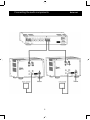
AW400
Monaur
alCl
as
sA Ref
er
enceAmpl
i
fier
Owner
’
sManual
ENG
Owner’s Manual
AW400 Balanced MONO
Power Amplifier
Warning:
To avoid risk of fire or electric shock, do not expose this appliance to rain or moisture.
Verify line voltage before use.
Do not remove cover. No user serviceable parts inside. Refer servicing to qualified service personnel.
The warranty is void if the product is tampered with by non-authorised personnel.
Use only authorised Electrocompaniet service center.
Unpacking the AW400
Immediately upon receipt of the amplifier, inspect the carton for possible damage during shipment. The carton and packaging have been designed to provide the safest possible protection for the transport of your amplifier. Unpack
the unit carefully. Save all packaging materials for future shipment.
The contents of the carton
1 pcs Electrocompaniet AW400 power amplifier
1 pcs AC power cord
1 pcs spare main fuse (located in the fuse drawer of the amplifier)
1 pcs inspection card
Setup procedure
Before connecting the AW 400 to the mains, check that the mains voltage
indicated on the rear panel corresponds to the line voltage in the territory you
intend to use the unit.
How to avoid damages
Do not under any circumstances connect or disconnect equipment when power is turned on. The design of the RCA plug generates a huge transient when
inserted. Connecting or disconnecting equipment with the power on can result in severe damage to both speaker and amplifier.
Never short the speaker outputs to ground or chassis.
How to avoid noise problems
The AW 400 contains delicate circuits that are sensitive to magnetic strayfields.
The unit should not be placed near mains transformers, TV sets etc. Care
should be taken regarding placement of the interconnect cables. Do not run
interconnect cables in parallel with main cords or speaker cables. Keep
interconnect and speaker cables as short as possible.
How to avoid antenna problems
In some set-ups hum may occur when you connect the radio, VCR or TV to your
system. The problem is caused by DC voltage coming from your antenna.
Please contact your cable network operator.
3
How to connect your system
Please read this page carefully and see page 5 and page 6.
Inputs
For optimal performance, the AW400 should be used in balanced mode.
(ie. the preamplifier should have balanced outputs.)
Input configurations
XLR input:
1 = ground
Diagram 3
2 = positive
3 = negative
Outputs
Switch the amplifier off when connecting the speakers.
Output configurations
Diagram 3
Speaker:
Red = positive
White = negative
Please notice:
Both outputs are hot.
Do not under any circumstances short these to ground or chassis.
Input level adjustment
Located on the rear side.
Factory setting of the level adjustment is max volume.
Use it to match levels between amplifiers in bi-amping system.
Link
This output can be used to link more amplifiers together.
The output level on the link output is independent of the input level set on the
amplifier.
Do not short these outputs to ground or together.
How to power up your system
You should always power up your system the following way:
Signal sources (CD player, tuner etc.) first. Then turn on the preamplifier. Allow
30 seconds of preheating before you turn on the power amplifier. After switching
on the power amplifier, there will be a 5 seconds delay before the speakers are
connected. This will prevent large turn on/off transients to reach the speakers.
When turning your system off, you should start by switching off your power
amplifier, then the preamplifier, and finally the signal source devices.
Front panel
Diagram 1
In center of the front panel the Electrocompaniet logo will be lit when power
is on.
4
Connecting the audio components
5
Balanced
6
Warning
The amplifier will be warm.
Due to the high class A operating point used in the Electrocompaniet design,
it is normal that the amplifier feels warm. Proper ventilation will be needed,
and the amplifier should not be covered in. A good rule is to allow 1-2 inches of
air sidewise, and 2-3 inches above the amplifier.
Replacing a blown main fuse
Diagram 2
Always remove the AC cord from the Inlet.
The main fuse is located in a small drawer in the AC inlet of the unit. If, for some
reason the fuse blows, turn the unit off, and remove the AC plug from the inlet.
Open the drawer with a small screwdriver and remove the broken fuse. The
spare fuse is located in the hole in front of the drawer. Push the new fuse gently
out of the hole, and place it in correct position (where the blown fuse was
removed). Push the drawer gently back to the closed position, connect the
power cord and turn the unit on.
NEVER REPLACE A BLOWN FUSE WITH OTHER VALUES THAN PRINTED
ON THE UNIT.
7
Technical Specification AW 400
The following technical data were measured on randomized test objects and are
typical data.
All measurements are made with main voltage 120/240 V 50Hz / 60Hz.
Main voltage 120 / 240 V. Clipping point of the amplifier is set to a level
where total harmonic distortion (THD) is 0.2%.
Output impedance (20-20kHz) ............................
Input impedance mono .......................................
Input sensitivity for rated output ...........................
Max. peak current ................................................
THD (1kHz half power, 8ohm) .............................
THD (1kHz –1dB, 8ohm) ....................................
Noise (input shortened) ......................................
Frequency response ...........................................
<0.01ohm
330kohm
1.6V (adjustable)
>150A
<0.006%
<0.007%
<130uV
DC-65kHz -3dB
Rated output power
10% change in line voltage will give app. 20% change in output power.
8 ohm 400 W
4 ohm 765 W
2 ohm 1010 W
Dimensions
Width
358mm
Depth 470mm
Height 261mm
Weight 25kg
(14,1)
(18,5”)
(10,2”)
(55lbs)
The manufacturer reserves the right to alter these specifications without further notice
8
If Service is needed
Your dealer will have all relevant information regarding the service station in
your area, and will ensure that your unit is serviced with minimum delay. It is
our general policy to have your unit returned to you within five working days.
This is an average time, and can vary locally, depending on the workload at that
particular service station. If, for some reason, there are no service facilities
available in your country, please ship the unit to the following address:
Electrocompaniet as,
Breivikveien 7,
N-4120 Tau,
Norway
Service department: [email protected]
Web: www.electrocompaniet.com
The end user is responsible for all shipping charges, insurance, re-importation
and duty charges. When shipping a product to the factory for service, always
include the following:
1. A sales slip or other proof of purchase if repair is claimed under warranty.
2. A proforma invoice with value of goods, stating that the amplifier is returned to Norway for repair.
3. An accompanying letter describing faults, symptoms, or problems with the unit.
4. Always ship the unit in its original carton and packaging material to
prevent damage in transit.
Electrocompaniet will not cover damages incurred in transit. If you require
further information concerning the operation of the unit, or if you have any
questions related to service, please do not hesitate to contact your dealer or
your national distributor.
9
Madei
nNor
way
W W W .ELECTRO CO M PANIET.NO