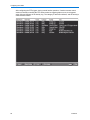
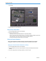
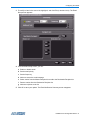
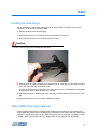
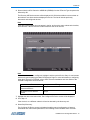
1
Installation and
Configuration Guide
Intellex®
Version 4.2
Part Number 8200-2603-01 A0
Notice
The information in this manual was current when published. The manufacturer reserves the right to revise and improve its products.
All specifications are therefore subject to change without notice.
Copyright
Under copyright laws, the contents of this manual may not be copied, photocopied, reproduced, translated or reduced to any
electronic medium or machine-readable form, in whole or in part, without prior written consent of Tyco International Ltd. © 2008 and
its Respective Companies. All Rights Reserved.
American Dynamics
6600 Congress Avenue
Boca Raton, FL 33487 U.S.A.
Customer Service
Thank you for using American Dynamics products. We support our products through an extensive worldwide network of dealers. The
dealer through whom you originally purchased this product is your point of contact if you need service or support. Our dealers are
empowered to provide the very best in customer service and support. Dealers should contact American Dynamics at (800) 507-6268
or (561) 912-6259 or on the Web at www.americandynamics.net.
Trademarks
Intellex® is a registered trademark of Sensormatic Electronics Corporation. Windows® is a registered trademark of Microsoft
Corporation. PS/2® is a registered trademark of International Business Machines Corporation. Sony® is a registered trademark of
Sony Corporation.
Trademarked names are used throughout this manual. Rather than place a symbol at each occurrence, trademarked names are
designated with initial capitalization. Inclusion or exclusion is not a judgment on the validity or legal status of the term.
ii
Warnings
To reduce risk of electric shock, do not remove cover. No user serviceable parts inside. Refer servicing to qualified service personnel.
Do not expose this appliance to rain or moisture.
Do not install this product in hazardous areas where highly combustible or explosive products are stored or used.
This equipment is a Class 1 laser product incorporating a Class 1 laser diode and it complies with FDA radiation performance standards, 21 CFR subchapter J and the Canadian Radiation Emitting Devices Act, REDRC1370.
The lightning flash/arrowhead symbol, within an equilateral triangle, alerts the user to the presence of a shock hazard
within the product’s enclosure.
Danger of explosion if battery is incorrectly replaced. Replace only with the same or equivalent type recommended by
the battery manufacturer. Dispose of used batteries according to the battery manufacturer’s instructions.
Zur vermeidung eines stromschlages darf das gehäuse nicht entfernt werden. es enthält keine vom benutzer zu
wartenden teile. überlassen sie die wartung nur qualifiziertem fachpersonal.
Es besteht die Gefahr einer Explosion, wenn die Batterie nicht ordnungsgemäß ausgetauscht wird.
FCC COMPLIANCE
This equipment has been tested and found to comply with the limits for a Class “A” digital device, pursuant to part 15 of
the FCC Rules. These limits are designed to provide reasonable protection against harmful interference when the equipment is operated in a commercial environment. This equipment generates, uses and can radiate radio frequency energy
and, if not installed and used in accordance with the instruction manual, may cause interference to radio communications. Operation of this equipment in a residential area is likely to cause harmful interference in which case the user will
be required to correct the interference at their own expense.
This product was FCC verified under test conditions that included the use of shielded I/O cables and connectors between system components. To be in compliance with FCC regulations, the user must use shielded cables and connectors for all except power.
EQUIPMENT MODIFICATION CAUTION
Changes or modifications not expressly approved by Sensormatic, the party responsible for FCC compliance, could void
the user’s authority to operate the equipment and could create a hazardous condition
This class A digital apparatus complies with Canadian ICES-003. Cet appareil numérique de la classe A est conforme
à la norme NMB-003 du Canada.
Rack Mounting
Consult with the supplier of your equipment rack for adequate rack mounting means, with proper consideration for the
weight of this product.
Consult with the manufacturer of your rack regarding the proper hardware and procedure of mounting this product in a
safe and useable fashion
Avoid uneven loading or mechanical instability when rack mounting units.
Make sure that units are installed to get enough air flow for safe operation.
The maximum temperature for rack-mounted units is 35° C.
Avoid uneven loading or mechanical instability when rack mounting units.
Check product label for power supply requirements to assure that no overloading of supply circuits or overcurrent protection occurs.
Mains grounding must be reliable and uncompromised by any connections.
iii
License Information
READ THIS LICENSE AGREEMENT BEFORE OPENING THE DISK PACKAGE, INSTALLING THE SOFTWARE, OR USING YOUR
SYSTEM.
THIS LICENSE AGREEMENT DEFINES YOUR RIGHTS AND OBLIGATIONS. BY BREAKING THE SEAL ON THIS PACKAGE,
INSTALLING THE SOFTWARE, OR USING YOUR SYSTEM, YOU AGREE TO ALL OF THE TERMS AND CONDITIONS OF THIS
AGREEMENT. IF YOU DO NOT AGREE TO ALL OF THE TERMS AND CONDITIONS OF THIS AGREEMENT, YOU MAY, WITHIN
30 DAYS, RETURN THIS PACKAGE, ALL THE DOCUMENTATION, AND ALL ACCOMPANYING MATERIAL(S) TO THE POINT OF
PURCHASE FOR A REFUND.
SOFTWARE LICENSE
The Software includes the computer code, programs, and files, the associated media, hardware or software keys, any printed
material, and any electronic documentation. The Software may be provided to you pre-installed on a storage device (the media) as
part of a system. The Software is licensed, not sold.
GRANT OF LICENSE
This agreement between Sensormatic Electronics Corporation (Sensormatic) and you permits you to use the Software you
purchased. Once you have purchased the number of copies you require, you may use the Software and accompanying material
provided you install and use no more than the licensed number of copies at one time. The Software is only licensed for use with
specified Sensormatic supplied equipment. If the Software is protected by a software or hardware key or other device, the Software
may be used on any computer where the key is installed. If the key locks the Software to a particular System, the Software may only
be used on that System.
OTHER RIGHTS AND LIMITATIONS
•
•
A demonstration copy of the Software is considered purchased and is covered by this license agreement.
You may not de-compile, disassemble, reverse engineer, copy, transfer, modify, or otherwise use the Software except as stated in
this agreement.
• The hardware/software key, where applicable, is your proof of license to exercise the rights granted herein and must be retained
by you. Lost or stolen keys will not be replaced.
• If the Software is provided as part of a System, the Software may only be used with the System.
• You may not sub-license, rent or lease the Software, but you may permanently transfer the Software to another party by
delivering the original disk and material comprising the Software package as well as this license agreement to the other party.
Initial use of the Software and accompanying material by the new user transfers the license to the new user and constitutes the
new user's acceptance of its terms and conditions.
• The Software is not fault tolerant and may contain errors. You agree that the Software will not be used in an environment or
application in which a malfunction of the Software would result in foreseeable risk of injury or death to the operator of the
Software, or to others.
• Sensormatic reserves the right to revoke this agreement if you fail to comply with the terms and conditions of this agreement. In
such an event, you must destroy all copies of the Software, and all of its component parts (e.g., documentation, hardware box,
software key).
• The Software may contain software from third parties that is licensed under a separate End User License Agreement (EULA).
Read and retain any license documentation that may be included with the Software. Compliance with the terms of any third party
EULA is required as a condition of this agreement.
• The Software may require registration with Sensormatic prior to use. If you do not register the Software this agreement is
automatically terminated and you may not use the Software.
• The Microsoft® Windows® Preinstallation Environment Version 1.2, Services Edition software, if included with this software or
system, may be used for boot, diagnostic or recovery purposes only. NOTE: THIS SOFTWARE CONTAINS A SECURITY
FEATURE THAT, IF USED AS AN OPERATING SYSTEM, WILL CAUSE YOUR DEVICE TO REBOOT WITHOUT PRIOR
NOTIFICATION AFTER 24 HOURS OF CONTINUOUS USE OF THE SOFTWARE.
• UPGRADES AND UPDATES. Software Upgrades and Updates may only be used to replace all or part of the original Software.
Software Upgrades and Updates do not increase the number copies licensed to you. If the Software is an upgrade of a
component of a package of Software programs that you licensed as a single product, the Software may be used and transferred
only as part of that single product package and may not be separated for use on more than one computer. Software Upgrades
and Updates downloaded free of charge via a Sensormatic authorized World Wide Web or FTP site may be used to upgrade
multiple systems provided that you are licensed to use the original Software on those systems.
• INTELLEX PLAYER. The Intellex Player Software that is exported with video clips and/or distributed via Sensormatic authorized
World Wide Web site may be copied by you for use within your organization or for distribution to external parties for law
enforcement, investigative, or adjudicative purposes and only to display video recorded by an Intellex system. The Intellex Player
Software may not be sold. All other terms and conditions of this agreement continue to apply.
• TOOLS AND UTILITIES. Software distributed via Sensormatic authorized World Wide Web or FTP site as a tool or utility may be
copied and installed without limitation provided that the Software is not distributed or sold and the Software is only used for the
intended purpose of the tool or utility and in conjunction with Sensormatic products. All other terms and conditions of this
agreement continue to apply.
Failure to comply with any of these restrictions will result in automatic termination of this license and will make available to
Sensormatic other legal remedies.
COPYRIGHT
The Software is a proprietary product of Tyco International Ltd. © 2008 and its Respective Companies. All Rights Reserved.
LIMITED WARRANTY
Sensormatic warrants that the recording medium on which the Software is recorded, hardware key, and the documentation provided
with it, will be free of defects in materials and workmanship under normal use for a period of ninety (90) days from the date of delivery
to the first user. Sensormatic further warrants that for the same period, the software provided on the recording medium under this
iv
license will substantially perform as described in the user documentation provided with the product when used with the specified
hardware.
CUSTOMER REMEDIES
Sensormatic's entire liability and your exclusive remedy under this warranty will be, at Sensormatic's option, to a). attempt to correct
software errors with efforts we believe suitable to the problem, b). replace at no cost the recording medium, software or
documentation with functional equivalents as applicable, or c). refund the license fee and terminate this agreement. Any replacement
item will be warranted for the remainder of the original warranty period. No remedy is provided for failure of the Software if such
failure is the result of accident, abuse, alteration or misapplication. Warranty service or assistance is provided at the original point of
purchase.
NO OTHER WARRANTIES
The above warranty is in lieu of all other warranties, express or implied, including, but not limited to the implied warranties of
merchantability and fitness for a particular purpose. No oral or written information or advice given by Sensormatic, its representatives,
distributors or dealers shall create any other warranty, and you may not rely on such information or advice.
NO LIABILITY FOR CONSEQUENTIAL DAMAGES
In no event will Sensormatic be liable to you for damages, including any loss of profits, loss of data or other incidental or
consequential damages arising out of your use of, or inability to use, the Software or its documentation. This limitation will apply even
if Sensormatic or an authorized representative has been advised of the possibility of such damages. Further, Sensormatic does not
warrant that the operation of the Software will be uninterrupted or error free. This limited warranty gives you specific legal rights. You
may have other rights that vary from state to state. Some states do not allow the exclusion of incidental or consequential damages, or
the limitation on how long an implied warranty lasts, so some of the above limitations may not apply to you.
GENERAL
If any provision of the agreement is found to be unlawful, void, or for any reason unenforceable, then that provision shall be severed
from this agreement and shall not affect the validity and enforceability of the remaining provisions. This agreement is governed by the
laws of the State of Florida. You should retain proof of the license fee paid, including model number, serial number and date of
payment, and present such proof of payment when service or assistance covered by this warranty is requested.
U.S. GOVERNMENT RESTRICTED RIGHTS
The software and documentation are provided with RESTRICTED RIGHTS. Use, duplication, or disclosure by the Government is
subject to restrictions as set forth in subparagraph (c)(1)(ii) of the Rights in Technical Data and Computer Software clause at DFARS
252.227-7013 or subparagraph (c)(1) and (2) of the Commercial Computer Software-Restricted Rights at 48 CFR 52.227-19, as
applicable. Manufacturer is Sensormatic Electronics Corporation, 6600 Congress Avenue, Boca Raton, FL, 33487.
v
vi
Contents
Before Installing the Intellex
Safety Guidelines . . . . . . . . . . . . . . . . . . . . . . . . . . . . . . . . . . . . . . . . . . . . . . . . . . . . . 1
System Requirements . . . . . . . . . . . . . . . . . . . . . . . . . . . . . . . . . . . . . . . . . . . . . . . . . 2
Programmable Settings. . . . . . . . . . . . . . . . . . . . . . . . . . . . . . . . . . . . . . . . . . . . . . 4
Video Format. . . . . . . . . . . . . . . . . . . . . . . . . . . . . . . . . . . . . . . . . . . . . . . . . . . . . . 4
Video Level . . . . . . . . . . . . . . . . . . . . . . . . . . . . . . . . . . . . . . . . . . . . . . . . . . . . . . . 4
Alarm . . . . . . . . . . . . . . . . . . . . . . . . . . . . . . . . . . . . . . . . . . . . . . . . . . . . . . . . . . . . 4
Display. . . . . . . . . . . . . . . . . . . . . . . . . . . . . . . . . . . . . . . . . . . . . . . . . . . . . . . . . . . 5
Record Options . . . . . . . . . . . . . . . . . . . . . . . . . . . . . . . . . . . . . . . . . . . . . . . . . . . . 5
Rear Panel Connectors . . . . . . . . . . . . . . . . . . . . . . . . . . . . . . . . . . . . . . . . . . . . . . 5
Power Supply . . . . . . . . . . . . . . . . . . . . . . . . . . . . . . . . . . . . . . . . . . . . . . . . . . . . . 6
Environmental Requirements . . . . . . . . . . . . . . . . . . . . . . . . . . . . . . . . . . . . . . . . . 6
Front Panel . . . . . . . . . . . . . . . . . . . . . . . . . . . . . . . . . . . . . . . . . . . . . . . . . . . . . . . 7
Rack-mounted Intellex . . . . . . . . . . . . . . . . . . . . . . . . . . . . . . . . . . . . . . . . . . . . . 8
Installing Hardware
Connecting Cameras and Peripherals . . . . . . . . . . . . . . . . . . . . . . . . . . . . . . . . . . . . . 9
Video Devices . . . . . . . . . . . . . . . . . . . . . . . . . . . . . . . . . . . . . . . . . . . . . . . . . . . . . 9
Connecting Audio Devices (optional) . . . . . . . . . . . . . . . . . . . . . . . . . . . . . . . . . . 10
Connecting Optional Components . . . . . . . . . . . . . . . . . . . . . . . . . . . . . . . . . . . . 11
Connecting Alarms to the Intellex . . . . . . . . . . . . . . . . . . . . . . . . . . . . . . . . . . . . . 13
Connecting the Intellex to a Network. . . . . . . . . . . . . . . . . . . . . . . . . . . . . . . . . . . 15
Rack Mounting the System . . . . . . . . . . . . . . . . . . . . . . . . . . . . . . . . . . . . . . . . . . . . 16
Ensuring Proper Rack Mounting . . . . . . . . . . . . . . . . . . . . . . . . . . . . . . . . . . . . . . 16
Safety Guidelines . . . . . . . . . . . . . . . . . . . . . . . . . . . . . . . . . . . . . . . . . . . . . . . . . 16
Miscellaneous Parts . . . . . . . . . . . . . . . . . . . . . . . . . . . . . . . . . . . . . . . . . . . . . . . . . . 16
Configuring the Intellex
Configuring the Operating System . . . . . . . . . . . . . . . . . . . . . . . . . . . . . . . . . . . . . . . 17
Microsoft Installer . . . . . . . . . . . . . . . . . . . . . . . . . . . . . . . . . . . . . . . . . . . . . . . . . 17
Exiting to Windows . . . . . . . . . . . . . . . . . . . . . . . . . . . . . . . . . . . . . . . . . . . . . . . . 17
Configuring the Intellex Ultra composite video output feature. . . . . . . . . . . . . . . . 17
Setting the Intellex Ultra VACD3 output mode and graphics overlay. . . . . . . . . 17
Setting System Information . . . . . . . . . . . . . . . . . . . . . . . . . . . . . . . . . . . . . . . . . . 19
Setup Options . . . . . . . . . . . . . . . . . . . . . . . . . . . . . . . . . . . . . . . . . . . . . . . . . . . . . . 21
Setting Up Cameras . . . . . . . . . . . . . . . . . . . . . . . . . . . . . . . . . . . . . . . . . . . . . . . 21
Termination . . . . . . . . . . . . . . . . . . . . . . . . . . . . . . . . . . . . . . . . . . . . . . . . . . . . 22
Gain Mode . . . . . . . . . . . . . . . . . . . . . . . . . . . . . . . . . . . . . . . . . . . . . . . . . . . . . 22
vii
Contents
Camera Control . . . . . . . . . . . . . . . . . . . . . . . . . . . . . . . . . . . . . . . . . . . . . . . . . 23
User-Defined Handlers . . . . . . . . . . . . . . . . . . . . . . . . . . . . . . . . . . . . . . . . . . . 24
PTZ Cameras. . . . . . . . . . . . . . . . . . . . . . . . . . . . . . . . . . . . . . . . . . . . . . . . . . . 26
Covert Mode . . . . . . . . . . . . . . . . . . . . . . . . . . . . . . . . . . . . . . . . . . . . . . . . . . . . . 29
Setting Up Schedules . . . . . . . . . . . . . . . . . . . . . . . . . . . . . . . . . . . . . . . . . . . . . . 30
Regular Schedules. . . . . . . . . . . . . . . . . . . . . . . . . . . . . . . . . . . . . . . . . . . . . . . 30
Setting Up Live Filters . . . . . . . . . . . . . . . . . . . . . . . . . . . . . . . . . . . . . . . . . . . . 31
Setting Up Light Change . . . . . . . . . . . . . . . . . . . . . . . . . . . . . . . . . . . . . . . . . . 33
Select a Data Lifetime Mode . . . . . . . . . . . . . . . . . . . . . . . . . . . . . . . . . . . . . . . 34
Setting Up Custom Schedules . . . . . . . . . . . . . . . . . . . . . . . . . . . . . . . . . . . . . . 34
Setting Up Camera Rate . . . . . . . . . . . . . . . . . . . . . . . . . . . . . . . . . . . . . . . . . . . . 36
Adding, Editing, and Deleting Text Source . . . . . . . . . . . . . . . . . . . . . . . . . . . . . . 39
Setting Up Audio . . . . . . . . . . . . . . . . . . . . . . . . . . . . . . . . . . . . . . . . . . . . . . . . . . 41
Setting Up Classic Security Options . . . . . . . . . . . . . . . . . . . . . . . . . . . . . . . . . . . 42
Setting Up Record Mode . . . . . . . . . . . . . . . . . . . . . . . . . . . . . . . . . . . . . . . . . . . . 44
Setting Up Alarms . . . . . . . . . . . . . . . . . . . . . . . . . . . . . . . . . . . . . . . . . . . . . . . . . 44
Setting Up Display Settings. . . . . . . . . . . . . . . . . . . . . . . . . . . . . . . . . . . . . . . . . . 47
Setting the Date and Time. . . . . . . . . . . . . . . . . . . . . . . . . . . . . . . . . . . . . . . . . . . 47
Setting Up the Port Address, Live Network Client Connections and
Streaming Clients . . . . . . . . . . . . . . . . . . . . . . . . . . . . . . . . . . . . . . . . . . . . . . . . . 48
Setting Up Storage Options. . . . . . . . . . . . . . . . . . . . . . . . . . . . . . . . . . . . . . . . . . 48
Setting Up the Archive Schedule. . . . . . . . . . . . . . . . . . . . . . . . . . . . . . . . . . . . . . 49
Setting Up Email Notification. . . . . . . . . . . . . . . . . . . . . . . . . . . . . . . . . . . . . . . . . 50
Sending a Test Message . . . . . . . . . . . . . . . . . . . . . . . . . . . . . . . . . . . . . . . . . . 52
Saving the Set Up . . . . . . . . . . . . . . . . . . . . . . . . . . . . . . . . . . . . . . . . . . . . . . . . . 53
Configuring Anti-Virus Detection
Configuring the McAfee Module. . . . . . . . . . . . . . . . . . . . . . . . . . . . . . . . . . . . . . . . . 55
Configuring the Symantec Module . . . . . . . . . . . . . . . . . . . . . . . . . . . . . . . . . . . . . . . 56
Custom Scan. . . . . . . . . . . . . . . . . . . . . . . . . . . . . . . . . . . . . . . . . . . . . . . . . . . . . 57
RAID
Installing the Hard Drives . . . . . . . . . . . . . . . . . . . . . . . . . . . . . . . . . . . . . . . . . . . . . . 59
3Ware 3DM2 Utility User’s Manual . . . . . . . . . . . . . . . . . . . . . . . . . . . . . . . . . . . . . . 59
Setting Up Email Alerts . . . . . . . . . . . . . . . . . . . . . . . . . . . . . . . . . . . . . . . . . . . . . . . 60
Adding a User to the Email Recipient List . . . . . . . . . . . . . . . . . . . . . . . . . . . . . . 60
Removing a User from the Email Recipient List . . . . . . . . . . . . . . . . . . . . . . . . . . 60
Changing Events for Email Notification . . . . . . . . . . . . . . . . . . . . . . . . . . . . . . . . 60
Troubleshooting a RAID Problem . . . . . . . . . . . . . . . . . . . . . . . . . . . . . . . . . . . . . . . 61
Offline Array . . . . . . . . . . . . . . . . . . . . . . . . . . . . . . . . . . . . . . . . . . . . . . . . . . . . . 61
Degraded Array . . . . . . . . . . . . . . . . . . . . . . . . . . . . . . . . . . . . . . . . . . . . . . . . . . . 61
Array Degraded Status . . . . . . . . . . . . . . . . . . . . . . . . . . . . . . . . . . . . . . . . . . . . . 62
Recovering RMS Offline Array to Functional System . . . . . . . . . . . . . . . . . . . . . . 62
viii
Intellex®
Contents
Checking the Array Status . . . . . . . . . . . . . . . . . . . . . . . . . . . . . . . . . . . . . . . . . 62
Offline Array . . . . . . . . . . . . . . . . . . . . . . . . . . . . . . . . . . . . . . . . . . . . . . . . . . . . 62
Setting Up a Logical Drive . . . . . . . . . . . . . . . . . . . . . . . . . . . . . . . . . . . . . . . . . . . . . 63
Setting Up a Drive at the Intellex Level . . . . . . . . . . . . . . . . . . . . . . . . . . . . . . . . . 63
Questions & Answers. . . . . . . . . . . . . . . . . . . . . . . . . . . . . . . . . . . . . . . . . . . . . . . . . 64
Intellex IP
Intellex IP . . . . . . . . . . . . . . . . . . . . . . . . . . . . . . . . . . . . . . . . . . . . . . . . . . . . . . . . . . 65
Setting Up the Intellex IP System . . . . . . . . . . . . . . . . . . . . . . . . . . . . . . . . . . . . . 65
Setting Up Parameters for IP Devices. . . . . . . . . . . . . . . . . . . . . . . . . . . . . . . . . . 68
Setting up a PAL Bosch IP camera . . . . . . . . . . . . . . . . . . . . . . . . . . . . . . . . . . . . 69
Adding a VideoEdge™ Device . . . . . . . . . . . . . . . . . . . . . . . . . . . . . . . . . . . . . . . 72
Changing an AD device configuration . . . . . . . . . . . . . . . . . . . . . . . . . . . . . . . . . . 75
Modifying an IP Encoder’s or IPSDU8’s configuration. . . . . . . . . . . . . . . . . . . . 75
Modifying an IP Encoder’s or IPSDU8’s Device Setup . . . . . . . . . . . . . . . . . . . 75
Setting the Record Rate . . . . . . . . . . . . . . . . . . . . . . . . . . . . . . . . . . . . . . . . . . . . 76
Setting Up the Rate . . . . . . . . . . . . . . . . . . . . . . . . . . . . . . . . . . . . . . . . . . . . . . 77
Connecting to Multiple Networks. . . . . . . . . . . . . . . . . . . . . . . . . . . . . . . . . . . . . . 77
Intellex Web Server
Overview . . . . . . . . . . . . . . . . . . . . . . . . . . . . . . . . . . . . . . . . . . . . . . . . . . . . . . . . . . 79
Minimum System Requirements . . . . . . . . . . . . . . . . . . . . . . . . . . . . . . . . . . . . . . . . 79
Viewing the IP Address and Machine Name . . . . . . . . . . . . . . . . . . . . . . . . . . . . . . . 79
IP Address . . . . . . . . . . . . . . . . . . . . . . . . . . . . . . . . . . . . . . . . . . . . . . . . . . . . . 79
Machine name . . . . . . . . . . . . . . . . . . . . . . . . . . . . . . . . . . . . . . . . . . . . . . . . . . 79
User Accounts . . . . . . . . . . . . . . . . . . . . . . . . . . . . . . . . . . . . . . . . . . . . . . . . . . . . . . 80
Creating an Account . . . . . . . . . . . . . . . . . . . . . . . . . . . . . . . . . . . . . . . . . . . . . . . 80
Deleting an Account . . . . . . . . . . . . . . . . . . . . . . . . . . . . . . . . . . . . . . . . . . . . . . . 80
Connecting to an Intellex . . . . . . . . . . . . . . . . . . . . . . . . . . . . . . . . . . . . . . . . . . . . . . 81
RAID Storage System Compatibility
Drive Failure Notification . . . . . . . . . . . . . . . . . . . . . . . . . . . . . . . . . . . . . . . . . . . . . . 83
Configuring Remote System Logging . . . . . . . . . . . . . . . . . . . . . . . . . . . . . . . . . . 83
Sample Drive Failure Notification . . . . . . . . . . . . . . . . . . . . . . . . . . . . . . . . . . . . . 84
Large Database Support . . . . . . . . . . . . . . . . . . . . . . . . . . . . . . . . . . . . . . . . . . . . . . 85
Configuring Large Database Support . . . . . . . . . . . . . . . . . . . . . . . . . . . . . . . . . . 85
Index
87
Installation and Configuration Guide
ix
Contents
x
Intellex®
Before Installing the Intellex
Safety Guidelines
• Ensure that installation work complies with electrical, fire, safety, communication, and building
codes and ordinances.
• Install the Intellex in a clean, dry location, where temperature and humidity are within product
specifications.
• Install the Intellex away from Electrical Magnetic Inducing (EMI) equipment, such as electrical
generators, motors, unshielded speakers, and high voltage cables.
• Allow adequate all-around clearance and accessibility for cables, peripherals, ventilation,
maintenance, and operation.
• Ensure that equipment is mounted level and securely.
• Ensure that equipment has a stable AC power source.
• Use of an Uninterruptible Power Supply (UPS) unit is highly recommended. UPS units protect
critical computing systems from power fluctuations and losses that may cause loss of data or
damage to the system.
• Install surge protectors on all power cables to protect against severe power fluctuations.
• Check the product label for power supply requirements to assure that no overloading of power
supply circuits or overcurrent protection occurs.
• Ensure that fans undergo periodic, scheduled maintenance and remain free and clear of dust.
• Electrical grounding must be reliable and uncompromised by any connections.
Note
The power supply automatically detects 115 or 230 volts input and has no power switch.
• Locate product documentation and software, and keep in a safe and accessible location.
• For all rack-mounted electrical equipment, ensure adequate air flow around the unit for safe
operation. The maximum temperature for rack-mounted units is 35° C or 95° F.
Note
Refer to the Intellex Ultra Quick Setup Guide for a visual overview of system contents, how to set
up and connect the components, and how to power up the unit.
1
Before Installing the Intellex
System Requirements
Note
This section includes system requirements for Intellex Ultra, DVMS, and LT.
Intellex 4.2
Hardware
Configuration
Ultra
8- and 16-Camera
Rackmount
LT
Hard drive options
500, 1000, 1500,
2000 GB
250 or 500GB
250, 500, or 750
GB
160 GB or 320
GB
Memory
Media drive
512 MB
512 MB
512 MB
512 MB
Includes DVD-RW
DVD-RW or CD-RW
DVD-RW
CD-RW
3U
4U
4U
4U
Chassis
Operating System: Intellex 4.2 software is compatible only with Microsoft XP Pro SP2.
Note
* = a feature is enabled
Features
Ultra
DVMS
16Camera
LT-
8Camera
4Camera
8Camera
16Camera
Number of cameras
16
16
8
4
8
16
Aggregate Record
rate
480
120
60
60
60
60
Client connections
20
20
20
20
20
20
Resolution
True 4CIF PAL:
704 × 576 4CIF
704 × 288 2CIF
352 × 288 1CIF
640 × 240
320 × 240
640 × 240
320 × 240
640 × 240
320 × 240
640 × 240
320 × 240
640 × 240
320 × 240
*
*
*
True 4 CIF NTSC:
704 × 480 4CIF
704 × 240 2CIF
352 × 240 1CIF
Classic 4CIF:
640 × 480 4CIF
640 × 240 2CIF
320 × 240 1CIF
2
Multi-camera
playback
*
*
*
Camera selectable
frame rates
*
*
*
Video analysis tools
*
Premier
only
User-defined
camera handler
*
*
*
Advanced text
*
Premier
only
Premier
only
Alarm-triggered
dome actions
*
*
*
*
*
*
Custom weekend
*
*
*
*
*
*
Intellex®
Before Installing the Intellex
Features
Ultra
DVMS
LT-
16Camera
8Camera
4Camera
8Camera
16Camera
*
*
*
*
*
*
Hard drive failure
advance notification
*
*
*
Network archive
*
*
*
Activity log
*
*
*
Direct dome control
(USB-SNET)
*
*
*
Email alarm/system
events
*
*
*
*
*
*
Audio recording
*
Premier
only
Premier
only
Premier
only
Premier
only
Premier
only
Text recording
*
Premier
only
Premier
only
Premier
only
Premier
only
Premier
only
Tape archive
*
*
*
Installation and Configuration Guide
3
Before Installing the Intellex
Programmable Settings
Setting
Default Value
Camera names
Camera1–Camera16
Camera termination
75 Ω
Security access
Disabled
Administrator PIN
1234
Schedule mode
Regular
Record settings
Circular Mode, normal sensitivity, 60 ips (50 ips PAL)
Alarm duration
5 seconds
Alarm record settings
30 ips (25 ips PAL), normal quality, normal sensitivity
Alarm on video loss
Enabled
Alarm display message
Enabled
Latch message
Disabled
Alarm input names
AlarmIn1–AlarmIn16
Alarm input polarity
Active Low
Live sequencer dwell
2 seconds
Live display format
1×1
Playback overlay
Enabled, Upper-Right
Video Format
Color (input and output)
NTSC or PAL
B&W (input and output)
EIA or CCIR
Video Level
Camera inputs
1.0 V p-p, 75 Ω
Camera outputs
1.0 V p-p, 75 Ω
Analog output
1.0 V p-p, 75 Ω
Alarm
4
Alarm inputs
4, 8, or 16 inputs. Activated by contact closure or TTL/CMOS signal.
Programmable polarity.
Alarm outputs
4, 8, or 16 outputs. TTL/CMOS compatible active high. Driven to +4V and
can drive 6mA. Initialized to inactive low on power-up.
Alarm duration
Programmable from 5 seconds – 5 minutes.
Intellex®
Before Installing the Intellex
Display
Color palette
16,777,216 colors (32 bits)
Gray shades
256 (8 bits)
Display controls
Mouse-selectable buttons with indicator lights
Note
Pixel count reflects the digital display area and is not affected by NTSC/PAL signal differences.
Format
Menu Mode (pixels)
1×1
2×2
3×3
4×4
(16 channel only)
Full Screen Mode (pixels)
768x576 (Ultra Only)
1024x768 (Ultra Only)
640×480
800×600
384x288 (Ultra Only)
512x384 (Ultra Only)
320×240
400×300
256x192 (Ultra Only)
341x256 (Ultra Only)
213×160
267×200
192x144 (Ultra Only)
256x192 (Ultra Only)
160×120
200×150
Record Options
Record mode
Linear, Circular
Image sensitivity
High, Normal
Image quality
Super, Normal, Extended Record
Ultra
Record rate
DVMS
LT:
NTSC:
480, 240, 120, 60, 30, 15, 7.5, 2.5,
and 1 ips (images per second)
PAL:
400, 200, 100, 50, 25, 12.5, 6.25, 2,
and 0.8 ips
NTSC:
120, 60, 30, 15, 7.5, 2.5, and 1 ips
PAL:
100, 50, 25, 12.5, 6.25, 2, and 0.8
ips
NTSC:
60, 30, 15, 7.5, and 2.5 ips
PAL:
50, 25, 12.5, 6.25, and 2 ips
Rear Panel Connectors
Note
* = with optional looping board
** = 16-camera only
Connector
Use
Applies to
Intellex:
Camera In
BNC. Composite video input from camera.
Ultra, DVMS, LT
Camera Out
BNC. Composite video output from camera (passive loop
through). Termination is set within Intellex.
Ultra*, DVMS**, LT**
Installation and Configuration Guide
5
Before Installing the Intellex
Connector
Use
Applies to
Intellex:
Alarm
Connector block with screw terminals.
Ultra, DVMS, LT
Keyboard
Standard PS/2-style connector.
All (not supplied)
Mouse
Input device with standard PS/2-style connector.
All
USB
These connectors are used to add RS-232 ports, data
storage devices, USB-Sensornet dome control modules,
and other accessories to the Intellex.
All
Monitor
HD15-S. SVGA monitor output for live display.
All
Call Monitor
(Composite)
BNC composite output to optional call monitor display.
TV Out
(Composite)
Composite video output.
TV Out (S-Video)
S-Video. Composite video output.
Serial
DB9-P. Dome controller (Sensormatic VM16 or American
Dynamics ADTT16) input.
SCSI-3
High density 68-pin female connector. For use with
external storage devices.
Network
RJ-45. Category 3 or Category 5 twisted-pair Ethernet
(CAT 3 TPE or CAT 5 TPE) connector.
All
Microphone
Compatible with dynamic, condenser, and electret
microphones. Line input is compatible with 1 Vrms line
level audio sources.
All (optional on IP)
Ultra, DVMS**, LT**
DVMS, LT, Ultra
DVMS**
All
Optional
Power Supply
Input
100 - 240 VAC, 50-60 Hz, less than 5A
Requires IEC-320-C13 plug
Environmental Requirements
Temperature
41–95° F (5–35° C)
Humidity
5–95% RH noncondensing
Storage temperature
14° –140° F (10–60° C)
Caution
Intellex Operating Temperature Range
The specified operating temperature range for the Intellex Ultra is 5° C to 35° C (41° F to 95° F). The product
meets all functional specifications in this temperature range, and all of the internal components are within their
manufacturers’ specified temperature limits. Extended operation at elevated temperatures reduces the life of
electronic components and reduces overall system reliability. It is recommended that the ambient temperature be
maintained at 15° C to 24° C (59° F to 75° F) to maximize the life of the electronic components. The ambient
temperature is the air temperature in the immediate vicinity of the chassis. For example, if the chassis is mounted in
a rack or lock box, the ambient temperature is the air temperature within the rack or lock box.
6
Intellex®
Before Installing the Intellex
Front Panel
DVD-RW Drive
Power indicator
Power switch
Reset switch
REC (recording indicator)
illuminates when the unit
records images to the
image database.
Ultra
POWER
Hard drives
REC
ALARM
4_0FP_1
Alarms indicator
• Illuminates when alarm events
occur but have not been reviewed.
• Blinks when the notification screen
appears.
Power: Insert the reset tool into
the pinhole to power on or off.
Reset: If the unit does not power
on, insert the reset tool into the
pinhole to reset. The unit powers
on and performs standard
diagnostics.
USB Connectors
Power indicator
CD-RW/DVD Drive
DVMS/LT
3_2FP_1
REC (recording indicator)
illuminates when the unit records
images to the image database.
Alarms indicator
• Illuminates when alarm events
occur but have not been reviewed.
• Blinks when the notification screen
appears.
Installation and Configuration Guide
7
Before Installing the Intellex
Rack-mounted Intellex
Power switch
Alarms indicator
Reset button
Power indicator
CD Drive
3_2FP_1
Hard drive activity
Fan
Do not modify any BIOS or system settings or reconfigure any hard drives. During power-up, the
Intellex splash screen appears. During initial power-up, a message may appear. Do not press
buttons on the front panel or keys on the keyboard until this screen and message disappears,
which may take 2 minutes. Otherwise, you may interrupt the start-up process and affect the unit’s
operation. Double-clicking the Intellex icon during the start-up process can lock the Intellex or
cause it to go into an unrecoverable condition.
8
Intellex®
Installing Hardware
Connecting Cameras and Peripherals
Caution
Protect the unit against lightning. If part of a cable is installed outside a building, the entire cable is
vulnerable to lightning. Install surge protectors on all vulnerable cables.
Video Devices
1 Connect the cameras:
a
Connect the video cables from the cameras to the left BNC connector of each pair of
connectors on the rear of the unit.
b Terminate the video using the switches at each BNC connector (8-camera system) or the
Intellex Setup screen. If you use the switches to select the 75 Ω termination, select Hi-Z
from the Intellex Setup screen. See page 20.
Note
To use the Intellex Setup screen to select the 75 Ω termination, set the switches at each BNC to
infinity.
2 Connect any External Storage Modules (ESMs) through the Firewire connectors.
3 Connect the VGA cable from an SVGA monitor to the VGA monitor connector.
9
Installing Hardware
4 Connect an optional call monitor to the BNC connector on the Call Monitor board to see live
video from a single camera (call mode) or from alarmed cameras in sequence (spot mode).
BNC Camera in
Ultra
VGA monitor
INT40_BP
Power entry
GLan 1
Mouse
BNC Camera in
Passive loop through/
camera out
GLan 2 VACD 3
Sound card
Call Monitor BNC
DVMS/Rackmount
Power entry
Mouse
VGA monitor
Firewire
Ethernet 10/100
Note
The layout of the rear panel varies slightly with different motherboards.
Connecting Audio Devices (optional)
1 Connect the microphone or audio source to the Intellex unit through the color-coded 3.5 mm
audio connectors on the back of the unit.
For the best quality sound, use a pre-amplifier with appropriate filtering with a compatible
microphone.
10
Intellex®
Installing Hardware
2 Connect a line level signal input and speakers.
Ultra
Speaker
output (green)
INT40_BP
Microphone
connector (pink)
Line In
(blue)
DVMS/Rackmount
Microphone
connector (pink)
Speaker output
(green)
Line In (blue)
Note
The layout of the rear panel varies slightly with different motherboards.
Connecting Optional Components
You can connect the Touch Tracker, keyboard, mouse, printer, and other devices.
Adding a keyboard to the Intellex unit provides access to the operating system’s features such as
Log Off and Shut Down and to other applications. The Intellex Security Option does not control this
access. To restrict user access to these features, do not install a keyboard.
• Connect a dome controller (Sensormatic VM16E or American Dynamics ADTT16E) to the
COM2 connector through an electrical interface module (EIM).
• Connect a printer.
• Connect a matrix switcher for dome control or devices for serial text input through the USB port.
• Attach the mouse and keyboard.
Installation and Configuration Guide 11
Installing Hardware
• For DVMS only, connect an optional Live/Playback monitor to the BNC connector on the VACD
board to view live, or playback, video without the Intellex interface.
Ultra
INT40_BP
Keyboard
USB ports
COM2
connector
Printer
DVMS/Rackmount
Mouse
Printer
Keyboard
USB ports
Live/Playback
BNC connector
Note
The layout of the rear panel varies slightly with different motherboards.
12
Intellex®
Installing Hardware
Connecting Alarms to the Intellex
The alarm connectors on the back of the unit accept up to 18 alarm inputs and 16 alarm outputs.
The alarm outputs are TTL outputs 4VDC, 6 mA.
Ultra
INT40_BP
Alarm connectors
DVMS
Earth point for 16
Channel
Note
The layout of the rear panel varies slightly with different motherboards.
Note
For EMC compliance shielded twisted pair alarm cable should be used on the DVMS with the
shield terminated at the earth point.
The polarity of all alarm inputs is programmable. However, the polarity of all alarm outputs is
active–high. Alarm outputs are initialized to inactive–low on power-up.
Attach the alarm inputs, outputs, and grounds to the connectors, according to the pin assignment.
Use the Time Sync Signal (Alarm In 17) to reset the system time of the Intellex to the nearest hour.
Time
Time resets to
<30 minutes before the hour
Forward to the next hour (0 min, 0 sec)
<30 minutes after the hour
Back to the previous hour (0 min, 0 sec)
Use the Export Signal input (Alarm In 18) to start a Fill CD operation without access to the normal
user interface. Use a contact closure, such as an external switch, to execute the Fill CD command
to export the last 500 MB of data to a CD
Installation and Configuration Guide 13
Installing Hardware
16-Channel
Alarms In
Pin No.
14
Assignment
Alarms Out
Pin No.
Assignment
1
Input 1
1
Output 1
2
Input 2
2
Output 2
3
Input 3
3
Output 3
G
Ground
G
Ground
4
Input 4
4
Output 4
5
Input 5
5
Output 5
6
Input 6
6
Output 6
G
Ground
G
Ground
7
Input 7
7
Output 7
8
Input 8
8
Output 8
9
Input 9
9
Output 9
G
Ground
G
Ground
10
Input 10
10
Output 10
11
Input 11
11
Output 11
12
Input 12
12
Output 12
G
Ground
G
Ground
13
Input 13
13
Output 13
14
Input 14
14
Output 14
15
Input 15
15
Output 15
G
Ground
G
Ground
16
Input 16
16
Output 16
17
Time Sync
COM
Reserved
18
Export signal
NC
Reserved
G
Ground
NO
Reserved
Intellex®
Installing Hardware
8-Channel
On an 8-channel Intellex, the alarm adapter is a rectangular board that connects into the DB37
port. The pinout looks like this:
Alarms In
Pin No.
Assignment
Alarms Out
Pin No.
Assignment
1
Input 1
1
Output 1
G
Ground
G
Ground
2
Input 2
2
Output 2
G
Ground
G
Ground
3
Input 3
3
Output 3
G
Ground
G
Ground
4
Input 4
4
Output 4
G
Ground
G
Ground
5
Input 5
5
Output5
G
Ground
G
Ground
6
Input 6
6
Output 6
G
Ground
G
Ground
7
Input 7
7
Output 7
G
Ground
G
Ground
8
Input 8
8
Output 8
G
Ground
G
Ground
17
Time Sync
16
Output 16 (Unit Alarm)
G
Ground
G
Ground
18
Ground
COM
Reserved
G
Ground
G
Ground
8-Channel
The DB37 alarm port of the 8-channel Intellex can also be used without the alarm adapter. In that
case the pinout looks like this:
Connecting the Intellex to a Network
Only connect the Intellex to a network if you have installed the Network Client, Browser Client, or
other software designed to connect to an Intellex on the network. Use shielded twisted-pair cable
for network operation.
Connect the cable from the local area network to the Ethernet 10/100 port. Use Category 5
twisted-pair Ethernet cable (CAT 5 TPE).
Installation and Configuration Guide 15
Installing Hardware
Rack Mounting the System
The Intellex rack-mounting chassis has pre-drilled holes to install the included rack slides. Mount
the unit by attaching rack slides to the chassis and using the included front mount rack holes.
Ensuring Proper Rack Mounting
Consult with the supplier of your equipment rack for adequate rack mounting for the unit’s weight,
for the proper hardware, and for the procedure for mounting this product safely and usably. Avoid
uneven loading or mechanical instability.
Caution
You must mount the unit in a fully supported rack. Use rails rated for a minimum of 150 pounds that
attach to both sides of the unit and to the front and back of the rack. The rack must be equipped with EIA310-D standard 19-inch front and rear mounting flanges.
Safety Guidelines
Ensure adequate air flow around the unit for safe operation. The maximum temperature for rackmounted units is 35° C.
Check the product label for power supply requirements to assure that no overloading of supply
circuits or overcurrent protection occurs. Mains grounding must be reliable and uncompromised by
any connections.
Use an uninterruptible power supply (UPS) as standard practice to protect computing systems
from power fluctuations that may cause data loss.
Miscellaneous Parts
Manuals CD; Quick Setup Guide; S-Video to RCA Adapter; RCA-BNC Adapter; BNC Terminator;
USB/RS-232 Adapter (Premier model only); Network Client.
S-Video to RCA Adapter
Use to access the PAL or NTSC Composite Video Output of the VGA card.
Connect it to the S-Video DIN style connector.
RCA-BNC Adapter
Use to attach a monitor or recording device (VCR) that requires a BNC
connector to the Composite Video Output connector on the S-Video to
RCA Adapter.
BNC Terminator
Use to terminate the signal from the Composite Video Output connector
on the rear panel.
USB/232 Adapter
Use to record a single text stream. Connect to one of the USB ports on the
back of the Intellex. Reboot the unit after installation and before setting up
the text stream in Intellex.
Note
Connect the Composite Video Output connector to a properly terminated device (monitor, VCR or
75 Ω load) or to a 75 Ω terminator during system startup to enable composite output. If a load is not
present on the composite output, a video signal is not sent to the composite output. You must
connect a terminated device or the BNC terminator then reset the unit.
16
Intellex®
Configuring the Intellex
Configuring the Operating System
The Intellex uses the Windows® operating system to configure the regional, mouse, time zone,
network, printer, and language settings; you must exit to Windows. Please note that exiting to
Windows is a protected feature. You must have the Exit to System privilege to access it.
Windows screens appear in English, regardless of the language version of Intellex. Consult
Microsoft Windows installation instructions for setting the operating system to another language.
Note
Intellex Ultra software is compatible only with Windows XP Pro SP2.
Microsoft Installer
Microsoft Installer (.msi), standard in the installation process, enables third party software
distribution tools to deploy and manage Intellex and Network Client software.
Exiting to Windows
1 From the main screen, click Utility.
2 Click Exit. A confirmation message appears.
3 Click Yes to exit to Windows. The Enter PIN Code screen appears.
4 Enter the system exit code. (Contact your dealer or your system administrator for this code.)
5 Click OK.
Configuring the Intellex Ultra composite video output feature
The Intellex Ultra composite video output feature enables the BNC MAIN MON video output to
drive a composite monitor with either live video from the active cameras or with playback video,
depending on how the Intellex Ultra system is configured.
The Intellex Ultra composite output feature also enables the recording of playback video to
standard video tape recorders.
Note
This procedure is relevant to the Intellex Ultra composite video output feature (also referred to as
VACD3), the composite video output feature on the Intellex DVMS unit remains unchanged.
Setting the Intellex Ultra VACD3 output mode and graphics overlay
To set the Intellex Ultra VACD3 output mode and graphics overlay you must:
17
Configuring the Intellex
1 Exit from the Intellex system (refer to Exiting to Windows on page 17).
Caution
Exiting from the Intellex Ultra system will cause a complete loss of video.
2 Double click on the Composite Video Output Configuration icon.
You will see the following screen, allowing you to select the VACD3 output mode and VACD3
graphics overlay mode:
The VACD3 Output Mode menu allows you to set the composite output of the Intellex Ultra
system to one of three modes:
• Off - the VACD3 composite output is disabled (default mode)
• Live/Live only - the VACD3 composite output only displays live video when the main (VGA)
monitor is also displaying live video.
Note
Playback to monitor is not available on the Intellex Ultra system with VACD3 Output Mode set
as Off or Live/Live only.
• Full Operation - the VACD3 composite output is capable of displaying live video from the
active cameras or playback video. Refer to Setting Up Display Settings on page 47 for details
of sending playback to the composite video output monitor.
Caution
Full Operation mode has a significant and serious effect on the performance of the Intellex Ultra system.
The VACD3 Overlay Mode menu allows you to either enable or disable viewing text overlay,
such as, date, time, camera name etc, on your monitor. The default is set as Off.
3 Select the appropriate VACD3 Output Mode.
4 Select the VACD3 Overlay Mode to either enable or disable graphics overlay.
5 Click OK to confirm your choice or Cancel to change your selection.
18
Intellex®
Configuring the Intellex
Setting System Information
1 Configure the regional settings:
a
From the Control Panel, double-click Regional and Language Options. The Regional
Options Tab of the Regional and Language Options appears.
b Select your country from the Standards and Formats option.
Note
You can customize your country selection by clicking the Customize button. This allows you to
change numbers, currency, time and date.
c
Select your country from Location.
d Click on the Languages Tab.
e
Click on the Details button within Text services and input languages. The Settings Tab of
the Text Services and Input Languages appears.
f
Select your language from the Default input language options.
g If your country is not listed, click the Add button in Installed services. The Add Input
Language dialog appears. Select your input language from the list and click OK.
h Click Apply then OK.
2 Configure to PAL or NTSC settings:
If default setting is NTSC, to change to PAL:
a
At the desktop, double-click the PAL icon.
b Click Yes to add the information in PAL.reg to the registry.
c
Click OK.
If default setting is PAL, to change to NTSC:
a
At the desktop, click NTSC.reg icon.
b Click Yes to add the information in NTSC.reg to the registry.
c
Click OK.
3 Configure the mouse for right- or left-handed operation:
a
From the Control Panel, double-click Mouse. The Buttons Tab of the Mouse Properties
appears.
b In Button Configuration select the Switch primary and secondary buttons check box.
c
Click Apply then OK.
4 Configure the time zone:
a
From the Control Panel, double-click Date/Time.
b From the Time Zone tab, select your time zone.
c
Select the check box to automatically adjust the clock for daylight saving time.
d Click OK.
5 Add a printer:
a
From the Control Panel, double-click Printers and Faxes.
b Double-click Add a Printer to launch the Add Printer Wizard.
c
Follow the prompts.
d Click OK.
Installation and Configuration Guide 19
Configuring the Intellex
6 Change the default printer:
a
From the Control Panel, double-click Printers and Faxes.
b Choose the default printer then select File > Set as Default Printer.
20
Intellex®
Configuring the Intellex
Setup Options
On the main screen, click Setup. The Setup Options screen appears.
Note
You must have appropriate privileges to access setup options. See page 42.
Setting Up Cameras
1 From the Setup Options screen, click Cameras.
2 From the Names tab, name each camera.
Names Tab
Installation and Configuration Guide 21
Configuring the Intellex
Termination
From the Termination Tab, select 75 Ω or Hi-Z for each camera.
• Set the termination to 75 Ω if the loop-through is not being used.
• Select the Hi-Z if the video signal is looped to another device.
Gain Mode
From the Gain Mode tab, adjust video signals that are too bright or dark:
Reduce Gain:
Decrease the video signal
Normal:
Default setting
Choose Boost Gain to amplify the video signal.
22
Boost Gain
Length of twisted pair wire
Low
< 500 ft. (152 m)
Medium
< 1000 ft. (305 m)
High
< 1500 ft. (457 m)
Intellex®
Configuring the Intellex
Camera Control
1 From the Camera Control tab, choose a camera handler, a driver allowing the Intellex to control
specific cameras or devices. The Setup button adjacent to that camera is now active.
Note
If you want to select a camera that Intellex does not directly support, you can install a custom
handler from the User-Defined Handlers tab. Refer to User-Defined Handlers on page 24.
Note
If you change a camera handler that is identified with a PTZ trigger, the following warning
appears. Different handlers support different camera control functions, including preset
positions and patterns. Therefore, changing the handler can affect the validity of pre-existing
PTZ trigger definitions.
Click Yes to change the handler, or No to leave it unchanged.
2 Click Setup. The Camera Control Setup screen appears.
Installation and Configuration Guide 23
Configuring the Intellex
3 Select the camera address, comm port, and monitor number from the handler setup screen.
Note
Some camera handlers do not use comm ports or monitors. For these, the Comm Port and
Monitor Number fields do not appear.
Make sure that you set up every camera that has a selected camera handler, so that Intellex
functions properly.
User-Defined Handlers
The User-Defined Handlers tab allows you to manage (install/update/remove) custom camera
handlers for many cameras that do not have built-in support in Intellex. The method for doing this
is a text file, in XML format, which tells a generic handler how to communicate with your particular
camera. You can write your own file or obtain one that already exists. Refer to the documentation
that comes with your camera controller.
Adding/Updating a User-Defined Camera Handler
1 To install or update a user-defined handler, click Add/Update.
24
Intellex®
Configuring the Intellex
A standard Windows file browsing window appears.
2 From the Windows dialog, select the handler definition file for your dome camera, and click
Open, which closes the Windows dialog. The User-Defined Handlers screen appears with the
handler you selected, indicating Intellex now recognizes it.
3 Click OK. The Setup Options menu reappears.
4 From the Setup Options, click Cameras, and select the Camera Control tab.
5 From the dropdown menu next to the appropriate camera, highlight the handler you want to
assign to that camera, and click Setup. The camera handler setup screen appears. Refer to
step 3 on page 24.
Removing a User-Defined Camera Handler
To clear a handler from the list, from the User-Defined Handlers tab, highlight the item, click
Remove, and then OK.
Note
If you click Remove, and then click OK, any cameras that were using a deleted handler are no
longer configured for camera control.
Installation and Configuration Guide 25
Configuring the Intellex
PTZ Cameras
Use this feature to activate PTZ (pan, tilt, zoom) cameras based on an alarm event. The PTZ
Triggers tab displays a list of previously defined triggers.
Lists the camera
that is alarmed to
trigger a PTZ action
Click to add a new
trigger to the
system.
The alarm types that trigger a
PTZ action
Highlight an existing
trigger, and click to
modify its settings.
Lists which camera is
triggered to activate when
the corresponding alarm
occurs
Highlight an existing
trigger, and click to
remove it from the
list.
Indicates the PTZ
camera’s response to
a trigger
Click to remove all
triggers from the list.
Note
Clicking Add displays a dialog, where you can specify the trigger definition. Clicking Edit displays
the same dialog with the current trigger settings.
26
Intellex®
Configuring the Intellex
Specify
the
response
to the
alarm.
Specify the
conditions that
cause an alarm to
trigger a PTZ
camera action.
Default
selection
Trigger Dialog
1 From the Alarm Camera dropdown list, select the alarmed camera that you want to trigger a
response.
2 From the Alarm Types list, select one or more alarm types to trigger the response. You must
select at least one alarm type.
Note
If you select a filter alarm, the source camera (alarm camera) and the target camera (PTZ camera)
cannot be the same. This avoids recursive triggering of dome events.
Response Dialog
1 From the PTZ Camera dropdown list, select the camera that you want to respond to the alarm
trigger. This list includes only cameras that you have configured as PTZ.
2 From the PTZ Action list, select which kind of action to take. Select either Preset Position or
Pattern; whichever you select automatically greys out the other option.
3 Select the position or pattern number from the respective dropdown list.
4 Click OK to confirm your selections.
Note
If there are any invalid conditions, an error message appears. Close the error dialog and correct
the errors before re-trying.
Installation and Configuration Guide 27
Configuring the Intellex
After configuring the PTZ triggers, during normal Intellex operation, if another camera control
session is already controlling the PTZ camera when its triggering alarm occurs, the triggered
action fails and registers in the Activity Log. The category is called Surveillance, and the activity is
called Camera Control.
28
Intellex®
Configuring the Intellex
Covert Mode
1 To remove the selected camera from view and appear disconnected, from the Covert Mode tab
you can choose Covert.
Note
Covert mode is not available for camera 1.
2 Click OK.
Note
You must have Administrator authorization to enable or disable viewing covert cameras. When
Covert mode is disabled in classic security mode, all live and recorded video is visible to all users.
See page 42.
Installation and Configuration Guide 29
Configuring the Intellex
Setting Up Schedules
Schedule recording to accommodate specific applications: set up a regular schedule or a custom
schedule.
Regular Schedules
Set up the same schedule for all cameras, every day of the week. Changing the schedule can
affect the recording’s duration. Use defaults when possible.
1 From the Setup Options screen, click Schedule.
2 From the Mode tab, click Use Regular Schedule.
3 Select the Quality tab.
a
Click an option:
Super
highest image quality
Normal
mid-range quality
Extended Record
highest compression
b Select the sensitivity and resolution. Higher sensitivity and resolution offer better quality but
less recording time.
4 Select the Time tab. Set start times for day and night operation.
5 Optionally, set up filters for each camera from the Camera tabs by selecting a live filter from
Day Filter and Night Filter. For more information, see:
• Setting Up Motion Detection on page 31.
• Setting Up Perimeter Protection on page 32.
• Setting Up Light Change on page 33.
• Setting Up Motion Exception on page 33.
6 Select the Data Lifetime tab to enable or disable deletion of selected video data on all or
specific cameras.
30
Intellex®
Configuring the Intellex
7 Click OK to save all the settings made above.
Day
Night
Setting Up Live Filters
For more information, see the User’s Guide.
Setting Up Motion Detection
1 From the Setup Options screen, click Schedule.
2 If you are using Regular Schedule mode, Camera 1-8 and 9-16 tabs appear. From these tabs,
choose Day Filter > Motion Detection. Click Setup.
Note
If you are using Custom Schedule mode, see step 4b on page 36, to navigate to the live filters.
3 In the draw zone: click and draw the target area, or click All to select the entire area.
Note
Shapes must form an enclosed boundary; you can select multiple shapes. Choose Deactivate,
then click and drag to deselect a previously activated segment. Selecting All decreases the
likelihood of triggering an alarm since a greater percentage of the selected area must have motion
to trigger an alarm.
4 Adjust sensitivity with the Sensitivity slider. Click Apply.
Installation and Configuration Guide 31
Configuring the Intellex
5 Repeat steps 2–4 for the Night Filter.
Draw zone
Slider
Setting Up Perimeter Protection
Perimeter protection searches for objects that cross into or out of the target area.
1 From the Setup Options screen, click Schedule.
2 From the Camera 1-8 and 9-16 tabs, choose Day Filter > Perimeter Protection. Click Setup.
3 In the draw zone: click and draw the target area. The shape must form an enclosed boundary.
4 Adjust sensitivity with the Sensitivity slider. Click Apply.
The perimeter protection filter allows only one detection area.
5 Repeat steps 2–4 for the Night Filter.
Draw zone
32
Intellex®
Configuring the Intellex
Setting Up Light Change
1 From the Setup Options screen, click Schedule.
2 From the Camera 1-8 and 9-16 tabs, choose Day Filter > Light Change. Click Setup.
3 In the draw zone: click and draw the target area. The shape must form an enclosed boundary.
4 Adjust the sensitivity with the Sensitivity slider. Click Apply.
The filter allows only one detection area.
5 Repeat steps 2–4 for the Night Filter.
Draw zone
Setting Up Motion Exception
Motion exception searches for an event or activity by position, size, direction, and speed of a
moving object. For more information, see the User’s Guide.
1 From the Setup Options screen, click Schedule.
2 From the Camera 1-8 and 9-16 tabs, select Day Filter > Motion Exception. Click Setup.
3 From the Motion Exception screen, select the target area’s shape from the draw zone list.
4 Click and drag in the draw zone to form the target area. Custom shapes must form an enclosed
boundary.
You can select multiple areas; select a shape with each additional selection.
5 Set up additional target areas as needed for other Target Area Settings such as size, speed, or
direction, or a combination of settings.
Note
The target size must fit within the selection area.
6 To use the default settings for size, speed and direction:
a
Draw target area(s).
b Click Test to try motion exception filters you configured. The Test Alarm radio button
illuminates when an object meeting your configuration criteria moves through the target
area.
Installation and Configuration Guide 33
Configuring the Intellex
7 Click Apply.
8 Repeat steps 2–5 for the night filter.
Select a Data Lifetime Mode
1 From the Setup Options screen, click Schedule.
2 Select the Data Lifetime tab.
• Disabled prevents any scheduled deletion of video data (default).
• Select Cameras specifies individual cameras. Click Setup to display available cameras and
their data lifetime, then select individual cameras and data durations.
• All Cameras specifies the data duration for all cameras.
Setting Up Custom Schedules
Set up custom schedules for weekday, weekend, and holiday operation for each camera.
Changing the schedule can affect the recording’s duration. Use defaults when possible.
Setting Up a Custom Schedule for Weekends or Holidays
1 From the Setup Options screen, click Schedule.
2 From the Mode tab, click Use Custom Schedule. Choose Include Weekend and Include
Holiday.
3 If you are using weekend or holiday schedules, click the Time tab.
34
Intellex®
Configuring the Intellex
a
To customize the first and last days of the weekend, in the Weekend Days box, select any
day of the week from the First full day and Last full day dropdown menus.
b Select weekend and holiday start and end times from the appropriate boxes.
4 Select the tab for the schedule: Weekday, Weekend, and Holiday.
a
To schedule active record time, select Active (default). Click and drag to highlight the time
block for custom scheduling.
Highlight the
time block
Installation and Configuration Guide 35
Configuring the Intellex
b Click Setup. Choose the Quality, Sensitivity, Resolution, and Live Filter. Click OK. For
information about live filters, see page 31.
c
To schedule alarm recording time, click Alarmed then click and drag to highlight the time
block for custom scheduling.
d Click Setup. Select the Pre-Alarm Quality, Pre-Alarm Sensitivity, Pre-Alarm Resolution, Live
Filter, and the Pre-Alarm Duration from the Alarm Segment setup screen. Click OK.
e
To schedule disabled record time, click Disabled then click and drag to highlight the time
block for custom scheduling.
f
Repeat step 4 for each configuration.
5 If you are setting up a holiday custom schedule:
a
Click the Set Holidays tab.
b Select the day(s) to designate as a holiday.
c
Click Add to List.
6 Click the Data Lifetime tab to configure deletion of expired data.
7 Select a Data Lifetime Mode:
• Disabled to prevent any scheduled deletion of video data (default).
• Select Cameras to specify individual cameras. Click Setup to display available cameras and
their data lifetimes, then select individual cameras and data durations.
• All Cameras to specify data durations for all cameras.
8 Click OK.
Setting Up Camera Rate
1 From the Setup Options screen, click Rate.
2 Select a rate mode:
36
Intellex®
Configuring the Intellex
• Use Auto Rate Mode evenly distributes ips rate across active cameras; go to step 3 to set up
Auto Rate Mode.
• Use Camera Selectable Rate Mode sets the rate of each camera; go to step 4 to set up
Camera Selectable Rate.
3 Set up Auto Rate Mode:
a
Click Use Auto Rate Mode.
b In Regular or Custom Schedule Mode, choose a Normal Rate.
c
In Regular or Custom Schedule, choose an Alarm Rate.
d Click OK.
4 Set up Camera Selectable Rate:
a
Click Use Camera Selectable Rate Mode.
b From the Per Camera Rate tab, move the rate slider for each active camera to set the rates.
c
Adjust the Minimum, Normal, and Alarm rates individually by adjusting the section of the
corresponding slider.
Installation and Configuration Guide 37
Configuring the Intellex
d Click OK.
Rate slider
The first number
represents how
much of the
recording capacity
is being used
The second number
represents the total
available capacity.
38
Individual sliders.
If you cannot drag
the slider any
further to the right, it
means that you
have used the
maximum recording
capacity.
To regain recording
capacity on a
camera, another
camera’s sliders
would have to be
reduced.
Intellex®
Configuring the Intellex
Adding, Editing, and Deleting Text Source
1 From the Setup Options screen, click Text.
2 Click Add or Edit.
3 From the Text Source tab, give the text a title in the name field.
4 Choose a handler type from Type. Click Setup.
• For General Text, the end-of-line delimiter allows Intellex to parse the text correctly for
matching search criteria as well as display.
• For American Dynamics Printer Interface, select one or both options.
5 Select a connection type, and click Setup.
Installation and Configuration Guide 39
Configuring the Intellex
If you select COM Port, the following screen appears:
6 Select a COM Port, Bits Per Second, Data Bits, Parity, Stop Bits, and Flow Control from the
lists. For information about text, see the User’s Guide.
If you select IP Port, the following screen appears:
7 Enter an unused IP port number in the Text Stream TCP/IP Port edit box.
Note
The dialog automatically enters a suggested value. The Used Text IP Ports dropdown lists ports
used by other text streams, which are unavailable.
8 From the Camera Associations tab, select the appropriate camera(s) associated with the text
stream.
40
Intellex®
Configuring the Intellex
9 From the Alarms tab, click Apply selected exceptions as a group to generate an alarm:
• If you selected at least one receipt definition
• If a receipt definition marker is in the current receipt
• If all selected text exceptions report a match for the current receipt
10 Click Build Exceptions to generate advanced text exceptions.
a
Click Add to create a text exception or click Import to import a file containing text
exceptions.
b From the Advanced Text Exceptions screen, enter a name.
c
Enter a match that you choose from the Transaction Data pane.
d Select Forward (default) or Backward.
e
Enter a value for the Nth word found, jumping prior words (default = 0). Select Jump N
Results to skip the specified number of entries between the last match and the text value in
a receipt. For more information, see the User’s Guide.
11 From the Receipt Definitions tab, click Build Receipts to add or remove receipt definitions.
a
From the Receipt Definitions screen, click Add or Edit to select or configure a receipt
definition.
b Click Import to import a file containing receipt definitions, or click Export to export the
selected receipt definitions to a file.
Setting Up Audio
1 From the Setup Options screen, click Audio.
2 Select the recording option:
• None—disables audio recording.
• Line—uses the line input as the audio source. Adjust the recording level with the slider.
• Mic—uses a microphone as the audio source. Adjust the recording level with the slider. Click
Mic Boost to add 20 dB to the microphone’s audio signal strength.
3 Adjust the playback and live volumes.
4 From the Camera Associations tab, select the camera(s) you want to associate with audio
recording (there is only one audio source being recorded, but it can be associated with any or
all videos).
Installation and Configuration Guide 41
Configuring the Intellex
Setting Up Classic Security Options
1 From the Setup Options screen, click Security.
2 Select Classic Security and click OK.
Select the level of
security.
3 At the prompt to enable security, click Yes.
4 Using the virtual or physical keyboard, enter the security administrator’s PIN. Click OK.
5 At the prompt, click OK.
6 Log on to the Intellex: enter the security administrator’s PIN. Click OK.
7 From the main screen, click Setup.
8 From the Setup Options screen, click Security.
9 Choose Add to configure a new security profile:
a
Enter the user name.
b Create the user’s PIN.
c
Select the user’s privileges.
d Click OK.
10 Select a user profile and click Edit to modify a security profile:
a
Modify the PIN for the profile (optional).
b Modify the user name (optional).
c
42
Modify the user’s privileges (optional).
Intellex®
Configuring the Intellex
This window displays
all authorized users.
Select functions the
user can modify.
Note
Click on the Security Setup button to enable a user to export video from playback on to a CD or
DVD. Then select the Export Video Enable button for the specified user as shown below and
click OK.
This field displays the
authorized user.
Enable the specified
user to export video
on to a CD/DVD.
Click OK to confirm.
d Click OK.
11 To remove a user, click Delete.
Policy Manager for Intellex
This software is installed on a server that provides advanced security for the video network.
Use this software to:
• Create user accounts for Intellex application users.
• Assign access and management privileges.
For more information, see the Policy Manager for Intellex Installation and User’s Guides.
Installation and Configuration Guide 43
Configuring the Intellex
Setting Up Record Mode
1 From the Setup Options screen, click Record Mode.
2 Choose Linear or Circular recording behavior when the database is full.
• Linear: when the database is full, the unit displays a notification screen and recording stops.
Triggers a notification screen when image database is 50% full or greater.
• Circular: when the database is full, the unit starts recording from the beginning of the
database and records over old video.
3 In Linear mode, move the slider to specify the percentage of database space used before a
notification message appears.
Slider
Setting Up Alarms
1 From the Setup Options screen, click Alarms.
2 From the General tab, set the alarm duration. Click the corresponding radio button to set:
44
Intellex®
Configuring the Intellex
• Latch Messages—to require the operator to clear alarm messages manually from screen
using Utility > Clear Latched
• Alarm on Video Loss—to generate an alarm when the unit stops receiving video signal from
any camera
• Alarm Message Display—to display the ALARM message on the camera’s image when an
alarm occurs
• Unit Alarm Out—to energize alarm output 16 when any alarm event occurs
• Message Alert—to energize alarm output 16 when the unit is in linear mode and a notification
screen appears or unit is background archiving and a notification screen appears
Note
15 Minute Index—to play back the video 15 minutes before an actual alarm. To use 15 Minute
Index, the camera must be actively recording and not in alarmed recording mode.
3 Select Quality:
Super
highest image quality
Normal
mid-range quality
Extended Record
highest compression
4 Select the sensitivity and resolution. Higher sensitivity and resolution offer better quality but
less recording time.
5 From the Alarm In Names tab, name each physical alarm input. Use these names when
reviewing alarm images and searching the alarm database.
6 From the Alarm In Polarity tab, select the alarm polarity, the signal that triggers an alarm input.
7 From the Alarm in Duration tab, select Single Frame or Normal Duration. Single Frame
instructs the Intellex to mark a single frame for an alarm event for that alarm input with the
Installation and Configuration Guide 45
Configuring the Intellex
same start and end time. Normal Duration instructs the Intellex to use the duration from the
General tab for an alarm event on the corresponding alarm input.
8 To configure alarm notification via a parallel port:
a
Select the Parallel Port Event tab. The following screen appears.
b Select Enable Parallel Port event notification. If you deselect this option, the parallel port
acts as a simple parallel port that can be used by parallel port printers.
c
Select PIN 2-PIN 9 to signal a device failure event.
Note
The buttons PIN 2 through PIN 9 correspond to the pins (connectors) of the Intellex parallel
port that are used for the hardware event notification. Pins corresponding to the selected
(highlighted) buttons are toggled High during the hardware event, while pins corresponding to
unselected buttons are toggled Low during the same hardware event. Output voltage present
when High is approximately 3.3v. PIN20 and PIN21 are ground connections. Intellex uses the
inverse of the button selections to indicate that no event is pending.
WARNING: Do not enable the Parallel Port Event when a printer or other non-event notification
related device is connected to the parallel port. Enabling Parallel Port event notification while
the parallel port is being used by a printer or other device can damage the Intellex parallel
printer port and the connected printer or device. This feature is recommended for advanced
users only.
d Click OK.
46
Intellex®
Configuring the Intellex
Setting Up Display Settings
1 From the Setup Options screen, click Display.
2 From the Mode tab:
a
Set the Sequencer Dwell, the amount of time the unit displays a camera’s images before
switching to the next camera when you select the sequencer.
b Set the Playback to Monitor:
Yes to send Playback to the composite video output (sends live video when not in
playback).
No to use the composite video output only for live video display.
c
Click Yes or No to set up the Lock Live/Playback Layout.
d Configure the Playback Controls: standard VCR-style control or a Jog/Shuttle style control.
e
Set up the Playback Overlay.
3 Select the 2×2, 3×3, and 4×4 tabs to configure any display format:
a
Select the name of the camera from the list.
b Move the mouse pointer to any location on the grid.
c
Click the grid location for the selected camera. The camera’s name displays in that grid
location.
Lock Live Playback Layout
• If you click Yes, when
exiting to Live display,
retains the assignment
of cameras made in
Playback mode.
• If you click No, when
exiting Playback mode,
reverts to the last
camera assignment
made in Live display
mode (default).
Amount of time
before viewing the
next camera.
Send Playback to the
composite video
output or optional
monitor.
Set up the display of
information in the
image area during
playback.
4 From the Call Monitor tab, select Call to view live video from a single camera or Spot to view
live video from alarmed cameras in sequence.
5 Select a Touch Tracker (if installed) to determine whether the Touch Tracker controls the main
video display or the secondary (call/spot) display.
6 Choose the call camera that the call monitor displays.
7 Click OK.
Setting the Date and Time
1 From the Setup Options screen, click Date/Time. Click Yes.
2 Click the up and down arrows to set the hours, minutes, and seconds.
3 Select the date and click Set.
Installation and Configuration Guide 47
Configuring the Intellex
Setting Up the Port Address, Live Network Client Connections and
Streaming Clients
Specify a fixed port address for the Intellex. Change the default settings only if network conditions
require.
1 From the Setup Options screen, click Port Address.
2 Highlight and enter new settings.
3 Choose the number of Max Live Clients to limit the number of remote users who access the
Intellex. Live connections include live viewing and download clients. The default and maximum
setting for the feature is 20.
4 Choose the number of Max Streaming Clients to set the number of viewing panes the user can
view whilst in streaming mode. The maximum setting is 4 and the feature is disabled when set
to 0. Refer to Using streaming playback mode in the Network Client User’s Guide for further
information on streaming mode.
5 Select “Intellex runs as stand-alone” or, if you implement Policy Manager, select “Intellex runs
as managed” and enter a server name.
Setting Up Storage Options
Sets up databases within the Intellex or its attached storage media. For more information, see the
User’s Guide.
1 From the Setup Options screen, click Storage.
a
Click Add or Add All to add a volume(s) to the Intellex database.
Select a volume and click Label to specify the volume.
b Click Remove to eliminate an active volume from the database.
c
Click Repair to fix a corrupted database.
2 Click Exit.
48
Intellex®
Configuring the Intellex
Setting Up the Archive Schedule
To use Archive Schedule, attach a mass storage device such as DAT.
Archiving All
1 From the Setup Options screen, click Archive Schedule.
2 From the Mode tab, click Archive All to configure the same archive schedule for all cameras,
every day of the week.
3 Select the Time tab and set start times for day and night operation.
Setting up a Custom Archive Schedule
1 From the Setup Options screen, click Archive Schedule.
2 From the Mode tab, click Archive Schedule. You can choose Include Weekend and Include
Holiday.
3 If you are using weekend or holiday schedules, click the Time tab.
a
In the Weekend Days box, choose the weekend days to include in the schedule.
b Select start and end times for weekends and holidays
4 Select a tab for the schedule (Weekday, Weekend, and Holiday).
a
To select archiving for the entire day every weekday, click Archive all.
b To schedule specific archiving time, click Archive Alarmed then click and drag to highlight
the time block for archive alarmed scheduling.
c
To disable archiving, click Disabled then click and drag to highlight the time block for
disabled scheduling.
5 Repeat step 4 for each configuration. Click OK.
Installation and Configuration Guide 49
Configuring the Intellex
Setting Up Email Notification
1 To generate email notification to specific individuals or distribution lists in case of system events
and camera alarms, from the Setup Options screen, click Email. The Email Notification Setup
screen appears.
2 From the Summary tab, view the list of events and cameras that can trigger email notification.
List of events and cameras Recipient email
that trigger email
addresses
Enabled
events
50
Intellex®
Configuring the Intellex
3 To modify an item in the source list, highlight it, and click Edit (or double-click it). The Email
Setup screen appears.
4 From the Email Setup screen, you can:
a
Enable or disable email
b Set the email priority
c
Set the frequency
d Add more text to the email message
e
Select entries from the Master Recipient list to add to the Destination Recipient list
f
Remove entries from the Destination Recipient list
g Add new recipients to the list
5 Click OK to save your update. The Email Notification Summary screen reappears.
Installation and Configuration Guide 51
Configuring the Intellex
6 Select the Configuration tab to set up an email configuration.
7 In the Email Server fields, enter the name and port number of the recipient’s email SMTP
server.
8 In the Sender fields, enter the name and email address of the user sending the notification.
9 In the Authorization fields, enter the method (determines what security protocol is used by the
sender’s SMTP server), User ID, and Password.
Sending a Test Message
1 In the Configuration Test field, enter the email address where you want to send the test
message.
2 Click Send Test Message to test the email feature.
52
Intellex®
Configuring the Intellex
3 Select the Recipients tab to add an email address or to edit the master recipient list.
4 Select one email address from the Master Recipient List, and click Edit. The selected email
address appears.
5 Edit the email address as desired, and save the update. Updated master list appears.
Saving the Set Up
American Dynamics recommends saving the configuration to CD.
1 Exit to Windows.
a
From the main screen, click Utility. The Utility Options screen appears.
b Click Exit. A confirmation message appears.
c
Click Yes to exit to Windows. The Enter PIN Code screen appears.
d Enter the system exit code. Contact your dealer or your system administrator for this code.
e
Click OK to exit to Windows.
2 Double-click the Intellex Configuration icon.
3 Select the media path where the configuration is saved.
4 Enter a name for the configuration. For example, Intellex 1.
5 Click Save Settings.
Recommendation: Store theCD with the Intellex.
Installation and Configuration Guide 53
Configuring the Intellex
54
Intellex®
Configuring Anti-Virus Detection
The Intellex Anti-Virus (AV) modules are compatible with:
• McAfee 7.1 Enterprise Edition
• Symantec AntiVirus 8.1 Corporate Edition
Note
Refer to McAfee or Symantec documentation for setup and use information.
Configuring the McAfee Module
1 Install McAfee 7.1 Enterprise Edition software.
2 Verify that it is installed on Intellex: the virus shield icon must appear in the system tray.
If McAfee is not installed, an error message appears when you try to install it. The message
states that the anti-virus software was not detected and that you must install it.
3 Using a standard PC with Internet access, go to http://americandynamics.net.
4 Select Intellex. In the Anti-Virus Software Configuration Tools section, find McAfee Anti-Virus
Configuration Tool for Intellex, download it to your hard drive, and copy it to a CD.
5 Exit Intellex to Windows.
6 Copy the CD to the Intellex desktop.
7 Run the software from your desktop and follow the installation instructions.
After successful installation, the Intellex About box updates in the Intellex application to: Intellex
AntiVirus Configuration 1.0.
Note
If an Intellex 3.x system is undetected, an error message appears. The message states that the
configuration tool works only for Intellex with Windows 2000.
8 The configuration tool creates two virus scan jobs, which are visible in the McAfee VirusScan
console:
• Scanning Memory
• Scanning All Fixed Disks.
Note
The CPU utilization dialog defaults to 10% to reduce system loading by the anti-virus software.
If scan jobs are already configured in the system, the configuration tool may reset or remove
the applications settings. Previous settings are saved in the registry. You must schedule the
two virus scan jobs created by the configuration tool. Schedule these during a period of low
usage to avoid losing frames of recorded video.
55
Configuring Anti-Virus Detection
9 The McAfee AV configuration tool for Intellex creates a new automatic update task only if you
have any automatic update tasks scheduled before running the Intellex AV module.
Note
Any previous user settings are reset. Schedule automatic updates during a period of low usage
to avoid losing frames of recorded video.
Configuring the Symantec Module
1 Install Symantec 8.1 AntiVirus Corporate Edition software.
2 Verify that it is installed on Intellex: the yellow shield icon must appear in the system tray.
If Symantec is not installed, an error message appears when you try to install it. The message
states that the anti-virus software was not detected and that you must install it.
3 Using a standard PC with Internet access, go to
http://americandynamics.net/software downloads/.
4 Select Intellex. In the Anti-Virus Software Configuration Tools section, find Symantec Anti-Virus
Configuration Tool for Intellex, download it to your hard drive, and copy it to a CD.
5 Exit Intellex to Windows.
6 Copy the CD to the Intellex desktop.
7 Run the software from your desktop and follow the installation instructions.
After successful installation, the Intellex About box updates in the Intellex application to: Intellex
AntiVirus Config 1.0 Symantec.
Note
If an Intellex 3.x system is undetected, an error message appears. The message states that the
configuration tool works only with for Intellex with Windows 2000.
The Symantec configuration tool makes these modifications to File System Realtime
Protection:
• Drive types network is disabled
• Exclude Selected Files and Folders is selected
• In Exclusions Dialog, Check file for exclusion before scanning is selected
• The exclusion file extensions AVI, DAT, and NDX are added
• Enables File System Real Protection is disabled.
56
Intellex®
Configuring Anti-Virus Detection
Custom Scan
Symantec does not create an automatic scan. You must schedule the virus scan jobs created by
the configuration tool. Schedule these scan jobs during a period of low usage to avoid losing
frames of recorded video.
1 To schedule a scan, select Scheduled Scan > New Scheduled Scan and follow the prompts.
2 From the Scan Options screen, set the Throttling Options (priority when idle and priority when
not idle) to the lowest setting, 3.
Caution
This setting has the least impact on the Intellex system, but even at the lowest setting, some recording
data may be lost.
Installation and Configuration Guide 57
Configuring Anti-Virus Detection
58
Intellex®
RAID
Installing the Hard Drives
You must install the 4 hard drives packaged with the Intellex Ultra. The hard drives are each
contained in a caddy and are easy to install.
1 Remove the drives from the packaging.
2 Unlock the front cover of the Intellex Ultra unit and open the front cover.
3 Press the latch release on the left side of the drive caddy.
Caution
The latch must be open before installing the hard drive.
4 Carefully slide the caddy containing the hard drive into an empty slot in a drive bay and seat it
firmly. You can install any drive into any slot.
Pushing slowly lines up the connectors. If not done with care, the connectors may be damaged.
Do not use the latch to push the hard drive carriage.
5 When the hard drive is seated firmly in the drive bay, close the latch to secure the drive in the
unit.
6 Repeat this process for the remaining 3 hard drive caddies.
3Ware 3DM2 Utility User’s Manual
Intellex Ultra hard drive issues, including health monitoring and notification, are managed by a
3ware 3DM2 utility. #DM2 runs on Windows and is installed on your system with the Intellex Ultra
application. Use the Help button on the 3DM2 Windows screen or go to Start > Programs > 3ware
> 3DM2 > 3DM 2 Web Interface and use 3DM2 Help to access detailed user information.
59
RAID
Setting Up Email Alerts
Set up your Intellex Ultra system to send email notifications in case of drive problems. To set up
email notifications, use the 3ware 3DM2 Windows utility.
1 Double-click the 3DM2 icon on your Windows desktop, or go to
Start > Programs > 3ware > 3DM2 > 3DM 2 Web Interface.
2 Go to Login, choose login as Administrator, and type the password 3ware.
3 Click on 3DM2 Settings.
4 On the ensuing screen under Email notification, click the Enabled radio button and configure
the email notification settings.
Note
The email notification must be set up on an SMTP server. Contact your network administrator
for the required information.
5 Click Save Email Settings button.
6 You can send a test email to check the setup by clicking the Send Test Message button.
Adding a User to the Email Recipient List
1 Double-click the 3DM2 icon on your Windows desktop, or go to
Start > Programs > 3ware > 3DM2 > 3DM 2 Web Interface.
2 Go to Login, choose login as Administrator, and type the password 3ware.
3 Click on 3DM2 Settings.
4 On the ensuing screen under Email notification, add the new recipient’s address in the
Recipient(s) box. Separate addresses by commas.
5 Click Save Email Settings button.
Removing a User from the Email Recipient List
1 Double-click the 3DM2 icon on your Windows desktop, or go to
Start > Programs > 3ware > 3DM2 > 3DM 2 Web Interface.
2 Go to Login, choose login as Administrator, and type the password 3ware.
3 Click on 3DM2 Settings.
4 On the ensuing screen under Email notification, remove the new recipient’s address from the
Recipient(s) box.
5 Click Save Email Settings button.
Changing Events for Email Notification
1 Double-click the 3DM2 icon on your Windows desktop, or go to
Start > Programs > 3ware > 3DM2 > 3DM 2 Web Interface.
2 Go to Login, choose login as Administrator, and type the password 3ware.
3 Click on 3DM2 Settings.
60
Intellex®
RAID
4 On the ensuing screen under Email notification, select the new type of event for notification
from the dropdown list
5 Click Save Email Settings button.
Troubleshooting a RAID Problem
Caution
Prompt action is needed when the array status becomes degraded. Any new drive failure results in
complete loss of stored data.
The RAID controller sets the array to degraded any time there is a read or write failure when
accessing a drive. Causes could be:
• a failing disk drive
• a defective cable
• a defective RAID controller
• a problem with a system component like the power supply or motherboard
Use the following guidelines to diagnose a degraded array:
Offline Array
An array status is offline when it is not possible for the RAID controller to store or retrieve data.
Usually the data stored is lost and you must rebuild the array. To find out how to recover any
available data, click the 3DM 2 icon on your Windows desktop and go to Help>3DM 2 Online Help.
Degraded Array
A degraded array is the result of one hard drive falling out of the RAID 5, 4-disk array.
• Loss of 2 or more drives causes the array to go offline and data is completely lost.
• A degraded array appears as Critical on the 3Ware 9500S-4LP Bios screen or in the 3DM2
utility in Windows.
Possible Causes:
• An array can become degraded when a hard drive fails, has multiple write errors, or becomes
disconnected from the array for any reason.
• A faulty SATA cable, 3Ware RAID card, motherboard, or power supply.
In case of a degraded array with only one degraded hard drive, the Intellex Ultra still functions,
including recording/playback, while the array rebuilds.
Installation and Configuration Guide 61
RAID
Array Degraded Status
1 Exit the Intellex application and go to the Windows desktop.
2 At the Windows desktop, click Start > Programs > 3ware > 3DM2 > 3DM 2 Web Interface.
3 Go to Login, choose login as Administrator, and type the password 3ware.
4 Click Information > Drive Information on the top navigation bar.
5 A list of drives and their status displays. Check which drive has failed.
6 Check all connections to the drive and refresh the 3DM2 page. If the drive is still degraded,
follow the on-screen recommendation. Use the Help button to access the 3DM2 utility online
help. If called for, follow drive installation procedures given earlier in this chapter.
7 Record the hard drive's number for future reference.
8 Close the 3DM2 utility and restart the Intellex application. The array begins rebuilding during
normal Intellex operation.
During rebuilding, you can still read and write data to the array. However, fault tolerance is lost until
the array is restored to Functional status.
Note
When rebuilding is complete, the status of the drive will change from Degraded to OK in the 3DM2
utility.
Recovering RMS Offline Array to Functional System
Recreating the RAID-5 array is necessary if the array status goes offline when 2 or more hard
drives fail or another system failure causes the array to fail.
Checking the Array Status
1 Shut down and restart the system.
2 At the Windows desktop, click Start > Programs > 3ware > 3DM2 > 3DM 2 Web Interface.
3 Go to Login, choose login as Administrator, and type the password 3ware.
4 Click Information > Drive Information on the top navigation bar.
5 A list of drives and their status displays. Check which drive has failed.
Checking the Status of the Array in BIOS
1 Shut down and restart the system.
2 Press [Alt]+3 to enter the 3ware Bios manager screen.
3 View the Exportable Units list to observe the hard drive responsible for the degraded array.
Offline Array
If the array status is Offline:
1 At the Windows desktop, click Start > Programs > 3ware > 3DM2 > 3DM 2 Web Interface.
2 Go to Login, choose login as Administrator, and type the password 3ware.
3 Click the Help button on the utility screen and follow the help procedures.
62
Intellex®
RAID
Setting Up a Logical Drive
You must format unallocated disk space to record data to the drives:
1 Exit to Windows.
2 Right-click My Computer. Select Manage. The Computer Management window appears.
3 Under Storage, click Disk Management.
Disk 1 shows Unallocated Disk Space for the 4 data drives combined.
4 Right-click in the Unallocated space. Select Create Partition. A Create Partition Wizard
appears.
5 Click Next.
6 Select Extended Partition. Click Next.
7 Under the Amount of disk space to use, leave the default (maximum available space).
Warning
Before clicking Next, divide this default number by 5, then record the result (rounded to the nearest whole number)
for the upcoming creation of 5 logical drives of equal size.
8 Click Next.
9 Click Finish.
10 Right-click in the Extended Partition light green, Free Space.
11 Select Create Logical Drive.
12 The Create Partition Wizard appears. Click Next.
13 Leave the Logical Drive selection. Click Next.
14 Next to the Amount of disk space to use, enter the number you recorded equaling 1/5 of the
total Extended Partition’s size. Click Next.
15 Leave the Assign a drive letter default. Click Next.
16 Under Format Partition, leave all defaults. Select Perform a Quick Format. Click Next.
17 Click Finish.
18 Repeat this process for the remaining 4 logical drives. Leave the last logical drive you create
with the remaining space in the Amount of disk space to use box.
19 Exit Computer Management.
Setting Up a Drive at the Intellex Level
1 Double-click the Drive-Config icon on the desktop.
2 Click OK.
3 Click OK at the Data Drives found prompt.
Launch Intellex to resume normal operation.
Installation and Configuration Guide 63
RAID
Questions & Answers
Question
64
Answer
Are the Intellex RMS drives hot-swappable?
Yes. You can easily swap a defective hard
disk without powering down.
What do I do if a hard disk fails?
Identify the failed hard disk using the 3DM2
utility, and follow the on-screen
recommendations. It may mean, replace the
hard disk and start rebuilding.
How long will I have to stop recording to
replace the hard disk?
The disk replacement process can be
completed in 10–15 minutes. You must also
allow time for rebuilding the hard disk.
How long does it take to rebuild a hard disk?
That depends on the disk size and whether
you rebuild while the Intellex software is
running in the background.
It can take upwards of 8 hours to rebuild a
250GB disk while recording, but slightly less
while not recording.
What replacement drive should I use?
Contact your dealer for the proper
replacement part number.
I would like to use another RAID method.
What is supported?
Only RAID 5 is supported.
When I look in the storage, I see just 1 drive.
I thought the unit had 4 drives.
All the drives in the RAID array appear as a
single logical drive.
What happens if more than 1 hard disk fails?
All data is lost.
Intellex®
Intellex IP
Intellex IP
Intellex IP v4.1 is the product in the Intellex family that accepts video information from IP devices
rather than from conventional video cameras. This system lets users record video, monitor alarms,
and control cameras that are attached to the Internet. Intellex IP is compatible with the Windows
XP operating system.
The network configuration is fundamental to the Intellex IP system because video travels over the
network. Intellex IP has 2 network interface connections (NIC): 10/100 and gigabit (GB). High
volume systems should consider a dedicated gigabit network using a gigabit switch and the gigabit
NIC. Using the gigabit NIC on a 10/100 network does not provide additional bandwidth. To use
both cards to connect to multiple networks, see the example on page 77.
Setting Up the Intellex IP System
Analog Video Cameras
IP Cameras
RS-422 Control
IP Encoder
Network Switch
Intellex IP
65
Intellex IP
1 For information on setting up and installing Intellex IP, see the Intellex IP Quick Setup Guide.
Green light indicates the unit has power, but you
must press the power button to start Intellex IP
2 Follow the prompts and enter information as for the standard Ultra 4.1 application.
3 From the main screen, select Setup. The Setup Options screen appears.
IP Sources button
replaces Cameras
button on standard
Intellex
Select to open the
IP Sources dialog
4 Configure the IP device according to the manufacturer’s instructions before adding it to the
Intellex IP application. This includes:
• Assigning an IP address or device name;
• Ensuring that video can be viewed using the device manufacturer’s viewer.
To configure a VideoEdge™ IP Encoder or IPSDU8, refer to Adding a VideoEdge™ Device on
page 72.
To configure a Bosch camera, refer to Setting up a PAL Bosch IP camera on page 69
66
Intellex®
Intellex IP
IP addresses
Intellex IP camera numbers
that are assigned
Manage IP sources
List of configured
IP sources
Click to add a
new IP source.
The IP Device
Type screen
appears.
Click to modify properties of
the highlighted IP source
Select the type of IP source from the
list to add to the system. Click OK.
Click to delete the highlighted IP source.
The confirmation screen appears.
Confirm before deleting the IP source
configuration.
Click Yes to remove the IP source settings.
You cannot restore them.
Installation and Configuration Guide 67
Intellex IP
Setting Up Parameters for IP Devices
Set up the parameters for each IP device and each channel of video supported by a device.
Note
To configure the IP address of a device, see the manufacturer’s instructions.
The server type
depends on the
device category.
Specify the
communications port
of IP device, typically
80 for a
camera/server.
Specify a name for
each video stream.
Select a resolution for
each video stream.
Select a maximum
allowable image rate
for each video
stream.
Specify the IP address of
an IP device.
Specify the user name
and password for
authentication when
requesting video from an
IP device.
Assign a video source to
Intellex camera.
Specify the IP source
quality setting for each
video stream.
From the main screen view, select Setup. The Setup Options dialog appears.
68
Intellex®
Intellex IP
Setting up a PAL Bosch IP camera
This section describes how you can configure your Intellex to communicate with a PAL Bosch IP
camera handler.
1 From the Intellex main screen, select Setup. The Setup Options screen appears:
2 Select IP Sources. The IP Sources screen will be displayed showing all configured IP devices.
3 Select Add. The IP Device Type window appears:
4 Select the Bosch Camera option from the drop down list and click on OK to confirm.
The Bosch 1 Channel configuration screen is displayed, enabling manual configuration of
network information and video stream parameters.
Installation and Configuration Guide 69
Intellex IP
5 Enter the following Network Information parameters:
• Server Type — assign as NWC 0455 Server
• Address — enter the IP address of the Bosch IP camera
• Port — specified by the user (the default is 80)
• Username — specified by the user
• Password — specified by the user.
6 Enter the following Stream parameters:
• Name — enter a name for each video stream (the default name is ‘Camera’)
• Assignment — assign an Intellex camera number from the list of available numbers
• Resolution — set as 1CIF, 2CIF or 4CIF
• Compression — compresses the video before sending it to the Intellex, set as medium
(minimum) or high (maximum), the default is medium
• Maximum Rate — measured in Images Per Second (IPS), maximum value is 25.
70
Intellex®
Intellex IP
Note
The value specified for the maximum rate is rounded up to the nearest supported interval as
shown in the following table:
Full rate
25ips
Every second image
12.5ips
Every third image
8.3ips
Every fourth image
6.25ips
Every fifth image
5ips
Every sixth image
4.16ips
Every seventh image
3.57ips
Every eighth image
3.125ips
Every ninth image
2.77ips
Every tenth image
1ips
7 Select OK to confirm the settings. The system will return to the IP Sources screen with a new
device type added for the configured Bosch IP camera.
Installation and Configuration Guide 71
Intellex IP
Adding a VideoEdge™ Device
The VideoEdge™ IP Encoder (hereafter referred to as IP Encoder) offers high performance IP
video streams for up to four analog video sources. The IP Encoder is specifically designed for
security video which produces compressed video that is up to nine times more efficient than
MPEG-4 and MJPEG products.
The VideoEdge™ IP SpeedDome Ultra 8 (hereafter referred to as IPSDU8) offers network
connectivity for a single channel IP network. Providing the same high performance as the IP
Encoder but for one channel only, it also affords four alarm inputs and one alarm output
capabilities.
Note
For further information on installing either an IP Encoder or IPSDU8, refer to the IP Encoder
Quick Start Guide or the IPSDU8 Configuration and User Guide.
1 From the Intellex main screen, select Setup. The Setup Options screen appears.
2 Select IP Sources. The IP Sources screen will be displayed showing all configured IP devices.
3 Select Add. The IP Device Type dialog window appears:
72
Intellex®
Intellex IP
4 Select either the AD 4 Channel or ADSDUIH (IPSDU8) from the IP Device Type drop-down list
followed by OK.
The Discover AD Devices screen will be displayed. All AD devices within the same subnet as
the Intellex IP are discovered and displayed in the list. The list will include previously
discovered and configured devices.
Note
If the device being added does not appear in the list, and is on the same subnet as the Intellex,
select Refresh. This will clear the list and rediscover the AD IP devices.
Note
If the device has not been configured, highlight it and then select Device Setup. A new browser
window will open displaying the Main Configuration Page For more information on configuring
either the IP Encoder or IPSDU8, refer to the IP Encoder Installation and User Guide or the
IPSDU8 Configuration and User Guide..
If
Then go to
the device appears in the list of
discovered devices
step 7
the device is on a different
subnet
step 9
7 Highlight the device and select Add. The Configure AD Device screen will be displayed.
8 Go to step 12
If the device is on a different subnet it will not be detected by the discovery tool.
9 Select Skip Discovery.
The Configure AD Device screen is displayed enabling manual configuration of network
information and video stream parameters. The following screen illustrates the IP Encoder:
Installation and Configuration Guide 73
Intellex IP
Stream 2 applies to the
IP Encoder only and not
the IPSDU8.
10 Enter the following Network Information parameters
• Server Type — this should be set to ADEIP4 for the IP Encoder and ADSDUIH for the
IPSDU8
• Address — this is the IP address of the device
• Port — this should be set 5001 for both the 4 Channel IP Encoder and the IPSDU8.
11 Enter the following Network Information parameters:
• Username — this must be an existing Username configured on the IP device
• Password — this must be the existing Password configured on the device for the above
Username.
12 Enter the following Video Stream parameters for each required Video Stream:
• Name — a name for the Camera providing the video stream
• Assignment — the Intellex IP camera number to use for the video stream assignment on the
Intellex IP display
• Resolution — can be set for 1CIF, 2CIF or 4CIF
• Quality — can be set for Extended Record, Normal or Super
• Sensitivity — can be set for Normal or High
• Maximum Rate — measured in Images Per Second (IPS), maximum value is 30
• Enable Bandwidth Limit — can be set to On or Off
• Bandwidth Limit — only applicable when Enable Bandwidth Limit is set to On. Meaasured in
KB/sec, with a range of 30 KB/sec to 400 KB/sec.
13 Select OK to confirm the settings. The system will return to the IP Sources screen with a new
entry added for the configured device. The device will be listed as an AD 4 Channel or IPSDU8.
74
Intellex®
Intellex IP
Changing an AD device configuration
Once an IP Encoder or IPSDU8 have been added to the IP Sources, both the configuration and
the device settings can be modified.
Modifying an IP Encoder’s or IPSDU8’s configuration
1 From the main screen, select Setup.
2 Select IP Sources.
3 Highlight the required IP Encoder or IPSDU8, then select Device Setup.
A new browser window will open displaying the Main Configuration Page. For more information
on configuring either the IP Encoder or IPSDU8, refer to the IP Encoder Installation and User
Guide or the IPSDU8 Configuration and User Guide.
Note
The Device Setup button can not be selected unless an AD device is highlighted.
Modifying an IP Encoder’s or IPSDU8’s Device Setup
1 From the main screen, select Setup.
2 Select IP Sources.
3 Highlight the required IP Encoder or IPSDU8, then select Edit.
The Configure AD Device screen will be displayed.
Note
The Edit button can not be selected unless an AD device is highlighted.
Installation and Configuration Guide 75
Intellex IP
Setting the Record Rate
In Intellex IP, camera resolution is measured in Common Interchange Format (CIF).
CIF
Record Rate
1 CIF = 320 × 240 pixels
< 480 ips
2 CIF = 640 × 240 pixels
< 240 ips
4 CIF = 640 × 480 pixels
< 120 ips
The higher the camera resolution, the more system resources are consumed. A camera at 4 CIF
resolution uses 4 times the system resources as a camera at CIF resolution. If all cameras are
configured at CIF resolution, you can configure an aggregate rate of 480 ips. If all cameras are
configured at 4 CIF resolution, you can configure an aggregate rate of 120 ips. If all cameras are
not at the same resolution, determine the maximum aggregate rate:
1 Divide 480 ips by the number of connected cameras.
2 For each connected camera, divide the value from step 1 by:
• 1 if the camera is in 1 CIF mode
• 2 if the camera is in 2 CIF mode
• 4 if the camera is in 4 CIF mode
3 Example: If cameras 1–8 are in CIF mode and cameras 9-16 are in 4 CIF mode:
• 480/16 = 30
• For cameras 1–8: 30/1 = 30
• For cameras 9–16: 30/4 = 7.5
• Max. aggregate = (30 x 8) + (7.5 x 8) = 300 ips
76
Intellex®
Intellex IP
Setting Up the Rate
From the Setup Options screen, click Rate. The Per Camera Rate Configuration dialog appears.
Click to set rates to the
maximum possible values for
the total system rate and
individual maximum rate
settings for each camera.
Configure the
recording frame
rate of IP system.
Adjust the sliders
to set frame rates
for minimum,
normal, and alarm.
Move individually
or in groups of 2 or
3.
Connecting to Multiple Networks
This example illustrates a scenario that uses both network interface connections.
A company’s goal is to establish an IP video security network that is visible from select machines
on the corporate network, while minimizing how performance affects the network. They set up a
dedicated IP security network that connects:
• 5 IP cameras
• a 4-channel encoder connected to 4 analog cameras
• the gigabit NIC connected to a gigabit switch using CAT5 cable
This network is isolated from a corporate network; the live video from the cameras will not affect
the corporate network’s performance.
To monitor the security system from computers connected to the corporate network, Intellex IP’s
10/100 NIC is connected to the corporate network, and Network Client is installed on corporate
network computers. Network Client can monitor the dedicated IP video security network without
exposing the corporate network to the entire video load.
Note
A variety of network configurations is possible. You could duplicate the example above with 2
separate 10/100 networks if you do not need bandwidth. Consult a network specialist to optimize
your security network’s configuration.
Installation and Configuration Guide 77
Intellex IP
78
Intellex®
Intellex Web Server
Overview
The Intellex Web Server (IWS) allows you to remotely view video and control cameras through a
secure web connection. The system is equipped with secure login settings and users can be
added and deleted using IntellexWebServerUserAccounts program located on the Intellex
Desktop.
Once you have logged onto the Web page, you can view live video from cameras connected to the
Intellex. IWS also allows you to control any PTZ cameras using the same controls as the Intellex.
IWS is automatically installed on the Intellex unit with Intellex software version 4.1.
Minimum System Requirements
• Windows XP/2K Operating System
• Internet Explorer version 6.0 or higher or Netscape
• Active Internet or Network connection
• .Net Framework 1.1.
Note
You can download .Net Framework 1.1 from www.microsoft.com.
Viewing the IP Address and Machine Name
In order to use IWS, you will need to know the Intellex name or IP address on the local network.
IP Address
1 From the Windows Start menu, select Run. In the dialog that displays, type <cmd> and select
OK.
2 In the dialog that displays, type <ipconfig> and select Enter.
3 The IP address will display, along with the Subnet Mask and Default Gateway. Take note of the
IP address.
4 Close the window.
Machine name
1 From the Windows Start menu, right-click on My Computer and select Properties.
2 The System Properties dialog displays. Select the Computer Name tab.
3 Take note of the Full computer name.
4 Click OK.
79
Intellex Web Server
User Accounts
Creating an Account
1 Exit Intellex to your Windows desktop:
a
From the Intellex main screen, click Utility. The Utility Options screen displays.
b Click Exit. A confirmation dialog displays.
c
Click Yes to exit to Windows. The PIN Code screen displays.
d Enter the system exit code. (Contact your dealer or system administrator for this code).
e
Click OK.
2 On the Desktop, double-click on the Intellex Web Server User Accounts icon. The following
screen displays:
3 Enter a Username and Password.
4 Reenter the password to confirm.
5 Click Create. A dialog informing you the account has been created displays.
Note
Clicking Clear at any point before you create account will clear all the fields and allow you to
start over.
6 Click Close.
Deleting an Account
1 Select a username from the dropdown list.
2 Click Delete.
3 Click Close.
80
Intellex®
Intellex Web Server
Connecting to an Intellex
1 Open a Web Browser.
2 In the address bar, type <http://> followed by the IP address or Intellex machine name. The
Video Server screen displays:
3 Click on View Video.
4 Enter your user name and password and click OK.
5 If this is the first time you are logging into IWS, the following screen will display:
Click on
the Active
X bar to
install.
6 You need to install Active X before you can see live video:
a
Click on the Active X bar at the top of the page and select Install Active X Control.
b Click Install on the Security Warning dialog.
Installation and Configuration Guide 81
Intellex Web Server
7 The Server Video Page displays:
8 Select a NetCam View from the dropdown list. You can choose 2*2, 3*3, and 4*4 multi-pane
views or select a specific camera to display in a single-pane view.
Note
Click on a camera while it is in any multi-pane view to switch to a single-pane view. Click on the
camera again to switch back to the multi-pane view.
9 Optional: Select DirectDraw support during live display and image playback.
Note
DirectDraw provides improved video quality, smoother images, and maximizes computer
performance. However, you must install a video card and appropriate software drivers with
DirectDraw support on the computer that is running the Intellex Web Server.
10 IWS allows you to control any PTZ camera that is connected to the Intellex. Click on the dome
icon
. The following controls display:
Refer to Controlling a Dome Camera in the Intellex User’s Guide for a complete description of
the controls.
82
Intellex®
RAID Storage System Compatibility
Drive Failure Notification
The data integrity in a RAID 5 storage unit is not affected if a single drive fails. All previously
recorded data is still available and new data can be written to the storage unit. If a second drive
fails, however, all of the stored data will be lost. It is important that a drive failure is recognized as
soon as it happens and the drive is replaced as soon as possible.
Your Intellex will immediately be notified of any RAID Storage System drive failures.The event
notification service in Intellex will then send notification to Network Client as well as an Email
notification. You must configure remote system logging on your RSS for drive failure notifications
to display correctly.
Configuring Remote System Logging
Before you attempt to configure remote system logging, you must first install and configure your
RAID Storage System as per the RAID Storage System Installation and Application Guide (82000650-01 A0).
1 Open Internet Explorer. Enter the IP address of your RSS in the browser (the default IP
address is 192.168.1.10). The main American Dynamics RAID Storage System screen
displays.
2 In the menu on the left-hand side of the screen, select Notification. The Recent System Log
Messages screen displays.
3 Click on the System Log Options tab. The System Logging Options screen displays.
4 In the Remote log host section of the screen, enter the IP address of the Intellex on which you
want drive failure notifications to display.
Note
If you enter an incorrect IP address, Intellex will not receive or display drive failure notifications.
5 Click on Apply. Remote System Logging has been configured.
83
RAID Storage System Compatibility
Sample Drive Failure Notification
In the event of a drive failure, a message similar to the one below automatically displays on your
Intellex.
The following sample message displayed when a drive was removed.
Once the failure is restored, a message similar to the one below automatically displays on your
Intellex.
The following sample message displayed when the removed drive was restored.
84
Intellex®
RAID Storage System Compatibility
Large Database Support
Large database support (greater than 4 terabytes) is available, but it has to be configured.
If your Intellex configuration requires more than 4 terabytes of storage, you need to perform the
following procedure on an Intellex unit running software version 4.0 SP1 (4.03) or greater.
DO NOT perform this procedure if large database support has previously been configured as you
will unnecessarily lose all saved data. If you are unsure whether or not large database support has
been configured, contact American Dynamics Technical Support.
IMPORTANT:
• Performing this procedure will result in the loss of all video data.
• Archive Manager version 1.2 or earlier will not work after large database support is
configured.
• All RAID Storage System storage volumes must be configured and connected to the Intellex
unit before configuring large database support.
Configuring Large Database Support
1 Exit your Intellex unit to the Windows desktop and navigate to c:\windows\intellex\registry in
Windows Explorer.
2 Double-click on LargeVolumeSupport.reg.
3 Click YES in the confirmation dialog. Close Windows Explorer.
4 From your Windows desktop, double-click on the DriveConfig icon.
5 Click OK in the warning dialog. The DriveConfig utility will then run.
6 Verify that DriveConfig correctly found all of the attached drives. Click OK to accept the drives.
7 When DriveConfig is complete, restart your Intellex unit. The Intellex database can now exceed
4 terabytes of storage.
Note
Activating large database support increases the file size from 20 MB to 100 MB. This reduces the
number of files necessary to achieve a 10 TB database and reduces the size of index files
accordingly. This manages system resource requirements within its capabilities.
For more information on configuring your RAID Storage System, refer to the RAID Storage System
Installation and Application Guide (8200-0650-01 AO).
Installation and Configuration Guide 85
RAID Storage System Compatibility
86
Intellex®
Index
Symbols
E
3Ware 3DM2 Utility 59
E-mail
setting up alert notifications 60
e-mail
adding alert recipients 60
removing alert recipients 60
e-mail alert notifications 60
E-mail alerts 60
Email notification 50
environmental requirements 6
events
adding and removing 60
exiting to windows 17
Export Video Enable 43
A
alarms 13, 44
alerts
setting up notifications 60
anti-virus tools 55, 79, 83
archive schedule 49
audio 41
B
Bosch IP camera handler 69
F
C
Camera control 23
camera rate 36
classic security 42
Client Connections 48
composite video output feature 17
configuring
operating system 17
configuring alarms 44
configuring schedules 30
connecting
alarms 13
audio devices 10, 11, 12, 13
optional components 11
to a Network 15
video devices 9
connecting devices 9
connectors 5
control panel 19, 20
Covert mode 29
custom schedules 34
D
data lifetime mode 34, 36
date and time 47
Degraded array 61
deleting expired data 36
display settings 47
drive setup 63
filters
motion detection filter 31
motion exception filter 33
front panel 7
G
Grant of license iv
H
hard drives
installing 59
I
installing
hard drives 59
Intellex IP 65
IP
record rate 76
IP device parameters 68
IP Encoder
Adding an IP Encoder 69, 72
Configuring an IP Encoder 75
Modifying IP Encoder Device setup 75
IP port 40
87
Index
L
License
Software iv
License Information iv
License, Grant iv
M
McAfee 55
Microsoft Installer 17
miscellaneous parts 16
Streaming Clients 48
Surveillance 28
Symantec 56
system requirements 2
System View, Overall 8, 57
T
text source 39
Troubleshooting a RAID Problem 61
U
N
network connections 15
O
Offline array 61
Overview, Intellex SDK 9, 55, 79, 83
User-defined handlers 24
Using single camera schedule 36
V
video format 4
W
P
Policy Manager 43
port address 48
power supply 6
PTZ cameras 26
Windows
Control Panel 19, 20
X
XML format 24
R
rack mounting 16
rear panel connectors 5
record mode 44
record options 5
record rate 76
S
Safety guidelines 1
saving the configuration 53
SDK Overview, Intellex 9, 55, 79, 83
setting system information 19
setting up cameras 21
Setting up email notification 50
settings 4
alarm 4
display 5
record options 5
video level 4
setup options 21
storage options 48
88
Intellex®