1
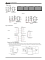
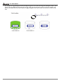
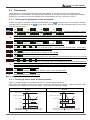
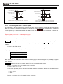
Timer/Counter/Tachometer User Manual CTA USER MANUAL FORWORD This user manual provides handy instructions for the operation of Delta CTA series. The detailed operational instructions help the user to easily locate the functions they would like to acquire. In addition, this user manual also helps sales and engineering staff to understand more about the advantages of Delta CTA series and assist the users to operate CTA as well as getting familiar with its functions. The date of the latest update is shown in the bottom left of the page. CHAPTER ONE: BASIC INSTRUCTIONS 1.1 Features 4 1.2 Ordering Information 4 1.3 Specifications 4 1.4 Display, Indicators & Keys 5 1.5 Dimensions 5 1.6 Terminals Definition 5 1.7 Default Settings 7 1.8 Easy DIP Switch Setup 7 CHAPTER TWO: FUNCTIONS 2.1 Ti m e r 9 2.2 Counter 14 2.3 Tachometer 19 2.4 Timer + Counter (Mixed Mode) 22 CHAPTER THREE: 3.1 2007-05-09 APPLICATIONS On Cut-To-Length Machine 23 -2- © DELTA ELECTRONICS, INC. ALL RIGHTS RESERVED CTA USER MANUAL NOTES How to use CTA correctly… To avoid misaction caused by interference, please make sure if you isolate the I/O wiring when I/O wiring and power cable or high-voltage cable in the same wiring tube. If possible, use a separate tube for the I/O wiring. Make sure that you place the sensor, other input devices, signal cables and CTA away from the interference source. It will require 200ms after CTA is switched on for the activation of the internal power and default value reset. CTA may not operate normally during this period of time. © DELTA ELECTRONICS, INC. ALL RIGHTS RESERVED -3- 2007-05-09 CTA USER MANUAL CHAPTER ONE: BASIC INSTRUCTIONS 1.1 Features Delta CTA series is the 3-in-1 timer, counter and tachometer with the following features: Can be a timer, counter, or tachometer and can operate in timer + counter mixed mode. Offers voltage input (PNP) or non-voltage input (NPN). The Pre-Scale function allows the input pulses to be displayed in their actual units. Counting speeds available: 1/30/200/1K/5K/10K cps. Maximum: 10K cps. The counting can be conducted in millisecond, second, minute, minute/second and hour/minute/second. Output 1 contains relay output and transistor output. The two types of outputs can be enabled concurrently. Offers total counting and batch counting. “Reset” and “Lock” keys for more convenient use. Offers 6-digit double-line LCD display. Offers easy DIP switch setup. Decimal point setup available. 1.2 Ordering Information There are currently two model types available: CTA4000A and CTA4100A, only differentiating in the type of output 2. CTA4 □00A 1 2 3 4 5 CTA: Delta Timer/Counter/Tachometer A series n Panel size 4: 48mm × 48mm o Output 2 0: Transistor p Preset stage 0: 2 preset stage q Communication 0: None \ Power supply A: AC100 ~ 240V 1: Relay 1.3 Specifications Power input Input voltage range Power consumption External power supply Display Input signal Output 1 Output 2 Dielectric strength Vibration resistance Shock resistance Ambient temperature Storage temperature Altitude Ambient humidity Pollution degree 2007-05-09 AC100 ~ 240V, 50/60Hz 85% to 110%, rated voltage Less than 10VA 12Vdc ±10%, 100mA Double-line, 6-digit LCD display Non-voltage input (NPN): ON impedance 1K ohm max. ON residual voltage: 2V max. Voltage input (PNP): High level: 4.5 to 30Vdc, Low level: 0 to 2Vdc Relay: SPST max.250Vac, 5A (resistance load) Transistor: NPN open collector. When 100mA /30Vdc, residual voltage = 1.5Vdc max. Relay: SPDT max.250Vac, 5A (resistance load) Transistor: NPN open collector. When 100mA /30Vdc, residual voltage = 1.5Vdc max. 2000Vac 50/60 Hz for 1 minute Without damage: 10 ~ 55Hz, amplitude = 0.75mm, 3 axes for 2 hours Without damage: drop 4 times, 300m/s2, 3 edges, 6 surfaces and 1 corner 0°C to +50°C -20°C to +65°C 2000m or less 35% to 85% RH (non-condensing) Degree 2 -4- © DELTA ELECTRONICS, INC. ALL RIGHTS RESERVED CTA USER MANUAL 1.4 Display, Indicators & Keys Reset 2 indicator Reset 1 indicator PV(Present Value) display Key protect 2 indicator Key protect 1 indicator SV(Set Value) display Output 2 indicator Output 1 indicator Timer function indicator Counter function indicator Tachometer function indicator Special function indicator Lock key Reset key Up/Down key Mode and number shift key PV: Red LCD SV and other display areas: Green LCD H M S: Time unit for the timer TOTAL: Total counting value BATCH: Batch counting value SET1 2: SV1 and SV2 1.5 Dimensions 1.6 Terminal Definition CTA combines the functions of timer, counter and tachometer; therefore, the definitions of input terminals in different modes are slightly different. CTA has 4 terminals ready for inputs. Take the pins in counter mode for example, 12 13 7 8 are for CP1 (A phase), CP2 (B phase) RST1 and RST2 inputs (see figure 1). The output terminals are for OUT1 and OUT2. OUT1 has two outputs, transistor output and relay output, and the two outputs operate concurrently. The type of OUT2 is determined by the model name. For CTA4000A, OUT2 only offers transistor output with inductive load protection diode (see figure 2). For CTA4100A, OUT2 only offers relay output (see figure 3). © DELTA ELECTRONICS, INC. ALL RIGHTS RESERVED -5- 2007-05-09 CTA USER MANUAL CTA4 series Counter CP1 CP2 Reset1 Reset2 Timer Gate Reset1 Start Tachometer CP1 Reset1 Timer + Counter CP1 Gate Reset1 Start Figure 1 Figure 2 Figure 3 Input connection: NPN PNP Output load PIN connection: 1. When CP1, CP2, RST1 and RST2 inputs are contact inputs, please set the input type as NPN. 2. When the previous device is an open collector type, the device can adopt the 12V power supply offered by CTA for the connection. (Relay Output) 2007-05-09 (Transistor Output) -6- © DELTA ELECTRONICS, INC. ALL RIGHTS RESERVED CTA USER MANUAL 1.7 Default Settings Tachometer Function Preset setting Select function Timer Timer mode Up (counting up) Output mode Sond1 Displayed unit S 001 (0.01) Pulse width of output 1 0.02sec Min. width of reset 20ms signal Input signal type NPN Select function Counter Counter mode Stage1 (1 stage) Input mode Up (counting up) Output mode F Counting speed 5K Position of decimal 0 (no decimals) point Pre-scale value 1.000 Save data while Clear switching off power Min. width of reset 20ms signal Input signal type NPN Timer + Counter Counter Timer There are 4 operation modes in CTA: timer, counter, tachometer and timer + counter. The table below offers the preset parameters for all functions. Function Select function Output mode Counting speed Position of decimal point Pre-scale value Delay time while switching on power Average of input data Min. width of reset signal Input signal type Select function Input mode of timer Output mode of timer Preset setting Tachometer 2Lo1Lo 5K 0 (no decimals) 1.000 (default) 0 (function disabled) 20ms NPN Mix(Timer +Counter) Up (counting up) Sond1 Displayed unit of timer S 001(0.01) Input mode of counter Up (counting up) Output mode of counter F Counting speed 5K Pulse width of output 1 Position of decimal point Pre-scale value Save data while switching off power Min. width of reset signal Input signal type 0.02sec 0 (no decimals) 1.000 (default) 0.0 (no delay) Clear 20ms NPN 1.8 Easy DIP Switch Setup The tables below are the DIP switches for each mode of CTA. Please be noted that in the “timer + counter” mode, setting up parameters by DIP switches are not allowed. Timer Switch Function 1 DIP switch 2 3 4 5 6 7 8 Timer mode Output mode Displayed unit Width of reset signal OFF ON Disabled Enabled Counting Counting up down See top-right table See bottom-right table 20ms © DELTA ELECTRONICS, INC. ALL RIGHTS RESERVED 1ms Switch 3 OFF ON OFF ON Switch 5 OFF ON OFF ON OFF ON OFF ON -7- Switch 4 OFF OFF ON ON Switch 6 OFF OFF ON ON OFF OFF ON ON Output mode Sond1 Sond2 Soffd Son Switch 7 OFF OFF OFF OFF ON ON ON ON Displayed unit 0.01 sec. 0.1 sec. 1 sec. min., 0.01 sec. min., 0.1 sec. 0.1 min. minute hr., min., sec. 2007-05-09 CTA USER MANUAL Counter Switch Function 1 DIP switch 2 3 4 5 6 7 8 OFF ON Disabled Enabled Counting Counting Counting mode up down See the table on Output mode the right Counting speed 30cps 10Kcps Reserved Input signal NPN PNP Width of reset signal 20ms 1ms Switch 3 OFF ON OFF ON Switch 4 OFF OFF ON ON Output mode F N C R Switch 3 OFF ON OFF ON Switch 4 OFF OFF ON ON Output mode Lo-Lo Lo-Hi Hi-Lo Hi-Hi Tachometer Switch 1 2 3 4 5 6 7 8 Function DIP switch Reserved OFF ON Disabled Enabled See the table on Output mode the right Counting speed 30Hz 10KHz Reserved Input signal NPN PNP Width of reset signal 20ms 1ms ※When Switch 1 is enabled (ON), the parameters can only be set up by Switch 1 ~ Switch 8 and cannot be modified in the system. If the parameters have to be set in the system, please disable Switch 1 (OFF). 2007-05-09 -8- © DELTA ELECTRONICS, INC. ALL RIGHTS RESERVED CTA USER MANUAL CHAPTER TWO: FUNCTIONS 2.1 Timer There are counting up and counting down modes in the timer. 2.1.1 Setting up the counting unit sec. sec. sec. min., sec. min., sec. min. min. hr., min., sec. 0.01 ~ 9,999.99 0.1 ~ 99,999.9 1 ~ 999,999 0.01 ~ 9,959.99 0.1 ~ 99,959.9 0.1 ~ 99,999.9 1 ~ 999,999 A unit = 10ms A unit = 0.1 sec. A unit = 1 sec. A unit = 0.01 sec. A unit = 0.1 sec. A unit = 0.1 min. A unit = 1 min. Max. counting = 9,999.99 secs. Max. counting = 99,999.9 secs. Max. counting = 999,999 secs. Max. counting = 5,999.99 secs. Max. counting = 59,999.9 secs. Max. counting = 99,999.9 mins. Max. counting = 999,999 mins. 1 ~ 995,959 A unit = 1 sec. Max. counting = 359,999 secs. (100 hrs.) hr., min. 1 ~ 999,959 A unit = 1 min. hr. 1 ~ 999,999 A unit = 1 hr. Max. counting = 35,999,999 secs. (10,000 hrs.) Max. counting = 699,999 hrs. 2.1.2 Setting up the parameters in the timer To enter the page for parameter setting of the timer, press in the main menu for more than 3 for more than 3 seconds under any of the parameter seconds. After the setup is completed, press page you are in and return to the main menu. x x x x z Select functions: There are 4 modes in CTA, (left to right) timer, counter, tachometer and timer + counter. x x z Select timer mode: counting up and counting down x x x x x x x x x x x x Select output modes: There are 12 output modes in the timer. The user can choose the mode that best meets z the demand. See 2.1.3 for more details. x x z x x x x x x Select display unit: the min. unit 10ms ~ the max. unit hour are selectable x z x x x Select pulse width of output 1: The default output time is 0.02 second. When the parameter is set to 0.00 second, the output status will continue. x x z Select min. width of reset signal: The default value is 20ms; can be set to 1ms. x x z Select input signal types: NPN and PNP Back to Top © DELTA ELECTRONICS, INC. ALL RIGHTS RESERVED -9- 2007-05-09 CTA USER MANUAL 2.1.3 Setting up output mode of the timer There are 12 modes in the timer for different control demands from the user. The default output time of the 12 modes is 0.02 second. If you wish the system to keep the operation of the output, please set the output time to 0.00 second. Power signal Start signal Signal On Delay 1 (Sond1) Pause signal The start signal is in rising-edge trigger mode and starts to time after the rising edge is triggered until the set time for output. During the execution of clear signal, the timer is reset and waits for the start signal to restart the timing. Clear signal t Output signal t SV Up 0 SV Down 0 Signal On Delay 1 Power signal Start signal Signal On Delay 2 (Sond2) Pause signal Clear signal Output signal t t SV Up 0 SV Down The start signal starts to time when enabled (Hi) until the set time for output. During the execution of clear signal and start signal being disabled (Lo), the timer is reset and waits for the start signal to restart the timing. 0 Signal On Delay 2 Power signal Start signal Signal Off Delay (Soffd) Pause signal The output starts when the start signal is at rising-edge trigger. When the start signal is at falling edge, the timer will start to time until the set time for disabling the output. If the clear signal is enabled (Hi) when the start signal is at rising edge, the output will stop immediately. Clear signal Output signal SV Up 0 SV Down 0 Signal Off Delay 2007-05-09 - 10 - © DELTA ELECTRONICS, INC. ALL RIGHTS RESERVED CTA USER MANUAL Power signal Signal On (Son) Start signal The start signal starts to time and output when the rising edge is triggered and the clear signal is not executed. When the set time is reached, the timer will return to the default value and the output will be disabled. Pause signal Clear signal Output signal SV Up If clear signal is received during the execution of the timer, the timer will return to the default value and the output will stop. 0 SV Down 0 Signal On Power signal Power On Delay (Pond) Start signal CTA immediately starts to time after the power is switched on. During the timing, the start signal and pause signal are able to stop the timing. When the set time is reached, the output will be enabled and the timing will stop. Pause signal Clear signal t Output signal t t SV Up When the clear signal is executed, the timing will be reset until the execution of clear signal is completed and the timing will start again. 0 SV Down 0 Power On Delay Power signal Start signal Power On Delay Hond (PondH) Pause signal Clear signal Output signal t t SV Up Down 0 t t Same as “Pond” The only difference is whether the current value is held when the power is switched off. In PondH, After the power is switched on, the timer will resume the timing. SV 0 Power On Delay Hold © DELTA ELECTRONICS, INC. ALL RIGHTS RESERVED - 11 - 2007-05-09 CTA USER MANUAL Power signal Power signal Start signal Start signal Pause signal Pause signal Clear signal Clear signal Output signal Output signal t t t Repeat Cycle timer output not set as 0 SV SV Up Up 0 SV SV Down Down 0 Repeat Cycle timer output set as 0 Repeat Cycle (RCY) Output in cycle. When the output time is selected as 0 (left: continuous output), the output of the first timing cycle will not be executed. When the set time is reached, the timing will be reset and restarted and the output will be enabled until the next cycle. When the output time is not 0 (right), the output time will be different from when the output time is 0. Power signal Power signal Start signal Start signal Pause signal Pause signal Clear signal Clear signal Output signal Output signal t SV t SV Up Up 0 Down t 0 SV SV Down 0 0 Repeat Cycle Hold RCYH timer output not set as 0 Timer output set as 0 Repeat Cycle Hold (RCYH) Same as “RCY” The only difference is whether the current value is held when the power is switched off. In RCYH, After the power is switched on, the timer will resume the timing. 2007-05-09 - 12 - © DELTA ELECTRONICS, INC. ALL RIGHTS RESERVED CTA USER MANUAL Power signal Repeat Cycle2 (RCY2) Start signal Output in cycle. Pause signal The start signal starts to time and output when the rising edge is triggered and the clear signal is not executed. When the set time SV2 is reached, the output will be disabled and the timer continue to time until the set time SV1 is reached and the timer will start the timing again. Clear signal Output signal SV1 SV2 Up 0 Down SV1 SV2 0 Repeat Cycle 2 Power signal Start signal Signal Cumulate (SCON) Pause signal Latched cumulate timer. When the start signal is enabled (Hi), the timing will start until the set time is reached for output. During the execution of clear signal, the timer is reset and waits for the start signal to be enabled (Hi) again. CTA will resume the timing. Clear signal Output signal SV Up Down 0 SV 0 Signal Cumulate Power signal Signal Twin ON-Start (STON) Start signal Output in cycle. Pause signal Clear signal The start signal starts to time and output when the rising edge is triggered and the clear signal is not executed. When the set time SV2 is reached, the output will be disabled and the timer will restart the timing from 0 until it reaches the set time SV1 and turn Off. Output signal SV1 Up SV2 Down SV1 SV2 0 0 Signal Twin ON-Start Power signal Signal Twin Off-Start (STOFF) Start signal Output in cycle. Pause signal The start signal starts to time when the rising edge is triggered and the clear signal is not executed. When the set time SV1 is reached, the output will be On and the timer will restart the timing from 0 until it reaches the set time SV2. The timer will then start the timing again and disable the output. Clear signal Output signal Up SV1 SV2 0 SV1 Down SV2 0 Signal Twin OFF-Start © DELTA ELECTRONICS, INC. ALL RIGHTS RESERVED - 13 - 2007-05-09 CTA USER MANUAL 2.2 Counter The counter functions include: 1-stage counting, 2-stage counting, batch counting, total counting and dual counting. 1-stage counting 2-stage counting Batch counting Total counting Dual counting Only 1 SV is allowed. 2 SVs and 2 PVs are allowed. When the PV equals SV, output 2 will be enabled and the batch PV will plus 1. This will repeat until the batch PV reaches batch SV and output 1 will be enabled. There is only one SV in total counting. When the PV equals SV, the output will be enabled. The clear signal will then be enabled, and the counting will restart and PV will be accumulated into the total counter. For addition and subtraction of CP1 and CP2. 2.2.1 Setting up the parameters in the counter To enter the page for parameter setting of the counter, press in the main menu for more than 3 for more than 3 seconds under any of the parameter seconds. After the setup is completed, press page you are in and return to the main menu. x x z x z x x x x x x Select input modes: counting up, counting down, command counting up/down, individual counting up/down, quadrature input x x x x x x x x x x x x Select output modes: CTA offer 11 output modes, among which mode S, T and D are only valid with input modes Ud_A, Ud_b and Ud_C. See 2.2.2 for more details. x z x Select counter functions: 1-stage counting, 2-stage counting, batch counting, total counting, dual counting. x z x Select functions: There are 4 modes in CTA, (left to right) timer, counter, tachometer and timer + counter. x z x x x x x x Select counting speed: Maximum 10Kcps; others 5K, 1K, 200, 30 and 1cps. x x z Pulse width of output 1: The default output time is 0.02 second. When the parameter is set to 0.00 second, the output status will continue. z Pulse width of output 2: This parameter is adjustable according to different output modes selected. If the output mode is C, the default output time will be 0.02 second. When the parameter is set to 0.00 second, the output status will continue. x x z x x x x Set up the position of decimal point: 0 (no decimal point), 1 (one digit after decimal point), 2 (two digits after decimal point), 3 (three digits after decimal point) x z Set up pre-scale value: 1.000 (default 1:1) Range: 0.001 ~ 99.999 x z Save the data while switching off the power: When SAVE is selected, the PV will be saved; when CLEAR is selected, the PV will not be saved. x z x x Set up minimum width of reset signal: Default = 20ms; 1ms is also selectable. x x Select input signal types: NPN and PNP z Back to Top 2007-05-09 - 14 - © DELTA ELECTRONICS, INC. ALL RIGHTS RESERVED 2.2.2 Setting up input mode of the counter CTA offers 5 counting modes: counting up, counting down, command counting up/down, individual counting up/down and quadrature input. The minimum signal width of the counting speed: Counting speed 1cps 30cps 1Kcps 5Kcps 10Kcps Minimum signal width 500ms 16.7ms 0.5ms 0.1ms 0.05ms Counting up CP1: Counter input H CP1 L CP2: Counter input prohibited A CP2 H L Prohibit A CP1: Counter input prohibited H CP1 L A CP2: Counter input A Prohibit H CP2 L 5 4 Present Value 3 Present Value 2 3 2 1 4 1 0 0 Note: A has to be larger than width of min. Input signal 0 0 Note: A has to be larger than width of min. Input signal Counting down CP1: Counter input CP1 H L CP2 H L n CP2: Counter input prohibited A Prohibit A A CP2 H L Prohibit CP2: Counter input A n n-1 n-1 Present Value CP1: Counter input prohibited CP1 H L Present Value n-2 n-3 n-4 0 Note: A has to be larger than width of min. Input signal Command counting up/down n-2 n-3 n-4 n-5 0 Note: A has to be larger than width of min. Input signal CTA USER MANUAL Individual counting up/down Quadrature input CP1 H L B B B B CP2 H L 3 Present Value 2 2 1 1 0 0 Note: 0 has to be larger than width of 1/2 min. input signal. B 2.2.3 Setting up output mode of the counter CTA offers 11 output modes in the counter for 1-stage and 2-stage counting. When 1-stage output is selected, output 2 and output 1 will be operated in the same way. Input mode Up Input mode Up Output mode setting F Down Up/Down A, B, C Output mode setting RESET 999999 SV2 K Down Up/Down A, B, C RESET 999999 SV2 SV1 SV1 0 0 T T T T T T T T T T T T T T T T T T T T OUT1 OUT1 OUT2 OUT2 N P RESET 999999 SV2 SV1 SV1 0 0 T T T T T TT T T T T Q RESET 999999 T T T TT T T T T TT T T T T T T T T T RESET 999999 SV2 SV2 SV1 SV1 0 0 T T T T T T T T T T T T T OUT1 OUT1 OUT2 OUT2 A RESET T RESET 999999 999999 SV2 SV2 SV1 SV1 0 0 T T T T T TT T T T OUT1 T T T T OUT1 OUT2 OUT2 2007-05-09 T T OUT2 OUT2 R T OUT1 OUT1 C RESET 999999 SV2 - 16 - © DELTA ELECTRONICS, INC. ALL RIGHTS RESERVED CTA USER MANUAL Input mode Up/Down A, B, C Output mode setting S RESET 999999 SV2 SV1 0 OUT1 OUT2 T RESET 999999 SV2 SV1 0 OUT1 OUT2 D RESET 999999 SV2 SV1 0 OUT1 OUT2 2.2.4 Batch counting When the PV equals SV, output 2 will be enabled and the batch PV will plus 1. The PV will be cleared and the counting will restart. This will repeat until the batch PV reaches batch SV and output 1 will be enabled. For example: A fruit packaging machine has to package 100 boxes with 5 fruit in each box. In this case, set the SV as 5 and batch SV as 100. When the belt starts to package the fruit, output 2 will inform the motor of the moving and plus 1 to the batch counter. After repeating the process for 100 times, i.e. 500 fruit of 100 boxes are packaged, output 1 will be enabled and notify the user by sound, light or indicator that the packaging has been completed. 2.2.5 Total counting There is only one SV in total counting. When the PV equals SV, the output will be enabled. If the clear signal is enabled now, the counting will restart and PV will be accumulated into the total counter. © DELTA ELECTRONICS, INC. ALL RIGHTS RESERVED - 17 - 2007-05-09 CTA USER MANUAL For example: An egg packaging machine packages 5 eggs as a unit. After the 5 eggs are packaged, output 1 and output 2 will be enabled at the same time and the motor will be informed to move to the next package. This process will repeat and record the number of eggs packaged in the total counter for the user to check at any time. 2007-05-09 - 18 - © DELTA ELECTRONICS, INC. ALL RIGHTS RESERVED CTA USER MANUAL 2.3 Tachometer The tachometer in CTA measures the pulse width and displays the current frequency. The measuring and displaying unit in the tachometer is frequency (Hz); therefore, if you want the value to be displayed in rotation speed (rpm), you have to convert the frequency into rotation speed. See 2.3.3 for how to convert. 2.3.1 Setting up the parameters in the tachometer To enter the page for parameter setting of the tachometer, press in the main menu for more than 3 seconds. for more than 3 seconds under any of the parameter page you are in and After the setup is completed, press return to the main menu. x z x x x Select functions: There are 4 modes in CTA, (left to right) timer, counter, tachometer and timer + counter. x x x x z Select output modes: There are 4 output modes, 2Lo1Lo, 2Lo1Hi, 2Hi1Lo and 2Hi1Hi. For example, when you select 2Hi1Lo, and assume the first set value is 100 (2Hi) and the second 50 (1Lo), the output value of the tachometer will be below 100 (2Hi) and above 50 (1Lo) and CTA will not perform an output. If the set value exceeds the range, CTA will perform an output. z Select rotation speed: Maximum 10Kcps; others 5K, 1K, 200, 30 and 1cps. z Set up the position of decimal point: 0 (no decimal point), 1 (one digit after decimal point), 2 (two digits after decimal point), 3 (three digits after decimal point) z Set up pre-scale value: 1.000 (default 1:1) Range: 0.001 ~ 99.999 z Set up the delay time after switching on the power: 0.0 (default). The tachometer will start to run when the set delay time is due after the power is switched on. Setup range: 0.1 ~99.9 seconds. z Set up average value of the input filter: The average value is for making the present value detected by the tachometer more stable. The setup range is 0 ~ 3 (1 = 2 data, 2 = 4 data, 3 = 8 data). For example, if you select “3”, the system will average the 8 present values from the tachometer to make the present value displayed on the screen more stable. z Set up minimum width of reset signal: Default = 20ms; 1ms is also selectable. x x x x x x x x x x x x x x x x x x x x Select input signal types: NPN and PNP. Back to Top z 2.3.2 Setting up output mode of the tachometer There are 4 output modes in the tachometer, 2Lo1Lo, 2Lo1Hi, 2Hi1Lo and 2Hi1Hi. Take 2Lo1Lo for example, assume the set value of output 2 is 100 and 50 for output 1, when the present value measured by the tachometer is below 50, output 1 and output 2 will both be enabled. 2Lo1Lo OUT2 set value 2Lo1Hi OUT2 set value (LO-LO) Measurement value Measurement value OUT1 set value OUT1 set value OUT1 OUT1 OUT2 OUT2 Measurement value (LO-HI) OUT1 set value : OUT1 ON OUT2 set value : OUT2 ON © DELTA ELECTRONICS, INC. ALL RIGHTS RESERVED Measurement value Measurement value - 19 - OUT1 set value : OUT1 ON OUT2 set value : OUT2 ON 2007-05-09 CTA USER MANUAL 2Hi1Lo OUT2 set value 2Hi1Hi OUT2 set value Measurement value Measurement value OUT1 set value OUT1 set value OUT1 OUT1 OUT2 Measurement value Measurement value (HI-HI) (HI-LO) OUT2 OUT1 set value : OUT1 ON OUT2 set value : OUT2 ON Measurement value Measurement value OUT1 set value : OUT1 ON OUT2 set value : OUT2 ON 2.3.3 Calculating the unit of rotation speed The tachometer is able to receive an open collector type input signal of maximum 10KHz and displays the unit as Hz on the screen of the tachometer. Therefore, if you wish the rotation speed to be displayed in rpm, you have to convert Hz into rpm by an equation and fill the obtained value into rotation speed in rpm on the screen. of the tachometer to display the The conversion equation: Frequency (Hz) × Pre-scale = Rotation Speed (rpm) Pre-scale = 60/N ※N = Number of pulses per revolution (ppr) Example 1: Connecting Delta servo drive with a servo motor and measure the current rotation speed by CTA The built in encoder in Delta servo motor is 10,000ppr with four phases, OA, OB, OA and OB . Every phase is 2,500ppr. Pre-scale = 60/2,500 = 0.024 At this time, the servo inputs 240rpm, equivalent to the tachometer receiving 10KHz currently. Frequency and rotation speed of CTA connected to Delta servo drive: Frequency 10KHz 5KHz 1KHz 200Hz Rotation speed 240rpm 120rpm 24rpm 4.8rpm Note: OA and OB of Delta ASD servo motor A and B series only support differential signals. OZ (10,000ppr) supports open collector. Example 2: Measuring the current rotation speed of the AC fan motor through a sensor Figure 1: 1 revolution of the fan equals 1 pulse; therefore Pre-scale = 60/N = 60/1 = 60 At this time, the sensor detects the speed and sends it back to tachometer. Assume the value displayed on the screen is 2,700rpm, F × 60/1 = 2,700 F = 45Hz Figure 2: 1 revolution of the fan equals 3 pulses; therefore Pre-scale = 60/N = 60/3 = 20 2007-05-09 - 20 - © DELTA ELECTRONICS, INC. ALL RIGHTS RESERVED CTA USER MANUAL At this time, the sensor detects the speed and sends it back to tachometer. Assume the value displayed on the screen is 3,200rpm, F × 60/3 = 3,200 F = 160Hz Figure 1 © DELTA ELECTRONICS, INC. ALL RIGHTS RESERVED Figure 2 - 21 - 2007-05-09 CTA USER MANUAL 2.4 Timer + Counter (Mixed Mode) CTA offers timer + counter mode. The timer corresponds to OUT1 (output 1) and the counter to OUT2 (output2). In this mode, the timer and counter both have a phase signal input; therefore, part of the functions will be limited. For example, there are 12 output modes for the timer of CTA, but only 8 output modes available in the timer + counter mode (Rcy2, Scon, Ston and Stoff are not available). In addition, the mixed mode only offers input modes Up and Down for the counter and S, T, D are no longer available in the output modes. See 2.4.1. for how to set up the parameters in the mixed mode. 2.4.1 Setting up the parameters in the “timer + counter” To enter the page for parameter setting of the timer + counter, press in the main menu for more than 3 for more than 3 seconds under any of the parameter page you seconds. After the setup is completed, press are in and return to the main menu. x z x x z z z z x x Select timer mode: counting up and counting down x x x x x x x x Select output modes: There are 8 output modes. The user can choose the mode that best meets the demand. See 2.1.3 for more details. x x x x x x x x x x Select display unit: the min. unit 10ms ~ the max. unit hour are selectable x z x Select functions: There are 4 modes in CTA, (left to right) timer, counter, tachometer and timer + counter. x Select input modes: Only counting up and counting down are available. See 2.2.2 for more details. x x x x x x x x Select output modes: Same as the output modes of the counter except for S, T, D. See 2.2.3 for more details. x x x x x z Select counting speed: Maximum 5Kcps; others 1K, 200, 30 and 1cps. z Select pulse width of output 1: The default output time is 0.02 second. When the parameter is set to 0.00 second, the output status will continue. z Pulse width of output 2: This parameter is adjustable according to different output modes selected. If the output mode is C, the default output time will be 0.02 second. When the parameter is set to 0.00 second, the output status will continue. z Set up the position of decimal point: 0 (no decimal point), 1 (one digit after decimal point), 2 (two digits after decimal point), 3 (three digits after decimal point) z Set up pre-scale value: 1.000 (default 1:1) Range: 0.001 ~ 99.999 z Save the data while switching off the power: When SAVE is selected, the PV will be saved; when CLEAR is selected, the PV will not be saved. z Set up minimum width of reset signal: Default = 20ms; 1ms is also selectable. x x x x x x x x x x x x x x x Select input signal types: NPN and PNP z Back to Top 2007-05-09 - 22 - © DELTA ELECTRONICS, INC. ALL RIGHTS RESERVED CTA USER MANUAL CHAPTER THREE: APPLICATIONS 3.1 On Cut-To-Length Machines The machine adopts the counter function in CTA and acquires the feedback signal from the encoder for measuring the actual operation distance. When the set distance is reached, the output signal will enable the knife for the cutting. Example: We will simulate the action above by using CTA and Delta ASDA-A. Parameter settings x z Select function: Counter z Select counting mode: 1-stage counting (only 1 set value). If you need 2 set values, select 2-stage counting. z Select input mode: Quadrature input z Select output mode: C; the counting will automatically restart when the set value is reached. x x x x z Select counting speed: The maximum 10K z Set up pulse width of output 2: 0.02 second z Set up the position of decimal point: 0 (no decimal point) z Set up pre-scale value: 0.056 z Save the data while switching off the power: Select CLEAR, and the PV will not be saved. z Set up min. width of reset signal: select default value 20ms. x x x x x x Select input signal type: NPN z Back to Top © DELTA ELECTRONICS, INC. ALL RIGHTS RESERVED - 23 - 2007-05-09 CTA USER MANUAL Output Wiring Connect 0V, CP1 (phase A) and CP2 (phase B) to CN1 terminal on ASDA-A servo drive Assume The set value in the CTA counter is 160mm. When the counting reaches 160mm, an output signal will be given to the knife for the cutting. See figure 2. In the figure, we can see the diameter of the roller is 44.8mm Delta encoder 1 phase = 2,500ppr Calculate the pre-scale value π D = Prescale ppr π: 3.1416 D: diameter of the roller ppr: number of pulses per revolution of the encoder Prescale = π D = 3.1416 x 44.8 = 0.056mm/pulse 2500 ppr When the value in CTA = 2,858 2858 x 0.056 = 160mm (actual moving distance) 100mm Figure 1 Figure 2 SV has to be 160mm 2007-05-09 The servo drive stops at 100mm on the ruler before its operation - 24 - © DELTA ELECTRONICS, INC. ALL RIGHTS RESERVED CTA USER MANUAL Ruler at 60mm Figure 3 Figure 4 When the tachometer reaches 160mm, the output will be enabled. © DELTA ELECTRONICS, INC. ALL RIGHTS RESERVED - 25 - The distance moved is 160mm. The ruler stops at 60mm. 2007-05-09