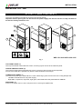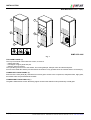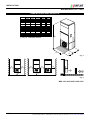
1
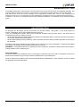
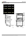
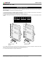
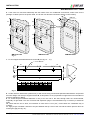
INSTALLATION
Wall Mounted 0121…0661
MONOBLOC EXTERNAL UNITS
FOR INSTALLATION IN SHELTERS
AND PREFABRICATED BUILDINGS
WMA/WMF
0121- 0181 - 0251 - 0281 - 0331
0551 - 0661
INSTALLATION MANUAL
GB
© UNIFLAIR 2000
Monobloc Wall Mounted Unit - WMA/WMF 0121-0181-0251-0281-0331-0551-0661 - Rev. 2.0. - Date: 18-07-2000 EN
1 (22)
INSTALLATION
Wall Mounted 0121…0661
Before installing or carrying out any operation on the unit, carefully read the
instructions and safety regulations in this manual and on the notices on the
unit.
Some characteristics of special-order units may be different from those
described in this manual.
UNIFLAIR ITALIA S.r.l.
Via dell’Industria, 10
35020 BRUGINE (Padova) Italy
Tel. +39 (0)49 9713211
Fax. +39 (0)49 5806906
Internet: www.UNIFLAIR.com
E-Mail: [email protected]
Release:
2.0
Date:
18 - 07 - 2000
Checked by:
2 (22)
Monobloc Wall Mounted Unit - WMA/WMF 0121-0181-0251-0281-0331-0551-0661 - Rev. 2.0. - Date: 18-07-2000 EN
INSTALLATION
Wall Mounted 0121…0661
Index
Page
Symbols
Important warnings
Access to main components
Transport and movement
Dimensions and weights
Positioning the unit
Air distribution
Mounting the unit
Connecting the condensate drain
Electrical connections
Recommended power supply cable sections and line fuses
Temperature and humidity sensor (optional)
3
4
5
7
8
9
10
13
15
16
20
22
SYMBOLS
SYMBOL
MEANING
DANGER
SYMBOL
MEANING
MOVING COMPONENTS
IMPORTANT WARNING
HOT SURFACE
BURNING
–
LIVE COMPONENTS – RISK OF
ELECTRIC SHOCK
SHARP SURFACES
RISK
OF
COMPONENTS SENSITIVE TO
ELECTROSTATIC DISCHARGE
Monobloc Wall Mounted Unit - WMA/WMF 0121-0181-0251-0281-0331-0551-0661 - Rev. 2.0. - Date: 18-07-2000 EN
3 (22)
INSTALLATION
Wall Mounted 0121…0661
This unit has been subjected to risk analysis under EC Directive 98/37/CEE (89/392/CEE): it is built to perform the
functions for which it was designed without risk as long as the installation, operation and maintenance of the
unit are all carried out according to the instructions in this manual and on the labels on the unit.
The risks which are particularly important for the safety of the user are marked with the danger symbol.
IMPORTANT WARNINGS
This unit contains refrigerant circuits under pressure, live electrical components, hot surfaces, sharp edges (e.g. the
coil) and rotating devices (e.g. fans). Before opening the unit, disconnect it from the electrical power supply.
All service and maintenance operations must be performed when the unit is off and must be done by
qualified and experienced personnel who are aware of the necessary precautions.
In any case, all safety legislation of the installation location must be followed.
In the event of fire, water and other conductive substances must not be used to put out the fire near live electrical
components. This warning must be displayed on notices in the unit installation location.
If the refrigerants used come into contact with fire they decompose, forming acids and other irritants. The smell of
these substances, even at concentrations below danger levels, gives enough warning to allow evacuation of the
area at risk.
Electronic components are sensitive to electrostatic discharges from the human body. Touch an earth contact
before handling any electronic component.
Make sure that the power supply voltage corresponds to the value shown on the data plate.
4 (22)
Monobloc Wall Mounted Unit - WMA/WMF 0121-0181-0251-0281-0331-0551-0661 - Rev. 2.0. - Date: 18-07-2000 EN
INSTALLATION
Wall Mounted 0121…0661
ACCESS TO MAIN COMPONENTS
The unit is accessible on all sides by removing the relevant panels.
Important: before opening the unit disconnect the power supply and wait for the fans to stop and wait for
the electric heating element to cool.
A
D
Q.E.
B
T
S
C
WM* 0121-0181-0251-0281-0331
Fig. 1
TOP FRONT PANEL (A)
The Top Front Panel is fixed with two screws; removing it gives access to the electrical panel.
CENTRE FRONTAL PANEL (B)
The Centre Frontal Panel is fixed with two screws; removing it gives access to the evaporator.
Access to the radial fan is possible only after the internal sheet is removed (D).
LOWER FRONT PANEL (C)
The lower front panel (C) is fixed with four screws. Removing it gives access to the free cooling damper and:
- Left Side: terminal block for unit power supply;
- Right Side: compressor, dryer filter, sight glass, thermostat valve and pressostats AP AND BP.
SIDE PANEL (S)
Access to the damper motor is via the side panel shown in the diagram (WMF units).
Monobloc Wall Mounted Unit - WMA/WMF 0121-0181-0251-0281-0331-0551-0661 - Rev. 2.0. - Date: 18-07-2000 EN
5 (22)
INSTALLATION
Wall Mounted 0121…0661
A
D
Q.E.
B
B
C
C
WMF 0551-0661
Fig. 2
TOP FRONT PANEL (A)
The Top Front Panel is fixed with two screws; to remove:
- release the bolts;
- hold edges of upper panel and pull;
- raise the panel to remove.
This operation gives access to the airfilter; free-cooling damper, damper motor and electrical panel.
Access to the radial fan and the pre-heat electrical resistors is only possible once the internal sheet is removed (D).
LOWER LEFT FRONT PANEL (B)
Removal of the front panel (B), fixed with four screws gives access to the compressor, dehydrator filter, sight glass,
thermostat valve and pressostats AP and BP.
LOWER RIGHT FRONT GRILLE (C)
The grille is fixed with five screws. Removing it gives access to the axial fan motor protected by a metal grille.
6 (22)
Monobloc Wall Mounted Unit - WMA/WMF 0121-0181-0251-0281-0331-0551-0661 - Rev. 2.0. - Date: 18-07-2000 EN
INSTALLATION
Wall Mounted 0121…0661
TRANSPORT AND MOVEMENT
The unit should not be turned on its back or upside-down, or exposed to the weather and should be taken as
near as possible to the installation location before removing the cardboard packing and the pallet.
The unit can be lifted:
- with a fork-lift, placing the forks in the appropriate slots of the pallet;
- with straps passed under the unit, making sure that they do not put pressure on the upper rim of the unit.
The unit must be stored, preferably in its packing, under cover and protected from excessive humidity (< 90% R.H.)
and temperature (< 50°C).
WARNING: Units with alluminium pannelling, once positioned must be removed of packaging. Extended exposure
to the sun can cause problems in package removal.
The dimensions and weight of the unit with packaging are given below:
N
O
mm
WMF
0121
WMF
0181
WMF
0251
WMF
0281
WMF
0331
M
O
N (*)
740
740
1020
1020
1020
495
495
570
570
570
2020
2020
1970
1970
1970
kg
150
167
210
210
230
mm
WMF
0551
WMF
0661
M
O
N (*)
1140
1140
kg
M
665
665
2284
2284
320
340
(*) without pallet
Fig. 3
The symbols applied to the unit’s packaging conform to ISO7000; they are explained in the table below.
SYMBOL
MEANING
FRAGILE: handle with care.
PROTECT
AGAINST
MOISTURE: the packaged unit
must be stored in a dry place.
SYMBOL
MEANING
THIS SIDE UP shows
orientation of the unit.
+50°C
-20°C
the
TEMPERATURE LIMITS: the unit
must not be stored outside these
limits.
CENTRE OF GRAVITY: shows
the centre of gravity of the
packaged unit.
NO HOOKS: do not use hooks to
lift the packed unit.
KEEP AWAY FROM HEAT: the
unit must be kept away from heat
sources.
DO NOT STACK
RECEIVING THE UNIT
When the unit arrives, check that it is complete and in perfect condition; notify the carrier immediately in writing
of any damage that might have been caused in transit.
Monobloc Wall Mounted Unit - WMA/WMF 0121-0181-0251-0281-0331-0551-0661 - Rev. 2.0. - Date: 18-07-2000 EN
7 (22)
INSTALLATION
Wall Mounted 0121…0661
DIMENSIONS AND WEIGHTS
mm
A1
B
C
Sx (*)
Dx (*)
H (*)
E (*)
kg
WM
0121
WM
0181
WM
0251
WM
0281
WM
0331
650
650
930
930
930
1790
1790
1940
1940
1940
400
400
450
450
450
300
300
300
300
300
400
400
400
400
400
300
300
300
300
300
1500
1500
1500
1500
1500
135
152
190
190
210
B
(*) see par. ‘WORKING SPACE’
A1
E
C
Fig. 4
Sx
Dx
H
Sx
Dx
Dx
H
Fig. 5
WM* 0121-0181-0251-0281-0331
8 (22)
Monobloc Wall Mounted Unit - WMA/WMF 0121-0181-0251-0281-0331-0551-0661 - Rev. 2.0. - Date: 18-07-2000 EN
INSTALLATION
Wall Mounted 0121…0661
mm
WMF
0551
WMF
0661
A1
B
C
Sx (*)
Dx (*)
H
E (*)
1050
1050
2250
2250
kg
625
625
300
300
300
300
300
300
1500
1500
300
320
B
(*) see par. ‘WORKING SPACE’
C
A1
E
Fig. 6
Sx
Dx
H
H
Fig. 7
WM* 0551-0661
POSITIONING THE UNIT
WM units are designed to be installed outdoors. However, it is recommended to protect the unit from rain, snow or
water falling from drains or gutters.
♦ The unit must be perfectly vertical with a maximum slope of 6-7 mm: a levelling defect can cause spillage from
the condensate tray.
♦ Do not install the unit less than 200 metres from the sea or near spas with sulphurous springs. Make sure that
the unit cannot take in air which contains vapours of inflammable or greasy substances.
♦ The air flow taken in by the fans via the condenser coil must not be obstructed in order not to reduce the
efficiency of the unit and to avoid the unit stopping because of the intervention of the compressor’s safety
functions;
♦ If the installation location is windy, it is advised to choose a protected area since the condensate axial fans have
limited pressure (not greater than 10 Pa). See fig 5. and 7.
WORKING SPACE
Monobloc Wall Mounted Unit - WMA/WMF 0121-0181-0251-0281-0331-0551-0661 - Rev. 2.0. - Date: 18-07-2000 EN
9 (22)
INSTALLATION
Wall Mounted 0121…0661
To facilitate maintenance, leave at least 1,5m free space in front of the unit as shown in the diagram (point E). This
minimum distance allows the expulsion of external air for condensation and the aspiration of air for free-cooling.
N.B.:Side access to the unit is only necessary on the right side of models 0121…0331 for the replacing of the
damper servomotor; it is not necessary for other maintenance operations or access to electrical panels and wires.
A distance of ‘D’ and ‘S’ is strongly advised to allow maximium ventilation of condensate across the lateral cahrge
grilles.
AIR DISTRIBUTION
Air discharge into and intake from the environment can be either directly - with grilles - or via ducting (Check in
section "TECHNICAL DATA" the available pressure of air flow.
If the air is distributed via grilles, these must correspond accurately with the holes made in the wall of the air
conditioned environment, making sure that:
• the air discharge grille (the upper grille) has a double row of directable slats to control the direction of the airflow
on both the vertical and horizontal plane;
• the air intake grille has a wide passage in order to minimise the loss of load; the intake grille slats do not need to
be directable.
If ducting is used for the distribution and/or intake of air it must be of the correct dimensions; ‘Technical Data’ tables
give details of le portate e pressure drop characteristic of each unit.
WARNING: it is essential the airflow is completely free from obstruction, insufficient outflow reduces airflow and the
cooling capacity of the conditioning unit.
AIR FLOW HOLES
To allow air flow into the climatised room it is necessary to make two holes in the wall in the position of the unit of
dimensions indicated in Fig.8; air holes must be completely free of any obstructions.
Figura 9. Shows the rear panel of the unit with pricipal dimensions. Models 0551 - 0661 aspiration and air flow holes
are protected with fixed metal grilles.
10 (22)
Monobloc Wall Mounted Unit - WMA/WMF 0121-0181-0251-0281-0331-0551-0661 - Rev. 2.0. - Date: 18-07-2000 EN
INSTALLATION
Wall Mounted 0121…0661
mm
WM
0121
A1
B1
C1
D1
E1
F1
G1
H1
L1
A2
B2
C2
E2
F2
L2
WM
0181
WM
0251
WM
0281
WM
0331
WM
0551
WM
0661
50
30
128
430
470
404
850
880
1138
70
70
135
230
280
240
230
280
340
710
990
1110
1790
1940
2250
570
850
840
45
25
123
420
460
394
845
875
1133
240
290
250
240
290
350
580
860
850
A1
E1
A2
E2
B1
B2
F2
L2
F1
H1
D1
L1
D1
C2
L2
Rear of the unit
C1
G1
Outside wall of the
air conditioned
environment
Fig. 8
Monobloc Wall Mounted Unit - WMA/WMF 0121-0181-0251-0281-0331-0551-0661 - Rev. 2.0. - Date: 18-07-2000 EN
G1
Fig. 9
11 (22)
INSTALLATION
Wall Mounted 0121…0661
Fix rubber seals around the mouths of the air intake and discharge to ensure an airtight fit; 18-20mm thick selfadhesive closed-cell neoprene rubber tape is recommended.
Apply a layer of builder’s silicone to the joint between the top cover of the unit and the wall, to prevent rain from
entering the gap.
SILICONE
SEALANT
NEOPRENE
TAPE
Fig. 10
EXTERNAL AIR INTAKE (0121…0331 models)
WM 0121…0331 units are available in the following versions with different
external air intakes:
• WMA; the lower front panel is completely closed (fig. 11. - panel C);
• WMF, with external air intake for the free-cooling cycle and motorised
control damper.
The quantity of external air is variable from a minimum value (set using
the microprocessor control) to 100% of the air discharged into the air
conditioned environment. It is taken in via a special opening mounted
on the front panel (fig. 11. -panel C2) - which contains a washable
metal pre-filter to protect against the entry of leaves and insects.
The expulsion of air from the air conditioned environment is via an
aperture connected to the lower lateral grilles (D).
C
C2
D
Fig. 11
12 (22)
Monobloc Wall Mounted Unit - WMA/WMF 0121-0181-0251-0281-0331-0551-0661 - Rev. 2.0. - Date: 18-07-2000 EN
INSTALLATION
Wall Mounted 0121…0661
MOUNTING THE UNIT
WM units are mounted on the outside wall of the air conditioned environment and fixed using screws through the
two side flanges.
Before installing the unit observe the following instructions:
1. Check that the wall is of suitable material and strength to support the weight of the unit and to cope with the
(relatively minimal) vibrations of the refrigerant compressor;
2. Make intake and discharge holes in wall (see par. 'AIR DISTRIBUTION';
3. Make 8 holes (F) in the wall (10 for 0551-0661 models) necessary for fixing the unit; recommended diameter
12mm;
mm
WM
0121
a
b
c
d
WM
0181
WM
0251
WM
0281
WM
0331
WM
0551
WM
0661
100
100
125
100
100
125
15
15
15
530
580
400
c
c
a
a
d
d
d
d
d
d
F
F
d
b
b
E
E
D
WM*0121…0331
D
WM*0551-0661
Fig. 12.
4. Fix rubber seals around the mouths of the air intake and discharge to ensure an airtight fit; 18-20mm thick selfadhesive closed-cell neoprene rubber tape is recommended (see fig. 10.);
5. Channel airflow making use or rigid or flexible ducts;
Monobloc Wall Mounted Unit - WMA/WMF 0121-0181-0251-0281-0331-0551-0661 - Rev. 2.0. - Date: 18-07-2000 EN
13 (22)
INSTALLATION
Wall Mounted 0121…0661
6. If the units are connected electrically with the inside of the air conditioned environment, make holes for the
passage of cables (one for the power cable, one for the user terminal connection and the control cables);
70
Ø 30 mm
264
502
367
Ø 30 mm
55
Ø 36 mm Ø 22 mm
57
40
40
92
45
575
785
105
45
85
WM*0121-0181
Fig. 13.
WM*0251-0331
WM*0551-0661
7. Fix unit support bracket D with three screws E (see fig. 12. - 14.);
n. 3 FORI Ø8 mm
40
10
d
45°
40
d
50
10
D
L
mm
L
d
WM
0121
WM
0181
WM
0251
WM
0281
WM
0331
600
880
260
400
WM
0551
WM
0661
Fig. 14.
8. Lift the unit from below with a pallet truck (or with a hoist using canvas belts passed underneath the unit) and fit
the lower flange over the lip of support bracket D; in this phase it is very important to support the unit on all sides to
prevent it swinging or falling;
9. Fit screws E (recommended diameter 8 mm) to fix the unit to the wall; through bolts are recommended,
especially on light walls. The use of screws with expansion plugs is recommended only on masonry or brickwork
walls.
10. Check that the unit is level; an inclination of more than 6-7 mm (0.5°) could cause the condensate tray to
overflow;
11. Apply a layer of builder’s silicone to the joint between the top cover of the unit and the wall to prevent rain from
entering the gap (see fig. 10.).
14 (22)
Monobloc Wall Mounted Unit - WMA/WMF 0121-0181-0251-0281-0331-0551-0661 - Rev. 2.0. - Date: 18-07-2000 EN
INSTALLATION
Wall Mounted 0121…0661
CONNECTING THE CONDENSATE DRAIN
The condensate tray is located at the base of the evaporate coil; the condensate drains from the tray via a flexible
tube (included with the unit) behind the condensate coil.
The flexible tube has a bend which functions as a siphon and must not be removed
The flexible tube drains the condensate across the lower unit grille: it is possible to connect it to the main water
drain of the building via a plastic tube with 25mm internal diameter and a minimum slope of 1%.
Condensate drain
Condensate coil
REAR OF THE UNIT
Monobloc Wall Mounted Unit - WMA/WMF 0121-0181-0251-0281-0331-0551-0661 - Rev. 2.0. - Date: 15-05-2000 EN
Fig. 15.
15 (22)
INSTALLATION
Wall Mounted 0121…0661
ELECTRICAL CONNECTIONS
Correct and accurate electrical connections, carried out in compliance with local regulations, are
extremely important for the prevention of accidents and for ensuring long, trouble-free operations.
ACCESS TO THE ELECTRICAL PANELS AND PRELIMINARY CHECKS
Before working on the electrical parts of the unit, make sure that there is no power supply to the
unit and that the switch on the electrical panel is off (in the “O” position)
Check that the mains voltage corresponds to the nominal data of the unit(voltage, phases, frequency) shown on the
electrical panel.
Power supply voltage must be within -10% e +6% the nominal value. In tri-phase units the difference between the
phases must be less than 2%: unit operation with power supplies outside these limits may invalidate the guarentee.
Units with a three-phase power supply of 400 V need a neutral cable.
INSTALLING THE POWER SUPPLY CABLE
- 0121-0331 models (fig. 16.a.):
depending on the requirements of the installation, the power
and command circuit cables can enter the unit in one of three
locations:
a. from the rear, through the back of the unit (point A); if the
unit is connected to the inside of the air conditioned
environment;
b. from the side (point B) for external connections;
c. from below (point C).
- 0551-0661 models (fig. 16.b.):
insert the power cables through the provided holes at the rear
of the unit. The cables can be inserted directly to the power
supply using the sheath.
The three holes on the right are for the installation of the power
cables; the three holes on the left permit the installation of the
signal cables to be connected to the circuit mP20 or the q.e.
terminal block.
The table “RECOMMENDED POWER SUPPLY CABLE
SECTIONS AND LINE FUSES” contains the recommended
sections for the power supply and the size of fuses to mount
before the mains switch.
A
B
C
Fig. 16.a
Power
cables
REAR OF THE UNIT
Signal
cables
Fig. 16.b
IMPORTANT WARNING
Seperate the signal cables from the power cables by using different routes (where possible) or by grouping the two
sets of cables seperately. Make sure that the power supply and auxiliary control cables are as far as possible from
electric components. After opening the pre-drilled holes on the rear of the unit, protect the cable passages with
avoid contact with sharp surfaces.
16 (22)
Monobloc Wall Mounted Unit - WMA/WMF 0121-0181-0251-0281-0331-0551-0661 - Rev. 2.0. - Date: 15-05-2000 EN
INSTALLATION
Wall Mounted 0121…0661
CONNECTING THE POWER SUPPLY CABLES
-
0121-0331 MODELS: Locate the terminal blocks positioned to the left of the compressor;
WM* 0121-0181-0251
L1
N
PE
UPS
(Opt.)
L10
N10
WM* 0331
L1
L2
L3
N
PE
UPS
(Opt.)
-
L10
N10
Fig. 17.a.
0121-0331 MODELS: (special versions) on a few special unit versions the terminal block beside the
compressor is non supplied and the power supply cables are therefore directly connected to the terminals of the
mains switch.
Power supply cable
I
O
IM2
IG
Fig. 17.b.
Monobloc Wall Mounted Unit - WMA/WMF 0121-0181-0251-0281-0331-0551-0661 - Rev. 2.0. - Date: 15-05-2000 EN
17 (22)
INSTALLATION
Wall Mounted 0121…0661
-
0551-0661 models: Locate the mains switch IG found inside the electrical circuit;
UPS
(Opt.)
IG
I
O
L10
N10
L1
L2
L3
N
PE
IM2
IM1
Fig. 17.c.
- Fix the cable terminals to the mains switch and secure the screws; connection of the yellow/green earth wire using
the terminal ‘PE’ is compulsory.
WM units can be fitted with a double power supply:
• main 400V/3N/50Hz line for:
- compressor;
- condensor fans;
- electrical heating elements;
• UPS 230V/1/50Hz line for:
-evaporator fans;
- damper motor;
- mP20 microprocessor circuit and terminal.
Units can also be specified with double power supply with emergency 48 Vcc
CONNECTING THE USER TERMINAL
-
Connect the User Terminal mP20 to the Base Board found inside the electrical panel. In a few units the terminal
mP20 can be positioned beside the electrical panel (see figure18); it is fixed on a hinged bracket that allows
access to the mP20 board.
Q.E.
Q.E.
WM*
0121-0181
0251-0281-0331
Fig. 18.a.
18 (22)
WM* 0551-0661
Fig. 18.b.
Monobloc Wall Mounted Unit - WMA/WMF 0121-0181-0251-0281-0331-0551-0661 - Rev. 2.0. - Date: 15-05-2000 EN
INSTALLATION
Wall Mounted 0121…0661
RECOMMENDED POWER SUPPLY CABLE SECTIONS AND LINE FUSES
Power cable is not supplied by UNIFLAIR ITALIA Srl and must be appropriately dimensioned by the installer. For
short distances ( < 30 m ) the recommended sections are shown in the table below:
MAIN 230V/1N/50Hz LINE
MODEL
LINE
FUSE (a)
UPS 230V/1N/50Hz LINE (opt.)
MODEL
LINE
WM* 0121
2x4+4PE
40A
WM* 0121
2x1.5
WM* 0181
2x4+4PE
40A
WM* 0181
2x1.5
WM* 0251
2x4+4PE
40A
WM* 0251
2x1.5
WM* 0281
2x4+4PE
40A
WM* 0281
2x1.5
MAIN 400V/3N/50Hz LINE
MODEL
LINE
FUSE (a)
UPS 230V/1N/50Hz LINE (opt.)
MODEL
LINE
WM* 0331
4x4+4PE
25A
WM* 0331
2x1.5
WM* 0551
4x4+4PE
40A
WM* 0551
2x1.5
WM* 0661
4x4+4PE
40A
WM* 0661
2x1.5
Monobloc Wall Mounted Unit - WMA/WMF 0121-0181-0251-0281-0331-0551-0661 - Rev. 2.0. - Date: 15-05-2000 EN
19 (22)
INSTALLATION
Wall Mounted 0121…0661
TEMPERATURE AND HUMIDITY SENSOR (optional)
The optional temperature and humidity sensors ASXC must be installed as shown in the unit’s electrical diagrams.
ASW
80
126 mm
Fig. 20.
Temperature setting is done on the user termianl (see MP20 instruction manual); adjustment is at intervals of 0.1°C;
maximum adjustment is between –9.9°C and +9.9 °C.
20 (22)
Monobloc Wall Mounted Unit - WMA/WMF 0121-0181-0251-0281-0331-0551-0661 - Rev. 2.0. - Date: 15-05-2000 EN
INSTALLATION
Wall Mounted 0121…0661
Monobloc Wall Mounted Unit - WMA/WMF 0121-0181-0251-0281-0331-0551-0661 - Rev. 2.0. - Date: 15-05-2000 EN
21 (22)
INSTALLATION
UNIFLAIR ITALIA S.r.l.
Via dell’industria, 10
35020 BRUGINE (Padova) - Italy
Tel. +39 (0)49 9713211
Fax +39 (0)49 5806906
22 (22)
Internet: www.UNIFLAIR.com
E-mail: [email protected]
Manual code @ digit: 06MM010 @ 00B0200
Wall Mounted 0121…0661
Monobloc Wall Mounted Unit - WMA/WMF 0121-0181-0251-0281-0331-0551-0661 - Rev. 2.0. - Date: 15-05-2000 EN