1
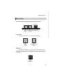
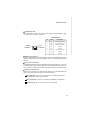
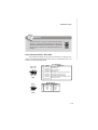
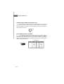
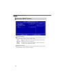
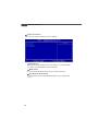
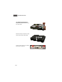
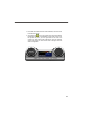
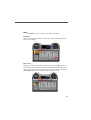
Axis 700
Axis 700 Lite
MS-6427 (V1.X) Barebone
G52-64271X1
FCC-B Radio Frequency Interference Statement
This equipment has been tested and
found to comply with the limits for a
class B digital device, pursuant to
part 15 of the FCC rules. These limits
are designed to provide reasonable
protection against harmful interference in a residential installation. This equipment
generates, uses and can radiate radio frequency energy and, if not installed and
used in accordance with the instruction manual, may cause harmful interference to
radio communications. However, there is no guarantee that interference will not
occur in a particular installation. If this equipment does cause harmful interference to
radio or television reception, which can be determined by turning the equipment off
and on, the user is encouraged to try to correct the interference by one or more of the
measures listed below.
=Reorient or relocate the receiving antenna.
=Increase the separation between the equipment and receiver.
=Connec the equipment into an outlet on a circuit different from that to which the
receiver is connected.
=Consult the dealer or an experienced radio/television technician for help.
Notice 1
The changes or modifications not expressly approved by the party responsible for
compliance could void the user’s authority to operate the equipment.
Notice 2
Shielded interface cables and A.C. power cord, if any, must be used in order to
comply with the emission limits.
VOIR LA NOTICE D’INSTALLATION AVANT DE RACCORDER AU RESEAU.
Micro-Star International
Axis 700
This device complies with Part 15 of the FCC Rules. Operation is subject to the
following two conditions:
(1) this device may not cause harmful interference, and
(2) this device must accept any interference received, including interfer ence that
may cause undesired operation.
ii
Trademark
All trademarks are the properties of their respective owners.
Intel® and Pentium® are registered trademarks of Intel Corporation.
PS/2 and OS ® /2 are registered trademarks of International Business Machines
Corporation.
W indows ® 95/98/2000/NT/XP are registered trademarks of Microsoft Corporation.
Netware® is a registered trademark of Novell, Inc.
Award® is a registered trademark of Phoenix Technologies Ltd.
AMI® is a registered trademark of American Megatrends Inc.
U.S. Patent Numbers
4,631,603; 4,819,098; 4,907,093; 5,315,448; and 6,516,132.
This product incorporates copyright protection technology that is protected by U.S.
patents and other intellectual property rights. Use of this copyright protection technology must be authorized by Macrovision, and is intended for home and other limited
viewing uses only unless otherwise authorized by Macrovision. Reverse engineering
or disassembly is prohibited.
Revision History
Revision
Revision History
Date
v1.0
First release
August 2006
Copyright Notice
T he material in this document is the intellec tual property of M ICRO-STAR
INTERNATIONAL. W e take every care in the preparation of this document, but no
guarantee is given as to the correctness of its contents. Our products are under
continual improvement and we reserve the right to make changes without notice.
iii
Safety Instructions
1.
Always read the safety instructions carefully.
2.
Keep this User’s Manual for future reference.
3.
Keep this equipment away from humidity.
4.
Lay this equipment on a reliable flat surface before setting it up.
5.
The openings on the enclosure are for air convection hence protects the
equipment from overheating. DO NOT COVER THE OPENINGS.
6.
Check power supply rating: 100-240V~, 3-1.5A, 60-50Hz.
7.
Place the power cord such a way that people can not step on it. Do not
place anything over the power cord.
8.
Always Unplug the Power Cord before inserting any add-on card or module.
9.
All cautions and warnings on the equipment should be noted.
10.
Never pour any liquid into the opening that could damage or cause electrical
shock.
11.
If any of the following situations arises, get the equipment checked by service
personnel:
- The power cord or plug is damaged.
- Liquid has penetrated into the equipment.
- The equipment has been exposed to moisture.
- The equipment does not work well or you can not get it work according to
User’s Manual.
- The equipment has dropped and damaged.
- The equipment has obvious sign of breakage.
12.
DO NOT LEAVE THIS EQUIPMENT IN AN ENVIRONMENT UNCONDITIONED,
STORAGE TEMPERATURE ABOVE 400 C (1020F), IT MAY DAMAGE THE
EQUIPMENT.
CAUT ION:
Danger of explos ion if battery is inc orrec tly replac ed.
Replace only with the same or equivalent type recommended by the
manufacturer.
iv
Warning:
1. For every changes in powercordˇ¦s usage, please use an approved power
cord with condition greater or equal to H05VV-F,3G , 0.75mm2.
2. Internal part is hazardous moving parts, please keep fingers and other
body parts away.
3. For pluggable equipment, the socket-outlet shall be installed near the
equipment and shall be easily accessible.
4. Do not disable the protective earth pin from the plug, the equipment must
be connected to an earthed mains socket-outlet.
v
WEEE Statement
vi
vii
viii
CONTENTS
Chapter 1. Getting Started...................................................................................1-1
Mainboard Specifications..............................................................................1-2
System Configuration....................................................................................1-4
Chapter 2. Hardware Setup..................................................................................2-1
Mainboard Layout.........................................................................................2-2
Memory..........................................................................................................2-3
Introduction to DDRII SDRAM...............................................................2-3
Installing DDRII Modules........................................................................2-3
Power Supply................................................................................................2-4
ATX 20-Pin Power Connector: ATXPWR..............................................2-4
Front Panel....................................................................................................2-5
Audio Ports..........................................................................................2-5
USB Ports.............................................................................................2-5
Rear Panel.....................................................................................................2-6
Connectors....................................................................................................2-8
ATA 133 IDE Connector: IDE1...............................................................2-8
Serial ATA Connectors: SATA1/SATA2...............................................2-9
Fan Power Connector: SYSFAN1......................................................2-10
CD-In Connector: CD_IN......................................................................2-10
Front Panel Audio Connector: JAUD..................................................2-10
Front Panel Connectors: JFP1/JFP2....................................................2-11
Chassis Intrusion Switch Connector: JCI1.........................................2-12
Front USB Connectors: J3/J4/J5.........................................................2-12
Wake On LAN Connector: J9.............................................................2-13
Jumper...........................................................................................................2-14
Clear CMOS Jumper: JBAT1.............................................................2-14
Slot................................................................................................................2-15
PCI Slot.................................................................................................2-15
Chapter 3. BIOS Setup.............................................................................................3-1
Entering Setup...........................................................................................3-2
Control Keys........................................................................................3-3
Getting Help..........................................................................................3-3
General Help <F1>...............................................................................3-3
The Main Menu............................................................................................3-4
Standard CMOS Features...........................................................................3-6
Advanced BIOS Features...........................................................................3-9
Advanced Chipset Features.......................................................................3-12
Integrated Peripherals.................................................................................3-15
ix
Power Management Setup.........................................................................3-19
PNP/PCI Configurations................................................................................3-23
H/W Monitor.................................................................................................3-25
Cell Menu.....................................................................................................3-27
Load Optimized Defaults.............................................................................3-28
BIOS Setting Password..............................................................................3-29
Chapter 4. System Assembly...............................................................................4-1
Overview.....................................................................................................4-2
Installation Tools....................................................................................4-2
Sc rews.................................................................................................4-2
Checking the Items................................................................................4-3
Installation Procedures.................................................................................4-4
Removing Top Cover...........................................................................4-4
Removing Optical Disk Drive................................................................4-5
Removing Card Reader.......................................................................4-6
Removing Riser Card...........................................................................4-7
Removing Hard Disk Drive...................................................................4-7
Installing Hard Disk Drive......................................................................4-8
Installing Riser Card..............................................................................4-8
Installing Card Reader.........................................................................4-9
Installing Optical Disk Drive..................................................................4-9
Installing Memory Modules...................................................................4-10
Restoring Chassis Cover.....................................................................4-12
Installing Footstand...............................................................................4-13
Appendix A. VIA VT1618 Audio.............................................................................A-1
Installing the Audio Driver............................................................................A-2
Installation for Windows 98SE/ME/2000/XP........................................A-2
Software Configuration...............................................................................A-4
Speaker................................................................................................A-4
Mixer....................................................................................................A-5
Speaker Test.......................................................................................A-6
Information...........................................................................................A-6
Hardware Setup.........................................................................................A-7
Connecting the Speakers...................................................................A-7
2-Channel Mode for Stereo-Speaker Output.......................................A-7
4-Channel Mode for 4-Speaker Output...............................................A-8
6-Channel Mode for 4-Speaker Output...............................................A-9
x
Chapter 1
Getting Started
Congratulations for purchasing Axis 700 (MS-6427)
barebone. Axis 700 barebone is your best Slim PC
choice. W ith the fantastic appearance and ultra-small
form factor, it can easily be set anywhere. The feature packed platform also gives you an exciting PC
experience.
M S-6427 Barebone
Mainboard Specifications
Processor Support
-
VIA ® C7 1GHz / 21x21mm nano BGA2 package
TDP max 1.2GHz @12W
Supports VRM mobile (down to 0.7V)
Thermal design margin up to 100。 c Tcase
3D instructions SSE / SSE2 / SSE3
Security Features RGN / AES / SHA-1
Supported FSB
- 400 / 533 MHz
Chipset
- North Bridge: VIA ® CN700 chipset
- South Bridge: VIA ® VT8237R+ chipset
M emory Support
- Supports DDRII 400 / 533 SDRAM (2GB Max)
- 1 DDRII DIMM (240pin / 1.8V)
LAN
- Supports PCI LAN 10/100 Fast Ethernet by VIA ® VT6103L
Audio
- Chip integrated by VIA ® VT1618
- Flexible 5.1-channel audio with jack sensing
- Compliant with AC97 2.3 spec
IDE
- One IDE port by VT8237R+
- Supports Ultra DMA 66/100/133 mode
- Supports PIO, Bus Master operation mode
SATA
- Supports two SATA ports by VT8237R+
- Supports storage and data transfers at up to 150MB/s
RAID
- SATA1-2 supports RAID 0/ 1 or JBOD mode by VT8237R+
1-2
Getting Started
Connectors
Back Panel
- 1 PS/2 mouse port
- 1 PS/2 keyboard port
- 2 serial ports (COMA and COMB)
- 2 USB 2.0 ports
- 1 LAN jack
- 3 flexible audio jacks
- 1 S-Video port (for standard only)
- 1 DVI port (for standard only)
- 1 VGA oort
On-Board Pinheaders
- 3 USB 2.0 pinheaders
- 1 audio pinheader
Slots
- 1 PCI slot
- Supports 3.3V/ 5V PCI bus Interface
Form Factor
- Mini-ITX (17 cm X 17 cm)
M ounting
- 4 mounting holes
1-3
M S-6427 Barebone
System Configuration
Front View
1. Mic-In (pink)
2. Headphone-Out (green)
3. USB 2.0 ports x 2
4. Power Button
5. HDD LED
1-4
6.
7.
8.
9.
Optical Drive Eject/ Close Button
Card Reader Drive (optional)
Power LED
Optical Drive (optional)
Getting Started
Rear View
(Standard Version)
1.
2.
3.
4.
5.
6.
7.
PS/2 Keyboard (purple)
PS/2 M ouse (green)
DVI Port (for standard only)
VGA Port (D-Sub15)
S-Video (for standard only)
USB 2.0 Ports
Serial Ports
8. Mic-In (pink)
9. Line-Out (green)
10. Line-In (blue)
11. Power Jack
12. Ventilation Hole
13. LAN Jacks (RJ45)
14. Expansion Slots
1-5
M S-6427 Barebone
Rear View
(Lite Version)
1.
2.
3.
4.
5.
6.
1-6
PS/2 Keyboard (purple)
PS/2 M ouse (green)
VGA Port (D-Sub15)
USB 2.0 Ports
Serial Ports
Mic-In (pink)
7. Line-Out (green)
8. Line-In (blue)
9. Power Jack
10. Ventilation Hole
11. LAN Jacks (RJ45)
12. Expansion Slots
Getting Started
Chassis Design
- Dimension: 363mm (D) x 300mm (W) x 72mm (H)
- Minimized screw structure
- Detachable bay housing
- Multiple ventilation holes
Back
Side
Bottom
1. System Ventilation Hole
3. CPU Fan Ventilation Hole
2. Power Supply Ventilation Hole
4. System Ventilation Hole
1-7
M S-6427 Barebone
sharp
System Picture
Ventilation Hole
Ventilation
Po w e r
Hole
Supply
System
Po w e r
Fan
Supply Fan
Ventilation
Hole
Front Panel
1-8
Getting Started
System Air Flow Direction
Ventilation Hole
Ventilation
Hole
Po w e r
Supply
Po w e r
Supply Fan
Ventilation
Hole
Front Panel
After the installation is completed, please keep
other objects away from the ventilation hole at
least 2.5cm and above. Do not block the ventilation hole.
1-9
Chapter 2
Hardware Setup
This chapter provides you with the information about
hardware s etup procedures . W hile doing the
installation, be careful in holding the components
and follow the installation procedures. For some
components, if you install in the wrong orientation,
the components will not work properly.
Use a grounded wrist strap before handling computer components. Static electricity may damage
the components.
ONLY FOR SERVICE PERSONEL
Always unplug the power cord before inserting any add-on card or module.
M S-6427 Barebone
Mainboard Layout
Top : mouse
Bottom:KB
ATXPWR
VIA
C7
SYSFAN1
Top : VGA Port
Bottom: DIV Port (for standard only)
S-Video Out (for standard only)
VIA
CN700
DIMM1
VIA
VT1622A
Top: LAN Jack
Bottom: USB ports
VIA
VT6103L
J5
Top : COMA
Bottom: COMB
JCI1
J3
J4
T:MIC-In
M:Line- In
B:SS Out
VIA
VT8237R Plus
IDE1
VIA
VT1632A
JBAT1
SATA1 SATA2
BIOS
JAUD
CD_IN
VIA
VT1618
BATT
+
J9
JFP2
PCI 1
MS-7199 (V1.X) Mini-ITX Mainboard
2-2
JFP1
Hardware Setup
Memory
The mainboard provides one slot for 240-pins non-ECC DDRII DIMM, which
supports the memory size up to 2GB. For more information on compatible
components, please visit http://www.msi.com.tw/program/products/slim_pc/slm/
pro_slm_cpu_support.php
DDRII
240-pins, 1.8V
56 x 2 = 112-pins
64 x 2 = 128-pins
Installing DDRII Modules
1. The DIMM memory module has only one notch on the center and will only fit in
the right orientation.
2. Insert the DIMM memory module vertically into the DIMM slot. Then push it in
until the golden finger on the memory module is deeply inserted in the socket.
3. The plastic clip at each side of the DIMM slot will automatically close.
Important
You can barely see the golden finger if the module is properly
inserted in the socket.
Volt
Notch
2-3
M S-6427 Barebone
Power Supply
The mainboard supports ATX power supply for the power system. Before
inserting the power supply connector, always make sure that all components
are installed properly to ensure that no damage will be caused.
ATX 20-Pin Power Connector: ATXPWR
This connector allows you to connect to an power supply. To connect to
the power supply, make sure the plug of the power supply is inserted in the
proper orientation and the pins are aligned. Then push down the power supply
firmly into the connector.
Pin Definition
PIN
1
2
3
20
10
11
ATXPWR
1
4
5
6
7
8
9
10
SIGNAL
PIN
PINSIGNAL
3.3V
3.3V
11
12
3.3V
-12V
GND
5V
13
14
GND
PS_ON
GND
5V
15
16
GND
GND
GND
PW_OK
17
18
GND
-5V
5V_SB
19
20
5V
5V
12V
Important
1. Make sure that the connector is connected to proper ATX power
supplies to ensure stable operation of the mainboard.
2. Power supply of 130 watts (and above) is highly recommended
for system stability.
2-4
Hardware Setup
Front Panel
The Front Panel provides the following connectors:
Mic-In Headphone-Out USB Ports
(green)
(pink)
Audio Ports
These audio ports allow you to connect front audio devices.
Mic-In
(pink)
Headphone-Out
(green)
USB Ports
The mainboard provides a UHCI (Universal Host Controller Interface)
Universal Serial Bus root for attaching USB devices such as keyboard, mouse or
other USB-compatible devices. You can plug the USB devices directly into these
connectors.
USB Ports
2-5
M S-6427 Barebone
Rear Panel
The Rear Panel provides the following connectors:
Mouse
(green)
VGA
S-Video
(for standard only) LAN
Line-In
Line-Out
Keyboard
(purple)
DVI
(for standard only)
USB Ports
Serial Ports
MIC-In
M ouse/Keyboard Connector
The standard PS/2® mouse/keyboard DIN connector is for a PS/2 ® mouse/
keyboard.
VGA Connector
The DB15-pin female connector is provided for VGA monitors.
DVI Connector (for standard only)
The DVI (Digital Visual Interface) connector allows you to connect an LCD monitor.
It provides a high-speed digital interconnection between the computer and its
display device. To connect a LCD monitor, simply plug your monitor cable into the
DVI connector, and make sure that the other end of the cable is properly connected to your monitor (refer to your monitor manual for more information).
S-Video Connector (for standard only)
The S-Video connector allows users to connect display devices for component
video input/output. S-Video (Super-Video, sometimes referred to as Y/C Video,
or component video) is a video signal transmission in which the luminance signal
and the chrominance signal are transmitted separately to achieve superior picture clarity. The luminance signal (Y) carries brightness information, which defines the black and white portion, and the chrominance signal (C) carries color
information, which defines hue and saturation. An S-Video connection brings
better video quality than a composite/RCA connection.
2-6
Hardware Setup
LAN (RJ-45) Jack
The standard RJ-45 jack is for connection to single Local Area Network (LAN).
You can connect a network cable to it.
LAN (Optional)
Activity
Indicator
Link
Indicator
PIN
SIGNAL
DESCRIPTION
1
TDP
Transmit Differential Pair
2
TDN
Transmit Differential Pair
3
RDP
Receive Differential Pair
4
NC
Not Used
5
NC
Not Used
6
RDN
Receive Differential Pair
7
NC
Not Used
8
NC
Not Used
USB Port Connectors
The OHCI (Open Host Controller Interface) USB (Universal Serial Bus) root is for
attaching USB devices such as keyboard, mouse, or other USB-compatible
devices.
Serial Port Connectors
The mainboard offers two 9-pins male DIN connectors as serial ports. The ports
are 16550A high speed communication ports that send/receive 16 bytes FIFOs.
You can attach a serial mouse or other serial devices directly to the connectors.
Audio Port Connectors
These audio connectors are used for audio devices. You can differentiate the
color of the audio jacks for different audio sound effects.
Blue audio jack: Line-In in 5.1 channel mode, is used for external CD
player, tapeplayer or other audio devices.
Green audio jack: Line-Out, is a connector for speakers or headphones.
Pink audio jack: Mic-In, is a connector for microphones.
2-7
M S-6427 Barebone
Connectors
.
ATA133 IDE Connector: IDE1
The mainboard has a 32-bit Enhanced PCI IDE and Ultra DMA 66/100/133
controller that provides PIO mode 0~4, Bus Master, and Ultra DMA 66/100/133
function. You can connect hard disk drives, CD-ROM and other IDE devices.
The Ultra ATA133 interface boosts data transfer rates between the computer and the hard drive up to 133 megabytes (MB) per second. The new
interface is one-third faster than earlier record-breaking Ultra ATA/100 technology and is backwards compatible with the existing Ultra ATA interface.
IDE (Primary IDE Connector)
The first hard drive should always be connected to IDE1. IDE1 can connect a
Master and a Slave drive. You must configure second hard drive to Slave mode
by setting the jumper accordingly.
IDE1
Important
If you install two hard disks on cable, you must configure the
second drive to Slave mode by setting its jumper. Refer to the
hard disk documentation supplied by hard disk vendors for
jumper setting instructions.
2-8
Hardware Setup
Serial ATA Connectors: SATA1/SATA2
SATA1/SATA2 are high-speed Serial ATA interface ports. Each supports
1st generation serial ATA data rates of 150MB/s and is fully compliant with Serial
ATA 1.0 specifications. Each Serial ATA connector can connect to 1 hard disk
device.
Pin Definition
1
1
7
7
PIN
SIGNAL
PIN
SIGNAL
1
3
GND
RXP
2
4
RXN
GND
5
7
TXN
GND
6
TXP
SATA1/SATA2
Serial ATA cable
Take off the Dust Cover and
connect to the Hard Disk
Devices
Connect to SATA1/2
Important
Please do not fold the Serial ATA cable into 90-degree angle.
Otherwise, data loss may occur during transmission.
2-9
M S-6427 Barebone
Fan Power Connectors: SYSFAN1
The Fan Power Connectors support system cooling fan with +12V. It
supports 3-pins head connector. When connecting the wire to the connectors,
always take note that the red wire is the positive and should be connected to the
+12V, the black wire is Ground and should be connected to GND. If the mainboard
has a System Hardware Monitor chipset on-board, you must use a specially
designed fan with speed sensor to take the advantage of the CPU fan control.
+12V
SENSOR
GND
SYSFAN1
CD-In Connector: CD_IN
This connector is provided for CD-ROM audio.
R
GND
L
CD_IN
Front Panel Audio Connector: JAUD
The JAUD front panel audio connector allows you to connect to
the front panel audio and is compliant with Intel® Front Panel I/O Connectivity Design Guide.
Pin Definition
PIN
10
9
2
1
JAUD
2-10
SIGNAL
DESCRIPTION
1
2
AUD_MIC
AUD_GND
Front panel microphone input signal
Ground used by analog audio circuits
3
4
AUD_MIC_BIAS
AUD_VCC
Microphone power
Filtered +5V used by analog audio circuits
5
6
AUD_FPOUT_R
AUD_RET_R
Right channel audio signal to front panel
Right channel audio signal return from front panel
7
8
HP_ON
KEY
N/C
No pin
9
10
AUD_FPOUT_L
AUD_RET_L
Left channel audio signal to front panel
Left channel audio signal return from front panel
Hardware Setup
Important
If you don’t want to connect to the front audio header,
pins 5 & 6, 9 & 10 have to be jumpered in order to have
signal output directed to the rear audio ports. Otherwise,
the Line-Out connector on the back panel will not
function.
10
9
6
5
Front Panel Connector: JFP1/JFP2
The mainboard provides two front panel connectors for electrical connection to the front panel switches and LEDs. JFP1 is compliant with Intel® Front
Panel I/O Connectivity Design Guide.
Pin Definition
PIN
1
2
3
DESCRIPTION
HD_LED_P Hard disk LED pull-up
FP PWR/SLP MSG LED pull-up
HD_LED_N Hard disk active LED
4
5
FP PWR/SLP MSG LED pull-up
RST_SW_N Reset Switch low reference pull-down to GND
6
7
PWR_SW_P Power Switch high reference pull-up
RST_SW_P Reset Switch high reference pull-up
JFP1
8
9
PWR_SW_N Power Switch low reference pull-down to GND
RSVD_DNU Reserved. Do not use.
Speaker
+
+ -
PIN
1
Reset HEE
Switch LED
9
10
1
2
Power Power
Switch LED
SIGNAL
Pin Definition
2
1
8
7
Power LED
3
5
7
SIGNAL
GND
SLED
PLED
N/C
PIN
2
SIGNAL
SPK-
4
6
BUZ+
BUZ-
8
SPK+
JFP2
2-11
M S-6427 Barebone
Chassis Intrusion Switch Connector: JCI1
This connector is connected to a 2-pin chassis switch. If the chassis is
opened, the switch will be short. The system will record this status and show a
warning message on the screen. To clear the warning, you must enter the BIOS
utility and clear the record.
1
2
CINTRU
GND
JCI1
Front USB Connectors: J3/J4/J5
The mainboard provides three standard USB 2.0 pinheaders. USB 2.0
technology increases data transfer rate up to a maximum throughput of 480Mbps,
which is 40 times faster than USB 1.1, and is ideal for connecting high-speed
USB interface peripherals such as USB HDD, digital cameras, MP3 players,
printers, modems and the like.
Pin Definition
9
10
1
2
J3/J4/J5
2-12
PIN
SIGNAL
PIN
1
VCC
2
SIGNAL
VCC
3
USB0-
4
USB1-
5
USB0+
6
USB1+
7
GND
8
GND
9
Key (no pin)
10
USBOC
Hardware Setup
USB 2.0 Bracket (Optional)
Connect to J3/J4/J5
Important
Note that the pins of VCC and GND must be connected correctly to avoid possible damage.
Wake On LAN Connector: J9
This connector allows you to connect to a LAN card with W ake On LAN
function. You can wake up the computer via remote control through a local area
network.
MP_WAKEUP
3
GND
5VSB
1
J9
2-13
M S-6427 Barebone
Jumper
The motherboard provides the following jumpers for you to set the
computer’s function. This section will explain how to change your motherboard’s
function through the use of jumpers.
Clear CMOS Jumper: JBT1
There is a CMOS RAM onboard that has a power supply from external
battery to keep the system configuration data. W ith the CMOS RAM, the system
can automatically boot OS every time it is turned on. If you want to clear the
system configuration, use the JBAT1 (Clear CMOS Jumper ) to clear data. Follow the instructions below to clear the data:
1
1
1
3
3
3
JBAT1
Keep Data
Clear Data
Important
You can clear CMOS by shorting 2-3 pin while the system is
off. Then return to 1-2 pin position. Avoid clearing the CMOS
while the system is on; it will damage the mainboard.
2-14
Hardware Setup
Slot
PCI (Peripheral Component Interconnect) Slot
The PCI slot supports LAN cards, SCSI cards, USB cards, and other addon cards that comply with PCI specifications. At 32 bits and 33 MHz, it yields a
throughput rate of 133 MBps.
PCI Slot
Riser Card
2-15
BIOS Setup
Chapter 3
BIOS Setup
This chapter provides the information on the BIOS Setup
program and allows you to configure the system for
optimum use.
You may need to run the Setup program when:
An error message appears on the screen during the
system booting up, and requests you to run SETUP.
You want to change the default settings for customized features.
3-1
M S-6427 Barebone
Entering Setup
Power on the computer and the system will start POST (Power On Self Test)
process. W hen the message below appears on the screen, press <DEL> key
to enter Setup.
Press DEL to enter SETUP
If the message disappears before you respond and you still wish to enter
Setup, restart the system by turning it OFF and On or pressing the RESET
button. You may also restart the system by simultaneously pressing <Ctrl>,
<Alt>, and <Delete> keys.
Important
1. The items under each BIOS category described in this
c hapter are under c ontinuous update for better s ys tem
performance. Therefore, the description may be slightly different from the latest BIOS and should be held for reference
only.
2. Upon boot-up, the 1st line appearing after the memory count
Important
is the BIOS
version. It is usually in the format:
W7265IMS V1.0 060715 where:
1st digit refers to BIOS maker as A= AMI, W= AWARD, and
P= PHOENIX.
2nd - 5th digit refers to the model number.
6th digit refers to the chipset as I= Intel, N= nVidia, and V=
VIA.
7th - 8th digit refers to the customer as MS= all standard
customers.
V1.0 refers to the BIOS version.
060715 refers to the date this BIOS was released.
3-2
BIOS Setup
Control Keys
<↑>
Move to the previous item
<↓>
Move to the next item
<←>
Move to the item in the left hand
<→>
Move to the item in the right hand
<Enter>
Select the item
<Esc>
Jumps to the Exit menu or returns to the main menu from a submenu
<+/PU>
Increase the numeric value or make changes
<-/PD>
Decrease the numeric value or make changes
<F1>
General Help
<F5>
Previous Values
<F7>
Optimized Defaults
<F10>
Save & Exit Setup
Getting Help
After entering the Setup menu, the first menu you will see is the Main Menu.
Main M enu
The main menu lists the setup functions you can make changes to. You can
use the arrow keys (↑↓) to select the item. The on-line description of the
highlighted setup function is displayed at the bottom of the screen.
Sub-M enu
If you find a right pointer symbol (as
shown in the right view) appears to the
left of certain fields that means a submenu can be launched from this field. A sub-menu contains additional options
for a field parameter. You can use arrow keys ( ↑↓ ) to highlight the field and
press <Enter> to call up the sub-menu. Then you can use the control keys to
enter values and move from field to field within a sub-menu. If you want to
return to the main menu, just press the <Esc >.
General Help <F1>
The BIOS setup program provides a General Help screen. You can call up this
screen from any menu by simply pressing <F1>. The Help screen lists the
appropriate keys to use and the possible selections for the highlighted item.
Press <Esc> to exit the Help screen.
3-3
M S-6427 Barebone
The Main Menu
Standard CM OS Features
Use this menu for basic system configurations, such as time, date etc.
Advanced BIOS Features
Use this menu to setup the items of the special enhanced features.
Advanced Chipset Features
Use this menu to change the values in the chipset registers and optimize your
system’s performance.
Integrated Peripherals
Use this menu to specify your settings for integrated peripherals.
Power M anagement Setup
Use this menu to specify your settings for power management.
PnP/PCI Configurations
This entry appears if your system supports PnP/PCI.
H/W M onitor
This entry shows your PC health status.
Cell M enu
Use this menu to specify your settings for CPU/AGP frequency/voltage control
and overclocking.
3-4
BIOS Setup
Load Optimized Defaults
Use this menu to load the default values set by the mainboard manufacturer
specifically for optimal performance of the mainboard.
BIOS Setting Password
Use this menu to set the password for BIOS.
Save & Exit Setup
Save changes to CMOS and exit setup.
Exit Without Saving
Abandon all changes and exit setup.
3-5
M S-6427 Barebone
Standard CMOS Features
Date (mm:dd:yy)
This allows you to set the system to the date that you want (usually the current
date). The format is <day> <month> <date> <year>.
[Day]
Day of the week, from Sun to Sat, determined by BIOS. Read
only.
[M onth] The month from Jan. through Dec.
[Date]
The date from 1 to 31 can be keyed by numeric function keys.
[Year]
The year can be adjusted by users.
Time (hh:mm:ss)
This allows you to set the system time that you want (usually the current time).
The time format is <hour> <minute> <second>.
3-6
BIOS Setup
IDE Channel 0 Master/Slave
Press <+> or <-> to select the hard disk drive type. The specification of hard
disk drive will show up on the right hand according to your selection. Press
<Enter> for the sub-menu of each item:
LBA/Large M ode
This item allows you to enable or disable the LBA (Logical Block Address,
the logical block size in hard disk) mode.
DM A M ode
This item allows you to enable or disable the DMA (Direct Memory
Access) mode.
3-7
M S-6427 Barebone
System Information
Press <Enter> and the following sub-menu appears:
Total M emory
This item shows the memory size of your system. You cannot change
any values in the Total Memory fields (read only).
BIOS Version
This item shows the BIOS version of your system (read only).
CPU ID/uCode IO/Frequency
The three items show the CPU related information of your system (read
only).
3-8
BIOS Setup
Advanced BIOS Features
Quick Booting
Setting the item to [Enabled] allows the system to boot within 5 seconds since
it will skip some check items.
CPU Feature
Press <Enter> for the sub-menu of each item:
Thermal M anagement
This setting specifies the thermal technologies implemented in the Pentium
M processor.
TM2 Bus Ratio / TM2 Bus VID
These settings specify the multiplier and VID values used by the processor in TM2 (Thermal Monitor 2) mode.
3-9
M S-6427 Barebone
CPU L3 Cache
Level 3 cache is the extra cache built into motherboards between the microprocessor and the main memory. Located away from the CPU, the L3 cache is
slower than the L1 & L2 caches. This setting allows you to turn on or off the L3
cac he.
Boot to OS/2
This allows you to run the OS/2 operating system with DRAM larger than
64MB. When you choose [No], you cannot run the OS/2® operating system with
DRAM larger than 64MB. But it is possible if you choose [OS2].
Full Screen LOGO Show
This item enables you to show the company logo on the bootup screen. Settings are:
[Enabled] Shows a still image (logo) on the full screen at boot.
[Disabled] Shows the POST messages at boot.
IOAPIC Function
This field is used to enable or disable the APIC (Advanced Programmable
Interrupt Controller). Due to compliance with PC2001 design guide, the system
is able to run in APIC mode. Enabling APIC mode will expand available IRQ
resources for the system.
MPS Table Version
This field allows you to select which MPS (Multi-Processor Specification) version to be used for the operating system. You need to select the MPS version
supported by your operating system. To find out which version to use, consult
the vendor of your operating system.
Boot Sequence
The original IBM PCs loaded the DOS operating system from drive A (floppy
disk), so IBM PC-compatible systems are designed to search for an operating
system first on drive A, and then on drive C (hard disk). However, modern
computers usually load the operating system from the hard drive, and may
even load it from a CD-ROM drive.
3-10
BIOS Setup
1st Boot Device/2nd Boot Device/3rd Boot Device
These items allow you to set the sequence of boot devices where
BIOS attempts to load the disk operating system.
Boot Other Device
Setting the option to [Enabled] allows the system to try to boot from
other device if the system fails to boot from the 1st/2nd/3rd boot device.
Hard Disk Boot Priority
Press [Enter] to enter a sub menu which shows every current hard drive
installed. Use [PageUp] or [PageDown] key to select the first boot hard disk.
3-11
M S-6427 Barebone
Advanced Chipset Features
DRAM Clock/Drive Control
Press <Enter> and the following sub-menu appears:
DRAM Clock
Use this field to configure the clock frequency of the installed DRAM.
Important
Be careful with the three hooks on the Front Panel. Remember
to remove them gently with hands or the damages can be made
easily.
3-12
BIOS Setup
DRAM Timing
The value in this field depends on performance parameters of the
installed memory chips (DRAM). Do not change the value from the
factory setting unless you install new memory that has a different
performance rating than the original DRAMs.
Read to Precharge (Trtp)
Time interval between a read and a precharge command.
Write to Read CM D (Twtr)
Minimum time interval between the end of write data burst and the start
of a column-read command. It allows I/O gating to overdrive sense
amplifiers before read command starts.
Write Recovery Time (Twr)
Minimum time interval between end of write data burst and the start of
a precharge command. Allows sense amplifiers to restore data to cells.
DRAM Command Rate
This setting controls the DRAM command rate. Select [1T Command]
allows DRAM singlal controller to run at 1T (T=clock cycles) rate. Select [2T Command] makes DRAM siganl controller run at 2T rate. [1T] is
faster than [2T].
AGP & P2P Bridge Control
Press <Enter> and the following sub-menu appears:
3-13
M S-6427 Barebone
CPU & PCI Bus Control
Press <Enter> and the following sub-menu appears:
PCI Master 0 WS Write
W hen [Enabled], writes to the PCI bus are executed with zero wait
states.
PCI Delay Transaction
The chipset has an embedded 32-bit posted write buffer to support
delay transactions cycles. Select [Enabled] to support compliance with
PCI specification version 2.1.
VLink mode selection
This item lets you choose the speed mode between the North Bridge &
South Bridge.
VLink 8X Support
This item enables or disables the 8X VLink Data Rate.
DRDY_Timing
This item allows you to select the DRDY Timing from Slowest, Default
and Optimize.
3-14
BIOS Setup
Integrated Peripherals
VIA OnChip PCI Device
Press <Enter> and the following sub-menu appears:
USB Controller
Select [Enabled] if your system contains a Universal Serial Bus (USB)
controller and you have USB peripherals.
OnChip EHCI Controller
This setting disables/enables the OnChip EHCI controller. The Enhanced
Host Controller Interface (EHCI) specification describes the register-level
interface for a Host Controller for the Universal Serial Bus (USB) Revision
2.0.
3-15
M S-6427 Barebone
Onboard LAN Controller
This setting controls the onboard LAN controller.
Onboard LAN Option ROM
The item enables or disables the initialization of the onboard LAN Boot
ROMs during bootup. Selecting [Disabled] will speed up the boot
process. Setting options: [Enabled], [Disabled].
USB Device Legacy Support
Set to [Enabled] if you need to use any USB 1.1/2.0 device in the
operating system that does not support or have any USB 1.1/2.0 driver
installed, such as DOS and SCO Unix. Set to [Disabled] only if you want
to use any USB device other than the USB mouse.
AC97 Controller
[Auto] allows the mainboard to detect whether an audio device is
used. If an audio device is detected, the onboard AC97 (Audio Codec’97)
controller will be enabled; if not, it is disabled. Disable the controller if
you want to use other controller cards to connect an audio device.
3-16
BIOS Setup
IDE Devices Configuration
Press <Enter> and the following sub-menu appears:
OnChip SATA
A
This setting is used to specify the SATA controller. The settings are:
[Disabled]
Disable the SATA controller.
[Enabled]
Enable the SATA controller.
SATA Mode
This setting is used to select the SATA mode. The setting are:
[IDE]
Set SATA HDD as IDE mode
[RAID]
RAID enabled
PCI IDE BusMaster
Set this option to [Enabled] to specify that the IDE controller on the PCI local
bus has bus mastering capability.
OnChip IDE Channel0
The integrated peripheral controller contains an IDE interface with support
for two IDE channels. Choose [Enabled] to activate each channel separately.
3-17
M S-6427 Barebone
IDE Prefetch Mode
The onboard IDE drive interfaces support IDE prefetching, for faster drive
accesses. When you install a primary and/or secondary add-in IDE interface,
set this option to Disabled if the interface does not support prefetching
IO Devices Configuration
Press <Enter> and the following sub-menu appears:
Onboard Serial Port 1/2
These items specify the base I/O port address and IRQ for the onboard
Serial Port A (COM A)/Serial Port B (COM B). Selecting [Auto] allows
BIOS to automatically determine the correct base I/O port address.
3-18
BIOS Setup
Power Management Setup
ACPI function
This item is to activate the ACPI (Advanced Configuration and Power Management Interface) Function. If your operating system is ACPI-aware, such as
W indows 98SE/2000/ME, select [Enabled].
ACPI Standby State
This item specifies the power saving modes for ACPI function. If your operating system supports ACPI, such as W indows 98SE, W indows ME and W indows 2000, you can choose to enter the Standby mode in S1 (POS) or S3
(STR) fashion through the setting of this field. Setting options:
[S1(POS)] The S1 sleep mode is a low power state. In this state, no
system context is lost (CPU or chipset) and hardware main
tains all system context.
[S3(STR)] The S3 sleep mode is a lower power state where the infor
mation of system configuration and open applications/files is
saved to main memory that remains powered while most
other hardware components turn off to save energy. The
information stored in memory will be used to restore the
system when a “wake up” event occurs.
Suspend Time Out (M inute)
If system activity is not detected for the length of time specified in this field, all
devices except CPU will be shut off.
3-19
M S-6427 Barebone
Video Off M ethod
This determines the manner in which the monitor is blanked.
[V/H SYNC+Blank] This selection will cause the system to turn off the
vertical and horizontal synchronization ports and
write blanks to the video buffer.
[Blank Screen]
This option only writes blanks to the video buffer.
[DPM S Support] Initial display power management signalling.
Power Button Function
This feature allows users to configure the Power Button function. Settings
are:
[Power Off]
The power button functions as a normal power-on/off button.
[Suspend]
W hen you press the power button, the computer
enters the suspend/sleep mode, but if the button is
pressed for more than four seconds, the computer
is turned off.
Restore On AC Power Loss
This setting specifies whether your system will reboot after a power failure or
interrupt occurs. Available settings are:
[Off]
Leaves the computer in the power off state.
[On]
Leaves the computer in the power on state.
[Last State]
Restores the system to the previous status before
power failure or interrupt occurred.
3-20
BIOS Setup
Wake Up Event Setup
You can turn On or Off monitoring of commonly used interrupt requests so they
do not awaken the system from, or reset activity timers for, Doze and Standby
modes. For example, if you have a modem on IRQ3, you can turn On IRQ3 as
a wake-up event, so an interrupt from the modem can wake up the system. Or
you may wish to turn Off IRQ12 (the PS/2) mouse as a wake-up event, so
accidentally brushing the mouse does not awaken the system. The default
wake-up event is keyboard activity.
Resume From S3 By USB Device
The item allows the activity of the USB device to wake up the system
from S3 (Suspend to RAM) sleep state.
Resume From S3 By PS/2 KB
The item specifies how the system will be awakened from power
saving mode when input signal of the PS/2 keyboard is detected. Use
the <PageUp> & <PageDown> keys to select the options. W hen selecting [Password], enter the desired password.
Resume By PS/2 Keyboard
The item specifies how the system will be awakened from power
saving mode when input signal of the PS/2 keyboard is detected.
Resume By PS/2 Mouse
The setting determines whether the system will be awakened from
what power saving modes when input signal of the PS/2 mouse is
detected.
3-21
M S-6427 Barebone
Resume by PCI Device (PME#)
W hen setting to [Enabled], this setting allows your system to be awakened
from the power saving modes through any event on PME (Power Management
Event).
Resume By RTC Alarm
This is used to enable or disable the feature of booting up the system on a
scheduled time/date from the S3, S4, and S5 state.
3-22
BIOS Setup
PNP/PCI Configurations
Primary Graphic’s Adapter
This setting specifies which graphic card is your primary graphics adapter.
Setting options are:
[AGP]
The system initializes the installed AGP card first. If an AGP
card is not available, it will initialize the PCI VGA card.
[PCI]
The system initializes the installed PCI VGA card first. If a PCI
VGA card is not available, it will initialize the AGP card.
PCI Latency Timer (CLK)
This item controls how long each PCI device can hold the bus before another
takes over. W hen set to higher values, every PCI device can conduct transactions for a longer time and thus improve the effective PCI bandwidth. For better
PCI performance, you should set the item to higher values.
IRQ Resources
The items are adjustable only when Resources Controlled By is set to Manual.
Press <Enter> and you will enter the sub-menu of the items. IRQ Resources list
IRQ 3/4/5/7/9/10/11/12/14/15 for users to set each IRQ a type depending on the
type of device using the IRQ. Settings are:
[PCI Device]
For Plug & Play compatible devices designed for PCI
bus architecture.
[Reserv ed]
The IRQ will be reserved for further request.
3-23
M S-6427 Barebone
IRQ [3-15] assigned to
These fields specify whether the system will be awakened from power
saving modes when activity or input signal of the specified hardware
peripheral or component is detected.
3-24
BIOS Setup
H/W Monitor
CPU Shutdown Temperature
If the CPU temperature reaches the upper limit preset in this setting, the
system will be shut down automatically. This helps you to prevent the CPU
overheating problem. This item is available only when your OS supports this
function, such as W indows ME/XP.
Chassis Intrusion
The field enables or disables the feature of recording the chassis intrusion
status and issuing a warning message if the chassis is once opened. To clear
the warning message, set the field to [Reset]. The setting of the field will
automatically return to [Enabled] later.
3-25
M S-6427 Barebone
PC Health Status
This entry shows your PC health status. Press <Enter> and the following
sub-menu appears:
System/CPU Temperature, System Fan Speed, CPU Vcore,
+12V, +5V, 5VSB, +3.3V
These items display the current status of all of the monitored hardware
devices/components such as CPU voltages, temperatures and all fans’
speeds.
3-26
BIOS Setup
Cell Menu
Adjust CPU Ratio
This item allows you to adjust the CPU ratio. Setting to [Startup] enables the
CPU running at the fastest speed which is detected by system.
Auto Disable PCI Clock
This item is used to auto detect the PCI slots. W hen set to [Enabled], the
system will remove (turn off) clocks from empty PCI slots to minimize the
electromagnetic interference (EMI). Settings: [Enabled], [Disabled].
Spread Spectrum
W hen the motherboard’s clock generator pulses, the extreme values (spikes)
of the pulses creates EMI (Electromagnetic Interference). The Spread Spectrum function reduces the EMI generated by modulating the pulses so that the
spikes of the pulses are reduced to flatter curves.
Important
1. If you do not have any EMI problem, leave the setting at
[Disabled] for optimal system stability and performance. But if
you are plagued by EMI, select the value of Spread Spectrum
for EMI reduction.
2. The greater the Spread Spectrum value is, the greater the EMI
is reduced, and the system will become less stable. For the
most suitable Spread Spectrum value, please consult your
3. Remember to disable Spread Spectrum if you are overclocking
because even a slight jitter can introduce a temporary boost
in clock speed which may just cause your overclocked processor to lock up.
3-27
M S-6427 Barebone
Load Optimized Defaults
The Optimized Defaults are the default values set by the mainboard manufacturer
specifically for optimal performance of the mainboard.
W hen you select Load Optimized Defaults, a message as below appears:
Pressing Y loads the default factory settings for optimal system performance.
Important
3-28
BIOS Setup
BIOS Setting Password
W hen you select this function, a message as below will appear on the screen:
Type the password, up to 6 characters in length, and press <Enter>. The
password typed now will replace any previously set password from CMOS
memory. You will be prompted to confirm the password. Retype the password
and press <Enter>. You may also press <Esc> to abort the selection and not
enter a password.
To clear a set password, just press <Enter> when you are prompted to enter
the password. A message will show up confirming the password will be
disabled. Once the password is disabled, the system will boot and you can
enter Setup without entering any password.
W hen a password has been set, you will be prompted to enter it every time you
try to enter Setup. This prevents an unauthorized person from changing any
part of your system configuration.
3-29
System Assembly
Chapter 4
System Assembly
This chapter provides you with the information about
system assembly procedures. While doing the installation,
be careful in holding the components and follow the
installation procedures.
Use a grounded wrist strap before handling computer
c omp onents . Static elec tri c ity may damage the
components.
ONLY FOR SERVICE PERSONEL
Always unplug the power cord before inserting any add-on card or module.
4-1
M S-6427 Barebone
Overview
The built-in mainboard is designed for Axis 700 barebone only. Except the
mainboard, the built-in components of the barebone include power supply. In
this chapter we’ll show you how to install Memory Modules, Riser Card, Card
Reader, Hard Disk Drive and Optical Disk Drive.
Installation Tools
Screwdriver
Gloves
Screws
Two types of screws are used in assembling the barebone:
Screw type 1: M3XL4
Screw type 2: 6#32
Screw type 1: M3XL4
This screw is used to lock the Top Cover, Card Reader,
Riser Bracket, FDD and ODD.
Screw type 2: 6#32
This screw is used to lock the Power Supply and HDD.
4-2
System Assembly
Checking the Items
Before assembling your system, please check the items listed below for
basic system operation. The Footstand and the CPU cooler are included in the
package, other items are optional.
Footstand
Riser Card
IDE or SATA HDD (Optional)
Optical Drive (Optional)
Card Reader (Optional)
DDRII SDRAM (Optional)
4-3
M S-6427 Barebone
Installation Procedures
1. Removing Top Cover
Unlock the two screws on the Back
Panel with screwdriver.
Follow the steps to remove the Top
Cover from the system with hands.
Remove the Front Panel from the
system with hands to release all the
cages.
Important
Be careful with the three hooks on the Front Panel. Remember
to remove them gently with hands or the damages can be made
easily.
4-4
System Assembly
2. Removing Optical Disk Drive (ODD)
Disconnect the cable and the
power cord of the ODD (Optional).
Pull the Lock Bracket to release the
ODD.
This direction
Remove the ODD from the system.
4-5
M S-6427 Barebone
3. Removing Card Reader
Disconnect the cable of Card
Reader (Optional)
Remove the Card Reader tray from
the sysetem with fingers pressing
the bracket.
Press
Press
Unlock the four screws to release
the Card Reader.
Important
This multi-function Card Reader tray is designed to be a 3 in 1
device with three different choices for installtion which includes
the Card Reader itself, HDD and FDD.
4-6
System Assembly
4. Removing Riser Card
Remove the Riser Card (Support
Brac ket) f rom the s ys t em with
hands.
Lift up
5. Removing Hard Disk Drvie (HDD)
Unlock the screw from the chassis
with screwdriver.
Remove the HDD tray from the system with hands.
Lift up
4-7
M S-6427 Barebone
6. Installing Hard Disk Drvie (HDD)
Insert the HDD (Optional) into the HDD
tray and lock the four screws.
Insert
Install the HDD tray to the system
with hands.
Put down
Lock the screw to the chassis with
screwdriver.
7. Installing Riser Card
Ins tall the Riser Card (Support
Bracket) to the system with hands.
Put down
4-8
System Assembly
8. Installing Card Reader
Insert the Card Reader tray into the
system with fingers pressing the
bracket.
*Remember to lock the four screws to
fix the Card Reader before inserting.
Press
Press
Connect the cable of Card Reader
(Optional)
9. Installing Optical Disk Drive (ODD)
Insert the ODD into the system.
Important
Please note that the length of the ODD should be under 185MM.
4-9
M S-6427 Barebone
Push the Lock Bracket to fix the
ODD.
This direction
Connect the cable and the power
cord of the ODD (Optional).
10. Installing Memory Modules
Find the location of DIMM slot.
4-10
System Assembly
Insert the Memory Modules vertically
into the DIMM slot.
Put down
4-11
M S-6427 Barebone
13. Restoring Top Cover
Restore the Front Panel to the system with hands.
Important
Follow the steps to restore the Top
Cover to the system with hands.
Lock the two screws on the Back
Panel with screwdriver.
4-12
System Assembly
5. Installing Footstand
Place the footstand on the table. Lift
up the system and put it on the
footstand.
Move the system until its bottom part
fit against the end of the footstand.
Horizontal Type
Tower Type
4-13
VIA VT1618G Audio
Appendix A
VIA VT1618 Audio
The mainboard is equipped with VIA ® VT1618 chip,
which provides support for 6-channel audio output,
VIA® VT1618 allows the board to attach 4 or 6 speakers for better surround sound effect. The section will
tell you how to install and use 4-/6-channel audio function on the board.
A-1
M S-6427 Barebone
Installing the Audio Driver
You need to install the driver for VIA® VT1618 chip to function properly
before you can get acc ess to 4-/6-channel audio operations. Follow the
procedures described below to install the drivers for dif ferent operating
systems.
Installation for Windows 98SE/ME/2000/XP
For W indows ® 2000, you must install W indows ® 2000 Service Pack2 or
later before installing the driver. The following illustrations are based on W indows ® XP environment and could look slightly different if you install the drivers
in different operating systems.
1. Insert the companion CD into the CD-ROM drive. The setup
screen will automatically appear.
2. Click VIA Smart5.1CH Sound Drivers.
Click
here
Special Notice during Installation
Once you are finishing the installation of
your system, please right-click on [My Computer]
on the des ktop, and choos e [Properties ] ->
[Hardware] -> [Device Manager]. If you can see
the question mark (?) next to the <Other devices>
& <Multimedia Audio Controller>, it means the
system detects the audio codec in your system
item and the VIA Smart5.1CH Sound Drivers
will appear on your CD.
A-2
VIA VT1618G Audio
3. Click Next to install the AC’97 Audio software, and click Finish
to restart the system.
4. You will find the
icon in the system tray and on the desktop.
Double-click the icon on the desktop or right-click on the icon in
the system tray. Also, you can right-click on the icon in the
system tray and choose VIA Audio Deck, and the following
screen will appear to show some basic settings about the
audio configuration.
A-3
M S-6427 Barebone
Software Configuration
After installing the audio driver, you are able to use the 4-/6-channel
audio feature now. Click the audio icon
from the window tray at the lowerright corner of the screen to activate the VIA Audio Deck Configuration.
Speaker
Here you can select the channels you would like to use here. For the
expander and Center/Subwoofer s peaker exc hange, pleas e c hec k the
Exchange Center/LFT check boxes.
Select the channels
you’d like to use
You have to check the “Enable Stereo Sound Expander” check box in
Effect tab and the “Enable Smart51 Plus (blue jack for side surround and red
jack for center/LEF speakers output” check box in PhoneJack tab, if you intend
to use 4 or 5.1 channel sound effect.
A-4
VIA VT1618G Audio
Mixer
In the Mixer part, you may adjust the volumes individually.
n Playback
Here you can regulate the volume of each output. Click the allow button to the
right for more outputs.
n Recording
Here you can choose the preferred recording input. Choosing Mic allows you
to record the audio through the connected microphones, Line-In allows you to
record to record through the connected line-in device, and etc. Choosing
Stereo Mixer allows you to record the audio through all inputs.
A-5
M S-6427 Barebone
Speaker Test
Here you can click on each speaker to test its function, and increase/
decrease the volume.
Information
Here it provides the information about Vinyl Deck, including the driver
version, codec type, and OS version... etc.
A-6
VIA VT1618G Audio
Hardware Setup
Connecting the Speakers
W hen you have set the Multi-Channel Audio Function mode properly in the
software utility, connect your speakers to the correct phone jacks in accordance
with the setting in software utility.
n 2-Channel Mode for Stereo-Speaker Output
Refer to the following diagram and caption for the function of each phone jack on
the back panel when 2-Channel Mode is selected.
1
2
1
Line-In
2
Line-Out (Front channels)
3
MIC -In
3
Back Panel
A-7
M S-6427 Barebone
n 4-Channel M ode for 4-Speaker Output
1
2
3
Back Panel
Description:
Connect two speakers to back
panel’s Line-Out connector and
two speakers to the real-channel Line-Out connector.
4-Channel Analog Audio Output
A-8
1
Side-Surround
2
Line-Out (Front channels)
3
MIC-In
VIA VT1618G Audio
n 6-Channel M ode for 6-Speaker Output
1
2
3
Back Panel
Description:
Connect two speakers to back
panel’s Line-Out connector, two
speakers to the rear-channel
Line-O ut c onnec tor and two
speakers to the center/LFE channel Line-Out connector.
6-Channel Analog Audio Output
1
Side-Surround
2
Line-Out (Front channels)
3
Center/ LFE
A-9