1
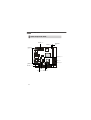
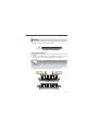
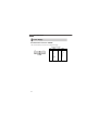
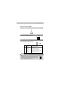
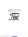
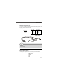
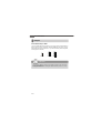
Fuzzy CN700G Series
MS-7199(V2.X) Mainboard
G52-71991X2
i
Copyright Notice
Th e material in this d ocument is the in tellectual p rop erty of MICRO-STAR
INTERNATIONAL. We take every care in the preparation of this document, but no
guarantee is given as to the correctness of its contents. Our products are under
continual improvement and we reserve the right to make changes without notice.
Trademarks
All trademarks are the properties of their respective owners.
NVIDIA, the NVIDIA logo, DualNet, and nForce are registered trademarks or trademarks of NVIDIA Corporation in the United States and/or other countries.
AMD, Athlon™, Athlon™ XP, Thoroughbred™, and Duron™ are registered trademarks of AMD Corporation.
Intel® and Pentium® are registered trademarks of Intel Corporation.
PS/2 and OS ®/2 are registered trademarks of International Business Machines
Corporation.
Windows® 95/98/2000/NT/XP are registered trademarks of Microsoft Corporation.
Netware® is a registered trademark of Novell, Inc.
Award® is a registered trademark of Phoenix Technologies Ltd.
AMI® is a registered trademark of American Megatrends Inc.
Revision History
Revision
V2.0
Revision History
First release
Date
June 2007
Technical Support
If a problem arises with your system and no solution can be obtained from the user’s
manual, please contact your place of purchase or local distributor. Alternatively,
please try the following help resources for further guidance.
Visit the MSI website for FAQ, technical guide, BIOS updates, driver updates,
an d oth er in forma tion : htt p:// glob al.m si.com.tw /ind ex.p hp?
func=faqIndex
Contact our technical staff at: http://support.msi.com.tw
ii
Safety Instructions
1.
Always read the safety instructions carefully.
2.
Keep this User’s Manual for future reference.
3.
4.
Keep this equipment away from humidity.
Lay this equipment on a reliable flat surface before setting it up.
5.
The openings on the enclosure are for air convection hence protects the equipment from overheating. DO NOT COVER THE OPENINGS.
6.
Make sure the voltage of the power source and adjust properly 110/220V before connecting the equipment to the power inlet.
7.
Place the power cord such a way that people can not step on it. Do not place
anything over the power cord.
8.
Always Unplug the Power Cord before inserting any add-on card or module.
9.
All cautions and warnings on the equipment should be noted.
10. Never pour any liquid into the opening that could damage or cause electrical
shock.
11. If any of the following situations arises, get the equipment checked by service
personnel:
† The power cord or plug is damaged.
† Liquid has penetrated into the equipment.
† The equipment has been exposed to moisture.
† The equipment does not work well or you can not get it work according to
User’s Manual.
† The equipment has dropped and damaged.
† The equipment has obvious sign of breakage.
12. DO NOT LEAVE THIS EQUIPMENT IN AN ENVIRONMENT UNCONDITIONED, STORAGE TEMPERATURE ABOVE 600 C (1400F), IT MAY DAMAGE THE EQUIPMENT.
CAUTION: Dan g er of exp losion if b attery is in correctl y rep laced .
Replace on ly with the same or equivalent type recommen ded by the
manufacturer.
iii
FCC-B Radio Frequency Interference Statement
This eq uip men t h as b een
tested and found to comply
with the limits for a Class B
digital device, pursuant to Part
15 of the FCC Rules. These limits are designed to provide reasonable protection
against harmful interference in a residential installation. This equipment generates,
uses and can radiate radio frequency energy and, if not installed and used in accordance with the instructions, may cause harmful interference to radio communications.
However, there is no guarantee that interference will not occur in a particular
installation. If this equipment does cause harmful interference to radio or television
reception, which can be determined by turning the equipment off and on, the user is
encouraged to try to correct the interference by one or more of the measures listed
bel ow.
† Reorient or relocate the receiving antenna.
† Increase the separation between the equipment and receiver.
† Connect the equipment into an outlet on a circuit different from that to
which the receiver is connected.
† Consult the dealer or an experienced radio/television technician for help.
Notice 1
The changes or modifications not expressly approved by the party responsible for
compliance could void the user’s authority to operate the equipment.
Notice 2
Shielded interface cables and A.C. power cord, if any, must be used in order to
comply with the emission limits.
VOIR LA NOTICE D’INSTALLATION AVANT DE RACCORDER AU RESEAU.
Micro-Star International
MS-7199
This device complies with Part 15 of the FCC Rules. Operation is subject to the
following two conditions:
(1) this device may not cause harmful interference, and
(2) this device must accept any interference received, including interference that
may cause undesired operation.
iv
WEEE (Waste Electrical and Electronic Equipment) Statement
v
vi
vii
CONTENTS
Copyright Notice ................................................................................................ ii
Tr ademar ks ........................................................................................................ ii
Revision History ................................................................................................ ii
Technical Support .............................................................................................. ii
Safety Instructions ........................................................................................... iii
FCC-B Radio Frequency Interference Statement ......................................... iv
WEEE (Waste Electrical and Electronic Equipment) Statement ..................... v
Chapter 1. Getting Started ............................................................................. 1-1
Mainboard Specifications ............................................................................. 1-2
Mainboard Layout ........................................................................................ 1-4
Packing Checklist ......................................................................................... 1-5
Chapter 2. Hardware Setup ............................................................................ 2-1
Quick Components Guide ............................................................................. 2-2
Memory ....................................................................................................... 2-3
Power Supply .............................................................................................. 2-4
Back Panel ................................................................................................... 2-5
Connectors .................................................................................................. 2-7
Jumpers ..................................................................................................... 2-12
Slots .......................................................................................................... 2-13
viii
Getting Started
Chapter 1
Getting Started
Thank you for choosing the Fuzzy CN700G Series
(MS-7199) V2.X Min i-ITX main board. The Fuzzy
CN700G Series mainboard is based on VIA® CN700
and VT8237R+ chipsets for optimal system efficiency.
The Fuzzy CN700G Series mainboard delivers a high
p erforman ce an d profession al desktop pl atform
solution.
1-1
MS-7199 Mainboard
Mainboard Specifications
Processor Support
-
VIA ® C7 1/ 1.5/ 2.0 GHz/ 21x21mm nano BGA2 package
TDP max 1GHz@9W/ 1.5GHz@12W/ 2.0GHz@20W
Supports VRM mobile (down to 0.7V)
Thermal design margin up to 100c Tcase
3D instructions SSE/ SSE2/ SSE3
Security Features RGN/ AES/ SHA-1
Supported FSB
- 400/ 800 MHz for 1.0/ 1.5/ 2.0 GHz
Chipset
- North Bridge: VIA ® CN700 chipset
- South Bridge: VIA ® VT8237R+ chipset
Memory Support
- Supports DDR2 400/ 533 SDRAM (non-ECC 533) (1GB Max)
- 1 DDR2 DIMM (240-pin/ 1.8V)
LAN
- Supports PCI LAN 1Gb Fast Ethernet by VIA ® RTL8110SC
Audio
- Chip integrated by VIA ® VT1618G
- Flexible 8-channel audio with jack sensing
- Compliant with AC97 2.3 spec
IDE
- 1 IDE port by VT8237R+
- Supports Ultra DMA 66/ 100/ 133 mode
- Supports PIO, Bus Master operation mode
SATA
- Supports two SATA ports by VT8237R+
- Supports storage and data transfers up to 150MB/s
RAID
- SATA1~2 supports RAID 0/ 1/ 0+1 or JBOD mode by VT8237R+
- Updated option ROM to support RAID
1-2
PDF created with pdfFactory Pro trial version www.pdffactory.com
Getting Started
Connectors
Back Panel
- 1 PS/2 mouse port
- 1 PS/2 keyboard port
- 2 serial ports (COMA and COMB)
- 2 USB 2.0 ports
- 1 LAN jack
- 3 flexible audio jacks
- 1 S-video port
- 1 DVI port
- 1 VGA port
On-Board Pinheaders
- 3 USB 2.0 pinheaders (6 ports)
- 1 audio pinheader
- 1 CD-In connector
- 1 Chassis Intrusion Switch pinheader
Slots
- 1 PCI slot
- Supports 3.3V/ 5V PCI bus Interface
Form Factor
- Mini-ITX (17 cm X 17 cm)
Mounting
- 4 mounting ho les
1-3
MS-7199 Mainboard
Mainboard Layout
ATXPWR
Top : mouse
Bottom:KB
VIA
C7
CPUFAN
Top : VGA Port
Bottom: DVI Port
VIA
CN700
DIMM1
VIA
VT1622A
Top: LAN Jack
Bottom: USB ports RTL8110SC
J5
Top : COMA
Bottom: COMB
JCI1
F_AUDIO
T:Line-In
M:Line-Out
B:Mic
CD_IN
J4
BIOS
VIA
VT1618
VIA
VT8237R Plus
J3
IDE1
S-Video Out VIA
VT1632A
JBAT1
SATA1 SATA2
BATT
+
J9
JFP2
PCI 1
Fuzzy CN700G Series
(MS-7199) V2.X Mini-ITX Mainboard
1-4
JFP1
Getting Started
Packing Checklist
MSI mainboard
Power Cable
MSI Driver/Utility CD
SATA Cable
Standard Cable for
IDE Devices
User’s Guide
* This picture is for reference only. Your packing contents may vary depending on the
model you purchased.
1-5
Hardware Setup
Chapter 2
Hardware Setup
This chapter provides you with the information about
hardware setup procedures. While doing the installation,
be careful in holding the components and follow the
installation procedures. For some components, if you
install in the wrong orientation, the components will not
work properly.
Use a grounded wrist strap before handling computer
comp onen ts. Static el ectricity may damag e th e
components.
2-1
MS-7199 Mainboard
Quick Components Guide
ATXPWR, p.2-4
CPUFAN, p.2-9
DDR2 DIMM,
p.2-3
Back Panel,
p.2-5
J3/J4/J5, p.2-11
IDE1, p.2-7
SATA1~2, p.2-8
F_AUDIO, p.2-9
PCI Slot, p.2-13
JFP2, p.2-10
JCI1, p.2-10
CD_IN, p.2-9
2-2
J9, p.2-11
JBAT1, p.2-12
JFP1, p.2-10
Hardware Setup
Memory
This DIMM slot is used for installing memory modules.
DDR2
240-pin, 1.8V
56x2=112 pin
64x2=128 pin
Installing Memory Modules
1. The memory module has only one notch on the center and will only fit in the right
orientation.
2. Insert the memory module vertically into the DIMM slot. Then push it in until the
golden finger on the memory module is deeply inserted in the DIMM slot.
Important
You can barely see the golden finger if the memory module is properly inserted
in the DIMM slot.
3. The plastic clip at each side of the DIMM slot will automatically close.
Volt
Notch
2-3
MS-7199 Mainboard
Power Supply
ATX 20-Pin Power Connector: ATXPWR
This connector allows you to connect to an ATX power supply.
ATXPWR Pin Definition
20
11
1
10
ATXPWR
2-4
PIN
SIGNAL
PIN
SIGNAL
1
2
3
4
5
6
7
8
9
3.3V
3.3V
GND
5V
GND
5V
GND
PW_OK
5V_SB
10
12V
11
12
13
14
15
16
17
18
19
20
3.3V
-12V
GND
PS_ON
GND
GND
GND
-5V
5V
5V
Hardware Setup
Back Panel
VGA Port
LAN
M ouse
L-In
S-Video
L-Out
Mic
Keyboard
DVI Port
USB Ports
Serial Ports
Mouse/Keyboard
The standard PS/2® mouse/keyboard DIN connector is for a PS/2® mouse/keyboard.
VGA Port
The DB15-pin female connector is provided for monitor.
DVI Port
The DVI (Digital Visual Interface) connector allows you to connect a LCD monitor. It
provides a high-speed digital interconnection between the computer and its display
device. To connect an LCD monitor, simply plug your monitor cable into the DVI
connector, and make sure that the other end of the cable is properly connected to
your monitor (refer to your monitor manual for more information.)
S-Video Connector
The S-Video connector allows users to connect display devices for component
video output.
S-Video (Super-Video, sometimes referred to as Y/C Video, or component video) is
a video signal transmission in which the luminance signal and the chrominance signal
are transmitted separately to achieve superior picture clarity. The luminance signal
(Y) carries brightness information, which defines the black and white portion, and
the chrominance signal (C) carries color information, which defines hue and saturation.
An S-Video connection brings better video quality than a composite/RCA connection.
USB Port
The USB (Universal Serial Bus) port is for attaching USB devices such as keyboard,
mouse, or other USB-compatible devices.
Serial Port
The serial port is a 16550A high speed communications port that sends/ receives 16
bytes FIFOs. You can attach a serial mouse or other serial devices directly to the
connector.
2-5
MS-7199 Mainboard
LAN
The standard RJ-45 LAN jack is for connection to the Local Area Network (LAN). You
can connect a network cable to it.
Activity Indicator
B Type
No
100M Cable
Plug-in
Transmission
Transition
No
1000M Cable
Plug-in
Transmission
Transition
Link Indicator
Left LED
Right LED
Green
Lighting
Green
Lighting
Green
Blinking
Green
Lighting
Green
Lighting
Yellow
Lighting
Green
Blinking
Yellow
Lighting
Audio Ports
These audio connectors are used for audio devices. You can differentiate the color
of the audio jacks for different audio sound effects.
Line-In (Blue) - Line In, is used for external CD player, tapeplayer or other
audio devices.
Line-Out (Green) - Line Out, is a connector for speakers or headphones.
Mic (Pink) - Mic, is a connector for microphones.
2-6
Hardware Setup
Connectors
IDE Connector: IDE1
This connector supports IDE hard disk drives, optical disk drives and other IDE devices.
IDE1
Important
If you install two IDE devices on the same cable, you must configure the
drives separately to master / slave mode by setting jumpers. Refer to IDE
devi ce’s documentation suppl i ed by the vendors for jumper setting
instructions.
2-7
MS-7199 Mainboard
Serial ATA Connector: SATA1~SATA2
These connectors are high-speed Serial ATA interface ports. Each connector can
connect to one Serial ATA device.
7
7
1
1
SATA1 SATA2
Important
Please do not fold the Serial ATA cable into 90-degree angle. Otherwise,
data loss may occur during transmission.
2-8
Hardware Setup
Fan Power Connector: CPUFAN
GND
POWER_OUT
+1 2V
The fan power connector supports system cooling fan with +12V. When connecting
the wire to the connector, always note that the red wire is the positive and should be
connected to the +12V, the black wire is Ground and should be connected to GND.
CPUFAN
CD-In Connector: CD_IN
CD_IN
This connector is provided for CD-ROM audio.
R
GND
L
Front Panel Audio Connector: F_AUDIO
This connector allows you to connect the front panel audio and is compliant with
Intel® Front Panel I/O Connectivity Design Guide.
10
9
2
1
F_AUDIO
Pin Definition
PIN
SIGNAL
DESCRIPTION
1
2
3
4
5
6
7
8
9
10
AUD_MIC
AUD_GND
AUD_MIC_BIAS
AUD_VCC
AUD_FPOUT_R
AUD_RET_R
HP_ON
KEY
AUD_FPOUT_L
AUD_RET_L
Front panel microphone input signal
Ground used by analog audio circuits
Microphone power
Filtered +5V used by analog audio circuits
Right channel audio signal to front panel
Right channel audio signal return from front panel
Reserved for future use to control headphone amplifier
No pin
Left channel audio signal to front panel
Left channel audio signal return from front panel
Important
If you don’t want to connect to the front audio header, pins 5 &
6, 9 & 10 have to be jumpered in order to have signal output
directed to the rear audio ports. Otherwise, the Line-Out connector on the back panel will not function.
10
9
6
5
2-9
MS-7199 Mainboard
Front Panel Connectors: JFP1, JFP2
These connectors are for electrical connection to the front panel switches and LEDs.
The JFP1 is compliant with Intel® Front Panel I/O Connectivity Design Guide.
JFP1 Pin Definition
Reset HDD
Switch LED
JFP1
9
10
1
2
Power
Switch
Power
LED
PIN
SIGNAL
DESCRIPTION
1
2
3
4
5
6
7
8
9
HD_LED_P
FP PWR/SLP
HD_LED_N
FP PWR/SLP
RST_SW_N
PWR_SW_P
RST_SW_P
PWR_SW_N
RSVD_DNU
Hard disk LED pull-up
MSG LED pull-up
Hard disk active LED
MSG LED pull-up
Reset Switch low reference pull-down to GND
Power Switch high reference pull-up
Reset Switch high reference pull-up
Power Switch low reference pull-down to GND
Reserved. Do not use.
JFP2 Pin Definition
Speaker
+
+ -
JFP2
2
1
8
7
Power
LED
PIN
SIGNAL
PIN
SIGNAL
1
GND
2
SPK-
3
5
7
PLED2
PLED1
CUT
4
6
8
BUZ+
BUZSPK+
Chassis Intrusion Connector: JCI1
This connector connects to the chassis intrusion switch cable. If the chassis is
opened, the chassis intrusion mechanism will be activated. The system will record
this status and show a warning message on the screen. To clear the warning, you
must enter the BIOS utility and clear the record.
JCI1
1
2
CINTRU
GND
2-10
PDF created with pdfFactory Pro trial version www.pdffactory.com
Hardware Setup
Front USB Connector: J3,J4,J5
This connector, compliant with Intel® I/O Connectivity Design Guide, is ideal for connecting high-speed USB interface peripherals such as USB HDD, digital cameras,
MP3 players, printers, modems and the like.
Pin Definition
9
10
1
2
J3/J4/J5
(USB 2.0)
PIN
SIGNAL
PIN
SIGNAL
1
VCC
2
VCC
3
USB0-
4
USB1-
5
USB0+
6
USB1+
7
GND
8
GND
9
Key (no pin)
10
USBOC
USB 2.0 Bracket
(Optional)
Important
Note that the pins of VCC and GND must be connected correctly to avoid
possible damage.
Wake On LAN Connector: J9
This connector allows you to connect to a LAN card with Wake On LAN function. You
can wake up the computer via remote control through a local area network.
J9
MP_WAKEUP
GND
1
5VSB
2-11
MS-7199 Mainboard
Jumpers
Clear CMOS Jumper: JBAT1
There is a CMOS RAM onboard that has a power supply from an external battery to
keep the data of system configuration. With the CMOS RAM, the system can automatically boot OS every time it is turned on. If you want to clear the system configuration,
set the jumper to clear data.
1
1
1
3
3
JBAT1
Keep Data
Clear Data
Important
You can clear CMOS by shorting 2-3 pin while the system is off. Then return
to 1-2 pin position. Avoid clearing the CMOS while the system is on; it will
damage the mainboard.
2-12
Hardware Setup
Slot
PCI (Peripheral Component Interconnect) Slot
The PCI slot supports LAN card, SCSI card, USB card, and other add-on cards that
comply with PCI specifications.
PCI Slot
PCI Interrupt Request Routing
The IRQ, acronym of interrupt request line and pronounced I-R-Q, are hardware lines
over which devices can send interrupt signals to the microprocessor. The PCI IRQ
pins are typically connected to the PCI bus pins as follows:
PCI Slot 1
Order 1
Order 2
Order 3
Order 4
INT B#
INT C#
INT D#
INT A#
2-13