1
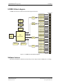
® Digital I/O UCERB 24 USB Electromechanical Relay Module - 24 SPDT (Form C) Relays, with 24 Screw Terminals USER’S MANUAL VER. 4 • MAY 2005 No part of this manual may be reproduced without permission ® CyberResearch , Inc. www.cyberresearch.com 25 Business Park Dr., Branford, CT 06405 USA 203-483-8815 (9am to 5pm EST) FAX: 203-483-9024 ® CyberResearch Digital I/O UCERB 24 ©Copyright 2005 All Rights Reserved. May 1, 2005 The information in this document is subject to change without prior notice in order to improve reliability, design, and function and does not represent a commitment on the part of CyberResearch, Inc. In no event will CyberResearch, Inc. be liable for direct, indirect, special, incidental, or consequential damages arising out of the use of or inability to use the product or documentation, even if advised of the possibility of such damages. This document contains proprietary information protected by copyright. All rights are reserved. No part of this manual may be reproduced by any mechanical, electronic, or other means in any form without prior written permission of CyberResearch, Inc. Trademarks “CyberResearch,” and “UCERB 24,” are trademarks of CyberResearch, Inc. Other product names mentioned herein are used for identification purposes only and may be trademarks and/or registered trademarks of their respective companies. • NOTICE • CyberResearch, Inc. does not authorize any CyberResearch product for use in life support systems, medical equipment, and/or medical devices without the written approval of the President of CyberResearch, Inc. Life support devices and systems are devices or systems which are intended for surgical implantation into the body, or to support or sustain life and whose failure to perform can be reasonably expected to result in injury. Other medical equipment includes devices used for monitoring, data acquisition, modification, or notification purposes in relation to life support, life sustaining, or vital statistic recording. CyberResearch products are not designed with the components required, are not subject to the testing required, and are not submitted to the certification required to ensure a level of reliability appropriate for the treatment and diagnosis of humans. CyberResearch, Inc. 25 Business Park Drive Branford, CT USA iii P: (203) 483-8815; F: (203) 483-9024 www.cyberresearch.com ® CyberResearch Digital I/O UCERB 24 Intentionally Blank iv ©Copyright 2005 CyberResearch, Inc. ® CyberResearch Digital I/O UCERB 24 Preface About this User’s Guide..........................................................................................1 What you will learn from this user’s guide..........................................................................1 Conventions in this user’s guide ..........................................................................................1 Chapter 1 Introducing the UCERB 24......................................................................................2 Overview: UCERB 24 features................................................................................2 USB-ERB24 block diagram.....................................................................................3 Software features .....................................................................................................3 Connecting a USB-ERB24 to your computer is easy ..............................................4 Chapter 2 Installing the USB ERB24 .......................................................................................5 What comes with your USB-ERB24 shipment?......................................................5 Hardware..................................................................................................................5 Software ...................................................................................................................5 Unpacking the UCERB 24.......................................................................................6 Installing the UCERB 24 .........................................................................................6 Configuring the hardware switches ........................................................................6 Connecting the external power supply ....................................................................7 Connecting the UCERB 24 to your system ............................................................8 Installing the software..............................................................................................9 Chapter 3 Functional Details ..................................................................................................14 Internal components...............................................................................................14 USB in connector...................................................................................................14 USB out connector.................................................................................................14 External power connectors.....................................................................................14 USB LED ...............................................................................................................15 PWR LED ..............................................................................................................15 Invert/non-invert switch (S1).................................................................................15 Pull-up/pull-down switch (S2)...............................................................................16 Screw terminals......................................................................................................16 Daisy chaining additional relays to the UCERB 24...............................................16 Power limitations using multiple UCERB 24 Devices ..........................................17 Voltage drop...........................................................................................................17 Relay configuration................................................................................................17 Relay contact protection circuit for inductive loads ..............................................18 Chapter 4 Specifications.........................................................................................................19 Output specifications .............................................................................................19 Power .....................................................................................................................20 External power input..............................................................................................20 External power output............................................................................................20 USB specifications.................................................................................................21 Relay contact pull-up/down option........................................................................21 Mechanical.............................................................................................................21 Environmental........................................................................................................21 CyberResearch, Inc. 25 Business Park Drive Branford, CT USA v P: (203) 483-8815; F: (203) 483-9024 www.cyberresearch.com UCERB 24 vi ® CyberResearch Digital I/O ©Copyright 2005 CyberResearch, Inc. ® CyberResearch Digital I/O UCERB 24 Preface About this User’s Guide What you will learn from this user’s guide This user’s guide explains how to install, configure, and use the UCERB 24 so that you get the most out of its electromechanical relay features. This user's guide also refers you to related documents available on our web site, and to technical support resources. Conventions in this user’s guide For more information on … Text presented in a box signifies additional information and helpful hints related to the subject matter you are reading. Caution! Shaded caution statements present information to help you avoid injuring yourself and others, damaging your hardware, or losing your data. <#:#> Angle brackets that enclose numbers separated by a colon signify a range of numbers, such as those assigned to registers, bit settings, etc. bold text Bold indicates names of objects on the screen, such as buttons, text boxes, and check boxes. For example: 1. Insert the disk or CD and click the OK button. italic text Italic text indicates the names of manuals and help topic titles, and to emphasize a word or phrase. For example: Never touch the exposed pins or circuit connections on the board. CyberResearch, Inc. 25 Business Park Drive Branford, CT USA 1 P: (203) 483-8815; F: (203) 483-9024 www.cyberresearch.com UCERB 24 ® CyberResearch Digital I/O Chapter 1 Introducing the UCERB 24 Overview: UCERB 24 features This user's guide contains all of the information you need to connect the UCERB 24 to your computer and to the external devices you want to control. You can use the UCERB 24 in your control applications to switch on and off a variety of devices, such as fans, blowers, pumps, etc. The UCERB 24 is a USB 2.0 full-speed, electromechanical relay module. It is supported under Microsoft® Windows® 98 (2nd edition), Windows ME, Windows 2000, and Windows XP. The UCERB 24 has 24 single-pole double-throw (SPDT) Form C electromechanical relays. The digital I/O lines on your USB module directly control the relays on your UCERB 24. You connect your field wiring directly to the board's screw terminals. The screw terminals provide three connections to each relay – normally open (NO), normally closed (NC), and common (C). You can configure the logic polarity and power-on state of each bank of relays with on-board switches. The relays are configurable as two banks of eight and two banks of four. Switch settings can be read back with software. The UCERB 24 is powered by an external 9 V, 3 A regulated power supply that is shipped with the device. A USB cable is also included. Power OUT and USB OUT connectors let you power and control multiple boards from one external power source and one USB port in a daisy chain fashion. Depending on your load requirement, daisy chained boards may require a separate power supply. The UCERB 24 is shipped in a rugged enclosure that you can mount on a DIN rail or on a bench. 2 ©Copyright 2005 CyberResearch, Inc. ® CyberResearch Digital I/O UCERB 24 UCERB 24 block diagram UCERB 24 functions are illustrated in the block diagram shown here. Relay 13 Relay 12 500 mA USB 2.0 compliant interface USB Microcontroller Relay 11 Relay driver 8 Relay 10 Relay 9 Relay 8 Relay 7 Switch S1 (inv/non-inv) Switch S2 (pull-up/down) Relay 6 Relay driver 8 Relay 5 Relay 4 Relay 3 Relay 2 Relay 1 24 23 22 21 20 19 18 17 16 15 14 Relay 14 13 Relay 15 12 Relay 16 Power Regulator 11 Relay 17 10 Relay 18 9 Relay 19 8 4 7 Relay driver 6 Relay 20 5 Power Monitor Relay 21 4 9.0 V External Power Relay 22 3 4 2 Relay 23 Relay driver 1 Relay 24 NC C NO NC C NO NC C NO NC C NO NC C NO NC C NO NC C NO NC C NO NC C NO NC C NO NC C NO NC C NO NC C NO NC C NO NC C NO NC C NO NC C NO NC C NO NC C NO NC C NO NC C NO NC C NO NC C NO NC C NO Screw terminal Figure 1-1. UCERB 24 functional block diagram Software features The InstaCal installation, calibration, and test utility software ships with the UCERB 24 free of charge. CyberResearch, Inc. 25 Business Park Drive Branford, CT USA 3 P: (203) 483-8815; F: (203) 483-9024 www.cyberresearch.com UCERB 24 ® CyberResearch Digital I/O Connecting a UCERB 24 to your computer is easy Installing a data acquisition device has never been easier. 4 The UCERB 24 relies upon the Microsoft Human Interface Device (HID) class drivers. The HID class drivers ship with every copy of Windows that is designed to work with USB ports. We use the Microsoft HID because it is a standard, and its performance delivers full control and maximizes data transfer rates for your UCERB 24. No third-party device driver is required. You can connect the UCERB 24 before or after you install the software, and without powering down your computer first. When you connect an HID to your system, your computer automatically detects it and configures the necessary software. You can connect multiple HID peripherals to your system using a USB hub. You can connect your system to various devices using a standard four-wire cable. The USB connector replaces the serial and parallel port connectors with one standardized plug and port combination. Data can flow two ways between a computer and peripheral over USB connections. ©Copyright 2005 CyberResearch, Inc. ® CyberResearch Digital I/O UCERB 24 Chapter 2 Installing the UCERB 24 What comes with your UCERB 24 shipment? The following items are shipped with the UCERB 24. Hardware The following items should be included with your shipment. UCERB 24 External power supply and cord – 9 volt, 3 amp DC power supply USB cable (2 meter length) Software The CyberResearch Software CD contains the : InstaCal installation, calibration, and test utility Universal Driver Library Universal LabView Drivers CyberResearch, Inc. 25 Business Park Drive Branford, CT USA 5 P: (203) 483-8815; F: (203) 483-9024 www.cyberresearch.com ® CyberResearch Digital I/O UCERB 24 Unpacking the UCERB 24 As with any electronic device, you should take care while handling to avoid damage from static electricity. Before removing the UCERB 24 from its packaging, ground yourself using a wrist strap or by simply touching the computer chassis or other grounded object to eliminate any stored static charge. If your UCERB 24 is damaged, notify CyberResearch, Inc. immediately by phone, fax, or e-mail. Phone: 203.483.8815. Fax: 203.483.9024 to the attention of Tech Support Email: [email protected] Installing the UCERB 24 The UCERB 24 has two on-board switches that you set to configure the relay logic polarity and the resistor pull-up/down configuration. Configure these switches before you connect the external power . supply to the UCERB 24. Factory-configured default settings are listed in Table 2-1. Refer to Figure 3.1 for the location of each switch on the UCERB 24. Configuring the hardware switches The UCERB 24 has two on-board switches that you set to configure the relay control logic polarity and the relay power-on state. Factory-configured default settings are listed in Table 2.1 Refer to Figure 3.1 for the location of each switch on the UCERB 24. Table 2-1. Default switch configuration 6 Board label Description Default setting INVERT NON-INVERT S1 Pull DOWN PULL UP S2 Configures the relay control logic parity per relay bank for invert or non-invert logic. Non-invert Configures the relay power-on state per relay bank for pull-up or pull-down. Pull-down ©Copyright 2005 CyberResearch, Inc. ® CyberResearch Digital I/O UCERB 24 Each DIP switch sets the configuration of one relay group. The DIP switch labeled A configures relays 1 to 8, the switch labeled B configures relays 9 to 16, the switch labeled CL configures relays 17 to 20, and the switch labeled CH configures relays 21 to 24 (Figure 2-2). A B CL CH Configures relays 9-16 Configures relays17-20 Configures relays21-24 Figure 2-2. Typical board switch Port A consists of relays 1 through 8, Port B consists of relays 9 through 16, Port CL consists of relays 17 through 20, and Port CH consists of relays 21 through 24. Remove from the enclosure to access the on-board switches To change the configuration of a switch, you must first remove the UCERB 24 from the enclosure. Relay control logic polarity Configure the Invert/non-invert switch (S1) to set the relay control logic polarity for each relay bank for invert or non-invert. By default, this switch is shipped with all banks configured for non-inverted logic, as shown in Figure 2-3. INVERT NON-INVERT A B CL CH S1 Figure 2-3. Relay logic switch S1 NON-INVERT mode: when "0" is written or read back via the USB bus, the relays are not energized. INVERT mode: when "0" is written or read back via the USB bus, the relays are energized. Switch settings for polarity can be read back via software through the USB bus. Switch settings for S1 do not affect the power-on condition. Relay power-on state Configure the Pull-up/pull-down switch (S2) to set the state of each relay bank at power-up. By default, this product is shipped with the switch for all banks configured for pull-down (relays inactive at power up), as shown in Figure 2-4. Switch settings can be read back via software through the USB bus. PULL DOWN S2 PULL UP A B CL CH Figure 2-4. Resistor pull-up/down switch S2 PULL-UP: the relays are put into an energized state at power-up, regardless of the state of switch S1 PULL-DOWN: the relays are put into a non-energized state at power-up. Connecting the external power supply Power to the UCERB 24 is provided with the 9 V, 3 A external power supply. You must connect the the external power supply before connecting the USB connector to the UCERB 24. To connect the power supply to your UCERB 24, do the following: 1. Connect the external power cord to the power connector labeled POWER IN on the UCERB 24 enclosure (PWR IN on the board). Refer to Figure 3-1 for the location of this connector. 2. Plug the AC adapter into a power outlet. CyberResearch, Inc. 25 Business Park Drive Branford, CT USA 7 P: (203) 483-8815; F: (203) 483-9024 www.cyberresearch.com UCERB 24 ® CyberResearch Digital I/O The PWR LED illuminates green when 9 V power is supplied to the UCERB 24. If the voltage supply is less than 6.0 V or more than 12.5 V, the PWR LED does not light. Do not connect external power to the POWER OUT connector The power connector labeled POWER OUT on the enclosure (PWR OUT on the board) is used to provide power to an additional products. If you connect the external power supply to the POWER OUT connector, the UCERB 24 does not receive power, and the PWR LED will not illuminate. Connecting the UCERB 24 to your system To connect the UCERB 24 to your system, turn your computer on, and connect the USB cable to a USB port on your computer or to an external USB hub that is connected to your computer. The USB cable provides communication to the UCERB 24. When you connect the UCERB 24 for the first time, a Found New Hardware popup balloon (Windows XP) or dialog (other Windows versions) opens as the UCERB 24 is detected. When this balloon or dialog closes, the installation is complete. The USB LED should flash and then remain lit. This indicates that communication is established between the UCERB 24 and your computer. If you are running Windows XP and connect the UCERB 24 to a USB 1.1 port, a balloon displays the message "Your USB device can perform faster if you connect to a USB 2.0 port." You can ignore this message. The UCERB 24 will function properly when connected to a USB 1.1 port. Caution! Do not disconnect any device from the USB bus while the computer is communicating with the UCERB 24, or you may lose data and/or your ability to communicate with the UCERB 24. If the LED turns off If the LED is lit but then turns off, the computer has lost communication with the UCERB 24. To restore communication, disconnect the USB cable from the computer, and then reconnect it. This should restore communication, and the LED should turn back on. 8 ©Copyright 2005 CyberResearch, Inc. ® CyberResearch Digital I/O UCERB 24 Installing the software Turn your computer on if it is not already running. Log onto Windows with administrative privileges. Make sure you are using the latest system software. Download and install the latest Microsoft Windows updates Make sure you have XP Hotfix KB822603 installed. This update is intended to address a serious error in Usbport.sys when you operate a USB device. Run Windows Update or download the update from www.microsoft.com/downloads/details.aspx?familyid=733dd867-56a0-4956-b7fee85b688b7f86&displaylang=en. For more information, refer to the Microsoft Knowledge Base article "Availability of the Windows XP SP1 USB 1.1 and 2.0 update." This article is available at support.microsoft.com/?kbid=822603. 1. Close all applications you have running, including anti-virus software. 2. Insert the CyberResearch Software CD into your CD drive and let autorun. Choose whether or not to install the .NET Framework 1.1 If the .NET Framework 1.1 is already installed on your computer, proceed to the Install the DAQ Software section. If the .NET Framework 1.1 is not installed on your computer, the following DAQ install information dialog opens. CyberResearch, Inc. 25 Business Park Drive Branford, CT USA 9 P: (203) 483-8815; F: (203) 483-9024 www.cyberresearch.com ® CyberResearch Digital I/O UCERB 24 1. Click on the OK button. The Microsoft .NET Framework 1.1 Setup dialog opens. 2. The button you click depends on whether or not you want to install the .NET Framework 1.1 on your computer. To install the .NET Framework 1.1, click on the Yes button. To bypass installing the .NET Framework 1.1, click on the No button. We strongly recommend that you install the Microsoft .NET Framework 1.1 The DAQ software installer program and some DAQ software components require that the .NET Framework 1.1 package be installed. If you do not install the .NET Framework 1.1, you may not be able to properly install the DAQ software. 10 ©Copyright 2005 CyberResearch, Inc. ® CyberResearch Digital I/O UCERB 24 Install the DAQ Software Whether or not you install the.NET Framework 1.1, the remaining dialogs are the same, starting with the Welcome… dialog. 1. Click on the Next > button. 2. The Installation Information dialog opens. 3. Read the information on this dialog. If a warning dialog opens during this installation asking to allow scripts to run, click the appropriate option that allows them to run. 4. Click on the Next > button. CyberResearch, Inc. 25 Business Park Drive Branford, CT USA 11 P: (203) 483-8815; F: (203) 483-9024 www.cyberresearch.com ® CyberResearch Digital I/O UCERB 24 5. Read the license agreement. If you agree with the terms, click on the I accept the terms of this license agreement option, and then click on the Next > button. The Ready to install the programs dialog opens. 6. Click on the Install button. The Installing DAQ Software dialog opens, and stays open while the software installs. 12 ©Copyright 2005 CyberResearch, Inc. ® CyberResearch Digital I/O UCERB 24 When the software is installed, the Setup Completed dialog opens. If VS .NET is not detected during installation If Visual Studio .NET is not detected, the Setup Completed dialog instructs you to install VS .NET. Restart your computer Installing UL or UL for LabVIEW? If you are going to install the Universal Library or Universal Library for LabVIEW, you can install either of the packages before you restart. Unpack and install your USB device after your computer restarts. CyberResearch, Inc. 25 Business Park Drive Branford, CT USA 13 P: (203) 483-8815; F: (203) 483-9024 www.cyberresearch.com ® CyberResearch Digital I/O UCERB 24 Chapter 3 Functional Details Internal components The UCERB 24 has the following internal components, as shown in Figure 3-1. Two (2) USB connectors Two (2) external power connectors USB LED PWR LED Invert/non-invert switch (S1) — sets the relay control logic polarity Pull-up/down switch (S2) — sets the relay power-on state Screw terminals USB IN POWER IN USB OUT POWER OUT Invert/non-invert switch (S1) Pull-up/pull-down switch (S2) PWR LED USB LED Screw terminals Figure 3-1. UCERB 24 components USB in connector The USB out connector is labeled USB IN on the board and enclosure. The USB IN connector is a USB 2.0 full-speed input connector that you connect to the USB port on your computer (or USB hub connected to your computer). This connector supports USB 1.1, USB 2.0 devices. USB out connector The USB out connector is labeled USB OUT on the board and enclosure. The USB OUT connector is a downstream hub output port intended for use with other CyberResearch products only. The USB hub is self-powered, and can provide 100 mA maximum current at 5 V. For information on daisy chaining to other CyberResearch products, refer to Daisy chaining additional modules to the USB-ERB08. External power connectors The UCERB 24 has two external power connectors labeled POWER IN and POWER OUT on the enclosure. The POWER IN connector is labeled PWR IN and P19 on the board, and the POWER OUT connector is labeled PWR OUT and P20 on the board. Connect the POWER IN connector to the supplied +9 V external power supply. External power is required to operate the UCERB 24. The POWER OUT connector lets you power additional daisy chained products from a single external power supply. Depending on your load requirements, daisy chained products may require a separate power supply. Refer to "Power limitations using multiple UCERB 24 devices" for more information. 14 ©Copyright 2005 CyberResearch, Inc. ® CyberResearch Digital I/O UCERB 24 USB LED The USB LED indicates the communication status of the UCERB 24. It uses up to 5 mA of current and cannot be disabled. Table 3-2 explains the USB LED function. Table 3-2. USB LED Illumination USB LED illumination Indication Steady green Pulsing green The UCERB 24 is connected to a computer or external USB hub. Initial communication is established between the UCERB 24 and the computer, or data is being transferred. PWR LED The UCERB 24 incorporates an on-board voltage supervisory circuit that monitors the external 9 V power. If the input voltage falls outside of the specified range, the PWR LED shuts off. Table 3-3 explains the function of the PWR LED. Table 3-3. PWR LED Illumination PWR LED illumination Indication Steady green Off External power is supplied to the UCERB 24. Power is not supplied by the external supply, or a power fault has occurred. A power fault occurs when the input power falls outside of the specified voltage range of the external supply (6.0 V to 12.5 V). Invert/non-invert switch (S1) The Invert/non-invert switch (S1) sets the relay control logic per relay bank to either inverted or noninverted. By default, switch S1 is configured for non-invert (see Figure 3-2). INVERT S1 NON-INVERT A B CL CH Figure 3-2. Switch S1 default configuration The switch labeled A configures relays 1 through 8, the switch labeled B configures relays 9 through 16, the switch labeled CH configures relays 17 through 20, the switch labeled CL configures relays 21 through 24. NON-INVERT: when "0" is written or read back via the USB bus, the relays are not energized. INVERT: when "0" is written or read back via the USB bus, the relays are energized. Switch settings do not affect the power-on condition. Use InstaCal to read the current logic setting for each module group. CyberResearch, Inc. 25 Business Park Drive Branford, CT USA 15 P: (203) 483-8815; F: (203) 483-9024 www.cyberresearch.com ® CyberResearch Digital I/O UCERB 24 Pull-up/pull-down switch (S2) The Pull-up/pull-down switch (S2) sets the power-on state of each relay bank. By default, switch S2 is configured for pull-down (relays inactive at power-up – see Figure 3-3). PULL DOWN PULL UP S2 A B CL CH Figure 3-3. Switch S2 default configuration The switch labeled A configures relays 1 through 8, the switch labeled B configures relays 9 through 16, the switch labeled CH configures relays 17 through 20, the switch labeled CL configures relays 21 through 24. PULL UP: the relay energizes at power-up, regardless of the state of switch S1. PULL DOWN: the relays are not energized at power-up. Use InstaCal to read the current power-on state setting for each module group. Screw terminals Connect external devices to the relay contacts using the UCERB 24 board's 24 sets of screw terminals. Each relay has a normally closed (NC), common (C), and normally open (NO) contact. Figure 3-4 shows the screw terminals on a typical relay channel. NC C NO Figure 3-4. Typical relay channel Each screw terminal is identified with a label on the board and on the underside of the enclosure lid. Caution! Before connecting wires to the screw terminals, turn off the power to the UCERB 24, and make sure that the signal wires do not contain live voltages. Use 12-22 AWG wire for your signal connections. Properly insulate the wires to avoid any short circuit to the other channels, ground, or other points on the board. Caution! Keep the length of stripped wire at a minimum to avoid a short to the enclosure! When connecting your field wiring to the screw terminals, use the strip gage on the terminal strip, or strip to 5.5 - 7.0 mm (0.215" to 0.275") long. Daisy chaining additional relays to the UCERB 24 Daisy chained CyberResearch products connect to the USB bus through the high-speed hub on the UCERB 24. You can daisy chain a maximum of four CyberResearch products to a single USB 2.0 port or USB 1.1 port on your computer. Other CyberResearch products are USB 1.1 full-speed devices that provide a signaling bit rate of 12 Mb/s. The throughput rate is shared by all devices connected to the USB bus. Use the supplied cable or an equivalent cable when daisy chaining CyberResearch products. Use full-speed cables for daisy chaining to additional products. To daisy chain two or more UCERB 24 relay boards, follow the steps below. This procedure assumes you already have one UCERB 24 connected to a computer and to an external power source. The UCERB 24 already connected to the computer is referred to as the connected module. The UCERB 24 you want to daisy chain to the connected board is referred to as the new module. 16 ©Copyright 2005 CyberResearch, Inc. ® CyberResearch Digital I/O 1. UCERB 24 Connect the POWER OUT connector on the connected module to the POWER IN connector on the new module. This step is required only if you plan to daisy chain power to another module. 2. Connect the USB OUT connector on the connected module to the USB IN connector on the new module. 3. To add another module, repeat steps 1-2, with the module you just connected now being the connected module. A daisy chain example is shown in Figure 3-5. Note that the last board in the chain is supplied with external power. USB port to USB IN POWER OUT to POWER IN USB OUT to USB IN USB OUT to USB IN UCERB 24 power supply to POWER IN CB -PWR -9V3A supply to POWER IN Figure 3-5. Daisy chain connections Power limitations using multiple UCERB 24 devices When daisy chaining additional CyberResearch products to the UCERB 24, you must ensure that you provide adequate power to each board that you connect. The UCERB 24 is powered with a 9 VDC nominal, 3.0 A external power supply. Voltage drop A drop in voltage occurs with each board connected in a daisy chain system. The voltage drop between the power supply input and the daisy chain output is 0.5 V maximum. Factor in this voltage drop when you configure a daisy chain system to ensure that at least 6.0 VDC is provided to the last board in the chain. Relay configuration You can install a pull-up or pull-down resistor at the NO and NC terminals on each relay. Note that the pull-up resistors are tied to the 5 V power and should be considered when calculating the power budget. The relay configuration is illustrated in the following schematic User-installed pull-up / pull-down resistor +5 GND +5 GND Buffer/ driver Digital output from the user C NO NC 10 k resistor Screw terminals (3 per relay) Pull-up/pull-down switch S2 Figure 3-6. Relay configuration CyberResearch, Inc. 25 Business Park Drive Branford, CT USA 17 P: (203) 483-8815; F: (203) 483-9024 www.cyberresearch.com ® CyberResearch Digital I/O UCERB 24 The relay contacts associated that are with each relay location are listed in Table 3-4. Table 3-4. Relay locations and associated contacts R35, R36, R41, R43, R45, R47, R49, R51, R87, R89, R91, R93, R96, R98, R100, R102, R103, R105, R107, R109, R112, R114, R116, R118 R37, R40, R42,R44, R46, R48, R50, R52, R88, R90, R92, R94, R95, R97, R99, R101, R104, R106, R108, R110, R111, R113, R115, R117 Relays NO contact pull-up (to USB +5 V) / pull-down, user installed. Relays NC contact pull-up (to USB +5 V) / pull-down, user installed Relay contact protection circuit for inductive loads When you connect an inductive load to a relay, energy stored in the inductive load can induce a large voltage surge when you switch the relay. This voltage can severely damage the relay contacts. To limit the voltage surge across the inductive load in a DC circuit, install a kickback diode across the inductive load. Refer to the contact protection circuit in Figure 3-7. For AC loads, install a metal oxide varistor (MOV). Relay NO C NC + V - Inductive Load Kickback Diode Figure 3-7. Relay contact protection circuit 18 ©Copyright 2005 CyberResearch, Inc. ® CyberResearch Digital I/O UCERB 24 Chapter 4 Specifications Typical for 25 °C unless otherwise specified. Specifications in italic text are guaranteed by design. Output specifications Table 4-1. Output specifications Number of relays Relay configuration Contact configuration Contact rating Contact resistance Operate time Release time Vibration Shock Dielectric isolation (between relay open contact) Dielectric isolation (between PCB output lines) Life expectancy Power on S2 = state pull-up S2 = pulldown Relay control logic polarity Pull-up / pull-down CyberResearch, Inc. 25 Business Park Drive Branford, CT USA 24 2 banks of 8 and 2 banks of 4 24 Form C (SPDT) Normally Open, Normally Closed and Common available at screw terminals 6 A @ 240 VAC or 28 VDC resistive 100 milliohms max (initial value) 10 milliseconds max 5 milliseconds max 10 to 55 Hz (amplitude 1.5 mm) 10 G (11 milliseconds) 300 VAC, 50/60 Hz (1 minute) 500VAC, 50/60 Hz (1 minute) 10 million mechanical operations, min Energized. NO in contact with Common Not energized. NC in contact to Common User-configurable per bank via switch S1 for invert or non-invert (default). Switch settings for polarity can be read back via software through the USB bus. Switch settings do not affect the power on condition. Non-invert mode, when "0" is written or read back via the USB bus, relays are not energized. Invert mode, when "0" is written or read back via the USB bus, relays are energized. User-configurable per bank via switch S2 for pull-down (default) or pull-up. Switch Settings can be read back via software. Pull-down will put the relays in non-energized mode on power up. Pull-up will put the relays in energized mode on power up. 19 P: (203) 483-8815; F: (203) 483-9024 www.cyberresearch.com ® CyberResearch Digital I/O UCERB 24 Power Table 4-2. Power specifications Parameter Conditions Specification USB +5 V input voltage range USB +5 V supply current External power supply (required) Voltage supervisor limits - PWR LED All modes of operation Vext < 6.0 V, Vext > 12.5 V 6.0 V < Vext < 12.5 V All relays on, 100 mA downstream hub power All relays off, 100 mA downstream hub power External power consumption 4.75 V min. to 5.25 V max. 10 mA max 9 V ±10% @ 3 A PWR LED = Off (power fault) PWR LED = On 1.5 A typ, 1.8 A max 230 mA typ, 270 mA max External power input Table 4-3. External power input specifications Parameter Conditions External power input Voltage supervisor limits - PWR LED (Note 1) 6.0 V > Vext or Vext > 12.5 V 6.0 V < Vext < 12.5 V External power adapter (included) Note 1: Specification +6.0 VDC to 12.5 VDC (9 VDC power supply included). PWR LED = Off (power fault) PWR LED = On +9 V ±10%, @ 3 A The UCERB 24 monitors the external +9 V power supply voltage with a voltage supervisory circuit. If this power supply exceeds its specified limit, the PWR LED will turn off indicating a power fault condition. External power output Table 4-4. External power output specifications Parameter External power output - current range External power output (Note 2) Compatible cable(s) for daisy chain Conditions Specification 4.0 A max. Voltage drop between power input and daisy chain power output C-MAPWR-x 0.5 V max x = 2 , 3 or 6 feet The daisy chain power output option allows multiple boards to be powered from a single external power source in a daisy chain fashion. The voltage drop between the module power supply input and the daisy chain output is 0.5 V max. Users must plan for this drop to ensure the last module in the chain will receive at least 6.0 VDC. Note 2: 20 ©Copyright 2005 CyberResearch, Inc. ® CyberResearch Digital I/O UCERB 24 USB specifications Table 4-5. USB specifications USB "B" connector USB device type Device compatibility USB "A" connector USB hub type Compatible products USB cable type (upstream and downstream) Input USB 2.0 (full-speed) USB 1.1, USB 2.0 Downstream hub output port Supports USB 2.0 high-speed, full-speed and low-speed operating points Self-powered, 100 mA max downstream VBUS capability Other UCERB products A-B cable, UL type AWM 2527 or equivalent. (min 24 AWG VBUS/GND, min 28 AWG D+/D-) USB cable length 3 meters max. Relay contact pull-up/down option Table 4-6. Relay pull-up/pull-down specifications R35, R36, R41, R43, R45, R47, R49, R51, R87, R89, R91, R93, R96, R98, R100, R102, R103, R105, R107, R109, R112, R114, R116, R118 R37, R40, R42,R44, R46, R48, R50, R52, R88, R90, R92, R94, R95, R97, R99, R101, R104, R106, R108, R110, R111, R113, R115, R117 Relays NO contact pull-up (to USB +5 V) / pull-down, user installed. Relays NC contact pull-up (to USB +5 V) / pull-down, user installed Mechanical Table 4-7. Mechanical specifications Card dimensions Enclosure dimensions 431.8 mm (L) x 121 mm (W) x 20.3 mm (H) 17.0" (L) x 4.8" (W) x 0.8" (H) 436.9 mm (L) x 132.1 mm (W) x 40.6 mm (H) 17.2" (L) x 5.2" (W) x 1.6" (H) Environmental Table 4-8. Environmental specifications Operating temperature range Storage temperature range Humidity 0 to 70 °C -40 to 100 °C 0 to 95% non-condensing Main connector Table 4-9. Main connector specifications Connector type Wire gauge range CyberResearch, Inc. 25 Business Park Drive Branford, CT USA Screw terminal 12 to 22 AWG 21 P: (203) 483-8815; F: (203) 483-9024 www.cyberresearch.com ® CyberResearch Digital I/O UCERB 24 Screw terminal pin out Table 4-10. Screw terminal pin out Pin 1-NC 1-C 1-NO 2-NC 2-C 2-NO 3-NC 3-C 3-NO 4-NC 4-C 4-NO 5-NC 5-C 5-NO 6-NC 6-C 6-NO 7-NC 7-C 7-NO 8-NC 8-C 8-NO 9-NC 9-C 9-NO 10-NC 10-C 10-NO 11-NC 11-C 11-NO 12-NC 12-C 12-NO 13-NC 13-C 13-NO 14-NC 14-C 14-NO 15-NC 15-C 15-NO 16-NC 16-C 16-NO 17-NC 17-C 17-NO 18-NC 18-C 18-NO 19-NC 19-C 19-NO 20-NC 20-C 20-NO 21-NC 21-C 21-NO 22 Signal Name Relay 1 Normally Closed contact Relay 1 Common contact Relay 1 Normally Open contact Relay 2 Normally Closed contact Relay 2 Common contact Relay 2 Normally Open contact Relay 3 Normally Closed contact Relay 3 Common contact Relay 3 Normally Open contact Relay 4 Normally Closed contact Relay 4 Common contact Relay 4 Normally Open contact Relay 5 Normally Closed contact Relay 5 Common contact Relay 5 Normally Open contact Relay 6 Normally Closed contact Relay 6 Common contact Relay 6 Normally Open contact Relay 7 Normally Closed contact Relay 7 Common contact Relay 7 Normally Open contact Relay 8 Normally Closed contact Relay 8 Common contact Relay 8 Normally Open contact Relay 9 Normally Closed contact Relay 9 Common contact Relay 9 Normally Open contact Relay 10 Normally Closed contact Relay 10 Common contact Relay 10 Normally Open contact Relay 11 Normally Closed contact Relay 11 Common contact Relay 11 Normally Open contact Relay 12 Normally Closed contact Relay 12 Common contact Relay 12 Normally Open contact Relay 13 Normally Closed contact Relay 13 Common contact Relay 13 Normally Open contact Relay 14 Normally Closed contact Relay 14 Common contact Relay 14 Normally Open contact Relay 15 Normally Closed contact Relay 15 Common contact Relay 15 Normally Open contact Relay 16 Normally Closed contact Relay 16 Common contact Relay 16 Normally Open contact Relay 17 Normally Closed contact Relay 17 Common contact Relay 17 Normally Open contact Relay 18 Normally Closed contact Relay 18 Common contact Relay 18 Normally Open contact Relay 19 Normally Closed contact Relay 19 Common contact Relay 19 Normally Open contact Relay 20 Normally Closed contact Relay 20 Common contact Relay 20 Normally Open contact Relay 21 Normally Closed contact Relay 21 Common contact Relay 21 Normally Open contact ©Copyright 2005 CyberResearch, Inc. ® CyberResearch Digital I/O Pin 22-NC 22-C 22-NO 23-NC 23-C 23-NO 24-NC 24-C 24-NO CyberResearch, Inc. 25 Business Park Drive Branford, CT USA UCERB 24 Signal Name Relay 22 Normally Closed contact Relay 22 Common contact Relay 22 Normally Open contact Relay 23 Normally Closed contact Relay 23 Common contact Relay 23 Normally Open contact Relay 24 Normally Closed contact Relay 24 Common contact Relay 24 Normally Open contact 23 P: (203) 483-8815; F: (203) 483-9024 www.cyberresearch.com UCERB 24 24 ® CyberResearch Digital I/O ©Copyright 2005 CyberResearch, Inc. ® CyberResearch Digital I/O UCERB 24 Product Service Diagnosis and Debug CyberResearch, Inc. maintains technical support lines staffed by experienced Applications Engineers and Technicians. There is no charge to call and we will return your call promptly if it is received while our lines are busy. Most problems encountered with data acquisition products can be solved over the phone. Signal connections and programming are the two most common sources of difficulty. CyberResearch support personnel can help you solve these problems, especially if you are prepared for the call. To ensure your call’s overall success and expediency: 1) 2) 3) 4) 5) 6) Have the phone close to the PC so you can conveniently and quickly take action that the Applications Engineer might suggest. Be prepared to open your PC, remove boards, report back-switch or jumper settings, and possibly change settings before reinstalling the modules. Have a volt meter handy to take measurements of the signals you are trying to measure as well as the signals on the board, module, or power supply. Isolate problem areas that are not working as you expected. Have the source code to the program you are having trouble with available so that preceding and prerequisite modes can be referenced and discussed. Have the manual at hand. Also have the product’s utility disks and any other relevant disks nearby so programs and version numbers can be checked. Preparation will facilitate the diagnosis procedure, save you time, and avoid repeated calls. Here are a few preliminary actions you can take before you call which may solve some of the more common problems: 1) 2) 3) 4) Check the PC-bus power and any power supply signals. Check the voltage level of the signal between SIGNAL HIGH and SIGNAL LOW, or SIGNAL+ and SIGNAL– . It CANNOT exceed the full scale range of the board. Check the other boards in your PC or modules on the network for address and interrupt conflicts. Refer to the example programs as a baseline for comparing code. CyberResearch, Inc. 25 Business Park Drive Branford, CT USA 25 P: (203) 483-8815; F: (203) 483-9024 www.cyberresearch.com ® CyberResearch Digital I/O UCERB 24 Intentionally Blank 26 ©Copyright 2005 CyberResearch, Inc. ® CyberResearch Digital I/O UCERB 24 Warranty Notice CyberResearch, Inc. warrants that this equipment as furnished will be free from defects in material and workmanship for a period of one year from the confirmed date of purchase by the original buyer and that upon written notice of any such defect, CyberResearch, Inc. will, at its option, repair or replace the defective item under the terms of this warranty, subject to the provisions and specific exclusions listed herein. This warranty shall not apply to equipment that has been previously repaired or altered outside our plant in any way which may, in the judgment of the manufacturer, affect its reliability. Nor will it apply if the equipment has been used in a manner exceeding or inconsistent with its specifications or if the serial number has been removed. CyberResearch, Inc. does not assume any liability for consequential damages as a result from our products uses, and in any event our liability shall not exceed the original selling price of the equipment. The equipment warranty shall constitute the sole and exclusive remedy of any Buyer of Seller equipment and the sole and exclusive liability of the Seller, its successors or assigns, in connection with equipment purchased and in lieu of all other warranties expressed implied or statutory, including, but not limited to, any implied warranty of merchant ability or fitness and all other obligations or liabilities of seller, its successors or assigns. The equipment must be returned postage prepaid. Package it securely and insure it. You will be charged for parts and labor if the warranty period has expired. Returns and RMAs If a CyberResearch product has been diagnosed as being non-functional, is visibly damaged, or must be returned for any other reason, please call for an assigned RMA number. The RMA number is a key piece of information that lets us track and process returned merchandise with the fastest possible turnaround time. PLEASE CALL FOR AN RMA NUMBER! Packages returned without an RMA number will be refused! In most cases, a returned package will be refused at the receiving dock if its contents are not known. The RMA number allows us to reference the history of returned products and determine if they are meeting your application’s requirements. When you call customer service for your RMA number, you will be asked to provide information about the product you are returning, your address, and a contact person at your organization. Please make sure that the RMA number is prominently displayed on the outside of the box. • Thank You • CyberResearch, Inc. 25 Business Park Drive Branford, CT USA 27 P: (203) 483-8815; F: (203) 483-9024 www.cyberresearch.com ® CyberResearch Digital I/O UCERB 24 Intentionally Blank 28 ©Copyright 2005 CyberResearch, Inc. CyberResearch, Inc. 25 Business Park Drive Branford, CT 06405 USA P: (203) 483-8815; F: (203) 483-9024 www.cyberresearch.com