1
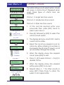
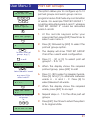
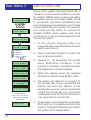
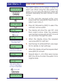
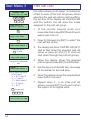
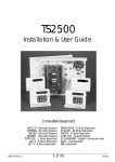
TS2500 Intruder Alarm Control System POWER 10.45 Engineers menu 1 Select Option : 1 2 3 1 2 3 4 5 6 4 5 6 7 8 9 7 8 9 ENT 0 ESC ENT 0 ESC B C A B C A OMIT AREA OMIT AREA POWER 10.45 POWER FUNCTION 1 2 3 1 2 3 4 5 6 4 5 6 7 8 9 7 8 9 ENT 0 ESC ENT 0 ESC B C A B C A OMIT AREA OMIT AREA Managers Operating Manual Contents Overview Glossary of Terms . . . . . . . . . . . . . . . . . . . . . . . . . . . . . . . . . . . . . . . . . . . . 1 Introduction . . . . . . . . . . . . . . . . . . . . . . . . . . . . . . . . . . . . . . . . . . . . . . . . 3 User Menu 2 Introduction . . . . . . . . . . . . . . . . . . . . . . . . . . . . . . . . . . . . . . . . . . . . . . . . 4 View Circuits . . . . . . . . . . . . . . . . . . . . . . . . . . . . . . . . . . . . . . . . . . . . . . . . 5 Setting the System Time . . . . . . . . . . . . . . . . . . . . . . . . . . . . . . . . . . . . . . . 6 Setting the System Date . . . . . . . . . . . . . . . . . . . . . . . . . . . . . . . . . . . . . . . 7 Setup New Users . . . . . . . . . . . . . . . . . . . . . . . . . . . . . . . . . . . . . . . . . . . . . 8 Chime Circuits . . . . . . . . . . . . . . . . . . . . . . . . . . . . . . . . . . . . . . . . . . . . . . 15 Alter 24hr Group . . . . . . . . . . . . . . . . . . . . . . . . . . . . . . . . . . . . . . . . . . . . . 16 Print System Log . . . . . . . . . . . . . . . . . . . . . . . . . . . . . . . . . . . . . . . . . . . . . 17 Alter Circuit Wards . . . . . . . . . . . . . . . . . . . . . . . . . . . . . . . . . . . . . . . . . . . 18 Viewing the System Log . . . . . . . . . . . . . . . . . . . . . . . . . . . . . . . . . . . . . . . 19 Log Event Codes . . . . . . . . . . . . . . . . . . . . . . . . . . . . . . . . . . . . . . . . . . . . 20 Remote Service Options. . . . . . . . . . . . . . . . . . . . . . . . . . . . . . . . . . . . . . . 24 Initiate Remote Service Call . . . . . . . . . . . . . . . . . . . . . . . . . . . . . . . . . . . . 25 Set BST/GMT Dates . . . . . . . . . . . . . . . . . . . . . . . . . . . . . . . . . . . . . . . . . . . 26 User Menu 3 Introduction . . . . . . . . . . . . . . . . . . . . . . . . . . . . . . . . . . . . . . . . . . . . . . . . 27 Time Switches . . . . . . . . . . . . . . . . . . . . . . . . . . . . . . . . . . . . . . . . . . . . . . . 28 Part Set Groups. . . . . . . . . . . . . . . . . . . . . . . . . . . . . . . . . . . . . . . . . . . . . . 31 Use On-line Pad . . . . . . . . . . . . . . . . . . . . . . . . . . . . . . . . . . . . . . . . . . . . . 32 Edit User Names . . . . . . . . . . . . . . . . . . . . . . . . . . . . . . . . . . . . . . . . . . . . . 33 Part Set Text . . . . . . . . . . . . . . . . . . . . . . . . . . . . . . . . . . . . . . . . . . . . . . . . 34 Circuit Text . . . . . . . . . . . . . . . . . . . . . . . . . . . . . . . . . . . . . . . . . . . . . . . . . 35 Circuit Text Library . . . . . . . . . . . . . . . . . . . . . . . . . . . . . . . . . . . . . . . . . . . . 36 Activity Count . . . . . . . . . . . . . . . . . . . . . . . . . . . . . . . . . . . . . . . . . . . . . . . 38 User Menu 4 Introduction . . . . . . . . . . . . . . . . . . . . . . . . . . . . . . . . . . . . . . . . . . . . . . . . 39 Auto-set Timers . . . . . . . . . . . . . . . . . . . . . . . . . . . . . . . . . . . . . . . . . . . . . . 40 Log Search Keys. . . . . . . . . . . . . . . . . . . . . . . . . . . . . . . . . . . . . . . . . . . . . 44 Shunt Groups . . . . . . . . . . . . . . . . . . . . . . . . . . . . . . . . . . . . . . . . . . . . . . . 46 Set Volume Level . . . . . . . . . . . . . . . . . . . . . . . . . . . . . . . . . . . . . . . . . . . . 47 Edit Quick Keys . . . . . . . . . . . . . . . . . . . . . . . . . . . . . . . . . . . . . . . . . . . . . . 48 Code Lock Times . . . . . . . . . . . . . . . . . . . . . . . . . . . . . . . . . . . . . . . . . . . . 49 Additional Text Editing Keys . . . . . . . . . . . . . . . . . . . . . . . . . . . . . . . . . . . . . . . . . . . . . 53 System Records . . . . . . . . . . . . . . . . . . . . . . . . . . . . . . . . . . . . . . . . . . . . . 54 System Records . . . . . . . . . . . . . . . . . . . . . . . . . . . . . . . . . . . . . . . . . . . . . 56 Quick Reference . . . . . . . . . . . . . . . . . . . . . . . . . . . . . . . . . . . . . . . . . . . . 57 Overview Glossary of Terms Alarm Receiving Centre A permanently manned monitoring station used to receive alarm signals from an alarm system. Chime A facility which allows selected detection circuits to generate a two tone sound when triggered. Detection Circuit All detection devices, (e.g. magnetic contacts, movement sensors) are connected to detection circuits. Each circuit is allocated a number which identifies the detection device. For example, a room protected by a movement sensor may be "Circuit 1001", while a door protected by a magnetic contract may be "Circuit 1002". Digital Communicator A signalling device fitted to the system which will transmit alarm information via the telephone line to the alarm receiving centre. Downloading A process which allows the alarm system to be remotely interrogated and programmed using a computer and modem. Duress A means of entering a passcode which generates a silent alarm via the signalling device (if fitted) to a the alarm receiving centre. Entry Time A pre-set time delay to allow the user to enter the protected area and access the remote keypad without causing an alarm. Event Log A record of system activity which is stored in memory (maximum of 4000 events). Exit/Entry Route The route which must be used when entering or leaving the protected area when the alarm system is being set. Exit Terminator An external push button switch used to complete the setting of the alarm system. Exit Time A pre-set time delay to allow the user to leave the protected area after initiating the setting procedure. Final Exit The door or detector used when leaving and entering the protected area. Full Set The state of the alarm system when it is protecting all areas of the premises. 1 Overview Glossary of Terms Master User The user(s) who has the authority for assigning new users to the alarm system. Modem A device for transmitting and receiving data to and from a computer via the telephone line. Omit To intentionally exclude the monitoring of one or more detection circuits when setting the alarm system. P.A. (Panic Alarm) An emergency push button switch used to activate an alarm. The alarm signal will also be transmitted to the alarm receiving centre if a signalling device is fitted to the alarm system. Part Set The state of the alarm system when it is protecting part of the premises. Passcode A unique number which must be entered before the alarm system can be operated. Remote Keypad A device located away from the main control panel that is used to operate the alarm system. Reset The action required to return the alarm system to its normal state after an alarm condition. Set To arm one or more wards. System Open The status of the system when all wards are unset. Tamper Alarm An alarm caused by the system being physically interfered with. 24hr Circuit A circuit that is monitored at all times. Unset To disarm one or more wards. Users Persons allocated a passcode which allows them to operate the alarm system. Wards A group of detection circuits that can be set or unset independently of each other. 2 Overview Introduction This manual describes the more advanced operating procedures for your alarm system and is normally used by the master or manager users. For details of the basic operating procedures refer to the "Operators Manual". User Menus The TS2500 has four separate user menus and each menu has between 9 and 12 options. User menus 2, 3 and 4 are covered by this manual. User menu 1 is covered in the Operators Manual. Access to user menus and options will depend on your user access level. For details on setting user levels, see "Setup New Users" on page 8. 3 User Menu 2 ? ? ? ? ENT User menu 1 Select option :ENT User menu 2 Select option :- A C = Forwards = Backwards 1 User menu 2 View circuits 2 User menu 2 Set system time 3 User menu 2 Set system date 4 User menu 2 Setup new users 5 User menu 2 Chime circuits 6 User menu 2 Alter 24hr group 7 User menu 2 Print system log 8 User menu 2 Alter cct wards 9 User menu 2 View system log 0 User menu 2 Rem service opt. A User menu 2 Start call back C User menu 2 Set BST/GMT date 4 Introduction To access user menu 2 enter your passcode, then press [ENT] to select user menu 1. Now press [ENT] again to select user menu 2.There are 12 menu options and access to these options will depend on your access level. Each option has a "hot-key" which allows you to select the required option by pressing the relevant hot-key number, e.g. the "View circuits" option is assigned to key [1], so to select this option press [1] followed by [ENT]. Alternatively you Cain use the [A] and [C] keys to scroll forwards and backwards through the available options. As you press the [A] and [C] keys the bottom line of the display will show the selected menu option. When you have found the required option press the [ENT] key to perform the option. To leave user menu 2 and return to user menu 1 simply keep pressing the [ESC] key until the display shows "User menu 1". User Menu 2 View Circuits This option allows you to ascertain the status of each detection circuit, The status for each circuit may be as follows: Healthy - the normal status of a detection circuit, I.e. door closed or detector healthy. Active - This is the alarm status of a detection circuit, i.e. door open or detector in alarm. Tamper - This is the tamper open circuit status of a detection circuit, i.e. alarm cable cut or a cover removed from a detector. SYSTEM OPEN 18:10 Sun 01 JAN ? ? ? ? ENT ENT User menu 2 Select option :- 1 User menu 2 View circuits ENT Front Door 0001 Healthy Enter circuit No. or A = Next circuit C = Previous circuit e.g. 2002 Office window 2002 Active ESC ESC SYSTEM OPEN 18:10 Sun 01 JAN Shorted - This is the short circuit status of a detection circuit, i.e. alarm cable shorted or damaged. 1. At the remote keypad enter your passcode then press [ENT] twice to select user menu 2. 2. Press [1] followed by [ENT] to select the view circuits option. 3. The display will show circuit 0001 and its current status. 4. Select the circuit you require to view by either entering the circuit number or by pressing the [A] and [C] keys to scroll up and down through the circuits. 5. Press [ESC] three times to return the system to its original state. 5 User Menu 2 Setting the System Time This option allows you to set the system time The system can also be programmed to automatically add and subtract an hour when British Summer Time starts and ends, see "Set BST/GMT Dates "on page 26. SYSTEM OPEN 18:10 Sun 01 JAN ? ? ? ? ENT ENT User menu 2 Select option :- 2 User menu 2 Set system time ENT Enter new time: 00:00 BST Enter new time e.g. 1810 for 6:10 pm Enter new time: 18:10 BST B to alternate between BST & GMT Enter new time: 18:10 GMT ENT User menu 2 Select option :ESC ESC SYSTEM OPEN 18:10 Sun 01 JAN 6 1. At the remote keypad enter your passcode then press [ENT] twice to select user menu 2. 2. Press [2] followed by [ENT] to select the set system time option. 3. The display will show the current time. Enter the new time in 24hr format, e.g. 1810 for 6:10 PM. 4. The display also shows the current time zone, i.e. BST or GMT. Press [B] to alternate between BST and GMT. 5. When the display shows the correct time and time zone, press [ENT] to accept. 6. Press [ESC] twice to return the system to its original state. User Menu 2 Setting the System Date This option allows you to set the system date. It is displayed in a day/date / month format on all LCD remote keypads. SYSTEM OPEN 18:10 Sun 01 JAN ? ? ? ? ENT ENT User menu 2 Select option :- 3 User menu 2 Set system date ENT Enter new date: 01/01 1. At the remote keypad enter your passcode then press [ENT] twice to select user menu 2. 2. Press [3] followed by [ENT] to select the set system date option. 3. The display will show the current date. Enter the new date in a date/month format, e,g. 2804 for the 28th April. 4. When the display shows the correct date Enter new date e.g. 2804 for 28 April press [ENT] to accept. The display will show the current day setting, Sunday -Saturday. Enter new date: 28/04 5. To change the day press [1] for Sunday,[2] for Monday, [3] for Tuesday etc. ENT Today is : >Su............ Select the day [1] = Sunday [7] = Saturday e.g. 3 for Tuesday 6. Then the display shows the correct day press [ENT] to accept. 7. Press [ESC] twice to return the system to its original state. ENT User menu 2 Select option :ESC ESC SYSTEM OPEN 18:10 Tue 28 APR 7 User Menu 2 Setup New Users The TS2500 allows up to 199 users to Operate the alarm system, each user is assigned a user type, passcode and ward access. User 001 is the master user which has a default setting of 5678. User Types The following user types are available: Master This user type has access to all fours our user menus and options. A master user is also a global user which allows the user to set and unset their assigned wards from any remote keypad. Manager This user type has access to "User menu 1" and "User menu 2". A manager user is also a global user which allows the user to set and unset their assigned wards from any remote keypad. Standard Global This user type has access to "User menu 1".A standard global user is also a global user which allows the user to set and unset their assigned wards from any remote keypad. Standard Ward This user type has access to "User menu 1".A standard ward user can only set and unset their assigned wards from a remote keypad that is assigned to the same word(s) that they are trying to set/unset, For example if the user is assigned to wards A and B,and operates the system from a keypad assigned only to ward B. the user would only have the option to set/unset ward B. Reset Only This user type allows 24hr alarms to be reset and access to "User menu 1" options 1 to 9. A reset only user is also a global user type which allows the user to reset 24hr alarms from any remote keypad. 8 User Menu 2 Setup New Users (Cont.) Panic Code This user type does not have access to any user menus nor can it be used to set and unset the system. When this user code is entered a "Panic Alarm"' is transmitted to the alarm receiving centre and the external sounder(s) and strobe light(s) are also activated. Duress Code This user type operates in the same way as a standard global user, but when the passcode is used a silent "Panic Alarm" is transmitted to the alarm receiving centre. NOTE: if enabled by your alarm company all users can generate a "Duress" alarm by entering their passcode with the first two digits reversed (e.g. for a passcode of 2580 enter 5280 to generate a "Duress" alarm). Access This user type does not have access to any user menus nor can it be used to set and unset the system, When this user code is entered it will Operate specific outputs which in turn can be used to Operate an electric door strike or similar. Shunt This user type does not have access to any user menus nor can it be used to set and unset the system. When this user code is entered it will isolate a predefined group of detection circuits. When the code is re-entered it will reinstate the group. Set Only This user type operates in the same way as a standard global user, except that it only allows setting of wards. Not in use This user type does not perform any operation. Select this user type to delete an existing user. 9 User Menu 2 Setup New Users (Cont.) User Wards Each user must be assigned to wards. Once assigned to wards the user can then set, unset and reset the wards they have been given access to. Auto Sets wards Wards that are assigned as auto set will automatically be selected for setting when choosing the "SET WARDS" option. If a ward is not assigned as auto set the user is given the choice to select the ward at the time of setting. Auto Unset Wards Wards that are assigned as auto unset will automatically be selected for unsetting when choosing the "UNSET WARDS" option. If a ward is not assigned as auto unset the user is given the choice to select the ward at the time of unsetting. Customising Users Access to user menus is initially defined by the user type, e.g. the manager user has access to user menus 1 and 2, and a standard global user has access to user menu 1 only. However, each user can be customised so that individual options within user menus are available or restricted, e.g. user 002 could be given the initial type of standard ward, then customised to allow the user to access all user menus and options. This would effectively create a master user that can only set and unset their assigned wards from a remote keypad that is assigned to the same ward(s) that they are trying to set/unset. 10 User Menu 2 SYSTEM OPEN 18:10 Sun 01 JAN ? ? ? ? ENT ENT User menu 2 Select option :- 4 User menu 2 Setup new users ENT Define new users User no. 002 Enter user no. ENT Enter new code ---- Enter new passcode ENT User 002 is type Not in use Select new user type: 1 = Master 2 = Manager 3 = Standard Global 4 = Standard Ward 5 = Reset Only 6 = Panic Code 7 = Duress Code 8 = Access 9 = Shunt 0 = Set Only B = Not Used ENT Setup New Users (Cont.) 1. At the remote keypad enter your passcode then press [ENT] twice to select user menu 2. 2. Press [4] followed by [ENT] to select the Setup new users option. 3. The display will show the next available user number. Pressing [B] will show the number of users that are currently programmed into the panel, pressing any key will return to the previous display. 4. If required enter the user number you require or press [ENT] to accept the next available user. 5. The display will prompt you to enter a new passcode. Enter the code followed by [ENT]. 6. If the new code is not accepted the display will show "NOT ACCEPTED try a different code". Enter a different passcode followed by [ENT]. 7. The display will show the selected user and its current user type. Press [1] - [9] or use the [A] and [C] keys to scroll through the user types. 8. When the display show the required user type, press [ENT] to accept. (Continued Over) 11 User Menu 2 User 002 wards A,*,*,*,.,.,., 1 8 Select/deselect wards ENT 002 Auto sets:A,*,*,*,.,.,., 1 9. The display will now show the wards assigned to the selected user. To select / deselect wards A - H press [1] - [8]. To select / deselect wards I - P press [A] then [1] - [8]. 10. When you have the required wards displayed press [ENT] to accept. 11. The display will now show the auto set 8 Select/deselect wards ENT 002 Auto unset:A,*,*,*,.,.,., 1 Setup New Users (Cont.) wards assigned to the selected user. To select or deselect wards A - H press [1] [8]. To select wards I - P press [A] then [1] [8] . 12. When you have the required auto set 8 Select/deselect wards ENT [ENT] to customise user ESC wards displayed press [ENT] to accept. 13. The display will now show the auto unset wards assigned to the selected user. To select or deselect wards A - H press [1] [8] . To select wards I - P press [A] then [1] [8]. Define new users User no. 003 14. When you have the required auto unset Repeat for other users or 15. The display will prompt you to press [ENT] ESC ESC ESC SYSTEM OPEN 18:10 Sun 01 JAN wards displayed press [ENT] to accept. to customise the user. If required the user c a n b e cu s t omis ed b y p r es s ing [ENT],otherwise press [ESC]. For details on Customising a user see page 53. 16. The display will show the next available user number. If required repeat for other users or press [ESC] three times to return the system to its original state. 12 User Menu 2 Customizing a user code Setup New Users (Cont.) When setting up a new user code it is possible to customise the user so that options for user menus are added or removed for the selected user. The table below shows all four user menus and the options available. Key User Menu 1 User Menu 2 User Menu 3 User Menu 4 0 Set/Unset Menu Rem Service Opt Activity Count Code Lock Times 1 Bell Test View Circuits Time Switches Auto Set Timers 2 Walk Test Set system time Part Set Groups 3 Remote Reset Set System Date Use On-line Pad 4 Change Code Setup New Users Edit User Names 5 Enable Chime Chime Circuits Part Set Text Log Search Keys 6 24hr Omit Alter 24hr Group Circuit Text Shunt Groups 7 Omit Zones Print System Log 8 Silent set Alter cct Wards Set Volume Level 9 View System Log Edit Quick Keys A Start Call Back B C Set BST/GMT Date From step 14 on previous page. [ENT] to customise user ENT 9 selecct/deselect user menu1 options ENT to Customise user". 2. The display will show the options Menu 1 options:> 0123456789... 0 1. Press [ENT] when the display shows "[ENT] available in user menu 1. 3. Press [0] - [9] to select or deselect the individual options. Press [ENT] to accept. (Continued Over) 13 User Menu 2 Menu 2 options: > 0123456789... 0 9 A C Selecct/deselect user menu 2 options ENT Menu 3 options: > 012*456...... 0 6 Selecct/deselect user menu 3 options ENT 8 Selecct/deselect user menu 4 options ENT Define new users User no. 003 Repeat for other users or ESC ESC ESC SYSTEM OPEN 18:10 Sun 01 Jan 14 4. The display will show the options available in user menu 2. 5. Press [0] - [9], [A] or [C] to select or deselect the individual options. Press [ENT] to accept. 6. The display will show the options available in user menu 3. 7. Press [0] - [6] to select or deselect the individual options. Press [ENT] to accept. 8. The display will show the options available in user menu 4. Menu 4 options: > 01...567*.... 0 Setup New Users (Cont.) 9. Press [0] - [8] to select or deselect the individual options. Press [ENT] to accept. 10. The display will show the next available user number. If required repeat for other users or press [ESC] three times to return the system to its original state. User Menu 2 SYSTEM OPEN 18:10 Sun 01 JAN ? ? ? ? ENT ENT User menu 2 Select option :- 5 User menu 2 Chime circuits ENT Front Door 0001 Disabled A C Enter circuit No. or = Next circuit = Previous Circuit e.g. 2001 Enter new code ---- User 002 is type Not in use Chime 1: A single two-tone sound. Chime 2: A double two-tone sound. Chime 3: A triple two-tone sound. 1. At the remote keypad enter your passcode then press [ENT] twice to select user menu 2. 2. Press [5] followed by [ENT] to select the chime circuits option. 3. The display will show circuit 0001 and its current chime status. chime by either entering its number or by pressing the [A] and [C] keys to scroll up and down through the circuits. = Chime 1 = Chime 2 = Chime 3 = Disabled 5. When the display shows the required e.g. press 1 6. Press [1] - [3] to select chime 1 - 3 or [0] to Office Door 2001>Chime 1 ENT This option allows you to select which circuits will cause a chime tone if triggered when unset. Three types of chime tone are available: 4. Select the circuit you require to put on ENT 1 2 3 0 Chime Circuits to accept Office Door 2001 Chime 1 Repeat for other circuits, if required or ESC ESC circuit, press [ENT] to edit. disable chime. 7. When the display shows the required setting press [ENT] to accept. 8. Repeat steps 4 - 7 for other circuits or press [ESC] three times to return the system to its original state. ESC SYSTEM OPEN 18:10 Sun 01JAN 15 User Menu 2 Alter 24hr Group This option allows you to define which wards are allocated to the 24hr group. Once a ward is assigned to the group all "24hr" and "Auxiliary" circuits within the ward(s) can be isolated by any user that has access to user menu 1 option 6 (24hr Omit). SYSTEM OPEN 18:10 Sun 01 JAN ? ? ? ? ENT ENT User menu 2 Select option :- 6 User menu 2 Alter 24hr group 1. At the remote keypad enter your ENT Wards 24hr group *,*,*,*,.,.,.,. 1 8 to select & deselect wards e.g. press [1] to select ward A Wards 24hr group A,*,*,*,.,.,.,. ENT User menu 2 Select option :ESC For example, your site may have several loading bay doors within the Warehouse area. Each door is then protected by 24hr circuit. The Warehouse area is assigned to ward A. Therefore, if ward A was assigned to the 24hr groups all 24hr circuit within ward A would be isolated when a user selected the "24hr Omit" option (see Operators Manual). ESC SYSTEM OPEN 18:10 Sun 01JAN passcode then press [ENT] twice to select user menu 2. 2. Press [6] followed by [ENT] to select the alter 24hr group option. 3. The display will show which wards are currently assigned to the 24hr group. 4. Press [1] - [8] to select or deselect wards. Press [A] and [C] to alternate between wards A - H and I - P. 5. When the display shows the required wards, press [ENT] to accept. 6. Press [ESC] twice to return the system to its original state. 16 User Menu 2 Print System Log The system log stores 4000 events. If a printer is connected to your alarm system it is possible to print any number of log events. SYSTEM OPEN 18:10 Sun 01 JAN ? ? ? ? ENT ENT User menu 2 Select option :- 7 User menu 2 Print system log ENT How many events 0030 Enter the number of events ENT With offset of: 0000 Enter the offset required ENT Printing User menu 2 Select option :ESC ESC SYSTEM OPEN 18:10 Sun 01 JAN When you select a number of events to be printed, the panel starts at event 4000 (the most recently logged event) and works backwards. For example if you request a printout of 100 events, the printer will print events 3900 - 4000. By specifying an offset you can print the selected number of events from the offset point rather then event 4000. For example, if you specify 100 events with an offset of 1 000, the printer will print events 2900 - 3000. 1. At the remote keypad enter your passcode then press [ENT] twice to select user menu 2. 2. Press [7] followed by [ENT] to select the print system log option. 3. The display will prompt you to enter how many events you require to be printed. 4. Enter the number you require. The display will now prompt you to enter an offset. Enter the offset value if required. 5. Press [ENT] to start printing. 6. To Cancel printing select 0000 at step 3. 7. Press [ESC] twice to return the system to its original state. 17 User Menu 2 SYSTEM OPEN 18:10 Sun 01 JAN ? ? ? ? ENT ENT User menu 2 Select option :- 8 User menu 2 Alter cct wards ENT 0001 Night A............... Enter circuit No. or A =Scroll up C =Scroll down e.g. 2001 2001 Night .B.............. ENT 8 to select & deselect wards e.g. Press [1] to select ward A 2001 Night A,B,.,.,.,.,.,. ENT 2001 Night AB.............. Repeate for other circuits, if required or ESC ESC ESC SYSTEM OPEN 18:10 Sun 01 JAN 18 Normally your alarm company will assign detection circuits in to wards. It is advised that you only use this option if you are very familiar with your alarm system and the concept of wards, When selecting this option you can only affect wards that are assigned to your passcode. 1. At the remote keypad enter your passcode then press [ENT] twice to select user menu 2. 2. Press [8] followed by [ENT] to select the alter circuit wards option. 3. The top line of the display will show circuit 0001 and its circuit type. The bottom line will show the wards that the circuit is assigned to. 4. Select the circuit you require to alter by 2001 Night *,B,*,*,*,*,*,* 1 Alter Circuit Wards either entering its number or by pressing the [A] and [C] keys to scroll up and down through the circuits. 5. When the display shows the required circuit, press [ENT] to edit. 6. Press [1] - [8] to select or deselect wards. Press [A] and [C] to alternate between wards A - H and I - P. Press [B] to select/deselect all wards. 7. When the display shows wards, press [ENT] to accept. 8. Repeat steps 4 - 7 for other circuits if required or press [ESC] three times to return the system to its original state. User Menu 2 Viewing the System Log This option allows you view the system log. The [A] and [C] keys allow you to scroll backwards and forwards through the log events. The log event codes are shown on pages 20 - 23. SYSTEM OPEN 18:10 Sun 01 JAN ? ? ? ? ENT ENT User menu 2 Select option :- 9 User menu 2 View system log PASSCODE 001 17:17.04 29/04 =Scroll forwards =Scroll dackwards ESC ESC passcode then press [ENT] twice to select user menu 2. 2. Press [9] followed by [ENT] to select the view log option. 3. The display will show the most recent event. 4. Use the [A] and [C] keys to scroll through ENT A C 1. At the remote keypad enter your ESC SYSTEM OPEN 18:10 Sun 01 JAN the log. The [B] key is used to display additional event information, e.g. if the event is a ward related event, pressing [B] will display the ward information. 5. When finished viewing the log, press [ESC] three times to return the system to its original state. � When viewing the system event log you can use the log search keys to display specific events that meet a Certain criteria. The log search keys are configured in user menu 4, see page 44. 19 User Menu 2 Event —- NO EVENT —#### ACTIVATED #,## LEC LOST ### LEC or REM’S #,## NODE ADDED Log Event Codes Description No event Monitored circuit activated Network #, device No. ## is a LEC that has been removed The number of LEC or REM’s logged on to system after a re-learn Network #, device No. ## is a TS900 Node that has been added to the system #,## NODE LOST Network #, device No. ## is a TS900 Node that has been removed ### NODE’S The number of TS900 Nodes logged on to the system after a re-learn ### XNODE’S The number of XNodes logged on to the system after a re-learn #### OFF TEST Circuit number #### taken off test #### OMITTED Circuit number #### omitted #### REINSTATED Circuit number #### reinstated #,## REM ADDED Network #, device No. ## is a remote keypad that has been added to the system #,## REM LOST Network #, device No. ## is a remote keypad that has been removed #### SHUNTED Circuit number #### shunted #,## XNODE ADDED Network #, device No. ## is a XNode that has been added to the system #,## XNODE LOST Network #, device No. ## is a XNode that has been removed 24Hr ALARM #### 24hr alarm from circuit number #### 24Hr OMITTED: 24Hr group omitted in wards:- A - P 24Hr REINSTATED: 24Hr group reinstated in wards:- A - P 24Hr WARDS: 24hr Alarm on wards:- A - P ABORT ON WARDS:Alarm aborted on wards:- A - P ABORTED ERRORS Remote service errors ACCESS ### Access passcode ### entered. ACCESS FAILED Access failed due to code lock in operation ALARM #### Alarm from circuit number #### ALARM WARDS:Alarm in wards:- A - P AUTOSET # OFF Autoset timer 1-3 off AUTOSET # ON Autoset timer 1-3 on AUXILIARY #### Auxiliary alarm from circuit number #### AUXILIARY # TAMP Auxiliary 1 or 2 tamper AUXILIARY FUSE Auxiliary Fuse failed BATTERY FAULT Battery disconnected or voltage level below 9.5V 20 User Menu 2 Event Log Event Codes (Cont.) Description BATTERY RESTORE BEAM PAIR #### BELL BOX TAMPER BELL TESTED:- Battery restored to healthy condition First activation of a beam pair circuit number #### External sounder/bell tamper Bell tested for wards:- A - P BELLS ACTIVE:CALL ABORTED CALLED No. # CALLING BACK No. # CCT ON TEST #### CCT TESTED #### CCTS REINSTATED CIRCUITS SHUNTED CODE LOCK # OFF CODE LOCK # ON CODE LOCKED ### Bell active for wards:- A - P Remote service call aborted Remote service call initiated via panel to remote PC 1, 2 or 3 Remote service call requested via PC to “Call back No” 1, 2 or 3 Circuit number #### put on test Circuit number #### tested during walk test routine Circuits reinstated with a shunt code Circuits shunted with a shunt code Code lock number # is off Code lock number # is on User number ### attempted to use their passcode whilst locked-out CODE TAMPER COMMS FAILED COMMS SUCCESSFUL DATE CHANGED DEFAULT USER ### DEFERRED SET:DIGI-COM FITTED DIGI/MODEM LOST DIGI/MODEM RESET DURESS CODE ### ENGINEER ARRIVES ENGINEER DEPARTS ENTRY #### ENTRY TIME-OUT:ENTRY WARDS:EXIT CANCELLED:EXIT STARTED:FACTORY RESTART FIRE ALARM #### FIRE WARDS:FIRST KNOCK #### Keypad locked out for 5 minutes due to invalid entry of code Plug-on digicom failed to communicate with ARC Plug-on digicom communicated successfully with the ARC System date changed User 001 defaulted to 5678 Deferred set on wards:- A - P Plug-on digicom fitted Plug-on digicom or modem removed Plug-on digi-modem reset Duress alarm from user number ### Engineer is logged on the system Engineer is logged off the system Entry mode started from circuit number #### Entry mode timed out for wards:- A - P Entry on wards:- A - P Exit mode cancelled for wards:- A - P Exit mode started for wards:- A - P Factory default loaded Fire alarm from circuit number #### Fire alarm on wards:- A - P First activation of circuit number #### (circuit with Double-Knock attribute) 21 User Menu 2 Event Log Event Codes (Cont.) Description From Remote #,## Quick set perform from remote keypad (# = Network, ## =device No) Hi Security SET: Wards A - P set using “High Security” feature LEC #,## TAMPER Network #, LEC number ## lid tamper alarm LINE RESTORE Telephone line restored to healthy LINK ESTABLISHED Remote link via PC established MAINS POWER OFF Mains power removed from control panel MAINS POWER ON Mains power applied to control panel MENU TIMEOUT ### User number ### entered their passcode and did not selected any functions MODEM FITTED Plug-on digi-modem fitted MODEM LOCK-OUT Modem locked-out (4 failed attempts made via Lineload) NODE ### R# ADD Remote keypad added to XNode NODE ### R# LOST Remote keypad removed from XNode NODE ### R# TAMP Remote keypad lid tamper from remote on XNode ON-LINE ENDED Remote service call ended (PC and Lineload) ON-LINE TO No.# On-line to remote PC ON-SITE RESTART On-site restart NODE #,## FUSE TS900 Node fuse failed NODE #,## TAMPER TS900 Node lid tamper NODE SHUNT #### Circuits shunted on a Node PA ALARM #### PA Alarm from circuit number #### P.A CODE ### PA code from user number ### PA WARDS:PA alarm on wards:- A - P PANEL LID TAMPER Control panel lid tamper PASSCODE ### User number ### entered their passcode PAYMENT EXPIRED System payment timer has expired PC CONNECTED PC connected to control panel (PCI/DCI) PC DISCONNECTED PC disconnected from control panel (PCI/DCI) PHONE LINE FAULT Telephone line fault detected QUICK SET KEY # Quick set key A, B or C activated Q.SET ABORTED Quick set key aborted REARM ON WARDS:- Wards:- A - P re-armed REINSTATED WARDS Wards A - P reinstated REM #,## TAMPER Remote keypad lid tamper REM RESET ACTIVE Remote reset via the REM RESET input terminal (RedCARE) REM RESET FAILED Remote Reset failed 22 User Menu 2 Event Log Event Codes (Cont.) Description REM SERVICE CALL RESET WARDS:SEC. KEY #### SERVICE CALL END SERVICE REQUIRED SET FAIL WARDS:SET FAIL #### SET NO ACTIVITY Remote service call in progress User or engineer has reset wards:- A - P Security key operated on circuit number #### Remote service finished System requires a service visit (Service Timer expired) Set fail for wards:- A - P Set fail caused by circuit #### System was set with inactive circuits (circuits with the activity attribute) SET WARDS:Wards set:- A - P SET WITH L.FLT:Wards A - P set with a line fault present SETTING DEFERRED Setting deferred SHUNT CODE ### Shunt code number ### enter their passcode SHUNT KEY #### Shunt key circuit #### operated SYSTEM RELEARN A system relearn has been performed T.SWITCH # OFF Time switch number # off T.SWITCH # ON Time switch number # on TAMPER #### Tamper alarm from circuit number #### TAMPER WARDS:Tamper alarm on wards:- A - P TEST FAIL #### Circuit number #### failed whist on test TEST TOTAL #### Total number of circuit tested during walk test TIME CHANGED System time changed UNSET WARDS:Wards:- A - P unset USER ### DELETED User number ### deleted WALK TESTED:Wards:- A -P walk tested WARD KEY #### Ward key circuit #### operated WARDS LOCKED:Wards:- A - P locked via security key circuit WARDS UNLOCKED:- Wards:- A - P unlocked via security key circuit XNODE #,## FUSE XNode fuse failed XNODE #,## TAMP XNode lid tamper 23 User Menu 2 SYSTEM OPEN 18:10 Sun 01 JAN ? ? ? ? ENT ENT User menu 2 Select option : 0 User menu 2 Rem service opt. Rem service call is ENABLED B to alternate between ENABLED & DISABLED programmed the system such that remote servicing is enabled at all times the display will show "ENG. ENABLED" when selecting this menu option. passcode then press [ENT] twice to select user menu 2. 2. Press [0] followed by [ENT] to select the remote service options. 3. Press [B] to alternate between ENABLED ENT User menu 2 Select option : ESC SYSTEM OPEN 18:10 Sun 01 JAN 24 If your alarm system has been fitted with a modem, the alarm Company can dial into the system and remotely read and write data from the control panel. For added security your alarm system can be programmed so that a user has to authorise any write commands. When the "Remote service call" option is set to "ENABLED" the alarm company can dial into the system at any time and read and write delta from the control panel. When the "Remote service call" option is set to "DISABLED" the alarm company can still dial into the system at any time but Corn only read data from the control panel. Once a user has enabled the "Remote service call" option the system will automatically revert it to disabled at 3:00 am. If your alarm company has 1. At the remote keypad enter your ENT ESC Remote Service Options and DISABLED. Press [ENT] to accept. 4. Press [ESC] twice to return the system to its original state. User Menu 2 Initiate Remote Service Call If your alarm system is fitted with a modem, it is possible for an authorised user to initiate an upload sequence to a remote site (normally the alarm company or central station). Once the Communication link is established, the remote site can read and write data from the control panel. This feature is only compatible with Menvier Lineload software version 2.1 or above. � Only select this option when requested by your alarm company. If this option is selected without authorisation from the alarm company the modem may not connect with the remote site. 1. At the remote keypad enter your SYSTEM OPEN 18:10 Sun 01 JAN ? ? ? ? ENT ENT User menu 2 Select option :- A User menu 2 Start call back ENT 01811234567 Call No.1 Office 1 2 3 B ENT = Dial No.1 = Dial No.2 = Dial No.3 = Dial this number to start call back SYSTEM OPEN 18:10 Sun 01 JAN passcode then press [ENT] twice to select user menu 2. 2. Press [A] followed by [ENT] to select the start call back option. 3. Pressing [1] - [3] will display the remote site(s) telephone number(s). You will be advised by your alarm company as to which number to select. If the number is not listed, press [B] and enter the telephone number required. 4. When the display shows the required telephone number press [ENT] to start the call back sequence. 5. The system will automatically return to its original state. 25 User Menu 2 Set BST/GMT Dates This option allow you to specify the dates at which British Summer Time (BST) starts and ends. The system will then add one hour to the system time at 2:00 am on the BST date and subtract one hour at 2:00 am on the Greenwich Mean Time (GMT) date. These dates are set by the government and do vary from year to year. The dates Can be found in most good diaries. SYSTEM OPEN 18:10 Sun 01 JAN ? ? ? ? ENT ENT User menu 2 Select option :- C User menu 2 Set BST/GMT date ENT Enter BST date: 31/03 Enter BST date e.g. 31/03 ENT Enter GMT date: 27/10 Enter GMT date e.g. 27/10 User menu 2 Select option :ESC SYSTEM OPEN 18:10 Tue 01 JAN 26 passcode then press [ENT] twice to select user menu 2. 2. Press [C] followed by [ENT] to select the set BST/GMT date option. 3. The display will prompt you to enter the BST date. Enter the date in a date/month format, e.g. 31/03 for the 31 March. 4. When the display shows the required BST date press [ENT] to accept. 5. The display will prompt you to enter the GMT d a t e. E n t er t h e d a t e in a date/month format, e.g. 27/10 for the 27 October. 6. When the display shows the required GMT date press [ENT] to accept. ENT ESC 1. At the remote keypad enter your 7. Press [ESC] twice to return the system to its original state. User Menu 3 User menu 2 Select option :ENT User menu 3 Select option :- A C = Forwards = Backwards 1 User menu 3 Time switches 2 User menu 3 Part set groups 3 User menu 3 Use on-line pad 4 User menu 3 Edit User Names 5 User menu 3 Part set text 6 User menu 3 Circuit text 0 User menu 3 Activity count Introduction User menu 3 is accessed by pressing the [ENT] key whilst user menu 2 is selected. There are 7 menu options and access to these options will depend on your access level. Each option has a "hot-key" which allows you to select the required option by pressing the relevant hot-key number, e.g. the "Part set text" option is assigned to key [5], so to select this option press [5] followed by [ENT]. Alternatively you can use the [A] & [C] keys to scroll forwards and backwards through the available options. As you press the [A] & [C] keys the bottom line of the display will show the selected menu option. When you have found the required option press the [ENT] key to perform the option. To leave user menu 3 and return to user menu 2 simply keep pressing the [ESC] key until the display shows "User menu 2". Menu options 7, 8 and 9 are only available to the alarm company engineer. 27 User Menu 3 Time Switches The TS2500 alarm system has three programmable time switches. Each time switch can be programmed with up to three separate on/off times and made to operate on any day of the week The time switches can be assigned to outputs which in turn can be used to control internal or external lighting (or similar). Selecting time switches When you select the time switch option from user menu 3, "Time switch 1 " is automatically selected. To select other time switches proceed as follows: SYSTEM OPEN 18:10 Sun 01 JAN ? ? ? ? ENT ENT ENT User menu 3 Select option : 1 User menu 3 Time switches ENT Time switch 1 Select option: 28 A = Time Switch 1 B = Time Switch 2 C = Time Switch 3 1. At the remote keypad enter your passcode then press [ENT] three times to select user menu 3. 2. Press [1] followed by [ENT] to select the time switch options. 3. The display will show "Time switch 1" is selected. 4. Press [A] to select "Time switch 1", [B] to select "Time switch 2" and [C] to select "Time switch 3". 5. When the required time switch is selected you may now configure it as desired. User Menu 3 Time Switches (Cont.) Programming the on-times To program the first, second and third on-times proceed as follows: Time switch 1 Select option : 1 = On-time 1 2 = On-time 2 3 = On-time 3 Time switch 1 On-time 1 21:00 Enter on-time e.g. 21:00 ENT Time switch 1 Select option :- 1. Ensure that the required time switch is selected. 2. Press [1] for the first on-time, [2] for the second on-time and [3] for the third on-time. 3. The display will show the current on-time setting. Enter the required time in a 24hr format, e,g, 21:00 for 9:00 PM. 4. When the display shows the required time press [ENT] to accept. Programming the off-times To program the first, second and third off-times proceed as follows: 1. Ensure that the required time switch is selected. Time switch 1 Select option : 4 = Off-time 1 5 = Off-time 2 6 = Off-time 3 Time switch 1 Off-time 1 23:00 Enter off-time e.g. 23:00 2. Press [4] for the first off-time, [5] for the second off-time and [6] for the third off-time. 3. The display will show the current off-time setting. Enter the required time in a 24hr format, e.g. 23:00 for 11:00 PM. 4. When the display shows the required time press [ENT] to accept. ENT Time switch 1 Select option :- 29 User Menu 3 Time Switches (Cont.) Programming the days of operation To program the days of operation for the first, second and third on/off timers, proceed as follows: Time switch 1 Select option : 7 = Operation of 1st 8 = Operation of 2nd 9 = Operation of 3rd 1 Operates on : > Su ........... Enter days by pressing [1] to [7] e.g. press 1 to select Sunday ENT Time switch 1 Select option :- 1. Ensure that the required time switch is selected. 2. Press [7] for the first timer, [8] for the second timer and [9] for the third timer. 3. The display will show the current days of operation. Enter the required days of 4. operation by pressing [1] - [7] to select or deselect the days of the week, e.g. press 5. [1] to select Sunday. 6. When the display shows the required days of operation press [ENT] to accept. Manually overriding the timer Each time switch can be manually switched on or off as follows: 1. Ensure that the required time switch is Time switch 1 Select option : 0 Time switch 1 > output is OFF B to alternate between ON and OFF ENT Time switch 1 Select option :- 30 selected. 2. Press [0], the display will show the current state of the selected time switch. 3. Press [B] to alternate between ON and OFF. 4. When the display shows the required days of Operation press [ENT] to accept. User Menu 3 SYSTEM OPEN 18:10 Sun 01 JAN ? ? ? ? ENT ENT ENT User menu 3 Select option :- 2 User menu 3 Part set groups ENT PART SET GROUP 0 A............... 0 9 to select part set groups, e.g. [1] ENT to edit PART SET GROUP 1 A,*,*,*,.,.,.,. 1 8 Select/deselect wards e.g. press [3] to select ward C PART SET GROUP 1 A,*,C,*,.,.,.,. PART SET GROUP 1 A.C............. Repeate for other part set groups or ESC This option allows you to configure up to 10 part set groups and each group can be programmed so that it sets any combination of wards. For example "PART SET GROUP 1 " could be allocated wards A and C, whereas "PART SET GROUP 2" could be allocated wards A and B. 1. At the remote keypad enter your passcode then press [ENT] three times to select user menu 3. 2. Press [2] followed by [ENT] to select the part set groups option. 3. The display will show "PART SET GROUP 0"and the current ward configuration. 4. Press [1] - [9] or [0] to select part set groups 1 - 9 or 10. 5. When the display shows the required part-set group, press [ENT] to edit. 6. Press [1] - [8] to select or deselect wards. Press [A] and [C] to alternate between wards A - H and I - P. Press [B] to select/deselect all wards. 7. When the display shows the required ENT ESC Part Set Groups ESC wards, press [ENT] to accept. 8. Repeat steps 4 - 7 for the other part set groups. 9. Press [ESC] four times to return the system to its original state. SYSTEM OPEN 18:10 Sun 01 JAN 31 User Menu 3 SYSTEM OPEN 18:10 Sun 01 JAN ? ? ? ? ENT ENT ENT User menu 3 Select option :- 3 User menu 3 Use on-line pad ENT 0181234567 Call No.1 Office 1 2 3 B =Dial No.1 =Dial No.2 =Dial No.3 =Dial this number e.g. 1 ENT Please wait..... Dialing Number 1 Please wait..... Waiting connect. Please wait..... Syncronising lnk Please wait..... Password check Please wait..... * ON-LINE * SYSTEM OPEN 18:10 Sun 01 JAN This is the display of the remote site. Press [ESC] six times to close the link with the remote site Please wait..... Closing link 32 Use On-line Pad If your alarm system has been fitted with a modem, you can use this option to connect to another TS2500 alarm system (providing the system also has a modem fitted). Once a connection has been established your own remote keypad will behave as if it were connected to the remote site. For example you could use this option to connect to another TS2500 alarm system and once on-line you can use your own keypad to set the remote system. 1. At the remote keypad enter your passcode then press [ENT] three times to select user menu 3. 2. Press [3] followed by [ENT] to select the use on-line pad option. 3. Pressing [1] - [3] will display the remote site(s) telephone number(s). If the number is not listed, press [B] and enter the telephone number required. 4. When the display shows the required telephone number press [ENT] to start. 5. The system will attempt to connect to the remote site. Once connected the display will show the display of the remote site. you can use your keypad to control the remote site, e.g. if you enter a valid passcode for the remote site you can set/unset the remote site. 6. To abandon on-line keypad mode press [ESC] six times. The display will show "User menu 3". Press [ESC] three times to return the system to its original state. User Menu 3 SYSTEM OPEN 18:10 Sun 01 JAN ? ? ? ? ENT ENT ENT User menu 3 Select option :- 4 User menu 3 Edit User Names ENT User 001 Enter user No. ENT to edit ^ser 001 Use keys to enter/edit text, e.g. to enter the name "Ian" I U^er 001 Press [3] to select "I" then [9] to cursor right IA Us^r 001 Press [1] to select "A" then [9] to cursor right Edit User Names This option allows you to assign a name to each user. When using the view system log option you can press the [B] key to alternate between displaying the user number or user name. 1. At the remote keypad enter your passcode then press [ENT] three times to select user menu 3. 2. Press [4] followed by [ENT] to select the edit user names option. 3. The display will show the user 001 and their current name. Enter the required user number or press [A] and [C] to scroll up and down through the users. 4. When the display shows the required user press [ENT] to edit text. 5. Use the keys to enter/edit text, see page 53 for details on text edit keys. 6. When the display shows the required text press [ENT] to accept. 7. Repeat steps 3 - 6 for other users or press [ESC] four times to return the system to its original state. IAN Us^r 001 Press [4] to select "O" then [C] to go down through the alphabet ENT to accept ESC ESC ESC ESC SYSTEM OPEN 18:10 Sun 01 JAN 33 User Menu 3 SYSTEM OPEN 18:10 Sun 01 JAN ? ? ? ? ENT ENT ENT User menu 3 Select option :- 5 User menu 3 Part set text ENT PART SET GROUP 0 Enter group No. ENT to edit ^ART SET GROUP 0 Use keys to enter/edit text SALES PART^SET GROUP 0 e.g. to enter the word "SALES" press: "S" = 5CC then 9 "A" = 1 then 9 "L" = 3AAA then 9 "E" = 2 then 9 "S" = 5CC ENT to accept ESC ESC ESC ESC SYSTEM OPEN 18:10 Sun 01 JAN 34 Part Set Text This option allows you to assign 16 characters of text to each of the part set groups. When selecting the part set options during setting, the top line of the display will show the text and the bottom line will show the wards assigned to the part set group. 1. At the remote keypad enter your passcode then press [ENT] three times to select user menu 3. 2. Press [5] followed by [ENT] to select the part set text option. 3. The display will show "PART SET GROUP 0" and its text. Enter the required part set group or press [A] and [C] to scroll up and down through the part set groups. 4. When the display shows the required part set group press [ENT] to edit the text. 5. Use the keys to enter/edit text, see page 53 for details on text edit keys. 6. When the display shows the required text press [ENT] to accept. 7. Repeat steps 3 - 6 for other part set groups or press [ESC] four times to return the system to its original state. User Menu 3 SYSTEM OPEN 18:10 Sun 01 JAN ? ? ? ? ENT ENT ENT User menu 3 Select option :- 6 User menu 3 Circuit test ENT Front door Circuit 0001 Enter circuit No. ENT to edit 1,Edit 2,Library 3,Delete 4,Paste 1 = Edit text Front door ^ircuit 0001 Use keys to edit text 2 = Library phrase Loading bay door Phrase 087 Enter phrase No. e.g. 087 for "Loading bay door" ENT to accept Loading bay door ^ircuit 0001 Use keys to edit text 3 =Delete text Circuit 0001 ESC ESC ESC ESC Circuit Text This option allows you to assign up to 16 characters of text to each detection circuit. When programming circuit text you can use phrases from the library or create your own phrases, or use a combination of both. At the remote keypad enter your passcode then press [ENT] three times to select user menu 3. 1. Press [6] followed by [ENT] to select the circuit text option. 2. The display will show the circuit 0001 and its current text. Enter the required circuit number or press [A] and [C] to scroll up and down through the circuits. 3. When the display shows the required circuit press [ENT] to edit. 4. You will be prompted to press [1] to [4]. a) Press [1 ] to edit the selected text and use the keys to enter/edit text. b) Press [2] to select a phrase from the library & enter its number (page 36). c) Press [3] to delete the selected text. d) Press [4] to copy the text from the previously programmed circuit. 5. When the display shows the required text press [ENT] to accept. 6. Repeat steps 2 - 6 for other users or press [ESC] four times to return the system to its original state. SYSTEM OPEN 18:10 Sun 01 JAN 35 User Menu 3 No. 000 001 002 003 004 005 006 007 008 009 010 011 012 013 014 015 016 017 018 019 020 021 022 023 024 025 026 027 028 029 030 031 032 033 034 035 36 Phrase Above Access Accountant Accounts Admin office Animal Annexe Arch Area Assembly Assistant Attack Attic Automatic Auxiliary Back Baggage Bakery Balcony Ballroom Bank Banking Bar Barn Basement Bathroom Bay Beam Bedroom Bedroom PIR Bell Biology Lab Board room Bottom Break glass Cabinet Circuit Text Library No. 036 037 038 039 040 041 042 043 044 045 046 047 048 049 050 051 052 053 054 055 056 057 058 059 060 061 062 063 064 065 066 067 068 069 070 071 Phrase Cafe Canteen door Canteen PIR (1) Cashier Ceiling Cellar Changing room Chemistry lab Church Classroom Cleaners Collection Communicator Computer Computer room Conservatory Contact Dark-room Detector Dining room PIR Director Dispatch Door Double doors Entrance Factory floor Fire door Floor Front Garage Geography Grocery Ground Guard Hall passive Heater No. 072 073 074 075 076 077 078 079 080 081 082 083 084 085 086 087 088 089 090 091 092 093 094 095 096 097 098 099 100 101 102 103 104 105 106 107 Phrase History House Industrial Information Infra-red interior Isolation Junior Kitchen PIR Kitchen window Landing PIR Landing window Laundry Lavatory Library Loading bay door Loading bay PIR Lobby Lounge Lounge PIR Lounge window Magnetic Managers Master Medical Mezzanine Microwave Middle Monitor Movement Nursery North Office Outside P.A. Button Panel User Menu 3 Circuit Text Library (Cont.) No. Phrase No. 108 109 110 111 112 113 114 115 116 117 118 119 120 121 122 123 124 125 126 127 128 129 Panic Partition Passive Patio Penthouse Perimeter Personal Personnel Physics lab Passive in PIR in Plumbers Porch Power Power supply Pressure Processing lab Production PSU Battery Fail PSU Fuse Blown PSU Mains Fail Public 130 131 132 133 134 135 136 137 138 139 140 141 142 143 144 145 146 147 148 149 150 151 Phrase Purchasing Reception Refectory Research Restaurant Roller Room Safe Sales door Sales office Sales PIR Secretaries Secretary Security Sensor Service door Service PIR Showroom Shutter Side Sliding Squash court No. 152 153 154 155 156 157 158 159 160 161 162 163 164 165 166 167 168 169 170 171 172 173 Phrase Stairwell Station Store room Stores Surgery Swimming pool Technical Technician Theatre Toilet Transport Ultrasonic Upstairs PIR Upstairs Window Ventilator Warehouse Window Woodwork Shop Workshop door Workshop PIR Workshop Window X-Ray department 37 User Menu 3 Activity Count 0 Detection circuits programmed by your alarm company with the "Activity attribute will increase the activity counter by one for the selected ward. This counter could be used to count the number of persons entering a particular area, e.g. shop entrance door etc. This option allows you view the activity counter per ward. User menu 3 Activity count 1. At the remote keypad enter your SYSTEM OPEN 18:10 Sun 01 JAN ? ? ? ? ENT ENT ENT User menu 3 Select option : ENT Ward A activity: 0000 A = Next ward B = Previous ward C = Reset counter ESC ESC ESC ESC SYSTEM OPEN 18:10 Sun 01 JAN passcode then press [ENT] three times to 2. select user menu 3. 3. Press [0] followed by [ENT] to select the activity count option. 4. The display will show the activity count for ward A. To view the activity count for other wards, press [A] and [C] to scroll up and down through the wards. 5. To reset a counter press [B] when the required activity counter is displayed. 6. Press [ESC] four times to return the system to its original state. 38 User Menu 4 User menu 3 Select option :ENT User menu 4 Select option :- A C = Forwards = Backwards 1 User menu 4 Auto-set timers 5 User menu 4 Log search keys 6 User menu 4 Shunt groups 8 User menu 4 Set volume level 9 User menu 4 Edit quick keys 0 User menu 4 Code lock times Introduction User menu 4 is accessed by pressing the [ENT] key whilst user menu 3 is selected. There are 6 menu options and access to these options will depend on your access level. Each option has a "hot-key" which allows you to select the required option by pressing the relevant hot-key number, e.g. the "Set volume level" option is assigned to key [8], so to select this option press [8] followed by [ENT]. Alternatively you can use the [A] & [C] keys to scroll forwards and backwards through the available options. As you press the [A] & [C] keys the bottom line of the display will show the selected menu option. When you have found the required option press the [ENT] key to perform the option. To leave user menu 4 and return to user menu 3 simply keep pressing the [ESC] key until the display shows "User menu 3". Menu options 2, 3 and 4 are only available to the alarm company engineer. 39 User Menu 4 Auto-set Timers The TS2500 alarm system has three programmable auto set timers. Each timer can be programmed with up to three separate on/off times and made to operate on any day of the week. Each timer can be assigned to any Combination of wards so that they are automatically set and unset at pre-programmed times. Selecting auto-set timers When you select the auto-set timers option from user menu 4, "Auto-set timer 1" is automatically selected To select other auto-set timers proceed as follows: SYSTEM OPEN 18:10 Sun 01 JAN ? ? ? ? ENT ENT ENT ENT User menu 4 Select option : 1 User menu 4 Auto-set timers ENT Auto-set time 1 Select option : 40 A = Auto-set timer 1 B = Auto-set timer 2 C = Auto-set timer 3 1. At the remote keypad enter your passcode then press [ENT] four times to select user menu 4. 2. Press [1] followed by [ENT] to select the auto-set timers options. 3. The display will show "Auto-set timer 1 " is selected. 4. Press [A] to select "Auto-set timer 1 ", [B] to select "Auto-set timer 2" and [C] to select "Auto-set timer 3". 5. When the required timer is selected you may now configure it as desired. User Menu 4 Auto-set timer 1 Select option : 1 = Set-time 1 2 = Set-time 2 3 = Set-time 3 Auto-set timer 1 On-time 1 17:00 Enter Set time e.g. 17:00 ENT Auto-set timer 1 Select option :- Auto-Set Timers (Cont.) Programming the set times To program the first, second and third setting times proceed as follows: 1. Ensure that the required auto-set timer is selected. 2. Press [1] for the first set time, [2] for the second set time and [3] for the third set time. 3. The display will show the current setting time. Enter the required time in a 24hr format, e.g. 17:00 for 5:00 PM. 4. When the display shows the required time press [ENT] to accept. Programming the unset times To program the first, second and third unset times proceed as follows: Auto-set timer 1 Select option : 4 = Unset-time 1 5 = Unset-time 2 6 = Unset-time 3 Auto-set timer 1 Unset 1 at 07:00 Enter unset time e.g. 07:00 ENT Auto set timer 1 Select option :- 1. Ensure that the required auto-set timer is selected. 2. Press [4] for the first unset time, [5] for the second unset time and [6] for the third unset time. 3. The display will show the current unsetting time. Enter the required time in a 24hr format, e.g. 07:00 for 07:00 am. 4. When the display shows the required time press [ENT] to accept. 41 User Menu 4 Auto-set timer 1 Select option : 7 = Operation of 1st 8 = Operation of 2nd 9 = Operation of 3rd 1 Operates on : > Su ........... Enter days by pressing [1] to [7] e.g. press 1 to select Sunday ENT Auto-set timer 1 Select option :- Auto-Set Timers (Cont.) Programming the days of operation To program the days of Operation for the first, second and third set/unset times, proceed as follows: 1. Ensure that the required auto-set timer is selected. 2. Press [7] for the first, [8] for the second and [9] for the third set/unset times. 3. The display will show the current days of operation. Enter the required days of operation by pressing [1] - [7] to select or deselect the days of the week, e.g . press [1] to select Sunday. 4. When the display shows the required days of operation press [ENT] to accept. Manually overriding the timer Each timer can be manually overridden as follows: Auto-set timer 1 Select option : 0 Auto-set timer 1 > output is OFF B to alternate between ON and OFF ENT Auto-set timer 1 Select option :- 42 1. Ensure that the required auto-set timer is selected. 2. Press [0], the display will show the current state of the selected timer. 3. Press [B] to alternate between ON and OFF. 4. When the display shows the required days of operation press [ENT] to accept. User Menu 4 Auto-Set Timers (Cont.) Selecting the wards that will set/unset Each auto-set timer must be assigned wards as follows: Auto-set timer 1 Select option :ENT Auto-set timer 1 ................ ENT to edit Auto-set timer 1 *,*,*,*,.,.,.,. 1 8 to select & deselect wards e.g. press [1] & [2] to select wards A & B Auto-set timer 1 A,B,*,*,*,*,*,* 1. Ensure that the required auto-set timer is selected. 2. Press [ENT], the display will show the wards assigned to the selected timer. 3. Press [ENT] to edit the Ward assignment. 4. Press [1] - [8] to select or deselect wards. Press [A] and [C] to alternate between 5. Wards A - H and I - P. 6. When the display shows the required wards, press [ENT] to accept. 7. Press [ESC] to return to the main auto-set menu. ENT Auto-set timer 1 AB.............. ESC SYSTEM OPEN 18:10 Sun 01JAN 43 User Menu 4 Log Search Keys This option allows you to configure the nine log search keys. When viewing the event log you would normally use the [A] and [C] keys to scroll backwards and forwards through the event log. The log search keys allow you to scroll backwards through the log, but will only display events that meet the search key criteria. Each search key can have up to 5 search events assigned to it. For example, log search key [1] could be set up to search for alarms, set wards and unset wards. When viewing the log and pressing [1] the display would show the next event that met the search key criteria, i.e. it would display the next logged alarm, set wards or unset wards. If you only want to search for a single event type then assign all 5 events as the same type. The table below shows the default log search key setting. Key Event 1 Event 2 ALARM xxxx Event 4 ALARM xxxx Event 5 1 ALARM xxxx 2 24hr ALARM xxxx 24hr ALARM xxxx 24hr ALARM xxxx 24hr ALARM xxxx 24hr ALARM xxxx 3 FIRE ALARM xxxx FIRE ALARM xxxx FIRE ALARM xxxx FIRE ALARM xxxx FIRE ALARM xxxx 4 PA ALARM xxxx PA ALARM xxxx PA ALARM xxxx PA ALARM xxxx PA ALARM xxxx 5 TAMPER xxxx TAMPER xxxx TAMPER xxxx TAMPER xxxx TAMPER xxxx 6 ENTRY xxxx ENTRY xxxx ENTRY xxxx ENTRY xxxx ENTRY xxxx 7 PASSCODE xxx PASSCODE xxx PASSCODE xxx PASSCODE xxx PASSCODE xxx 8 SET WARDS:- SET WARDS:- SET WARDS:- SET WARDS:- SET WARDS:- 9 UNSET WARDS:- UNSET WARDS:- UNSET WARDS:- UNSET WARDS:- UNSET WARDS: 44 ALARM xxxx Event 3 ALARM xxxx User Menu 4 SYSTEM OPEN 18:10 Sun 01 JAN ? ? ? ? ENT ENT ENT ENT User menu 4 Select option :- 5 User menu 4 Log search keys ENT Key 1,Event 1 :Alarm xxxx Enter key No. e.g. 3 Key 3,Event 1 :FIRE ALARM xxxx A = Scroll up event C = Scroll down event e.g. A A A Key 3,Event 4 :FIRE ALARM xxxx ENT to edit Select new event FIRE ALARM xxxx A = Scroll forwards C = Scroll backwards ENT to accept Log Search Keys (Cont.) 1. At the remote keypad enter your passcode then press [ENT] four times to select user menu 4. 2. Press [5] followed by [ENT] to select the log search keys options. 3. Enter the required key number, e.g. 3 for key 3. 4. Use the [A] & [C] keys to scroll to the required event number, e.g. Press [A] 3 times for event 4. 5. Press [ENT] to edit the search event. Use the [A] and [C] keys to scroll through the available search events. The search events are the same as the log event Codes see "Log Event Codes" on page 20. 6. When the display shows the required search event, press [ENT] to accept. 7. Repeat steps 3 - 6 for other search keys or press [ESC] five times to return the system to its original state. Key 3,Event 4 :ALARM xxxx Repeat for other search keys, if required or ESC ESC ESC ESC ESC SYSTEM OPEN 18:10 Sun 01 JAN 45 User Menu 4 SYSTEM OPEN 18:10 Sun 01 JAN ? ? ? ? ENT ENT ENT ENT User menu 4 Select option :- 6 User menu 4 Shunt groups ENT Group 00< 0001 0001 0001 0001 Enter group 00 - 49 e.g. 20 Group 20< 0001 0001 0001 0001 ENT to edit Group 20 >0001 0001 0001 0001 Enter circuit No. e.g. 2001 ENT to accept Group 20 >2001 0001 0001 0001 Repeat for other circuits required or ESC ESC ESC ESC ESC SYSTEM OPEN 18:10 Sun 01 JAN Shunt Groups The TS2500 alarm system has 50 shunt groups, each group can have up to 4 circuits assigned to it. The group can then be allocated to a user passcode (type "Shunt"). When the passcode is entered the selected group of circuits are shunted (isolated). When the passcode is re-entered, the selected group of circuits are reinstated. 1. At the remote keypad enter your passcode then press [ENT] four times to 2. Select user menu 4. 3. Press [6] followed by [ENT] to select the shunt group options. 4. Enter the group number or use the [A] and [C] keys to scroll up and down through the groups. 5. When the display shows the required group, press [ENT] to edit the assigned circuits. 6. The cursor (>) will point at the first circuit in the group. Enter the circuit number, e.g. 2001. (0001 = No Circuit). 7. Press [ENT], the cursor (>) will move to the next circuit. Repeat for remaining circuits. If a circuit is not required in the group set it to 0001. 8. Repeat steps 3 - 6 for other shunt groups or press [ESC] five times to return the 9. system to its original state. 46 User Menu 4 Set Volume Level This option allows you to adjust the volume level of internal sounders. This will only affect internal sounders connected to the control panel. SYSTEM OPEN 18:10 Sun 01 JAN ? ? ? ? ENT ENT ENT ENT User menu 4 Select option :- 8 User menu 4 Set volume level ENT Volume Level >16 >>>>>>>> Enter level 00 - 31 A = Increase C = Decrease ENT to accept ESC ESC ESC ESC ESC 1. At the remote keypad enter your passcode then press [ENT] four times to select user menu 4. 2. Press [8] followed by [ENT] to select the set volume level. 3. The display will show the value of the volume level 00 - 31. 4. Enter the new level or use the [A] and [C] to adjust the level. As you enter a new value the internal sounders will generate a two-tone sound at the new volume setting. 5. When the display shows the required volume level, press [ENT] to accept. 6. Press [ESC] four times to return the system to its original state. SYSTEM OPEN 18:10 Sun 01 JAN 47 User Menu 4 Edit Quick Keys This option allows you to configure the [A], [B] and [C] keys on the remote keypads to perform quick set functions. For example, key [A] could be programmed to follow part set group 1, whereas key [B] could be programmed to follow part set group 8. SYSTEM OPEN 18:10 Sun 01 JAN ? ? ? ? ENT ENT ENT ENT User menu 4 Select option :- 9 User menu 4 Edit quick keys Quick set key A is DISABLED A = Quick key A B = Quick key B C = Quick key C 9 1. At the remote keypad enter your passcode then press [ENT] four times to select user menu 4. 2. Press [9] followed by [ENT] to select the 3. The display will show the status of "Quick set key A". 4. To select a different quick set key press [A], [B] or [C] as appropriate. to select part set groups 1 - 9 e.g. press [4] 5. Press [1] - [9] to assign the selected quick Quick set key A will use group 4 6. Repeat steps 4 - 5 for the other quick set Repeat for other quick set keys or ESC ESC ESC ESC ESC SYSTEM OPEN 18:10 Sun 01 JAN 48 Once defined the quick set keys do NOT require the user to enter their passcode, they simply press the relevant "Quick Set Key" and the system will perform the function assigned to that key. edit quick keys option. ENT 1 � set key to part set group 1 - 9 or press [0] to disable the selected quick set key. keys or press [ESC] five times to return the 7. system to its original state. User Menu 4 Code Lock Times The TS2500 alarm system has three programmable code lock timers. Each timer can be programmed with up to three separate on/off times and made to Operate on any day of the week. Up to ten users can be assigned to each code lock timer. If a user is assigned to a code lock timer their passcode can only be used when the code lock timer is off. If the user attempts to use their passcode whilst the timer is on the display will show "Sorry. Your code is locked Out". Selecting code lock timers When you select the code lock timers option from user menu 4, "Code lock group 1" is automatically selected. To select other code lock timers proceed as follows: SYSTEM OPEN 18:10 Sun 01 JAN ? ? ? ? ENT ENT ENT ENT User menu 4 Select option : 0 User menu 4 Code lock times ENT Codelock group 1 Select option : A = Codelock group 1 B = Codelock group 2 C = Codelock group 3 1. At the remote keypad enter your passcode then press [ENT] four times to select user menu 4. 2. Press [0] followed by [ENT] to select the code lock timers options. 3. The display will show "Code lock group 1 " is selected. 4. Press [A] to select "Code lock group 1 ", [B] to select "Code lock group 2" and [C] to select "Code lock group 3". 5. When the required code lock timer is selected you may now configure it as desired. 49 User Menu 4 Code Lock Times (Cont.) Programming the on-times To program the first, second and third on-times proceed as follows: Codelock group 1 Select option : 1 = On-time 1 2 = On-time 2 3 = On-time 3 Codelock group 1 On-time 1 08:00 Enter On-time e.g. 08:00 ENT Codelock group 1 Select option :- 1. Ensure that the required code lock timer is selected. 2. Press [1] for the first on-time, [2] for the second on-time and [3] for the third on-time. 3. The display will show the current on-time setting. Enter the required time in a 24hr format, e.g. 08:00 for 8:00 am. 4. When the display shows the required time press [ENT] to accept. Programming the off-times To program the first, second and third off-times proceed as follows: 1. Ensure that the required code lock timer is selected. Codelock group 1 Select option : 4 = Off-time 1 5 = Off-time 2 6 = Off-time 3 Codelock group 1 Off-time 1 23:00 Enter Off time e.g. 23:00 ENT Codelock group 1 Select option :- 50 2. Press [4] for the first off-time, [5] for the second off-time and [6] for the third off-time. 3. The display will show the current off-time setting, Enter the required time in a 24hr format, e.g. 23:00 for 11:00 PM. 4. When the display shows the required time press [ENT] to accept. User Menu 4 Code Lock Times (Cont.) Programming the days of operation To program the days of operation for the first, second and third on/off timers, proceed as follows: Codelock group 1 Select option : 1. Ensure that the required code lock timer 7 = Operation of 1st 8 = Operation of 2nd 9 = Operation of 3rd 2. Press [7] for the first timer, [8] for the 1 Operates on : > Su ........... Enter days by pressing [1] to [7] e.g. press 1 to select Sunday ENT Codelock group 1 Select option :- is selected. second timer and [9] for the third timer. The display will show the current days of operation. Enter the required days of operation by pressing [1] - [7] to select or deselect the days of the week. 3. When the display shows the required days of operation press [ENT] to accept. Manually overriding the timer Each code lock timer can be manually switched on or off as follows: 1. Ensure that the required code lock timer is selected. 2. Press [0], the display will show the current state of the selected code lock timer. Codelock group 1 Select option : 0 Codelock group 1 > output is OFF 3. Press [B] to alternate between ON and OFF. 4. When the display shows the required days of operation press [ENT] to accept. B to alternate between ON and OFF ENT Codelock group 1 Select option :- 51 User Menu 4 Code Lock Times (Cont.) Assigning users to a code lock timer To select which users (max. 10) are assigned to the code lock timers, proceed as follows: Codelock group 1 Select option :ENT 01, 010 Colin Enter code lock user 01 - 10 e.g. 02 02, 999 Not Used ENT to edit Enter user No. 02, 999 Not Used Enter user No. 001 - 199 e.g. 011 ENT to accept 02, 011 Mark Repeat for other code lock users or ESC Codelock group 1 Select option :- 52 1. Ensure that the required code lock timer is selected. 2. Press [ENT] to select users. 3. The display will show the first code lock user, the user number (999= Not used) a s s ig n ed a n d u s er n a me (i f programmed). 4. Enter the code lock user number 01 - 10 or use the [A] and [C] keys to scroll up and down. 5. Press [ENT] to edit, enter the user number 001 -199 or 999 for "Not Used". 6. Press [ENT] to accept, repeat for other code lock users if required or press [ESC] to return to the main code lock menu. Additional Text Editing Keys 1 =A 2 =E 3 =I 3 =O 5 =U 4 = 0 (zero) 7 = Move cursor left 8 = Change case 9 = Move cursor right ENT 0 = Space = Accept text ESC = Abandon text editing A = Up the alphabet B = Change cursor C = Down the alphabet Text Editing Keys Cursor | Function Normal text cursor. Use text editing keys as shown above. Number cursor. Use numbered keys to enter numeric data. Insert text cursor. Use text editing keys as shown above to insert text. - Delete cursor, Use [7] to delete from the left or [9] to delete from the right. Cursor Types Character Key Sequence Character Key Sequence Character Key Sequence A 1 N 4C : 1CCCCCCC B 1A O 4 ; 1CCCCCC C 1AAA P 4A < 1CCCCC D 2C Q 4AA = 1CCCC E 2 R 4AAA > 1CCC F 2A S 5CC ? 1CC G 2AA T 5C @ 1C H 3C U 5 ! 0A I 3 V 5A " 0AA J 3A W 5AA # 0AAA K 3AA X 5AAA $ 0AAAA L 3AAA Y 5AAAA % 0AAAAA M 4CC Z 5AAAAA & 0AAAAAA key sequences for common characters 53 Additional System Records 24 Hour Group Wards Description Remote Servicing (Downloading) Site Telephone No Details 1 2 3 User Authorised � Engineer Authorised � Time Switch 1 Timer On at Off at Mon Tue Wed Thu Fri Sat Sun Wed Thu Fri Sat Sun Wed Thu Fri Sat Sun 1 2 3 Time Switch 2 Timer On at Off at Mon Tue 1 2 3 Time Switch 3 Timer On at Off at Mon Tue 1 2 3 Part Set Groups Group Text Wards Group 1 6 2 7 3 8 4 9 5 0 54 Text Wards Additional System Records (Cont.) Auto-Set Timer 1 Timer Set at Unset at Mon Tue Wed Thu Fri Sat Sun Wed Thu Fri Sat Sun Wed Thu Fri Sat Sun 1 2 3 Set Wards: Auto-Set Timer 2 Timer Set at Unset at Mon Tue 1 2 3 Set Wards: Auto-Set Timer 3 Timer Set at Unset at Mon Tue 1 2 3 Set Wards: Log Search Keys Key Event 1 Event 2 Event 3 Event 4 Event 5 1 2 3 4 5 6 7 8 9 55 Additional System Records Quick Set Keys Key Uses Part Set Group (1-9) A B C Shunt Groups Group Circuit 1 Circuit 2 Circuit 3 Circuit 4 Code Lock Timer 1 Timer On at Off at Mon Tue Wed Thu Fri Sat Sun Thu Fri Sat Sun Thu Fri Sat Sun 1 2 3 Users: Code Lock Timer 2 Timer On at Off at Mon Tue Wed 1 2 3 Users: Code Lock Timer 3 Timer 1 2 3 Users: 56 On at Off at Mon Tue Wed Additional Quick Reference SYSTEM OPEN 18:10 SUN 01 JAN Enter passcode ? ? ? ? ENT User Menu 1 User Menu 2 User Menu 3 User Menu 4 ESC User menu 1 Select option :- A C ENT User menu 2 Select option :- ESC A C = Forwards = Backwards ENT User menu 3 Select option :- ESC A C = Forwards = Backwards ENT User menu 4 Select option :- ESC A C = Forwards = Backwards = Forwards = Backwards 1 User menu 3 Time switches 1 User menu 4 Auto-set timers User menu 2 Set system time 2 User menu 3 Part set groups 5 User menu 4 Log search keys 3 User menu 2 Set system date 3 User menu 3 Use on-line pad 6 User menu 4 Shunt groups User menu 1 Change passcode 4 User menu 2 Setup new users 4 User menu 3 Edit User Names 8 User menu 4 Set volume level 5 User menu 1 Select chime 5 User menu 2 Chime circuits 5 User menu 3 Part set text 9 User menu 4 Edit quick keys 6 User menu 1 24hr omit/unomit 6 User menu 2 Alter 24hr group 6 User menu 3 Circuit text 0 User menu 4 Code lock times 7 User menu 1 Omit circuits 7 User menu 2 Print system log 0 User menu 3 Activity count 8 User menu 1 Silent set wards 8 User menu 2 Alter cct wards 0 User menu 1 Set/Unset menu 9 User menu 2 View system log 0 User menu 2 Rem service opt. A User menu 2 Start call back C User menu 2 Set BST/GMT date 1 User menu 2 View circuits User menu 1 Do Walk test 2 3 User menu 1 Use remote reset 4 1 User menu 1 Do Bell test 2 57 18881 Drg 33:1829:00 Issue 02 Doc 02. February, 1998