1
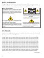
IPN430MC
Installation
Manual
TM
POWER
IPN430MC
LINK
HD
RECORD
MENU
OK
Notice for Installers
The servicing instructions in this notice are for use by qualified service personnel
only. To reduce the risk of electric shock, do not perform any servicing other than that
contained in the operating instructions, unless you are qualified to do so.
Note to System Installer
For this apparatus, the coaxial cable shield/screen shall be
grounded as close as practical to the point of entry of the cable
into the building.For products sold in the US and Canada, this
reminder is provided to call the system installer's attention to
Article 800-93 and Article 800-100 of the NEC (or Canadian
Electrical Code Part 1), which provides guidelines for proper
grounding of the coaxial cable shield.
CAUTION: To reduce the risk of electric shock, do not
remove cover (or back). No user-serviceable parts
inside. Refer servicing to qualified service personnel.
WARNING
TO PREVENT FIRE OR ELECTRIC SHOCK, DO NOT
EXPOSE THIS UNIT TO RAIN OR MOISTURE.
This symbol is intended to alert you that uninsulated voltage
within this product may have sufficient magnitude to cause
electric shock.Therefore, it is dangerous to make any kind of
contact with any inside part of this product.
Ce symbole a pour but d’alerter toute personne qu’un contact
avec une pièce interne de ce produit, sous tension et non isolée,
pourrait être suffisant pour provoquer un choc électrique. Il est
donc dangereux d’être en contact avec toute pièce interne de
ce produit.
This symbol is intended to alert you of the presence
of important operating and maintenance (servicing)
instructions in the literature accompanying this product.
Ce symbole a pour but de vous avertir qu’une
documentation importante sur le fonctionnement et
l’entretien accompagne ce produit.
20070131 SysInstaller 800 US/Canada/Intl
U.S. Patents
A patent notice is affixed to this product. In addition, the product may also be covered
by one or more of the following patents:
4,498,169, 4,692,919, 4,748,667; 4,829,569; 4,866,770; 4,885,775; 4,888,799; 4,890,319; 4,922,456; 4,922,532; 4,924,498;
4,965,534; 4,991,011; 5,003,384; 5,012,510; 5,029,207; 5,045,816; 5,053,883; 5,054,071; 5,058,160; 5,142,575; 5,142,690;
5,146,526; 5,155,590; 5,214,390; 5,225,902; 5,225,925; 5,235,619; 5,237,610; 5,239,540; 5,241,610; 5,247,364; 5,255,086;
5,257,403; 5,267,071; 5,270,809; 5,271,041; 5,272,752; 5,282,028; 5,285,497; 5,287,351; 5,301,028; 5,309,514; 5,317,391;
5,319,709; 5,341,425; 5,347,388; 5,347,389; 5,357,276; 5,359,601; 5,361,156; 5,367,571; 5,379,141; 5,379,145; 5,381,481;
5,390,337; 5,400,401; 5,406,558; 5,418,782; 5,420,866; 5,420,923; 5,425,101; 5,428,404; 5,430,568; 5,434,610; 5,436,749;
5,438,370; 5,440,632; 5,442,472; 5,455,570; 5,457,701; 5,471,492; 5,477,199; 5,477,262; 5,477,282 5,477,370; 5,481,389;
5,481,542; 5,485,221; 5,493,339; 5,497,187; 5,500,758; 5,502,499; 5,506,904; 5,519,780; 5,539,822; 5,550,825; 5,579,055;
5,579,057; 5,583,562; 5,592,551; 5,596,606; 5,600,378; 5,602,933; 5,640,388; 5,657,414; 5,675,575; 5,684,876; 5,715,515;
5,724,525; 5,734,822; 5,740,300; 5,742,677; 5,754,940; 5,757,416; 5,771,064; 5,774,859; 5,825,829; 5,826,167; 5,850,305;
5,854,703; 5,870,474; 5,892,607; 5,920,626; 5,923,755; 5,930,024; 5,930,515; 5,937,067; 5,963,352; 5,966,163; 5,982,424;
5,991,139; 5,999,207; 6,005,631; 6,005,938; 6,016,163; 6,028,941; 6,029,046; 6,052,384; 6,055,244; 6,072,532; 6,105,134;
6,148,039; 6,157,719; 6,188,729; 6,195,389; 6,212,278; 6,215,530; 6,219,358; 6,240,103; 6,243,145; 6,246,767; 6,252,964;
6,272,226; 6,292,081; 6,292,568; 6,320,131; 6,374,275; 6,405,239; 6,411,602; 6,417,949; 6,424,714; 6,424,717; 6,433,906;
6,438,139; 6,463,586; 6,467,091; 6,476,878; 6,493,876; 6,510,519; 6,516,002; 6,516,412; 6,526,508; 6,538,595; 6,546,013;
6,560,340; 6,567,118; 6,570,888; 6,622,308; 6,629,227; 6,664,984; 6,667,994; 6,671,879; 6,674,967; 6,678,891; 6,714,598;
6,721,352; 6,721,956; 6,725,459; 6,738,982; 6,744,892; 6,744,967; 6,751,271; 6,760,918; 6,795,972; 6,802,077; 6,804,708;
6,811,447; 6,817,028; 6,822,972; 6,823,385; 6,832,386; 6,845,106; 6,868,473; 6,874,075; 6,889,191; 6,909,471; 6,917,622;
6,917,628; 6,922,412; 6,927,806; 6,928,656; 6,931,058; 6,937,729; 6,969,279; 6,971,008; 6,971,121; 6,978,310; 6,986,156;
6,988,900; 6,996,838; 7,010,801; 7,053,960; 7,065,213; 7,069,578; 7,069572; D348065; D354959; D359737; D363932;
D390217; D434753; D507240; D507535; D513407; D516518; RE36368; RE36988
20070417 Patents
2
Contents
Important Safety Instructions ........................................................................................ 4
Change the Way You Watch TV ................................................................................... 6
Safety First ................................................................................................................... 6
Identifying Your IPN Device .......................................................................................... 6
In This Manual .............................................................................................................. 6
What’s on the Front Panel? .......................................................................................... 7
What’s on the Back Panel? .......................................................................................... 8
Connecting Your IPN Device ........................................................................................ 9
Connecting to the Home Network............................................................................... 10
Connections for an HDTV........................................................................................... 11
Connections for an SDTV ........................................................................................... 12
Connections for a VCR ............................................................................................... 12
Connecting to an HDTV with an HDMI Connector ..................................................... 13
Connecting to an HDTV with a DVI Connector........................................................... 14
Connecting to an HDTV with Component (PrPbY) Connectors ................................. 15
Connecting to a Home Theater System with Component (PrPbY) Connectors ......... 16
Connecting to a Stereo VCR (optional) ...................................................................... 17
Connecting to an SDTV with Component (PrPbY) Connectors.................................. 18
Connecting to an SDTV with an RCA-Type Connector .............................................. 19
Connecting to an SDTV with a Coaxial Cable ............................................................ 20
Viewing and Recording Television Programming ....................................................... 21
Troubleshooting .......................................................................................................... 21
Avoiding Screen Burn-In............................................................................................. 22
Frequently Asked Questions About HDTV.................................................................. 22
Picture Formats .......................................................................................................... 23
Index ........................................................................................................................... 25
Compliance Information.............................................................................................. 27
3
IMPORTANT SAFETY INSTRUCTIONS
Read These Instructions
Keep These Instructions
Heed All Warnings
Follow All Instructions
Power Source Warning
A label on this product indicates the
correct power source for this product.
Operate this product only from an
electrical outlet with the voltage and
frequency indicated on the product label.
If you are uncertain of the type of power
supply to your home or business, consult
your service provider or your local power
company.
Ground the Product
WARNING:
Avoid electric shock and fire hazard!
Do not defeat the safety purpose
of the polarized or grounding-type
plug. A polarized plug has two
blades with one wider than the
other. A grounding-type plug has
two blades and a third grounding
prong. The wide blade or the third
prong is provided for your safety. If
the provided plug does not fit into
your outlet, consult an electrician
for replacement of the obsolete
outlet.
If this product connects to coaxial cable
wiring, be sure the cable system is
grounded (earthed). Grounding provides
some protection against voltage surges
and built-up static charges.
Protect the Product from Lightning
For added protection, unplug this
apparatus during lightning storms or
when unused for long periods of time. In
addition to disconnecting the AC power
from the wall outlet, disconnect the signal
inputs.
4
Verify the Power Source from the
On/Off Power Light
When the on/off power light is not
illuminated, the apparatus may still be
connected to the power source. The
light goes out when the apparatus is
turned off, regardless of whether it is still
plugged into an AC power source.
Eliminate AC Mains Overloads
WARNING:
Avoid electric shock and fire
hazard! Do not overload AC
mains, outlets, extension cords, or
integral convenience receptacles.
For products that require battery
power or other power sources to
operate them, refer to the operating
instructions for those products.
Prevent Power Cord Damage
Protect the power cord from being walked
on or pinched, particularly at plugs,
convenience receptacles, and the point
where the cord exits from the apparatus.
Provide Ventilation and Select a
Location
• Do not block any ventilation openings.
Install in accordance with the
manufacturer’s instructions.
• Do not place this apparatus on a bed,
sofa, rug, or similar surface.
• Do not place this apparatus on an
unstable surface.
• Do not install near any heat sources
such as radiators, heat registers,
stoves, or other apparatus (including
amplifiers) that produce heat.
• Do not install this apparatus in an
enclosure, such as a bookcase or rack,
unless the installation provides proper
ventilation.
• Do not place entertainment devices
(such as VCRs or DVDs), lamps,
books, vases with liquids, or other
objects on top of this product.
IMPORTANT SAFETY INSTRUCTIONS, continued
Protect from Exposure to Moisture
and Foreign Objects
Do not use this apparatus near water.
WARNING:
Avoid electric shock and fire hazard!
Do not expose this product to
liquids, rain, or moisture.
WARNING:
Avoid electric shock and fire hazard!
Unplug this product before cleaning.
Clean only with a dry cloth. Do not
use a liquid cleaner or an aerosol
cleaner. Do not use a magnetic/static
cleaning device (dust remover) to
clean this product.
Service Warnings
WARNING:
Avoid electric shock! Do not open
the cover of this product. Opening
or removing the cover may expose
you to dangerous voltages. If you
open the cover, your warranty will be
void. This product contains no userserviceable parts. Refer all servicing
to qualified service personnel.
Servicing is required when the apparatus
has been damaged in any way, such as
a power-supply cord or plug is damaged,
liquid has been spilled or objects have
fallen into the apparatus, the apparatus has
been exposed to rain or moisture, does not
operate normally, or has been dropped.
Check Product Safety
WARNING:
Avoid electric shock and fire hazard!
Never push objects through the
openings in this product. Foreign
objects can cause electrical shorts
that can result in electric shock or
fire.
Accessories Warning
WARNING:
Avoid electric shock and fire hazard!
Only use attachments/accessories
specified by your service provider or
the manufacturer.
Upon completion of any service or
repairs to this product, the service
technician must perform safety checks to
determine that this product is in proper
operating condition.
Protect the Product when Moving It
Always disconnect the power source
when moving the apparatus or
connecting or disconnecting cables.
WARNING:
Avoid personal injury and
damage to this product!
Use only with the cart,
stand, tripod, bracket, or
table specified by the manufacturer or
sold with the apparatus. When a cart
is used, use caution when moving the
cart / apparatus combination to avoid
injury from tip-over.
20070320 Set-Top IP w/out DVB w/out Battery
5
Change the Way You Watch TV
Welcome to Internet Protocol Television (IPTV). The IPN430MC™ device (IPN
device), brings a rich, new set of services directly to you through your TV and your inhome IP network. The IPN device uses your existing in-home coaxial cable wiring and
connects to most all entertainment devices.
Available services may include some or all of the following features:
• Digital Video Recorder (DVR), which allows you to record your favorite programs
so that you can still go to your friend’s house for dinner and not miss your favorite
TV show.
• Pause Live TV, which allows you to pay for the pizza and come back to your show
where you left it.
• High-Definition (HD), which provides crystal clear pictures and sound when
compared to standard-definition – you won’t want to watch television any other way
once you’ve experienced HD.
• Video-On-Demand (VOD), which gives you access to an enormous library of
movies and shows that you can watch – when you want to watch them.
Note: Your IPN device may not support all of the above services. Contact your service
provider to find out if the DVR, HD, or VOD services are available and to activate the
services.
Follow the instructions in this guide to install the IPN device, to become familiar with
the buttons on the front panel, and to access your programming services. Then, enjoy
the features of the IPN device and change the way you watch TV!
Safety First
Before using the IPN device, read the Important Safety Instructions section of this
guide.
Identifying Your IPN Device
At times, your service provider may ask for the serial number. To find the serial
number for your IPN device, look on the bottom for a label. The serial number is a 9digit numeric code to the right of the letters “SN” on the label.
Use the space provided here to record the serial number:
____________________________________________
In This Manual
This manual provides the information you need to connect your IPN device to your
in-home network and to your entertainment devices. If you are new to the world of
high-definition TV (HDTV), we provide detailed information on HDTV, picture formats,
and troubleshooting at the end of this manual.
6
What’s on the Front Panel?
POWER
LINK
HD
RECORD
MENU
OK
IPN430MC
1
2
3
4
5
6
7
8
9
T12909
1 Power
Turns the IPN device on or places it in standby. The LED is green
2 Link
Indicates network link status. The LED is green
3 HD
Indicates that a high-definition program is in progress. The LED is blue
4 Record
Indicates that a recording is in process. The LED is red
5 IR Sensor
Receives the infrared signal from the remote control. The sensor is
behind the front panel
6 Menu
Accesses the on-screen menu
7 Arrow Keys Accesses on-screen services (such as the on-screen guide,
video-on-demand, or pay-per-view) and navigates menus
8 OK
Selects the current item
9 USB Port
Connects to external USB equipment approved by your service
provider
CAUTION:
Avoid damage to the product!
Your IPN device contains a sophisticated hard disk drive that is
designed to record and stream digital video. You must not mishandle this
DVR product. Handle this product with the same level of care you would
use when handling other electronics containing a hard disk drive, such
as computers.
Always wait at least 10 seconds after powering down the IPN device for
the DVR hard drive heads to spin down (stop) before moving or
handling the DVR.
7
What’s on the Back Panel?
TO WALL
(VIDEO IN)
1
NETWORK
2
USB
3
Pb
4
5
TO TV
(VIDEO OUT)
Y
S-VIDEO
VIDEO
OUT
AUDIO
OUT
OPTICAL
6
7
8
9
POWER
10
11
T12910
1 To Wall
(Video In)
Connect the IPN device to in-house coax wiring, if applicable. This
connection is used to receive an Ethernet-over-coaxial signal.
2 Network
Connect to the Ethernet (CAT-5) network in your home, if applicable
3 USB Port
Connect external USB equipment approved by your service
provider to this port
4 HDMI
Connect an HDTV HDMI™ (High-Definition Multimedia Interface)
cable from the HDTV to the HDMI port. HDMI supports both digital
audio and video. See page 11 for more information
5 PrPbY
Connect the IPN device to the component video input (PrPbY) on
the HDTV. See page 11 or page 12 for complete details
6 S-Video
Connect an S-Video cable to send an S-Video signal to your
TV or VCR. This signal is standard definition but higher quality than
other SDTV connections. See page 12 for more information
7 Video Out
Connect to either a VCR for archiving saved content from the IPN
device or connect to another set of inputs (composite) on your
HDTV or SDTV
8 Audio Out
(L/R)
Connect RCA-type cables to Audio Out to send analog audio
signals (left and right) to a TV with stereo inputs or to a stereo
amplifier
9 Optical
Connect an optical cable to send a digital audio signal to a
surround-sound receiver or other digital audio device
10 To TV
Connect to TV. This is a channel 3/4 output. You must set the
(Video Out) channel on your TV to the correct channel (either channel 3 or 4)
11 Power
8
Connect the DC output of the AC power adapter (provided) to
deliver power to the IPN device
Connecting Your IPN Device
To connect your IPP device to your in-home network and home entertainment devices,
complete these steps.
1
Determine if your TV is
16
HD or SD and whether it
9
is wide screen (16:9) or
standard screen (4:3). Refer
to the user’s guide that
came with your TV for more
information. See page 23 for more information.
4
or
3
Make one of the following connections to your home network:
2
• If your home has coaxial cable, use the TO WALL connector on the
IPN device. See page 10.
• If your home has twisted pair cable, use the TO WALL connector on
the IPN device and a balun (an adaptor that converts twisted pair to
coax). See page 10.
• If your home has CAT-5 cable, use the NETWORK connector on the
IPN device. See page 10.
Make the connections for your TV and/or VCR as follows:
3
• If you are using an HDTV, see page 11 and the connection diagrams
in this guide.
• If you are using an SDTV, see page 12 and the connection diagrams
in this guide.
• If you want to archive some programs to VCR tape, see page 12 and
the connection diagrams in this guide.
4
Identify the additional devices
you will connect to the IPN
device and TV. See pages 13
through 20 and the related
user’s guides for more
information.
VCR
DVD
Other
Home Theater
Plug the IPN device and the TV into an AC power source that is not
controlled by a switch. Do not turn on the IPN device or TV yet.
5
Do not turn on the IPN device or TV yet.
POWER For further instructions on completing your setup, refer to the IPN device
6
user’s guide from your service provider.
9
Connecting to the Home Network
The following diagrams illustrate examples of the connections you can use to connect
your IPN device to your in-home network. Contact your service provider for the
recommended connection method for your home.
Coaxial
TO WALL
(VIDEO IN)
NETWORK
Twisted Pair
USB
TO WALL
(VIDEO IN)
NETWORK
CAT-5
USB
OR
TO WALL
(VIDEO IN)
NETWORK
USB
OR
Balun
Wall
Wall
Wall
In-Home
Coaxial
Network
In-Home
Twisted Pair
Network
In-Home
CAT-5
Network
T12935
10
Connections for an HDTV
To use the IPN device with an HDTV, you must make one of the following connections
to view the HD content. Refer to your TV user’s guide and the cabling diagrams in this
guide for more detailed connection information.
Note: The labeling on your IPN device may vary slightly.
DVI
HDMI
Required Connections to an HDTV (use one)
The HDMI connector can provide the connection
to an HDTV with a DVI input. If your HDTV has a
Digital Visual Interface (DVI) connector, you will
need an HDMI-to-DVI adaptor, and you will need
to connect a separate audio connection.
Note: The DVI port on the TV must support highbandwidth digital content protection (HDCP).
The PrPbY connectors can provide high-definition
component video signals to an HDTV.
PrPbY
HDTV
Connections
Some HDTVs have an HDMI connector. The
HDMI connector provides both a digital video and
audio connection. See the connection diagram on
page 13 for an example.
See the connection diagram on page 14 for an
example.
Note: Set the HD mode and select the output
video format (480i, 480p, 720p, 1080i) on the IPN
device that matches the full capabilities of your
HDTV.
See the connection diagram on page 15 for an
example.
RGB
IPN Device
Connections
Some HDTVs have only RGB or RGB-HV
connectors. If you have one of these HDTVs, you
need an RGB adaptor. Check with your service
provider for information about acquiring an RGB
adaptor, or you can purchase the adaptor at your
local electronics supplier.
DVI
AUDIO
OUT
L
L
R
R
Adaptor Needed
Pr
Y
Pb
Y
Pr
Pb
AUDIO
OUT
L
R
Pr
R
Y
G
H
B
V
Pb
AUDIO
OUT
L
R
L
R
Adaptor Needed
11
Connections for an SDTV
When using the IPN device with an SDTV, you must make one of the following
connections to view content. Some SDTVs may not have all these connections. Refer to
your TV user’s guides and the cabling diagrams in this guide for more detailed information.
Note: The labeling on your IPN device may vary slightly.
PrPbY
Required Connections to an SDTV (use one)
The PrPbY (red, blue, and green) connectors can
provide standard-definition component video signals
to an SDTV.
Note: To connect PrPbY to an SDTV, you must set the
IPN device to an output video format that matches the
capabilities of your HDTV (typically only 480i).
S-Video
See the connection diagram on page 18 for an example.
The S-Video Out connection provides an optimal
video connection to SDTVs. A separate audio
connection is also needed.
SDTV
IPN Device
Connections Connections
Pr
Y
Pb
Pr
Y
Pb
AUDIO
OUT
L
R
Video Out
R
S-VIDEO
S-VIDEO
IN
AUDIO
OUT
L
The Video Out connector provides a video
connection to an SDTV. A separate audio connection
is also needed.
R
L
R
VIDEO
OUT
VIDEO
IN
AUDIO
OUT
L
To TV (Video Out)
L
The To TV (Video Out) connector provides a video
and audio connection to an SDTV. You must set the
channel on your TV to either channel 3 or channel 4.
R
L
R
TO TV
(VIDEO OUT)
CABLE IN/
ANT IN
Connections for a VCR
Optional Connection to a VCR (use one)
IPN Device
VCR
Connections Connections
VIDEO
OUT
VCR
For VCRs with Video and Left and Right audio
connectors, you can use the Video Out and the Audio
Out connectors (Left and Right) on the IPN device.
VIDEO
IN
See the connection diagram on page 17 for an
example.
AUDIO
OUT
L
For VCRs with S-Video and Left and Right audio
connectors, you can use the S-Video Out and the
Audio Out Left and Right connectors on the IPN
device.
L
R
S-VIDEO
IN
AUDIO
OUT
L
12
R
S-VIDEO
R
L
R
Connecting to an HDTV with an HDMI Connector
Cable Used in this Configuration
• 1 HDMI-to-HDMI Cable
WARNING:
Electric shock hazard! Unplug all electronic devices before connecting or
disconnecting any device cables to the IPN device.
IPN430MC
VIDEO
OUT
Pr
TO WALL
(VIDEO IN)
NETWORK
AUDIO
OUT
S-VIDEO
USB
OPTICAL
Y
L
Pb
TO TV
(VIDEO OUT)
POWER
R
Back of HDTV
AUDIO
CENTER
CHANNEL IN
ON
HDMI
OFF
AUDIO IN
DVI/HDCP
S-VIDEO
R
L
ANT (75 )
VIDEO
Y
VIDEO
L/
MONO
AUDIO
PB
L
PR
AUDIO
Y
L/
MONO
PB
L
R
PR
AUDIO
ANT-1
OUT
R
R
R
HD 2
HD 1
IN
IN
OUT
IN
ANT-2
T12912
13
Connecting to an HDTV with a DVI Connector
Cable Used in this Configuration
• 1 HDMI-to-DVI Cable or 1 HDMI-to-HDMI Cable and 1 HDMI-to-DVI Adaptor
• 1 Set Audio Left/Right Cables
Notes:
• The DVI port on the TV must support high-bandwidth digital content protection
(HDCP).
• When you connect the HDMI connector to the DVI connector on your HDTV, you
need an HDMI-to-DVI adaptor, and you need a separate audio connection.
WARNING:
Electric shock hazard! Unplug all electronic devices before connecting or
disconnecting any device cables to the IPN device.
IPN430MC
VIDEO
OUT
Pr
TO WALL
(VIDEO IN)
NETWORK
AUDIO
OUT
S-VIDEO
USB
OPTICAL
Y
Pb
L
TO TV
(VIDEO OUT)
POWER
R
Back of HDTV
AUDIO
CENTER
CHANNEL IN
ON
DVI/HDCP
IN
OFF
AUDIO IN
DVI/HDCP
S-VIDEO
R
L
ANT (75 )
VIDEO
Y
VIDEO
L/
MONO
AUDIO
PB
L
PR
AUDIO
Y
L/
MONO
PB
L
R
PR
AUDIO
ANT-1
OUT
R
R
R
HD 2
HD 1
IN
IN
OUT
IN
ANT-2
T12913
14
Connecting to an HDTV with Component (PrPbY)
Connectors
Cables Used in this Configuration
• 1 Set Component Video Cables (PrPbY)
• 1 Set Audio Left/Right Cables
WARNING:
Electric shock hazard! Unplug all electronic devices before connecting or
disconnecting any device cables to the IPN device.
IPN430MC
VIDEO
OUT
Pr
TO WALL
(VIDEO IN)
NETWORK
AUDIO
OUT
S-VIDEO
USB
OPTICAL
Y
L
Pb
Back of
HDTV
AUDIO
CENTER
CHANNEL IN
ON
TO TV
(VIDEO OUT)
POWER
R
HDMI
OFF
AUDIO IN
DVI/HDCP
S-VIDEO
R
L
ANT (75 )
VIDEO
Y
VIDEO
L/
MONO
AUDIO
PB
L
PR
AUDIO
Y
L/
MONO
PB
L
R
PR
AUDIO
ANT-1
OUT
R
R
R
HD 2
HD 1
IN
IN
OUT
IN
ANT-2
T12914
15
Connecting to a Home Theater System with
Component (PrPbY) Connectors
Cables Used in this Configuration
• 3 Sets Component Video Cables (PrPbY)
• 3 Sets Audio Left/Right Cables (you can also use optical cables instead of the
Audio Left/Right Cables as shown in the diagram, indicated by dotted lines)
• 1 RCA-type Video Cable
Note: This connection assumes that audio is provided by the home theater system.
IPN430MC
VIDEO
OUT
Pr
TO WALL
(VIDEO IN)
AUDIO
OUT
S-VIDEO
USB
NETWORK
TO TV
(VIDEO OUT)
OPTICAL
Y
L
Pb
POWER
R
OR
Back of Home
Theater Receiver
WARNING:
DIGITAL
AUDIO
Electric shock hazard! Unplug
all electronic devices before
connecting or disconnecting
any device cables to the IPN
device.
TV/CABLE
TV/CABLE
DVD
VIDEO 1
VIDEO 1
COMPONENT VIDEO
Y
Y
Y
PB
PB
PB
PR
PR
PR
MONITOR
S-VIDEO
S-VIDEO
S-VIDEO
S-VIDEO
VIDEO
VIDEO
VIDEO
VIDEO
S-VIDEO
OUT
2
3
L
L
L
L
AUDIO
AUDIO
AUDIO
AUDIO
R
R
1
4
Back of Home Theater Receiver
DIGITAL
AUDIO
DVD
1
COMPONENT VIDEO
Y
Y
MONITOR
IN
R
OUT
IN
2
VIDEO OUT
OUT
R
Back of Home Theater Receiver
DIGITAL
AUDIO
TV/CABLE
DVD
S-VIDEO
S-VIDEO
S-VIDEO
VIDEO 1
S-VIDEO
VIDEO
VIDEO
VIDEO
VIDEO
COMPONENT VIDEO
Y
Y
Y
Y
PB
PB
PB
PR
PR
PR
MONITOR
1
1
S-VIDEO
S-VIDEO
S-VIDEO
S-VIDEO
VIDEO
VIDEO
VIDEO
VIDEO
PB
PB
PB
PR
PR
PR
S-VIDEO
OUT
2
L
L
L
L
L
AUDIO
AUDIO
AUDIO
AUDIO
AUDIO
R
R
R
L
L
1
4
AUDIO
AUDIO
R
R
AUDIO
IN
R
OUT
2
IN
OUT
VIDEO OUT
1
IN
4
Back of
HDTV
IN
R
OR
AUDIO
CENTER
CHANNEL IN
S-VIDEO
OUT
3
3
L
2
OUT
2
OUT
VIDEO OUT
R
Back
of DVD
Player
HDMI
SCART VIDEO IN
ON
DIGITAL
OUT
COAXIAL
OFF
AUDIO OUT
R
L
Y
PB
VIDEO
OUT
AUDIO IN
DVI/HDCP
SCART VIDEO OUT
S-VIDEO
R
L
ANT (75 )
VIDEO
Y
VIDEO
L/
MONO
AUDIO
PB
L
PR
AUDIO
L/
MONO
R
OPTICAL
DIGITAL OUT
Y
PB
L
PR
AUDIO
S-VIDEO
OUT
PR
COMPONENT VIDEO OUT/
PROGRESSIVE SCAN
ANT-1
OUT
R
R
VIDEO-1
IN
16
R
HD 1
HD 2
IN
OUT
IN
ANT-2
T12915
Connecting to a Stereo VCR (optional)
Cables Used in this Configuration
• 2 RCA-type Video Cables
• 2 Sets Audio Left/Right Cables
Note: This connection does not provide an HD signal to the TV. You must use one of
the video connections shown on pages 13-15 or page 18 in addition to this connection
to obtain an HD signal to the TV.
WARNING:
Electric shock hazard! Unplug all electronic devices before connecting or
disconnecting any device cables to the IPN device.
IPN430MC
VIDEO
OUT
Pr
TO WALL
(VIDEO IN)
NETWORK
AUDIO
OUT
S-VIDEO
USB
OPTICAL
Y
Back of
Stereo VCR
Pb
L
TO TV
(VIDEO OUT)
POWER
R
RF IN
L
VIDEO
IN
R
L
AUDIO
IN
VIDEO
OUT
R
RF OUT
AUDIO
OUT
Back of
HDTV
AUDIO
CENTER
CHANNEL IN
ON
DVI/HDCP
IN
OFF
AUDIO IN
DVI/HDCP
Connecting your TV
directly to the Audio/
Video output of your
set-top will assure a
more vivid picture and
enhance your viewing
enjoyment.
S-VIDEO
R
L
ANT (75½)
VIDEO
Y
VIDEO
L/
MONO
AUDIO
PB
L
PR
AUDIO
Y
L/
MONO
PB
L
R
PR
AUDIO
ANT-1
OUT
R
R
VIDEO-1 VIDEO-2 HD 1
IN
R
AUDIO
IN
OUT
HD 2
IN
ANT-2
T12916
17
Connecting to an SDTV with Component (PrPbY)
Connectors
Cables Used in this Configuration
• 1 Component Video Cable (PrPbY)
• 1 Set Audio Left/Right Cables
Note: The IPN device must be set to the proper output mode, typically 480i or 480p.
WARNING:
Electric shock hazard! Unplug all electronic devices before connecting or
disconnecting any device cables to the IPN device.
IPN430MC
VIDEO
OUT
Pr
TO WALL
(VIDEO IN)
NETWORK
AUDIO
OUT
S-VIDEO
USB
OPTICAL
Y
L
Pb
TO TV
(VIDEO OUT)
POWER
R
Back of SDTV
RF IN
Y
L
PB
PR
VIDEO
IN
R
AUDIO
IN
L
VIDEO
OUT
R
AUDIO
OUT
RF OUT
T12917
18
Connecting to an SDTV with an RCA-Type Connector
Cables Used in this Configuration
• 1 RCA-type Video Cable
• 1 Set Audio Left/Right Cables
WARNING:
Electric shock hazard! Unplug all electronic devices before connecting or
disconnecting any device cables to the IPN device.
IPN430MC
VIDEO
OUT
Pr
TO WALL
(VIDEO IN)
NETWORK
AUDIO
OUT
S-VIDEO
USB
OPTICAL
Y
Pb
Back of
SDTV
L
LEFT
OUT IN
TO TV
(VIDEO OUT)
POWER
R
VIDEO
OUT
IN
CABLE/
ANTENNA
AUDIO
OUT IN
RIGHT
T12918
19
Connecting to an SDTV with a Coaxial Cable
Cables Used in this Configuration
• 1 RCA-type Video Cable
• 1 Set Audio Left/Right Cables
Note: You must set the channel on your TV to the correct channel (either channel 3 or
channel 4). Contact your service provider for the channel information.
WARNING:
Electric shock hazard! Unplug all electronic devices before connecting or
disconnecting any device cables to the IPN device.
IPN430MC
VIDEO
OUT
Pr
TO WALL
(VIDEO IN)
NETWORK
AUDIO
OUT
S-VIDEO
USB
OPTICAL
Y
Back of
SDTV
L
Pb
LEFT
OUT IN
VIDEO
OUT
IN
TO TV
(VIDEO OUT)
POWER
R
CABLE/
ANTENNA
AUDIO
OUT IN
RIGHT
20
T12919
Viewing and Recording Television Programming
Access Services and Programs
Access programming services and programs by pressing the following keys on the
remote control:
• Guide – Access the on-screen program guide. The on-screen guide displays
schedules of TV programs and other services available from your service provider,
such as video-on-demand and pay-per-view programs.
• Arrows – Move through the Program Guide or Menu.
• Info – Display a specific program description (either from the on-screen guide or
while viewing a program).
• OK – View or select a highlighted choice in the Program Guide or Menu.
Troubleshooting
If the IPN device does not perform as expected, the following tips may help. If you
need further assistance, contact your service provider.
No Picture
• Verify that the power to your TV is turned on.
• If the IPN device is plugged into a wall switch, verify that the switch is in the ON
position.
• Verify that all cables are properly connected.
• If your system includes a VCR or stereo, verify that you have properly connected
them to the IPN device.
• Verify the proper input selection to the home theater receiver or TV.
• Verify that the IPN device is set to the proper screen type and resolution.
• If you are using coaxial cable to connect to your TV, verify that the TV is tuned to the
correct channel.
No Color or Incorrect Color
• Verify that the current TV program is broadcast in color.
• Adjust the TV color controls.
• If you are using a component video connection (PrPbY), check that all connectors
are completely and properly plugged into the IPN device and TV.
• If you are using a component video connection (PrPbY) and your HDTV only has
RGB or RGB-HV connectors, you must use an adapter. Contact your service
provider for more information.
21
No Sound
• If your setup includes a VCR or stereo, verify that you have properly connected
them to the IPN device.
• Verify that the volume is turned up.
• Verify that the mute function is not on.
• Verify the proper input selection to the home theater receiver or TV.
• If you are using coaxial cable to connect to your TV, verify that the TV is tuned to the
correct channel.
Avoiding Screen Burn-In
Images such as letterbox bars or side bars, bright closed-captioning backgrounds, station
logos, or any other stationary images may cause the display in your HDTV to age
unevenly; this is known as screen burn-in. Refer to the user’s guide that came with
your HDTV for more information.
CAUTION:
Avoid screen burn-in! Do not display the same fixed images on your HDTV
screen for extended periods of time.
Frequently Asked Questions About HDTV
What Is Digital Television?
Digital television (DTV) is a huge leap forward in television technology compared to
analog television that has been widely available since the 1940s. DTV is delivered
and displayed using digital encoding, similar to the way a PC operates. By using
digital technology, there is no variation in picture and sound quality from the
origination point until it is displayed on your television. You always receive a highquality picture without the wavy lines or static you might sometimes get from a weak
analog signal. Another feature of digital television is digital surround sound using
Dolby® Digital, which is the same technology used to produce the sound you hear in
movie theaters.
What Is Standard-Definition Television?
Standard-definition television (SDTV) is basic digital television programming delivered
by your service provider. Typically, the SDTV screen is the same, nearly square
shape as an analog television screen. Digital images on an SDTV set are crisp and
clear—noticeably better than on a standard analog television set using an antenna to
receive over-the-air signals.
What Is High-Definition Television?
High-definition television (HDTV) is a completely new way to send and receive
television broadcast signals. HDTV images are made up of pixels that are much
smaller and closer together than those used in standard analog television, and there
are millions of them. Thus, HDTV can display five to six times the detail of analog
television to deliver picture quality that is much more realistic, dimensional, and
precise. SDTV programs can be viewed on an HDTV.
22
Are Local TV Stations or Other Programmers Broadcasting in HDTV?
Many local TV stations and programmers are transmitting digital signals. However,
transmitting a digital signal does not mean transmitting an HDTV signal. Some
stations are using the new bandwidth to broadcast several standard-definition
channels. Most stations and programmers, once they begin broadcasting in digital,
are offering HD content from their parent network (for example, CBS, ABC, NBC, Fox,
WB, UPN, and PBS). Contact your service provider for more information.
Why Aren’t All the Shows I Watch in High-Definition?
A high-definition program must originate in HD format and be broadcast in HD format.
Having an HDTV system does not mean that everything you watch will be viewed in
high-definition. Getting the signal from a digital source also does not mean it is highdefinition.
Why Are Some HDTVs 4:3 Aspect Ratio and Others 16:9?
The aspect ratios differ because television manufacturers build both standard-screen
and wide-screen HDTVs to appeal to consumer viewing preferences. The two aspect
ratios are as follows:
• On wide-screen (16:9) HDTVs, the programming is displayed on the full screen.
• On standard-screen (4:3) HDTVs, the programming is displayed in letterbox format
in the middle of the screen. There are bars surrounding the picture.
Picture Formats
What Is the Difference Between a Standard-Screen and a Wide-Screen
HDTV?
The type of screen your HDTV has (wide screen or standard screen) determines how
the IPN device displays programs on the screen. The picture format for an HDTV is a
combination of aspect ratio and screen resolution and is different for standard-screen
and wide-screen HDTVs.
What Is Aspect Ratio?
An aspect ratio is the ratio of the width to the height of the TV screen. The aspect
ratios differ because the television industry manufactures both standard-screen and
wide-screen HDTVs to appeal to consumer viewing preferences.
What Is the Screen Resolution and Scan Rate?
The screen resolution indicates the amount of detail that the picture displays.
Resolution is identified by the number of display lines on the screen. The techniques
that an HDTV uses to “paint” the picture on the screen are referred to as progressive
and interlaced.
With the progressive method, every pixel on the screen is refreshed simultaneously.
The interlace method involves refreshing pixels in alternation — first the odd lines
and then the even lines.
For advance setup, select the scan modes that your TV can support. Refer to your
DVR and HDTV user’s guides to choose the proper scan rates (480i, 480p, 720p,
1080i) for your setup.
23
For example, a resolution of 1080i indicates that the screen shows 1080 lines in
an interlaced display, and 480p indicates that the screens shows 480 lines in a
progressive display.
Note: The screen resolution (1080i, 480p, and so forth) is sometimes referred to as
the scan rate. The terms are interchangeable.
A standard-screen HDTV has a 4x3
aspect ratio. The screen is 4 units
wide for every 3 units tall.
A wide-screen HDTV is one-third wider than
a standard-screen HDTV. The screen is 16
units wide for every 9 units tall.
16
4
3
A screen resolution of 576p or 576i
fills the screen.
24
9
A screen resolution of 720p or 1080i fills the
screen.
Index
A
Controls. See Front panel
AC Power input
Arrow keys
8
D
7
Aspect ratio
Diagrams. See Connecting the IPN
device
to other devices
23, 24
Audio Out
8, 11, 12
Digital Video Recorder. See DVR, What
is it
B
Digital TV, What is it
Back panel
8
DVI connector
Burn-in of screen
22
22
11, 14
DVR, What is it
6
Buttons. See Front panel
E
C
Ethernet network
Cables
CAT-5
8, 9, 10
9, 10, 13-20
10
F
Coaxial Cable Input
8, 9, 10, 20
Coaxial network connection
Compliance, FCC
10
27
FAQs
22
FCC compliance
27
Formats, picture
23
Component video connection. See PrPbY
Frequently Asked Questions. See FAQs
Connectors
Front panel
7
See also Front panel; Back panel
required for HDTV
11
H
required for SDTV
12
Hard disk drive, caution
VCR
12, 17
HD
Connecting the IPN device to other
devices
format
DVI connector
indicator
17
13
Home Theater System with
Component input (PrPbY) 15
SDTV
HDMI
23
22
7
8, 11, 13, 14
High-definition. See HD
Home theater system connection
16
12, 18, 19, 20
S-Video
VCR
HDTV, What is it
14
HDMI connector
23
HDTV broadcasting
Component input (PrPbY) 15, 16
DVD
7
I
12
Interlaced scan rate
12, 17
IR sensor
Connection
23
7
Home Network 10
User Device
9
25
Index, continued
K
Serial number, locating
Keys. See Front panel
Sound, performance
6
22
Standard-definition TV, What is it
N
T
Network
9, 10
To Wall (Video In) connector
8, 10
To TV (Video Out) connector
O
Troubleshooting
Optical Audio Output
8, 16
21-22
digital, what is it
formats
Picture formats
23-24
22
9, 23
HDTV, what is it
22
Ports. See Connectors
programming
Power
recording
6, 22
resolution
23-24
7, 8
Programs, view
21, 22, 23
Progressive scan rate
23
23
screen size. See aspect ratio
PrPbY
standard screen
connector
8, 11, 12
SDTV connection
23-24
standard-definition, what is it
HDTV connection 11, 15, 16
home theater connection
wide screen
24
16
12, 18-20
U
USB port
7, 8
R
Record programs
RGB connector
6, 21
11
V
VCR connection
Video In
S
Video Out
S-Video
8, 12
S-Video In
Safety
Scan rates
See To TV
21-24
W
23-24
Watch TV
21
Widescreen TV
burn-in
24
22
resolution
23-24
23-24
9, 12, 22, 23
TV, What is it
Y
YPbPr. See PrPbY
SD
Mode
See To Wall
View programs
Screen
size
12, 17
12
2, 4-5
22
8, 12, 20
TV
P
26
23
22
Compliance Information
United States FCC Compliance
This device has been tested and found to comply
with the limits for a Class B digital device, pursuant
to part 15 of the FCC Rules. These limits are
designed to provide reasonable protection against
such interference in a residential installation. This
equipment generates, uses, and can radiate radio
frequency energy. If not installed and used in
accordance with the instructions, it may cause harmful
interference to radio communications. However, there
is no guarantee that interference will not occur in a
particular installation. If this equipment does cause
harmful interference to radio or television reception,
which can be determined by turning the equipment
OFF and ON, the user is encouraged to try
to correct the interference by one or more of the
following measures:
• Reorient or relocate the receiving antenna, if
applicable.
• Increase the separation between the equipment
and receiver.
• Connect the equipment into an outlet on a circuit
different from that to which the receiver is connected.
AVC Video License
THIS PRODUCT IS LICENSED UNDER THE
AVC PATENT PORTFOLIO LICENSE FOR THE
PERSONAL AND NON-COMMERCIAL USE
OF A CONSUMER TO (i) ENCODE VIDEO IN
COMPLIANCE WITH THE AVC STANDARD (“AVC
VIDEO”) AND/OR (ii) DECODE AVC VIDEO THAT
WAS ENCODED BY A CONSUMER ENGAGED
IN A PERSONAL AND NON-COMMERCIAL
ACTIVITY AND/OR WAS OBTAINED FROM A
VIDEO PROVIDER LICENSED TO PROVIDE AVC
VIDEO. NO LICENSE IS GRANTED OR SHALL
BE IMPLIED FOR ANY OTHER USE. ADDITIONAL
INFORMATION MAY BE OBTAINED FROM MPEG
LA, L.L.C. SEE http://www.mpegla.com.
Macrovision Copyright Notice
This product incorporates copyright protection
technology that is protected by U.S. patents
and other intellectual property rights. Use of this
copyright protection technology must be authorized
by Macrovision, and is intended for home and
other limited viewing uses only unless otherwise
authorized by Macrovision. Reverse engineering or
disassembly is prohibited.
Trademarks
• Consult the cable company or an experienced
radio/television technician for help.
Scientific Atlanta is a registered trademark of
Scientific-Atlanta, Inc.
Any changes or modifications not expressly
approved by Scientific-Atlanta, Inc., could void the
user’s authority to operate the equipment.
IPN430MC is a trademark of Scientific-Atlanta, Inc.
The information shown in the FCC Declaration of
Conformity paragraph below is a requirement of the
FCC and is intended to supply you with information
regarding the FCC approval of this device. The phone
numbers listed are for FCC-related questions only and
not intended for questions regarding the connection
or operation for this device. Please contact your cable
service provider for any questions you may have
regarding the operation or installation of this device.
FCC Declaration of Conformity
This device complies with Part 15 of FCC Rules.
Operation is subject to the following two conditions:
1) the device may not cause harmful interference, and
2) the device must accept any interference received,
including interference that may cause undesired
operation.
Model IPN430MC
Scientific-Atlanta, Inc.;
5030 Sugarloaf Parkway;
Lawrenceville, Georgia 30044; USA
Telephone 770-236-1077
Cisco, Cisco Systems, and the Cisco Systems logo
are registered trademarks of Cisco Systems, Inc.
and/or its affiliates in the U.S. and certain other
countries.
Manufactured under license from Dolby Laboratories.
“Dolby” and the double-D symbol are registered
trademarks of Dolby Laboratories.
HDMI, the HDMI logo, and High-Definition
Multimedia Interface are trademarks or registered
trademarks of HDMI Licensing LLC.
Macrovision is a registered trademark of Macrovision
Corp.
All other trademarks shown are trademarks of their
respective owners.
Disclaimer
Scientific-Atlanta, Inc. assumes no responsibility for
errors or omissions that may appear in this guide.
Scientific-Atlanta, Inc. reserves the right to change
this guide at any time without notice.
Canada EMI Regulation
This Class B digital apparatus complies with
Canadian ICES-003.
Cet appareil numérique de la class B est conforme à
la norme NMB-003 du Canada.
20060628FDC
27
Scientific Atlanta, A Cisco Company
5030 Sugarloaf Parkway
Box 465447
Lawrenceville, GA 30042
770.236.5000
www.scientificatlanta.com
This document includes various trademarks of Scientific-Atlanta, Inc. Please see
the Trademarks section of this document for a list of the Scientific-Atlanta, Inc.,
trademarks used in this document. All other trademarks shown are trademarks
of their respective owners.
Product and service availability is subject to change without notice.
© 2007 Scientific-Atlanta, Inc. All rights reserved.
April 2007
Printed in United States of America
4013801 Rev C