1
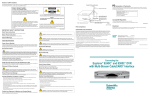
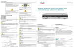
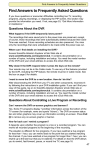
User Guide
Explorer 8300
Digital Video Recorder
CH +
GUIDE
POWER
INFO
EXIT
LIST
L AUDIO R
VIDEO
VOL -
VOL +
CH -
SELECT
Notice for Installers
The servicing instructions in this notice are for use by qualified service personnel
only. To reduce the risk of electric shock, do not perform any servicing other than that
contained in the operating instructions, unless you are qualified to do so.
Note to System Installer
For this apparatus, the coaxial cable shield/screen shall be
grounded as close as practical to the point of entry of the cable
into the building. For products sold in the US and Canada, this
reminder is provided to call the system installer's attention to
Article 820-93 and Article 820-100 of the NEC (or Canadian
Electrical Code Part 1), which provides guidelines for proper
grounding of the coaxial cable shield.
CAUTION: To reduce the risk of electric shock, do not
remove cover (or back). No user-serviceable parts
inside. Refer servicing to qualified service personnel.
WARNING
TO PREVENT FIRE OR ELECTRIC SHOCK, DO NOT
EXPOSE THIS UNIT TO RAIN OR MOISTURE.
This symbol is intended to alert you that uninsulated voltage
within this product may have sufficient magnitude to cause
electric shock.Therefore, it is dangerous to make any kind of
contact with any inside part of this product.
Ce symbole a pour but d’alerter toute personne qu’un contact
avec une pièce interne de ce produit, sous tension et non isolée,
pourrait être suffisant pour provoquer un choc électrique. Il est
donc dangereux d’être en contact avec toute pièce interne de
ce produit.
This symbol is intended to alert you of the presence
of important operating and maintenance (servicing)
instructions in the literature accompanying this product.
Ce symbole a pour but de vous avertir qu’une
documentation importante sur le fonctionnement et
l’entretien accompagne ce produit.
20070131 SysInstaller 820 US/Canada/Intl
U.S. Patents
A patent notice is affixed to this product. In addition, the product may also be covered
by one or more of the following patents:
4,498,169; 4,692,919; 4,748,667; 4,829,569; 4,866,770; 4,885,775; 4,888,799; 4,890,319; 4,922,456; 4,922,532; 4,924,498;
4,965,534; 4,991,011; 5,003,384; 5,012,510; 5,029,207; 5,045,816; 5,053,883; 5,054,071; 5,058,160; 5,142,575; 5,142,690;
5,146,526; 5,155,590; 5,214,390; 5,225,902; 5,225,925; 5,235,619; 5,237,610; 5,239,540; 5,241,610; 5,247,364; 5,255,086;
5,257,403; 5,267,071; 5,270,809; 5,271,041; 5,272,752; 5,282,028; 5,285,497; 5,287,351; 5,301,028; 5,309,514; 5,317,391;
5,319,709; 5,341,425; 5,347,388; 5,347,389; 5,357,276; 5,359,601; 5,361,156; 5,367,571; 5,379,141; 5,379,145; 5,381,481;
5,390,337; 5,400,401; 5,406,558; 5,418,782; 5,420,866; 5,420,923; 5,425,101; 5,428,404; 5,430,568; 5,434,610; 5,436,749;
5,438,370; 5,440,632; 5,442,472; 5,455,570; 5,457,701; 5,471,492; 5,477,199; 5,477,262; 5,477,282 5,477,370; 5,481,389;
5,481,542; 5,485,221; 5,493,339; 5,497,187; 5,500,758; 5,502,499; 5,506,904; 5,519,780; 5,539,822; 5,550,825; 5,579,055;
5,579,057; 5,583,562; 5,592,551; 5,596,606; 5,600,378; 5,602,933; 5,640,388; 5,657,414; 5,675,575; 5,684,876; 5,715,515;
5,724,525; 5,734,822; 5,740,300; 5,742,677; 5,754,940; 5,757,416; 5,771,064; 5,774,859; 5,825,829; 5,826,167; 5,850,305;
5,854,703; 5,870,474; 5,892,607; 5,920,626; 5,923,755; 5,930,024; 5,930,515; 5,937,067; 5,963,352; 5,966,163; 5,982,424;
5,991,139; 5,999,207; 6,005,631; 6,005,938; 6,016,163; 6,028,941; 6,029,046; 6,052,384; 6,055,244; 6,072,532; 6,105,134;
6,148,039; 6,157,719; 6,188,729; 6,195,389; 6,212,278; 6,215,530; 6,219,358; 6,240,103; 6,243,145; 6,246,767; 6,252,964;
6,272,226; 6,292,081; 6,292,568; 6,320,131; 6,374,275; 6,405,239; 6,411,602; 6,417,949; 6,424,714; 6,424,717; 6,433,906;
6,438,139; 6,463,586; 6,467,091; 6,476,878; 6,493,876; 6,510,519; 6,516,002; 6,516,412; 6,526,508; 6,538,595; 6,546,013;
6,560,340; 6,567,118; 6,570,888; 6,622,308; 6,629,227; 6,664,984; 6,667,994; 6,671,879; 6,674,967; 6,678,891; 6,714,598;
6,721,352; 6,721,956; 6,725,459; 6,738,982; 6,744,892; 6,744,967; 6,751,271; 6,760,918; 6,795,972; 6,802,077; 6,804,708;
6,811,447; 6,817,028; 6,822,972; 6,823,385; 6,832,386; 6,845,106; 6,868,473; 6,874,075; 6,889,191; 6,909,471; 6,917,622;
6,917,628; 6,922,412; 6,927,806; 6,928,656; 6,931,058; 6,937,729; 6,969,279; 6,971,008; 6,971,121; 6,978,310; 6,986,156;
6,988,900; 6,996,838; 7,010,801; 7,053,960; 7,065,213; 7,069,578; 7,069572; D348065; D354959; D359737; D363932;
D390217; D434753; D507240; D507535; D513407; D516518; RE36368; RE36988
20070417 Patents
Contents
IMPORTANT SAFETY INSTRUCTIONS ........................................................ iv
Change the Way You Watch TV ......................................................................1
Safety First ......................................................................................................1
Serial Number..................................................................................................1
Front Panel Features .......................................................................................2
Back Panel Connectors ...................................................................................3
Connecting the DVR ........................................................................................4
Connections for a Standard-Definition TV and VCR .......................................5
Watch TV .........................................................................................................6
Performance Tips ............................................................................................7
Frequently Asked Questions............................................................................7
Connecting to a Standard TV ..........................................................................8
Connecting to a Standard TV and Standard VCR ...........................................8
Connecting to a Stereo TV ..............................................................................9
Connecting to a Stereo TV and Stereo VCR ...................................................9
Connecting to a Home Theater Receiver and Stereo TV ..............................10
Connecting an External SATA Hard Disk Drive (optional) .............................11
FCC Compliance ...........................................................................................13
iii
IMPORTANT SAFETY INSTRUCTIONS
Read These Instructions
Keep These Instructions
Heed All Warnings
Follow All Instructions
Power Source Warning
A label on this product indicates the correct power source for
this product. Operate this product only from an electrical outlet
with the voltage and frequency indicated on the product label.
If you are uncertain of the type of power supply to your home
or business, consult your service provider or your local power
company.
The AC inlet on the unit must remain accessible and operable
at all times.
Ground the Product
WARNING: Avoid electric shock and
fire hazard! Do not defeat the safety purpose of
the polarized or grounding-type plug. A polarized
plug has two blades with one wider than the other.
A grounding-type plug has two blades and a third
grounding prong. The wide blade or the third prong
is provided for your safety. If the provided plug does
not fit into your outlet, consult an electrician for
replacement of the obsolete outlet.
T13508
Protect the Product from Lightning
For added protection, unplug this apparatus during lightning
storms or when unused for long periods of time. In addition to
disconnecting the AC power from the wall outlet, disconnect the
signal inputs.
Verify the Power Source from the
On/Off Power Light
When the on/off power light is not illuminated, the apparatus
may still be connected to the power source. The light may go
out when the apparatus is turned off, regardless of whether it is
still plugged into an AC power source.
Eliminate AC Mains Overloads
If this product connects to coaxial cable wiring, be sure the
cable system is grounded (earthed). Grounding provides some
protection against voltage surges and built-up static charges.
Outdoor Grounding System
If this product connects to an outdoor antenna or cable system,
be sure the antenna or cable system is grounded (earthed).
This provides some protection against voltage surges and
built-up static charges.
Article 810 of the National Electric Code (NEC) ANSI/NFPA No.
70-1990, provides the following information:
• Grounding of the mast and supporting structure
• Grounding the lead-in wire to an antenna discharge unit
WARNING: Avoid electric shock and fire
hazard! Do not overload AC mains, outlets, extension
cords, or integral convenience receptacles. For
products that require battery power or other power
sources to operate them, refer to the operating
instructions for those products.
Prevent Power Cord Damage
Protect the power cord from being walked on or pinched,
particularly at plugs, convenience receptacles, and the point
where the cord exits from the apparatus.
• Size of the grounding conductors
• Location of the antenna-discharge unit
• Connection to grounding electrodes
• Requirements for the grounding electrodes (see the
following antenna grounding diagram as recommended by
NEC ANSI/NFPA 70)
Provide Ventilation and Select a Location
• Remove all packaging material before applying power to the
product.
• Do not block any ventilation openings. Install in accordance
with the manufacturer’s instructions.
• Do not place this apparatus on a bed, sofa, rug, or similar
surface.
WARNING: Avoid electric shock and fire
hazard! Do not locate an outside antenna system in
the vicinity of overhead power lines or power circuits.
Touching power lines or circuits might be fatal.
• Do not place this apparatus on an unstable surface.
• Do not install near any heat sources such as radiators, heat
registers, stoves, or other apparatus (including amplifiers)
that produce heat.
• Do not install this apparatus in an enclosure, such as a
bookcase or rack, unless the installation provides proper
ventilation.
• Do not place entertainment devices (such as VCRs or
DVDs), lamps, books, vases with liquids, or other objects on
top of this product.
iv
IMPORTANT SAFETY INSTRUCTIONS, continued
Protect from Exposure to Moisture
and Foreign Objects
Do not use this apparatus near water.
WARNING: Avoid electric shock and fire
hazard! Do not expose this product to liquids, rain, or
moisture.
WARNING: Avoid electric shock and fire
hazard! Unplug this product before cleaning. Clean
only with a dry cloth. Do not use a liquid cleaner
or an aerosol cleaner. Do not use a magnetic/static
cleaning device (dust remover) to clean this product.
Protect the Product When Moving It
Always disconnect the power source when moving the
apparatus or connecting or disconnecting cables.
WARNING: Avoid personal injury and
damage to this product! Use only with
the cart, stand, tripod, bracket, or table
specified by the manufacturer or sold
with the apparatus. When a cart is used,
use caution when moving the cart /
apparatus combination to avoid injury
from tip-over.
20080402 Set-Top Cable US & Canada
WARNING: Avoid electric shock and fire
hazard! Never push objects through the openings
in this product. Foreign objects can cause electrical
shorts that can result in electric shock or fire.
Accessories Warning
WARNING: Avoid electric shock and fire
hazard! Only use attachments/accessories specified
by your service provider or the manufacturer.
Service Warnings
WARNING: Avoid electric shock! Do not
open the cover of this product. Opening or removing
the cover may expose you to dangerous voltages. If
you open the cover, your warranty will be void. This
product contains no user-serviceable parts. Refer all
servicing to qualified service personnel.
Servicing is required when the apparatus has been damaged
in any way, such as a power-supply cord or plug is damaged,
liquid has been spilled or objects have fallen into the apparatus,
the apparatus has been exposed to rain or moisture, does not
operate normally, or has been dropped.
Check Product Safety
Upon completion of any service or repairs to this product, the
service technician must perform safety checks to determine
that this product is in proper operating condition.
v
Change the Way You Watch TV
DVR makes it easy to watch TV on your terms.
The Cisco® Explorer® 8300 Digital Video Recorder (DVR) is the simple way to take
control over your TV – and your life. You take control because the DVR lets you
decide what’s on TV and when. So there’s no more putting off the things you need to
do, just because there’s a show on TV you want to watch. Just think what the DVR
can do for you:
• Never miss a minute of your favorite movie or the big game. Simply pause the live
action and play again when you’re ready. You can even rewind what you missed.
• Two of your favorite shows on at the same time? Simple. Just record one program
while you watch the other. You can also record two programs at the same time
while watching a previously recorded program. Your VCR can’t do that.
• Is your favorite sports team having an away game and you can’t go? Imagine
being able to record it and watch it at a more convenient time.
Don’t miss another minute of the TV shows you love!
Follow the instructions in this guide to install the DVR, to become familiar with the
buttons on the front panel, and to access your cable services. Then, enjoy the
features of the 8300 DVR and change the way you watch TV.
Safety First
Before using the DVR, read the Important Safety Instructions section of this guide.
Serial Number
If the DVR requires troubleshooting in the future, your service provider may ask for
the serial number.
To find the serial number for your DVR, look on the back panel for a label that is
similar to the example shown here. The serial number begins with “SA” and is located
in the lower left corner of the bar code.
Use the space provided here to record the serial number:
____________________________________________
0003B4287797
SABDQXTL
Serial Number
N0006246618
T11185
1
Front Panel Features
CH +
GUIDE
POWER
VOL -
INFO
VOL +
CH -
SELECT
EXIT
LIST
L AUDIO R
1
1 Power
2
VIDEO
3 4 5 6 7
8 9
10
11 12 13
T13467
Turns the DVR on and off
2 Video and
Connects to video and left/right (L/R) audio outputs of an external
Audio Input* device to deliver the audio and video to a TV or other device
3 List
Displays the list of recorded programs
4 Exit
Exits menus, the on-screen guide, and program information
5 Info
Displays a description of the selected program. This button is
available from the on-screen guide and while viewing a program
6 Guide
Accesses on-screen services, such as the on-screen guide,
video-on-demand, or pay-per-view
7 IR Sensor
Receives the infrared signal from the remote control
8 LED Display Displays the selected channel number and time of day. The LED
also displays the following:
• Message (
)
• Power (
• RECORD
9 VOL + and
VOL -
)
Increases and decreases the volume
10 CH + and
CH -
Scrolls up and down through the channels
11 Select
Provides access to your on-screen choices
12 Smart Card* Allows smart card access
13 USB Port*
Connects to external equipment, such as a keyboard
* These connectors are reserved for future use or may not be available on all 8300
DVR models.
2
Back Panel Connectors
CAUTION
CABLE
OUT
RISK OF ELECTRIC SHOCK
DO NOT OPEN
OUT 1
OUT 2
AVIS: RISQUE DE CHOC
ELECTRIQUE NE PAS OUVRIR
CABLE
IN
THIS DEVICE IS INTENDED TO BE ATTACHED
TO A RECEIVER THAT IS NOT USED TO
RECEIVE OVER-THE-AIR BROADCAST
SIGNALS. CONNECTION OF THIS DEVICE
IN ANY OTHER FASHION MAY CAUSE
HARMFUL INTERFERENCE TO RADIO
COMMUNICATIONS AND IS IN VIOLATION
OF THE FCC RULES, PART 15.
L
TV
CATV CONVERTER
MADE IN MEXICO
T13468
VIDEO
1
23
A
U
D
I
O
IR
1394
1394
R
DIGITAL
AUDIO OUT
VIDEO
4 5 6
7
120 VAC
60HZ 5A
SATA
S - VIDEO
OUT
120 VAC
60HZ 80W
LISTED 14H1
CABLE EQUIP.
8
9
10
11 12
Note: This back panel may vary from actual product.
1 Cable In
Connects to a coaxial cable that delivers the signal from your
service provider
2 Cable Out
Connects to a coaxial cable that sends analog audio and video
signals to a TV or VCR. These signals are standard-definition TV
(SDTV) video and stereo audio
3 Audio Out
(LEFT and
RIGHT)
Connects to RCA cables that send analog audio signals (left and
right) to the stereo inputs on a TV
4 Video Out
Connects to the video input of a TV or VCR
5 Digital
Audio Out
Connects to an RCA cable that sends a digital audio signal to a
surround-sound receiver or other digital audio device
6 Secondary Connects to either a VCR for archiving saved content from the
Video and DVR or connects to another set of inputs (composite) on your TV
Audio Out
7 S-Video
Out
Connects to an S-Video cable that sends an S-Video signal to your
TV or VCR. This signal is standard definition, but higher quality than
other SDTV connections
8 IR
Connector reserved for future use
9 eSATA
Connects to an external Serial ATA (eSATA) hard disk drive for
expanded drive space. (An eSATA drive is not an archival device.)
Check with your service provider for a list of approved hard drive
models for use with the DVR.
10 1394
Connects to display devices equipped with a 1394 input (may not
be available on all DVR models)
11 AC Outlet
Connects to the AC power cord from another device, such as a TV
12 AC Power
Input
Connects to the power cord to deliver power to the DVR
3
Connecting the DVR
To connect your DVR to your entertainment devices, complete these steps.
1
2
D
3
Connect the coaxial cable that carries the signal from your service
provider to the CABLE IN connector on the back panel of the set-top.
Connect your SDTV to the DVR. Refer to the Connections for a
Standard-Definition TV and Standard VCR section on page 5.
Identify the additional
devices you will connect
to the DVR and TV.
See pages 8 through
11 and the related
user guides for more
information.
VCR
DVD
Home Theater
Other
External
SATA Drive
Plug the DVR and the TV into an AC power source.
4
Important: To protect the set-top from power surge damage,
ground (earth) your cable product to provide some protection
against voltage surges and built-up static charges. To avoid these
voltage surges that can be caused by lightning storms and power
outages, plug the set-top into a surge protector to reduce the risk of
damage.
POWER
5
6
7
4
Do not turn on the DVR or TV yet.
It may take several minutes for the DVR to receive the latest
software, programming, and service information. Wait until one of
the following appears on the front panel of the DVR to indicate the
update is complete:
• Current time
• Four dashes (- - - -)
Note: If four dashes appear, your DVR is not authorized. Call your
service provider.
To begin watching TV, turn the TV ON, and press POWER on the
front panel of the DVR or press Power on the remote control.
Connections for a Standard-Definition TV and VCR
When using the DVR with an SDTV, you must make one of the following connections
to view content. Some SDTVs may not have all of these connections. In addition, you
can make connections to a VCR to archive recordings to a VCR tape. Refer to your
TV and VCR user guides and the cabling diagrams in this guide for more information.
Note: The labeling on your DVR model may vary from the labels shown in the
following table.
Video
Cable Out
Required Connections to an SDTV (choose one)
The Cable Out connection provides both
a video and an audio connection to an
SDTV.
The Video Out connection provides video
to a standard definition TV. The left and
right audio outputs provide stereo sound.
DVR
Connections
SDTV
Connections
CABLE
OUT
CABLE/
ANTENNA
Out 1
L
TV
L
R
S-Video
VIDEO
The S-Video out connection provides
optimal video to a standard definition TV.
The left and right audio outputs provide
stereo sound.
Stereo VCR
VCR
Optional Connection
The Cable Out connection provides both
a video and an audio connection to the
VCR.
For VCRs that have Video and Left and
Right audio connectors, you can use
the OUT 2 connectors (Video, Left, and
Right) on the DVR.
R
AUDIO 1
IN
VIDEO
IN
OUT 1
L
L
R
R
AUDIO 1
IN
S-VIDEO
OUT
S-VIDEO
IN
DVR
Connections
VCR
Connections
CABLE
OUT
CABLE/
ANTENNA
OUT 2
A
L U
D
I
R O
L
VIDEO
IN
R
AUDIO
IN
VIDEO
5
Watch TV
Access Services and Programs
Access cable services and programs by pressing the following keys on the remote
control:
• Guide–Access the on-screen guide. The on-screen guide displays schedules of
TV programs and other services available from your service provider, such as
video-on-demand and pay-per-view programs.
• Arrows–Select a program in the schedule.
• Info–Display a specific program description (either from the on-screen guide or
while viewing a program).
• Select–View a specific program in the guide.
Record One Program While Watching
Another
When two of your favorite programs are
scheduled at the same time, you can record
one program on the built-in DVR while watching
the other. Use the DVR keys on the remote
control to record programs or to play back
recorded programs.
T10964
Watch Two Programs at the Same Time
You do not need a special TV to watch two
programs at the same time. Use the picture-inpicture (PIP) keys on the remote control, and
you will see a PIP screen on your TV.
Avoid Screen Burn-In
Images such as letterbox bars or side bars,
bright closed-captioning backgrounds, station
logos, or any other stationary images may
cause the picture tube in your TV to age
unevenly; this is known as screen burn-in.
Refer to the user guide that came with your TV
for more information.
T10965
WARNING:
Avoid screen burn-in.
Do not display the same fixed images on your TV screen for extended periods
of time.
6
Performance Tips
If the DVR does not perform as expected, the following tips may help. If you need
further assistance, contact your service provider.
No Picture
• Verify that the power to your TV is turned on.
• If the DVR is plugged into a wall switch, verify the wall switch is in the ON position.
Note: You should avoid plugging the DVR into an outlet that is controlled by a wall
switch.
• Verify that all cables are properly connected.
• If your system includes a VCR or stereo, verify that you have properly connected
them to the DVR.
• Verify that the TV is set to the proper input channel.
No Color
• Verify that the current TV program is broadcast in color.
• Adjust the TV color controls.
No Sound
• If your setup includes a stereo, verify that you have properly connected it to the
DVR.
• Verify that the volume is turned up.
• Verify that the Mute function is not engaged.
Automatic Software Updates
The TV screen may display a message that indicates the DVR is automatically
updating its software. Should this occur, wait for the time to appear on the front panel
of your DVR before continuing. When the time appears, the update is complete.
Frequently Asked Questions
Where Are the Connection Diagrams?
The diagrams are on pages 8 through 11 of this guide. The diagrams show examples
of common ways to connect the DVR to your TV, VCR, and home theater receiver.
However, these diagrams do not show every possible combination of devices. Refer
to the user guides that came with your other electronic devices for further information.
What Cables Do I Need?
The required cables are shown in the connection diagrams in this guide. Some of the
cables and adaptors shown in the diagrams may not be included with the DVR.
7
Connecting to a Standard TV
WARNING:
Electric shock hazard! Unplug all electronic devices before connecting or
disconnecting any device cables to the DVR.
Explorer 8300 DVR
CABLE
OUT
CAUTION
RISK OF ELECTRIC SHOCK
DO NOT OPEN
OUT 1
OUT 2
AVIS: RISQUE DE CHOC
ELECTRIQUE NE PAS OUVRIR
CABLE
IN
THIS DEVICE IS INTENDED TO BE ATTACHED
TO A RECEIVER THAT IS NOT USED TO
RECEIVE OVER-THE-AIR BROADCAST
SIGNALS. CONNECTION OF THIS DEVICE
IN ANY OTHER FASHION MAY CAUSE
HARMFUL INTERFERENCE TO RADIO
COMMUNICATIONS AND IS IN VIOLATION
OF THE FCC RULES, PART 15.
L
TV
CATV CONVERTER
MADE IN MEXICO
IR
1394
1394
R
VIDEO
Cable
Input
A
U
D
I
O
DIGITAL
AUDIO OUT
LEFT
OUT
IN
S - VIDEO
OUT
VIDEO
CABLE/
ANTENNA
120 VAC
60HZ 5A
SATA
120 VAC
60HZ 80W
LISTED 14H1
CABLE EQUIP.
Standard
TV
VIDEO
OUT
IN
AUDIO
OUT
IN
RIGHT
T13469
Connecting to a Standard TV and Standard VCR
WARNING:
Electric shock hazard! Unplug all electronic devices before connecting or
disconnecting any device cables to the DVR.
Explorer 8300 DVR
CABLE
OUT
CAUTION
RISK OF ELECTRIC SHOCK
DO NOT OPEN
OUT 1
CABLE
IN
THIS DEVICE IS INTENDED TO BE ATTACHED
TO A RECEIVER THAT IS NOT USED TO
RECEIVE OVER-THE-AIR BROADCAST
SIGNALS. CONNECTION OF THIS DEVICE
IN ANY OTHER FASHION MAY CAUSE
HARMFUL INTERFERENCE TO RADIO
COMMUNICATIONS AND IS IN VIOLATION
OF THE FCC RULES, PART 15.
CATV CONVERTER
MADE IN MEXICO
OUT 2
AVIS: RISQUE DE CHOC
ELECTRIQUE NE PAS OUVRIR
L
TV
VIDEO
A
U
D
I
O
IR
1394
1394
R
DIGITAL
AUDIO OUT
VIDEO
S - VIDEO
OUT
120 VAC
60HZ 5A
SATA
120 VAC
60HZ 80W
LISTED 14H1
CABLE EQUIP.
VCR
Cable
Input
IN FROM ANT.
LEFT
OUT
IN
AUDIO
OUT
IN
CABLE/
ANTENNA
OUT TO TV
Standard
TV
VIDEO
OUT
IN
RIGHT
T13470
8
Connecting to a Stereo TV
Explorer 8300 DVR
CABLE
OUT
CAUTION
RISK OF ELECTRIC SHOCK
DO NOT OPEN
OUT 1
CABLE
IN
THIS DEVICE IS INTENDED TO BE ATTACHED
TO A RECEIVER THAT IS NOT USED TO
RECEIVE OVER-THE-AIR BROADCAST
SIGNALS. CONNECTION OF THIS DEVICE
IN ANY OTHER FASHION MAY CAUSE
HARMFUL INTERFERENCE TO RADIO
COMMUNICATIONS AND IS IN VIOLATION
OF THE FCC RULES, PART 15.
OUT 2
AVIS: RISQUE DE CHOC
ELECTRIQUE NE PAS OUVRIR
L
TV
CATV CONVERTER
MADE IN MEXICO
IR
1394
1394
R
DIGITAL
AUDIO OUT
VIDEO
Cable
Input
A
U
D
I
O
Stereo
TV
LEFT
OUT
IN
120 VAC
60HZ 5A
SATA
S - VIDEO
OUT
VIDEO
120 VAC
60HZ 80W
LISTED 14H1
CABLE EQUIP.
VIDEO 2
OUT
IN
AUDIO 2
OUT
IN
CABLE/
ANTENNA
RIGHT
WARNING:
LEFT
OUT
IN
Electric shock hazard!
Unplug all electronic
devices before connecting
or disconnecting any
device cables to the DVR.
VIDEO 1
OUT
IN
AUDIO 1
OUT
IN
RIGHT
T13471
Connecting to a Stereo TV and Stereo VCR
WARNING:
Electric shock hazard! Unplug all electronic devices before connecting or
disconnecting any device cables to the DVR.
Explorer 8300 DVR
CABLE
OUT
CAUTION
RISK OF ELECTRIC SHOCK
DO NOT OPEN
OUT 1
OUT 2
AVIS: RISQUE DE CHOC
ELECTRIQUE NE PAS OUVRIR
CABLE
IN
THIS DEVICE IS INTENDED TO BE ATTACHED
TO A RECEIVER THAT IS NOT USED TO
RECEIVE OVER-THE-AIR BROADCAST
SIGNALS. CONNECTION OF THIS DEVICE
IN ANY OTHER FASHION MAY CAUSE
HARMFUL INTERFERENCE TO RADIO
COMMUNICATIONS AND IS IN VIOLATION
OF THE FCC RULES, PART 15.
L
TV
CATV CONVERTER
MADE IN MEXICO
VIDEO
A
U
D
I
O
IR
R
DIGITAL
AUDIO OUT
S - VIDEO
OUT
VIDEO
120 VAC
60HZ 5A
SATA
Cable
Input
Note: This connection
allows for archiving
to your VCR and for
watching VCR tapes on
your TV. You may also
choose to connect OUT
1 from the DVR directly
to your TV, so that you
may watch live channels
on your TV during any
archive-to-VCR process.
120 VAC
60HZ 80W
LISTED 14H1
CABLE EQUIP.
Stereo
TV
LEFT
OUT
IN
RF IN
L
L
R
VIDEO 2
OUT
IN
AUDIO 2
OUT
IN
CABLE/
ANTENNA
R
RIGHT
VIDEO
IN
AUDIO
IN
VIDEO
OUT
AUDIO
OUT
RF OUT
Stereo VCR
LEFT
OUT
IN
VIDEO 1
OUT
IN
AUDIO 1
OUT
IN
RIGHT
T13466
9
Connecting to a Home Theater Receiver and Stereo TV
WARNING:
Electric shock hazard! Unplug all electronic devices before connecting or
disconnecting any device cables to the DVR.
Explorer 8300 DVR
CABLE
OUT
CAUTION
RISK OF ELECTRIC SHOCK
DO NOT OPEN
OUT 1
OUT 2
AVIS: RISQUE DE CHOC
ELECTRIQUE NE PAS OUVRIR
CABLE
IN
THIS DEVICE IS INTENDED TO BE ATTACHED
TO A RECEIVER THAT IS NOT USED TO
RECEIVE OVER-THE-AIR BROADCAST
SIGNALS. CONNECTION OF THIS DEVICE
IN ANY OTHER FASHION MAY CAUSE
HARMFUL INTERFERENCE TO RADIO
COMMUNICATIONS AND IS IN VIOLATION
OF THE FCC RULES, PART 15.
L
TV
CATV CONVERTER
MADE IN MEXICO
VIDEO
A
U
D
I
O
IR
1394
R
DIGITAL
AUDIO OUT
SATA
S - VIDEO
OUT
VIDEO
1394
120 VAC
60HZ 5A
120 VAC
60HZ 80W
LISTED 14H1
CABLE EQUIP.
Cable
Input
Home
Theater
Receiver
DIGITAL
AUDIO
TV/CABLE
DVD
VIDEO 1
COMPONENT VIDEO
Y
Y
Y
PB
PB
PB
PR
PR
PR
MONITOR
1
2
S-VIDEO
S-VIDEO
S-VIDEO
S-VIDEO
VIDEO
VIDEO
VIDEO
VIDEO
S-VIDEO
OUT
3
L
L
L
L
AUDIO
AUDIO
AUDIO
AUDIO
R
R
1
4
Stereo
TV
OUT
R
LEFT
OUT
IN
OUT
IN
2
OUT
VIDEO OUT
R
VIDEO 2
OUT
IN
AUDIO 2
OUT
IN
CABLE/
ANTENNA
RIGHT
LEFT
OUT
IN
VIDEO 1
OUT
IN
AUDIO 1
OUT
IN
RIGHT
T13472
10
Connecting an External SATA Hard Disk Drive
(optional)
Complete the following steps to install an external SATA (eSATA) drive.
1. Verify that both the DVR and the eSATA drive are unplugged from power.
2. Connect the data cable for the eSATA drive to the DVR.
3. Plug in power to the eSATA drive.
4. Plug in the DVR power cord, and then turn on the DVR.
5. Follow the on-screen instructions. One of the following occurs:
• If it is a new eSATA drive or one used on another device, you will be asked to
format it.
• If the drive is formatted and will work with this DVR, you will get a confirmation
that the drive is working.
Explorer 8300 DVR
CABLE
OUT
CAUTION
RISK OF ELECTRIC SHOCK
DO NOT OPEN
OUT 1
CABLE
IN
CATV CONVERTER
MADE IN MEXICO
THIS DEVICE IS INTENDED TO BE ATTACHED
TO A RECEIVER THAT IS NOT USED TO
RECEIVE OVER-THE-AIR BROADCAST
SIGNALS. CONNECTION OF THIS DEVICE
IN ANY OTHER FASHION MAY CAUSE
HARMFUL INTERFERENCE TO RADIO
COMMUNICATIONS AND IS IN VIOLATION
OF THE FCC RULES, PART 15.
OUT 2
AVIS: RISQUE DE CHOC
ELECTRIQUE NE PAS OUVRIR
L
TV
VIDEO
A
U
D
I
O
IR
R
DIGITAL
AUDIO OUT
Cable
Input
VIDEO
SATA
S - VIDEO
OUT
120 VAC
60HZ 80W
LISTED 14H1
CABLE EQUIP.
External SATA
Hard Disk Drive
WARNING:
Electric shock hazard! Unplug all
electronic devices before connecting
or disconnecting any device cables
to the DVR.
120 VAC
60HZ 5A
SATA
To
Unswitched
Wall Outlet
To Unswitched
Wall Outlet
T13473
How the eSATA Drive Works with Your DVR
An eSATA drive is an extension of the internal hard drive of the DVR; it is not an
archival device. Programs recorded to the eSATA drive can be played back on
the DVR originally connected to the eSATA drive. For instance, you cannot record
programs to the eSATA drive, remove the drive, and then connect it to a computer or
a different DVR for playing back programs.
Some programs will record to the DVR internal hard drive and some will record to
the eSATA drive, depending on the space available. The DVR selects the drive that
has enough space to record the entire program; a program is not split between the
internal and external drives.
11
Connecting an External SATA Hard Disk Drive
(optional), continued
Recommendations for the eSATA Drive
Contact your service provider for a list of approved external SATA hard disk drives. At
a minimum, your eSATA drive should have the following capabilities:
• External SATA Connector – SATA II Cable and Connector, Revision 1.0
(Refer to www.sata-io.org for more information)
• Drive Speed – 7200 RPM (5400 RPM without Multi-RoomTM DVR); 133 Mbps
• Capacity – Only one eSATA drive can be connected to the DVR. The DVR does
not support a separate port multiplier.
• eSATA Drive Power –The eSATA drive should power on when plugged in and
should not be controlled by a switch.
Guidelines for Using the eSATA Hard Disk Drive
The eSATA hard disk drive requires continuous power. If the eSATA drive loses power
while the DVR is plugged in, the DVR may stop current recordings or not provide
enough space for future recordings. Follow these guidelines for using the eSATA
drive:
• Do not plug in the power cord for the eSATA drive to an outlet controlled by a wall
switch or to the AC outlet on the DVR.
• Do not turn off, disconnect, or unplug the eSATA drive while the DVR is plugged in.
Disconnecting the eSATA Hard Disk Drive
Complete the following steps to disconnect the eSATA drive safely.
1. Verify that the DVR is powered off.
2. Disconnect the power cord from the DVR and wait for at least 10 seconds.
3. Disconnect the power cord and data cable from the external eSATA drive.
Note: If you improperly disconnect your eSATA drive, you will receive an error
message, and you will be required to restart the DVR upon reconnecting.
12
FCC Compliance
This device has been tested and found to comply
with the limits for a Class B digital device, pursuant
to part 15 of the FCC Rules. These limits are
designed to provide reasonable protection against
such interference in a residential installation.
This equipment generates, uses, and can radiate
radio frequency energy. If not installed and used
in accordance with the instructions, it may cause
harmful interference to radio communications.
However, there is no guarantee that interference
will not occur in a particular installation. If this
equipment does cause harmful interference to radio
or television reception, which can be determined
by turning the equipment OFF and ON, the user is
encouraged to try to correct the interference by one
or more of the following measures:
• Reorient or relocate the receiving antenna.
• Increase the separation between the equipment
and receiver.
• Connect the equipment into an outlet on a circuit
different from that to which the receiver is connected.
• Consult the cable company or an experienced
radio/television technician for help.
Any changes or modifications not expressly
approved by Scientific-Atlanta, Inc., could void the
user’s authority to operate the equipment.
The information shown in the FCC Declaration of
Conformity paragraph below is a requirement of the
FCC and is intended to supply you with information
regarding the FCC approval of this device. The
phone numbers listed are for FCC-related questions
only and not intended for questions regarding the
connection or operation for this device. Please
contact your cable service provider for any questions
you may have regarding the operation or installation
of this device.
Canada EMI Regulation
This Class B digital apparatus complies with
Canadian ICES-003.
Cet appareil numérique de la class B est conforme à
la norme NMB-003 du Canada.
20060628 FCC Standard
Trademarks
Cisco, Cisco Systems, the Cisco logo, the Cisco
Systems logo, Scientific Atlanta, the Scientific Atlanta
logo, Explorer, and Multi-Room are registered
trademarks or trademarks of Cisco Systems, Inc.
and/or its affiliates in the United States and certain
other countries.
Disclaimer
Cisco Systems, Inc. assumes no responsibility for
errors or omissions that may appear in this guide.
We reserve the right to change this guide at any time
without notice.
Software and Firmware Use Notice
The software described in this document is protected
by copyright law and furnished to you under a
license agreement. You may only use or copy this
software in accordance with the terms of your license
agreement.
The firmware in this equipment is protected by
copyright law. You may only use the firmware in the
equipment in which it is provided. Any reproduction
or distribution of this firmware, or any portion of it,
without our express written consent is prohibited.
Declaration of Conformity
This device complies with Part 15 of FCC Rules.
Operation is subject to the following two conditions:
1) the device may not cause harmful interference,
and 2) the device must accept any interference
received, including interference that may cause
undesired operation.
Model:
Explorer 8300 Digital Video Recorder
Manufactured by:
Scientific-Atlanta, Inc.;
5030 Sugarloaf Parkway;
Lawrenceville, Georgia 30044; USA
Telephone 770-236-1077
13
Scientific Atlanta, A Cisco Company
5030 Sugarloaf Parkway
Box 465447
Lawrenceville, GA 30042
770.236.5000
www.scientificatlanta.com
This document includes various trademarks of Cisco Systems, Inc.
Please see the Trademarks section of this document for a list of the Cisco Systems, Inc.,
trademarks used in this document.
All other trademarks mentioned in this document are the property of their respective
owners.
Product and service availability is subject to change without notice.
© 2004-2005, 2008 Scientific-Atlanta, Inc. All rights reserved.
April 2008
Printed in United States of America
4003987 Rev D