1
COPYRIGHT
This manual is proprietary to SAMSUNG Electronics Co., Ltd. and is protected by copyright.
No information contained herein may be copied, translated, transcribed or duplicated for any
commercial purposes or disclosed to third parties in any form without the prior written consent of
SAMSUNG Electronics Co., Ltd.
TRADEMARKS
Ubigate iBG2016 is registered trademarks of SAMSNUG Electronics.
All other company and product names may be trademarks of the respective companies with which
they are associated.
This manual should be read before the installation and operation, and the operator should
correctly install and operate the product by using this manual.
This manual may be changed for the system improvement, standardization and other technical reasons
without prior notice.
For further information on the updated manual or have a question for the content of manual, contact
the homepage below.
Homepage: http://www.samsungen.com
©2007 SAMSUNG Electronics Co., Ltd. All rights reserved.
Ubigate iBG2016 iBG-DM User Guide
GENERAL USER INFORMATION
RADIO FREQUENCY INTERFERENCE
This equipment has been tested and found to comply with the limits for a
Class A digital device, pursuant to Part 15 of the FCC Rules. These limits are
designed to provide reasonable protection against harmful interference when
the equipment is operated in a commercial environment. This equipment
generates, uses, and can radiate radio frequency energy and, if not installed
and used in accordance with the instruction manual, may cause harmful
interference to radio communications. Operation of this equipment in a
residential area is likely to cause harmful interference in which case the user
will be required to correct the interference at his own expense.
FCC REQUIREMENTS
Thie equipment, the Ubigate iBG2016, complies with Part 68 of the FCC rules
and the requirements adopted by the ATCA. On the top of this equipment is a
label that contains, among other information, a product identifier in the format
US: A3LIS00BiBG2016. If requested, this number must be provided to the
telephone company.
UNAUTHORIZED MODIFICATIONS
Any changes or modifications performed on this equipment that are not
expressly approved in writing by SAMSUNG ELECTRONICS, CO., LTD.
could cause non-compliance with the FCC rules and void the user’s authority
to operate the equipment.
© SAMSUNG Electronics Co., Ltd.
I
GENERAL USER INFORMATION
Allowing this equipment to be operated in such a manner as to not
provide for proper answer supervision is a violation of Part 68 of the
FCC’s rules.
TELEPHONE CONNECTION REQUIREMENT
A plug and jack used to connect this equipment to the premises wiring and
telephone network must comply with the applicable FCC Part 68 rules and
requirements adopted by the ATCA. A compliant telephone cord and modular
plug is provided with this product. It is designed to be connected to a compatible
modular jack that is also compliant. See installation instructions for details.
FCC Part 68
This equipment complies with Part 68 of the FCC rules. The FCC Part 68 label
is located on the bottom chassis panel. This label contains the FCC Registration
Number and Ringer Equivalence Number(REN) for this equipment. If requested,
this information must be provided to your telephone company.
Connection to the telephone network should be made by using standard
modular telephone jacks, type RJ-11C. The RJ-11C plug and/or jacks used
must comply with the FCC Part 68 rules.
CIRCUIT TYPE
LOOP START
LINE
MODULE TYPE
FXO-4M, FXO-2M
T1E1-2M, T1E1-1M
E & M TIE LINE
II
NETWORK
JACK
02LS2
04DU9.DN
04DU9.1KN
04DU9.1SN
04DU9.1SN(PRI)
04DU9.DN
04DU9.1KN
04DU9.1SN
04DU9.1SN(PRI)
RJ11C
RJ48C
FXS-4M, FXS-2M,
FXS-24
T1E1-2M, T1E1-1M
T1E1-4
02RV2.T
RJ11C
04DU9.BN
04DU9.BN
RJ48C
RJ48C
E & M-2M, E & M-1M
T1E1-2M, T1E1-1M
T1E1-4
TL11M
04DU9.BN
04DU9-BN
RJ45S
RJ48C
RJ48C
T1E1-4
DID LINE
FACILITY
INTERFACE CODE
RJ48C
© SAMSUNG Electronics Co., Ltd.
Ubigate iBG2016 iBG-DM User Guide/Ed.00
RINGER EQUIVALENCE NUMBER
The REN is used to determine the number of devices that may be connected to
a telephone line. Excessive RENs on a telephone line may result in the devices
not ringing in response to an incoming call. In most but not all areas, the sum
of RENs should not exceed five(5.0). To be certain of the number of devices
that may be connected to a line, as determined by the total RENs, contact the
local telephone company. For earlier products, the REN is separately shown
on the label.
INCIDENCE OF HARM
If this equipment, the Ubigate iBG2016, causes harm to the telephone network,
the telephone company will notify you in advance that temporary
discontinuance of service may be required. But if advance notice isn’t
practical, the telephone company will notify the customer as soon as possible.
Also, you will be advised of your right to file a complaint with the FCC if you
believe it is necessary.
CHANGES TO TELEPHONE COMPANY EQUIPMENT OR
FACILITIES
The telephone company may make changes in its facilities, equipment,
operations or procedures that could affect the operation of the equipment.
If this happens the telephone company will provide advance notice in order for
you to make necessary modifications to maintain uninterrupted service.
SERVICE CENTER
If trouble is experienced with the Ubigate iBG2016, please contact your local
office of SAMSUNG ELECTRONICS, CO., LTD. for repair or warranty
information. If the trouble is causing harm to the telephone network, the
telephone company may request that you remove the equipment from the
network until the problem is resolved.
FIELD REPAIRS
Only technicians certified on the Ubigate iBG2016, are authorized by
SAMSUNG ELECTRONICS, CO., LTD. to perform system repairs. Certified
technicians may replace modular parts of a system to repair or diagnose
trouble. Defective modular parts can be returned to SAMSUNG
ELECTRONICS, CO., LTD. for repair.
© SAMSUNG Electronics Co., Ltd.
III
GENERAL USER INFORMATION
GENERAL
Connection to party line service is subject to state tariffs. Contact the state
public utility commission, public service commission or corporation
commission for information.
Equipment With Direct Inward Dialing (‘DID’)
ALLOWING THIS EQUIPMENT TO BE OPERATED IN SUCH A
MANNER AS TO NOT PROVIDE FOR PROPER ANSWER
SUPERVISION IS A VIOLATION OF PART 68 OF THE FCC’S RULES
PROPER ANSWER SUPERVISION IS WHEN:
A)
This equipment returns answer supervision to the Public Switched
Telephone Network(PSTN) when DID calls are:
Answered by the called station
Answered by the attendant
Routed to a recorded announcement that can be administered by the
Customer Premises Equipment(CPE) user.
Routed to a dial prompt
B)
This equipment returns answer supervision on all DID calls forwarded to
the PSTN.
Permissible exceptions are:
A call is unanswered
A busy tone is received
A reorder tone is received
Equal Access Requirements
This equipment is capable of providing users access to interstate providers of
operator services through the use of access codes. Modification of this
equipment by call aggregators to block access dialing codes is a violation of
the Telephone Operator consumers Act of 1990.
IV
© SAMSUNG Electronics Co., Ltd.
Ubigate iBG2016 iBG-DM User Guide/Ed.00
Electrical Safety Advisory
Parties responsible for equipment requiring AC power should consider
including an advisory notice in their customer information suggesting the
customer use a surge arrestor. Telephone companies report that electrical
surges, typically lightning transients, are very destructive to customer terminal
equipment connected to AC power sources. This has been identified as a
major nationwide problem.
MUSIC ON HOLD WARNING
In accordance with US copyright laws, a license may be required from
the American Society of Composers, Authors and Publishers(ASCAP)
or other similar organizations if copyright music is transmitted through
the Music on Hold feature.
SAMSUNG ELECTRONICS, CO., LTD. hereby disclaims any liability
arising out of failure to obtain such a license.
DISA WARNING
Lines that are used for the Direct Inward System Access feature must have the
disconnect supervision options provided by the telephone company.
As it is impossible to control who may access your DISA line it is
suggested that you do not turn this feature on unless you intend to
use it. If you do use this feature, it is good practice to frequently
change pass codes and periodically review your telephone records for
unauthorized use.
© SAMSUNG Electronics Co., Ltd.
V
GENERAL USER INFORMATION
SAFETY WARNING
High touch current earth connection essential before making
telecommunication network connection.
Energy Hazard-careful treatment is needed.
Every wire for communication should be larger than 26 AWG.
Double pole/neutral fusing.
UNDERWRITERS LABORATORIES
The Ubigate iBG2016 system has been tested to comply with safety standards
in the United States and Canada. This system is listed with Underwriters
Laboratories. The cUL Mark is separately shown on the label.
The following statement from Underwriters Labs applies to the Ubigate
iBG2016 System:
1.
2.
VI
Separation of TNV and SELV - Pluggable A: ‘The separate protective
earthing terminal provided on this product shall be permanently
connected to earth.’(Instruction)
Separation of TNV and SELV - Pluggable B: ‘Disconnect TNV circuit
connector(s) before disconnecting power.’(Instruction)
© SAMSUNG Electronics Co., Ltd.
Ubigate iBG2016 iBG-DM User Guide/Ed.00
3.
4.
5.
6.
Warning to service personnel: ‘CAUTION: Double pole/neutral fusing’
Telephone line cord: ‘CAUTION: To reduce the risk of fire, use only No.
26 AWG or larger(e.g., 24 AWG) UL Listed or CSA Certified
Telecommunication Line Cord’
Leakage currents due to ringing voltage - Earthing installation
instructions: ‘1.A supplementary equipment earthing conductor is to be
installed between the product or system and earth, that is, in addition to
the equipment earthing conductor in the power supply cord. 2.The
supplementary equipment earthing conductor may not be smaller in size
than the unearthed branch-circuit supply conductors. The equipment
earthing conductor is to be connected to the product at the terminal
provided, and connected to earth in a manner that ill retain the earth
connection when the power supply cord is unplugged. The connection to
earth of the supplementary earthing conductor shall be in compliance
with the appropriate rules for terminating bonding jumpers in Part K of
Article 250 of the National Electrical Code, ANSI/NFPA 70 and Article
10 of Part 1 of the Canadian Electrical Code, Part 1, C22.1. Termination
of the supplementary earthing conductor is permitted to be made to
building steel, to a metal electrical raceway system, or to any earthed
item that is permanently and reliably connected to the electrical service
equipment earthed. 3.Bare, covered, or insulated earthing conductors are
acceptable.
A covered or insulated conductor must have a continuous outer finish
that is either green, or green with one or more yellow stripes.’
Safety Instructions - Rack Mount ‘Rack Mount Instructions The following or similar rack-mount instructions are included with the
installation instructions:
A) Elevated Operating Ambient - If installed in a closed or multi-unitrack
assembly, the operating ambient temperature of the rack environment
may be greater than room ambient. Therefore, consideration should be
given to installing the equipment in an environment compatible with the
maximum ambient temperature(Tma) specified by the manufacturer.
B) Reduced Air Flow - Installation of the equipment in a rack should be
such that the amount of air flow required for safe operation of the
equipment is not compromised.
© SAMSUNG Electronics Co., Ltd.
VII
GENERAL USER INFORMATION
C) Mechanical Loading - Mounting of the equipment in the rack should be
such that a hazardous condition is not achieved due to uneven
mechanical loading.
D) Circuit Overloading - Consideration should be given to the connection
of the equipment to the supply circuit and the effect that overloading of
the circuits might have on overcurrent protection and supply wiring.
Appropriate consideration of equipment nameplate ratings should be
used when addressing this concern.
E) Reliable Earthing - Reliable earthing of rack-mounted equipment
should be maintained. Particular attention should be given to supply
connections other than direct connections to the branch circuit(e.g., use
of power strips).’
VIII
© SAMSUNG Electronics Co., Ltd.
Ubigate iBG2016 iBG-DM User Guide
INTRODUCTION
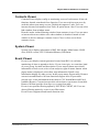
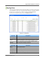
Purpose
Ubigate iBG2016™ iBG-DM User Guide describes the iBG2016 Device
Manager’s features, functions, installation, and operations etc.
Document Content and Organization
This manual is composed of eight chapters.
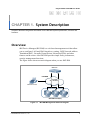
CHAPTER 1. System Description
Overview
iBG-DM Architecture
iBG-DM Functions
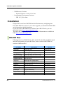
CHAPTER 2. System Installation
System Requirements
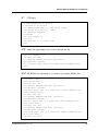
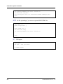
Installation
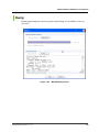
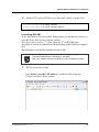
Launching iBG-DM
CHAPTER 3. System Environment
Steps for using iBG-DM
© SAMSUNG Electronics Co., Ltd.
IX
INTRODUCTION
CHAPTER 4. General Operation
Consistence of screen
Menu
CHAPTER 5. Fault Management
Alarm Management
Syslog Management
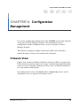
CHAPTER 6. Configuration Management
Chassis View
Module/Port
Interfaces
Layer 2
Routing
Voice Management
QoS
AAA
VPN
Firewall
ISM
DHCP
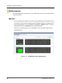
CHAPTER 7. Performance Management
Monitor
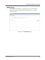
RMON Setup
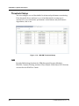
Threshold Setup
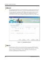
CHAPTER 8. User & Security Management
User ID Management
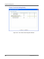
Current Logon Users
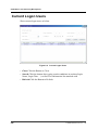
Login History
Command History
X
© SAMSUNG Electronics Co., Ltd.
Ubigate iBG2016 iBG-DM User Guide/Ed.00
Reference
Ubigate iBG2016 System Description
Ubigate iBG2016 Installation Manual
Ubigate iBG2016 Configuration Guide
Ubigate iBG2016 Command Reference
Ubigate iBG2016 Message Reference
Ubigate iBG2016 TroubleShooting Manual
Ubigate iBG2016 Quick Start Guide
Ubigate ISM User Guide
Ubigate iPX User Guide
Contacting Technical Support
For questions regarding the product and the content of this document
Please visit:
http://www.samsungen.com
Obtaining Publications and Additional
Information
The Ubigate iBG2016 documentation set, and additional literature is available at:
http://www.samsungen.com
© SAMSUNG Electronics Co., Ltd.
XI
INTRODUCTION
Revision History
XII
EDITION
DATE OF ISSUE
REMARKS
00
11. 2006.
First Draft
© SAMSUNG Electronics Co., Ltd.
Ubigate iBG2016 iBG-DM User Guide
TABLE OF CONTENTS
GENERAL USER INFORMATION
I
RADIO FREQUENCY INTERFERENCE ...... 오류! 책갈피가 정의되어 있지 않습니다.
FCC REQUIREMENTS ................................ 오류! 책갈피가 정의되어 있지 않습니다.
MUSIC ON HOLD WARNING....................... 오류! 책갈피가 정의되어 있지 않습니다.
DISA WARNING ........................................... 오류! 책갈피가 정의되어 있지 않습니다.
SAFETY WARNING ..................................... 오류! 책갈피가 정의되어 있지 않습니다.
UNDERWRITERS LABORATORIES............ 오류! 책갈피가 정의되어 있지 않습니다.
INTRODUCTION
오류! 책갈피가 정의되어 있지 않습니다.
Purpose ........................................................ 오류! 책갈피가 정의되어 있지 않습니다.
Document Content and Organization ........... 오류! 책갈피가 정의되어 있지 않습니다.
Reference ..................................................... 오류! 책갈피가 정의되어 있지 않습니다.
Contacting Technical Support ....................... 오류! 책갈피가 정의되어 있지 않습니다.
Obtaining Publications and Additional Information오류! 책갈피가 정의되어 있지 않습니
다.
Revision History............................................ 오류! 책갈피가 정의되어 있지 않습니다.
CHAPTER 1.
System Description
1
Overview ............................................................................................................................. 1
iBG-DM Architecture .......................................................................................................... 7
iBG-DM Functions .............................................................................................................. 8
CHAPTER 2.
System Installation
27
System Requirements...................................................................................................... 27
Installation ........................................................................................................................ 28
Launching iBG-DM ........................................................................................................... 35
© SAMSUNG Electronics Co., Ltd.
XIII
TABLE OF CONTENTS
CHAPTER 3.
System Environment
41
Steps for using iBG-DM.................................................................................................... 41
CHAPTER 4.
General Operation
51
Consistence of screen ..................................................................................................... 51
Menu .................................................................................................................................. 57
CHAPTER 5.
Fault Management
93
Alarm Management .......................................................................................................... 93
Syslog Management ......................................................................................................... 95
CHAPTER 6.
Configuration Management
101
Chassis View................................................................................................................... 101
Module/Port..................................................................................................................... 106
Interfaces......................................................................................................................... 120
Layer 2 ............................................................................................................................. 171
Routing ............................................................................................................................ 181
Voice Management ......................................................................................................... 269
QoS .................................................................................................................................. 389
AAA.................................................................................................................................. 397
VPN .................................................................................................................................. 409
Firewall ............................................................................................................................ 477
ISM ................................................................................................................................... 527
DHCP ............................................................................................................................... 528
CHAPTER 7.
Performance Management
539
Monitor ............................................................................................................................ 539
RMON Setup.................................................................................................................... 560
Threshold Setup ............................................................................................................. 573
XIV
© SAMSUNG Electronics Co., Ltd.
Ubigate iBG2016 iBG-DM User Guide/Ed.00
CHAPTER 8.
User & Security Management
579
User ID Management ...................................................................................................... 579
Current Logon Users ..................................................................................................... 582
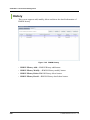
Login History .................................................................................................................. 583
Command History .......................................................................................................... 584
LIST OF FIGURES
Figure 1.1
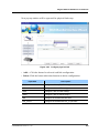
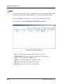
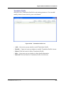
iBG-DM Management Network Diagram.................................................... 1
Figure 1.2
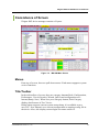
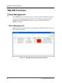
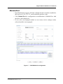
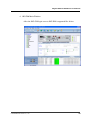
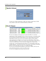
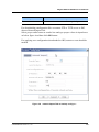
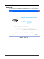
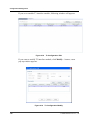
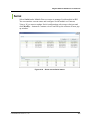
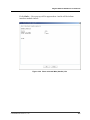
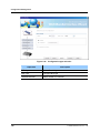
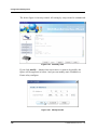
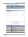
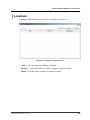
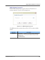
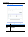
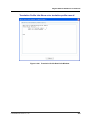
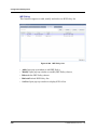
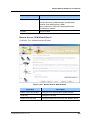
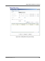
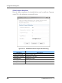
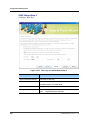
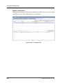
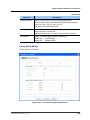
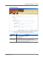
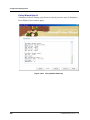
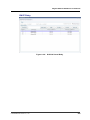
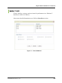
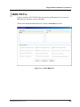
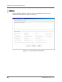
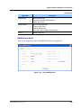
iBG-DM Main Screen ................................................................................. 3
Figure 1.3
iBG-DM Architecture .................................................................................. 7
Figure 1.4
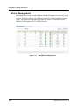
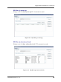
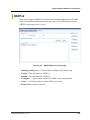
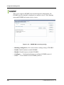
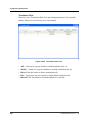
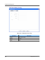
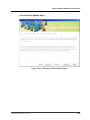
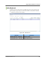
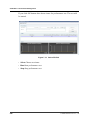
iBG-DM Alarm Management (Active Alarm) ............................................... 8
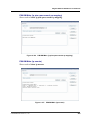
Figure 1.5
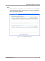
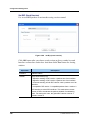
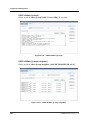
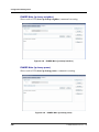
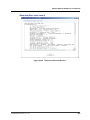
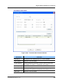
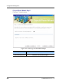
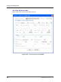
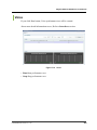
iBG-DM Syslog Management (Syslog View).............................................. 9
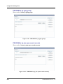
Figure 1.6
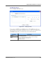
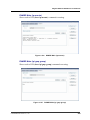
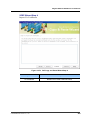
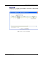
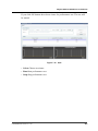
iBG-DM Chassis View.............................................................................. 10
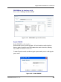
Figure 1.7
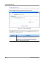
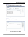
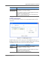
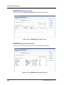
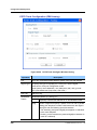
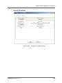
iBG-DM Module configuration .................................................................. 11
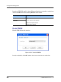
Figure 1.8
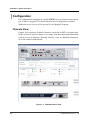
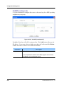
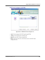
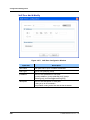
iBG-DM Interface Configuration ............................................................... 12
Figure 1.9
iBG-DM Layer 2 Configuration ................................................................. 12
Figure 1.10
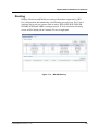
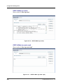
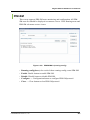
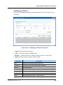
iBG-DM Routing..................................................................................... 13
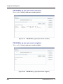
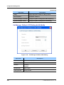
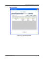
Figure 1.11 iBG-DM Voice Management................................................................... 14
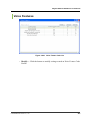
Figure 1.12 iBG-DM QoS Management .................................................................... 15
Figure 1.13 iBG-DM AAA Management..................................................................... 16
Figure 1.14 iBG-DM VPN Management .................................................................... 17
Figure 1.15
iBG-DM Firewall Management ............................................................... 18
Figure 1.16 iBG-DM DHCP Management ................................................................. 19
Figure 1.17
iBG-DM Performance Management....................................................... 20
Figure 1.18 iBG-DM RMON Setup............................................................................ 21
Figure 1.19
iBG-DM Threshold Setup ....................................................................... 22
Figure 1.20
iBG-DM User Management.................................................................... 23
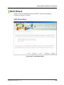
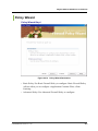
Figure 1.21 iBG-DM Wizard Screen.......................................................................... 24
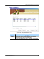
Figure 1.22 iBG-DM Dump Screen ........................................................................... 25
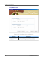
Figure 1.23
iBG-DM Save Config file Screen............................................................ 26
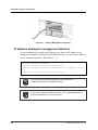
Figure 3.1
Cabling Management Interface ................................................................ 42
© SAMSUNG Electronics Co., Ltd.
XV
TABLE OF CONTENTS
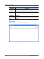
Figure 4.1
iBG-DM Main Screen ............................................................................... 51
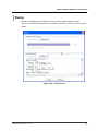
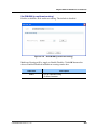
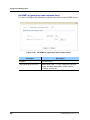
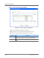
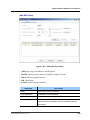
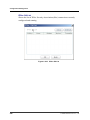
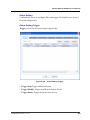
Figure 4.2 File Menu ................................................................................................. 57
Figure 4.3
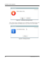
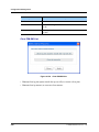
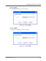
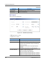
Confirmation massage window ................................................................ 58
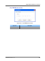
Figure 4.4 Message window...................................................................................... 58
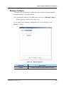
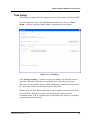
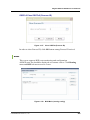
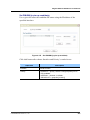
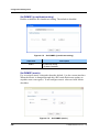
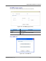
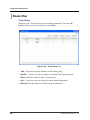
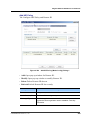
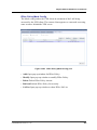
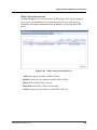
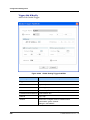
Figure 4.5 Backup Config to … ................................................................................. 59
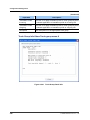
Figure 4.6
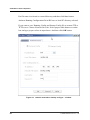
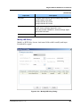
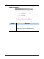
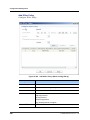
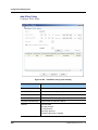
network save tab on backup config to… window...................................... 60
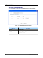
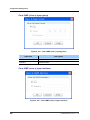
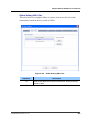
Figure 4.7
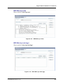
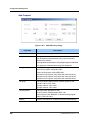
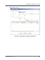
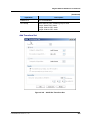
Restore Config from… ............................................................................. 62
Figure 4.8
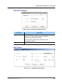
network Import Tab on backup config to… ............................................... 63
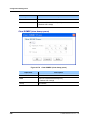
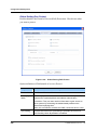
Figure 4.9
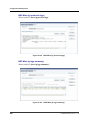
Rollback confirmation message window .................................................. 64
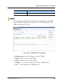
Figure 4.10
System Menu ......................................................................................... 65
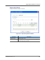
Figure 4.11 Express Wizard initial screen. ................................................................ 66
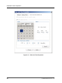
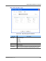
Figure 4.12 Time Setup. ............................................................................................ 67
Figure 4.13 Date and Time Properties....................................................................... 68
Figure 4.14
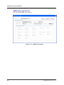
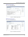
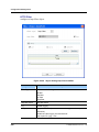
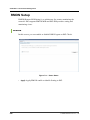
SNMP Setup General View Tab. ............................................................ 69
Figure 4.15
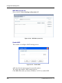
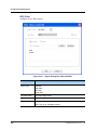
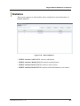
SNMP Setup General Group Tab. .......................................................... 70
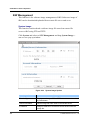
Figure 4.16
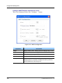
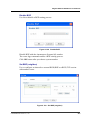
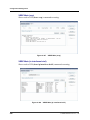
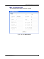
SNMP Setup General User Tab.............................................................. 71
Figure 4.17
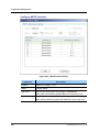
SNMP Trap Control. ............................................................................... 72
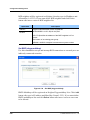
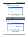
Figure 4.18 SNMP Trap Target Address Entry........................................................... 73
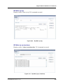
Figure 4.19
Reset To Factory Default........................................................................ 74
Figure 4.20 Save Running Configuration to local PC. ............................................... 74
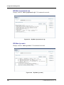
Figure 4.21
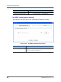
Confirmation Message to default factory reset. ...................................... 75
Figure 4.22 Reset Router Confirmation Message. .................................................... 75
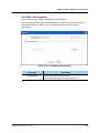
Figure 4.23 System Image Update............................................................................ 76
Figure 4.24 File Upload/Download Device ................................................................ 77
Figure 4.25
Tools Menu............................................................................................. 79
Figure 4.26
Telnet ..................................................................................................... 79
Figure 4.27
Ping ........................................................................................................ 80
Figure 4.28 Trace Route ........................................................................................... 81
Figure 4.29
CLI Browser ........................................................................................... 82
Figure 4.30
CLI Command List ................................................................................. 83
Figure 4.31
CLI Browser ........................................................................................... 84
Figure 4.32
Option .................................................................................................... 85
Figure 4.33 Selectory Directory................................................................................. 86
XVI
Figure 4.34
Window Menu ........................................................................................ 87
Figure 4.35
Event Viewer Enable .............................................................................. 88
Figure 4.36
Event Viewer Disable ............................................................................. 88
Figure 4.37
Help Menu.............................................................................................. 89
Figure 4.38
About This .............................................................................................. 90
© SAMSUNG Electronics Co., Ltd.
Ubigate iBG2016 iBG-DM User Guide/Ed.00
Figure 4.39
Dump Screen ......................................................................................... 91
Figure 5.1
Active Alarm ............................................................................................. 93
Figure 5.2
Alarm History ........................................................................................... 94
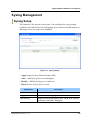
Figure 5.3 Syslog Setup............................................................................................ 95
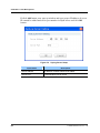
Figure 5.4 Syslog Server Setup ................................................................................ 96
Figure 5.5 Syslog View ............................................................................................. 97
Figure 6.1
Chassis View Image .............................................................................. 102
Figure 6.2
Chassis View Image .............................................................................. 102
Figure 6.3
Chassis View Image .............................................................................. 102
Figure 6.4
overview tab in Chassis View................................................................. 103
Figure 6.5 Interface tab in Chassis View................................................................. 103
Figure 6.6
Routing tab in Chassis View .................................................................. 104
Figure 6.7 Security tab in Chassis View.................................................................. 104
Figure 6.8 Voice tab in Chassis View ...................................................................... 104
Figure 6.9 Module tab in Chassis View ................................................................... 105
Figure 6.10
Env & Resource tab in Chassis View ................................................... 105
Figure 6.11 Clock tab in Chassis View .................................................................... 105
Figure 6.12
WAN Module List ................................................................................. 106
Figure 6.13 T1 Module Modification ........................................................................ 107
Figure 6.14 E1 Module Modification........................................................................ 108
Figure 6.15 Threshold for addition or modification .................................................. 109
Figure 6.16 CT3 WAN Module List.......................................................................... 110
Figure 6.17 CT3 Configuration Edit..........................................................................111
Figure 6.18 T3 Configuration Edit ........................................................................... 112
Figure 6.19 T3 Configuration Modify ....................................................................... 112
Figure 6.20 T1 within CT3 Configuration Edit ......................................................... 113
Figure 6.21
Add threshold....................................................................................... 115
Figure 6.22
Show current HSSI status .................................................................... 116
Figure 6.23
Show current Serial status ................................................................... 117
Figure 6.24
Serial Configuration Edit ...................................................................... 118
Figure 6.25 Show all Wan (bundle) status............................................................... 120
Figure 6.26
Show selected Wan (bundle) info......................................................... 121
Figure 6.27 First step of bundle creation-Setup Wizard .......................................... 122
Figure 6.28 Configue physical link .......................................................................... 123
Figure 6.29
Add a link on card ................................................................................ 124
Figure 6.30
ISDN Configure.................................................................................... 125
© SAMSUNG Electronics Co., Ltd.
XVII
TABLE OF CONTENTS
Figure 6.31 ISDN Configure for Bearer Channel. .................................................... 126
Figure 6.32 ISDN Configure for LAPD..................................................................... 127
Figure 6.33 ISDN Configure for Signal .................................................................... 128
Figure 6.34 ISDN Configure for Advanced .............................................................. 129
Figure 6.35
Encapsulation....................................................................................... 131
Figure 6.36 Configuration type selection ................................................................. 132
Figure 6.37 PPP for General ................................................................................... 133
Figure 6.38
PPP for Authentication ......................................................................... 134
Figure 6.39
IP address setting................................................................................. 135
Figure 6.40
Summary view...................................................................................... 136
Figure 6.41
Modify bundle....................................................................................... 136
Figure 6.42
Modify Frame-relay for general ............................................................ 137
Figure 6.43
Modify bundle....................................................................................... 137
Figure 6.44
Show all AVCs List ............................................................................... 138
Figure 6.45
Show selected Avc info ........................................................................ 139
Figure 6.46
Add AVC............................................................................................... 140
Figure 6.47
Add AVC............................................................................................... 141
Figure 6.48
Modify AVC General ............................................................................. 142
Figure 6.49
Modify AVC Advenced .......................................................................... 143
Figure 6.50 Show all Ethernet status....................................................................... 144
Figure 6.51
Modify Ethernet .................................................................................... 145
Figure 6.52
Show selected Ethernet info................................................................. 146
Figure 6.53
Ethernet Wizard Switching Port............................................................ 147
Figure 6.54
Ethernet Wizard Switching Port summary ............................................ 148
Figure 6.55
Ethernet Wizard Routing Port............................................................... 149
Figure 6.56
Ethernet Wizard Routing Port............................................................... 150
Figure 6.57
Ethernet Wizard ................................................................................... 151
Figure 6.58
Modify Ethernet .................................................................................... 152
Figure 6.59 Show VLAN List ................................................................................... 153
Figure 6.60
VLAN Configuration ............................................................................. 154
Figure 6.61
VLAN Setup ......................................................................................... 155
Figure 6.62 Select Interface Mode (choose Access button) .................................... 156
Figure 6.63 Select Interface Mode (choose Hybrid button) ..................................... 156
Figure 6.64 Select Interface Mode (choose Trunk button)....................................... 157
XVIII
Figure 6.65
Select VLAN......................................................................................... 158
Figure 6.66
Show all Loopback List ........................................................................ 159
Figure 6.67
Add Loopback interface ....................................................................... 160
Figure 6.68
Modify Loopback interface ................................................................... 161
© SAMSUNG Electronics Co., Ltd.
Ubigate iBG2016 iBG-DM User Guide/Ed.00
Figure 6.69
Show all Virtual Access List ................................................................. 162
Figure 6.70
Add Vitual Access interface.................................................................. 163
Figure 6.71
Modify Vitual Access interface ............................................................. 165
Figure 6.72 Show all GRE Tunnel List .................................................................... 167
Figure 6.73
Add GRE Tunnel interface ................................................................... 168
Figure 6.74
Modify GRE Tunnel interface ............................................................... 169
Figure 6.75 Show bridge info .................................................................................. 171
Figure 6.76
GVRP/GMRP/IGS Contents View........................................................ 172
Figure 6.77 Bridge Option Setup............................................................................. 173
Figure 6.78
GVRP/GMRP Port Setup ..................................................................... 174
Figure 6.79 IGMP Snooping VLAN Setup ............................................................... 175
Figure 6.80
802.1X Contents View.......................................................................... 176
Figure 6.81 802.1X Setup ....................................................................................... 176
Figure 6.82
MSTP Contents View ........................................................................... 177
Figure 6.83
MSTP Configuration............................................................................. 178
Figure 6.84
MSTP Instance Setup .......................................................................... 179
Figure 6.85
MSTP Interface Setup.......................................................................... 180
Figure 6.86 Routing Common Main ........................................................................ 181
Figure 6.87 Routing Static Main .............................................................................. 182
Figure 6.88
Add IP Static Route .............................................................................. 183
Figure 6.89 Rip Main (running-config)..................................................................... 184
Figure 6.90 Rip Main (ip rip).................................................................................... 185
Figure 6.91 Rip Main (ip rip interface) ..................................................................... 185
Figure 6.92 Rip Main (ip protocols rip) .................................................................... 186
Figure 6.93 Rip Main (ip route) ............................................................................... 186
Figure 6.94 Rip Main (ip route rip) .......................................................................... 187
Figure 6.95 Rip Main (ip interfaces brief) ................................................................ 187
Figure 6.96
set Rip (version)................................................................................... 188
Figure 6.97
set Rip (receive-version) ...................................................................... 189
Figure 6.98 set Rip (send-version) .......................................................................... 190
Figure 6.99 set Rip (split-horizon) ........................................................................... 191
Figure 6.100
set Rip (network)................................................................................ 192
Figure 6.101
set Rip (rip route) ............................................................................... 193
Figure 6.102
set Rip (redistribute)........................................................................... 194
Figure 6.103
set Rip (passive interface).................................................................. 195
Figure 6.104
clear Rip (clear ip rip) ......................................................................... 196
Figure 6.105
OSPFv2 Main (running-config)........................................................... 197
Figure 6.106
OSPFv2 Main (ip ospf)....................................................................... 198
© SAMSUNG Electronics Co., Ltd.
XIX
TABLE OF CONTENTS
XX
Figure 6.107
OSPFv2 Main (ip ospf neighbor) ........................................................ 198
Figure 6.108
OSPFv2 Main (ip ospf interface) ........................................................ 199
Figure 6.109
OSPFv2 Main (ip ospf database) ....................................................... 199
Figure 6.110
OSPFv2 Main (ip route)...................................................................... 200
Figure 6.111
OSPFv2 Main (ip route ospf) .............................................................. 200
Figure 6.112
OSPFv2 Main (ip interfaces brief)....................................................... 201
Figure 6.113
OSPFv2 Main (router-id) .................................................................... 201
Figure 6.114
OSPFv2 Enable Process ID ............................................................... 202
Figure 6.115
OSPFv2 Disable Process ID .............................................................. 203
Figure 6.116
Set OSPFv2 (network)........................................................................ 204
Figure 6.117
Clear OSPFv2 (Process ID) ............................................................... 205
Figure 6.118
BGP Main (running-config) ................................................................. 205
Figure 6.119
BGP Main (ip bgp) .............................................................................. 206
Figure 6.120
BGP Main (ip route)............................................................................ 207
Figure 6.121
BGP Main (ip route bgp)..................................................................... 207
Figure 6.122
BGP Main (ip protocols bgp) .............................................................. 208
Figure 6.123
BGP Main (ip bgp summary) .............................................................. 208
Figure 6.124
BGP Main (ip bgp neighbor) ............................................................... 209
Figure 6.125
BGP Main (ip interfaces brief) ............................................................ 209
Figure 6.126
BGP Main (router-id) .......................................................................... 210
Figure 6.127
Enable BGP ....................................................................................... 210
Figure 6.128
Disable BGP....................................................................................... 211
Figure 6.129
Set BGP (neighbor) ............................................................................ 211
Figure 6.130
Set BGP (ebgp-multihop) ................................................................... 212
Figure 6.131
Set BGP (update-source) ................................................................... 213
Figure 6.132
Set BGP (nexthop-self) ...................................................................... 214
Figure 6.133
Set BGP (router-id)............................................................................. 215
Figure 6.134
Set BGP (bgp router-id)...................................................................... 216
Figure 6.135
Set BGP (network) ............................................................................. 217
Figure 6.136
Set BGP (redistribute) ........................................................................ 218
Figure 6.137
Set BGP (synchronization) ................................................................. 219
Figure 6.138
Set BGP (soft-reconfiguration) ........................................................... 219
Figure 6.139
Clear BGP (clear ip bgp) .................................................................... 220
Figure 6.140
PIM-SM Main (running-config) ........................................................... 221
Figure 6.141
PIM-SM Main (ip pim sparse-mode interface) .................................... 222
Figure 6.142
PIM-SM Main (ip pim sparse-mode neighbor).................................... 222
Figure 6.143
PIM-SM Main (ip pim sparse-mode nexthop) ..................................... 223
Figure 6.144
PIM-SM Main (ip pim sparse-mode bsr-router) .................................. 223
© SAMSUNG Electronics Co., Ltd.
Ubigate iBG2016 iBG-DM User Guide/Ed.00
Figure 6.145
PIM-SM Main (ip pim sparse-mode rp-hash) ..................................... 224
Figure 6.146
PIM-SM Main (ip pim sparse-mode rp mapping)................................ 225
Figure 6.147
PIM-SM Main (ip mroute) ................................................................... 225
Figure 6.148
PIM-SM Main (ip igmp group) ............................................................ 226
Figure 6.149
PIM-SM Main (ip pim sparse-mode mroute) ...................................... 226
Figure 6.150
PIM-SM Main (ip interfaces brief)....................................................... 227
Figure 6.151
Enable PIM-SM.................................................................................. 227
Figure 6.152
Disable PIM-SM ................................................................................. 228
Figure 6.153
Set PIM-SM (ip multicast-routing) ...................................................... 229
Figure 6.154
Set PIM-SM (ip pim hello-interval) ..................................................... 230
Figure 6.155
Set PIM-SM (ip pim rp-candidate)...................................................... 231
Figure 6.156
Set PIM-SM (ip pim hello-holdtime) ................................................... 232
Figure 6.157
Set PIM-SM (ip pim spt-threshhold) ................................................... 233
Figure 6.158
Set PIM-SM (ip pim bsr-candidate) .................................................... 233
Figure 6.159
Clear PIM-SM List.............................................................................. 234
Figure 6.160
Clear PIM-SM (clear mroute) ............................................................. 235
Figure 6.161
DVMRP Main (running-config) ........................................................... 236
Figure 6.162
DVMRP Main (ip dvmrp) .................................................................... 237
Figure 6.163
DVMRP Main (ip dvmrp interface) ..................................................... 237
Figure 6.164
DVMRP Main (ip dvmrp interface) ..................................................... 238
Figure 6.165
DVMRP Main (ip dvmrp prune) .......................................................... 238
Figure 6.166
DVMRP Main (ip mroute) ................................................................... 239
Figure 6.167
DVMRP Main (ip igmp group) ............................................................ 239
Figure 6.168
DVMRP Main (ip dvmrp route) ........................................................... 240
Figure 6.169
DVMRP Main (ip interfaces brief)....................................................... 240
Figure 6.170
Enable DVMRP.................................................................................. 241
Figure 6.171
Disable DVMRP ................................................................................. 241
Figure 6.172
Set DVMRP (ip multicast-routing) ...................................................... 242
Figure 6.173
Set DVMRP (metric)........................................................................... 242
Figure 6.174
Set DVMRP (report-delay) ................................................................. 243
Figure 6.175
Set DVMRP (reject non prunner) ....................................................... 244
Figure 6.176
Clear DVMRP List .............................................................................. 245
Figure 6.177
Clear DVMRP (clear dvmrp route) ..................................................... 245
Figure 6.178
Clear DVMRP (clear dvmrp prune) .................................................... 246
Figure 6.179
Clear DVMRP (clear mroute) ............................................................. 247
Figure 6.180
IGMP Main (running-config) ............................................................... 247
Figure 6.181
IGMP Main (ip igmp group) ................................................................ 248
Figure 6.182
IGMP Main (ip igmp interface) ........................................................... 249
© SAMSUNG Electronics Co., Ltd.
XXI
TABLE OF CONTENTS
XXII
Figure 6.183
IGMP Main (ip interfaces brief)........................................................... 249
Figure 6.184
Set IGMP (ip multicast-routing) .......................................................... 250
Figure 6.185
Set IGMP (ip igmp access-group) ...................................................... 250
Figure 6.186
Set IGMP (ip igmp immediate-leave).................................................. 251
Figure 6.187
Set IGMP (ip igmp last-member-query-count) .................................... 252
Figure 6.188
Set IGMP (ip igmp last-member-query-interval) ................................. 253
Figure 6.189
Set IGMP (ip igmp querier-timeout).................................................... 254
Figure 6.190
Set IGMP (ip igmp query-interval) ...................................................... 255
Figure 6.191
Set IGMP (ip igmp query-max-response-time) ................................... 256
Figure 6.192
Set IGMP (ip igmp version) ................................................................ 257
Figure 6.193
Clear IGMP List .................................................................................. 257
Figure 6.194
Clear IGMP (clear ip igmp group)....................................................... 258
Figure 6.195
Clear IGMP (clear ip igmp interface) .................................................. 258
Figure 6.196
VRRP Main (running-config) .............................................................. 259
Figure 6.197
VRRP Main (vrrp) ............................................................................... 260
Figure 6.198
VRRP Main (ip interfaces brief) .......................................................... 260
Figure 6.199
Enable VRRP ..................................................................................... 261
Figure 6.200
Disable VRRP .................................................................................... 261
Figure 6.201
Set VRRP (advertisement_interval).................................................... 262
Figure 6.202
Set VRRP (authentication) ................................................................. 263
Figure 6.203
Set VRRP (description) ...................................................................... 264
Figure 6.204
Set VRRP (learn_adv_interval) .......................................................... 265
Figure 6.205
Set VRRP (track)................................................................................ 265
Figure 6.206
Set VRRP (ipaddr).............................................................................. 266
Figure 6.207
Set VRRP (preempt) .......................................................................... 267
Figure 6.208
Set VRRP (enable)............................................................................. 267
Figure 6.209
Set VRRP (priority)............................................................................. 268
Figure 6.210
Show RTP connections List window................................................... 269
Figure 6.211
Show current status of all DSP Display .............................................. 270
Figure 6.212
Show Voice Status Info window.......................................................... 270
Figure 6.213
Voice Test window .............................................................................. 272
Figure 6.214
VoIP Wizard Gateway Configure Step................................................ 273
Figure 6.215
VoIP Standalon Mode Service Selection Step .................................... 274
Figure 6.216
VoIP Call Server Mode Service Selection Step .................................. 275
Figure 6.217
SCM Call Server Configure Step........................................................ 276
Figure 6.218
VoIP SIP Server Configure Step......................................................... 277
Figure 6.219
SIP Server Detail Configure Window.................................................. 278
Figure 6.220
VoIP H.323 Server Configure Step ..................................................... 279
© SAMSUNG Electronics Co., Ltd.
Ubigate iBG2016 iBG-DM User Guide/Ed.00
Figure 6.221
Analog Phone Configure List ............................................................. 280
Figure 6.222
Analog Phone Configure Window ...................................................... 281
Figure 6.223
PBX POTS Trunk Configure Step ...................................................... 283
Figure 6.224
POTS Trunk Configure Window-Analog............................................. 284
Figure 6.225
POTS Trunk Configure Window-Digital .............................................. 286
Figure 6.226
VoIP Trunk Configure List .................................................................. 287
Figure 6.227
VoIP Trunk Configure Window ........................................................... 288
Figure 6.228
PSTN POTS Trunk Configure List...................................................... 289
Figure 6.229
POTS Trunk Configure Window-Analog............................................. 290
Figure 6.230
POTS Trunk Configure Window-Digital .............................................. 291
Figure 6.231
VoIP Wizard Configuration Summary................................................. 292
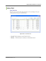
Figure 6.232
Voice Port List .................................................................................... 293
Figure 6.233
FXS Port Configure Window .............................................................. 294
Figure 6.234
FXO Port Configure Window.............................................................. 297
Figure 6.235
E & M Port Configure Window ........................................................... 299
Figure 6.236
Analog Voice Port Detail Configuration-signal tab.............................. 301
Figure 6.237
Analog Voice Port Detail Configuration Window-Connection tab ....... 304
Figure 6.238
Voice port Busyout Monitor Setting Window ...................................... 306
Figure 6.239
Digital Voice Port Configuration Window............................................ 307
Figure 6.240
Digital Voice Port CasCustorm Configuration Window ....................... 309
Figure 6.241
Digital Voice Port Detail Configuration Window-Signal Tab................ 310
Figure 6.242
Digital Voice Port Detail Configuration Window-Connection Tab........ 312
Figure 6.243
Voice Port Status List ......................................................................... 314
Figure 6.244
Voice Port Status Detail Info............................................................... 315
Figure 6.245
Dial-peer Extension List ..................................................................... 316
Figure 6.246
Dial-peer Extension Add/Modify ......................................................... 317
Figure 6.247
Dial-peer Extension Multi-copy .......................................................... 320
Figure 6.248
Dial-peer Detail Info Window.............................................................. 321
Figure 6.249
Dial-peer Trunk List............................................................................ 322
Figure 6.250
Dial-peer POTS Trunk Add/Modify Window ....................................... 323
Figure 6.251
Dial-peer VoIP Trunk Add/Modify Window.......................................... 326
Figure 6.252
Dial-peer POTS/VoIP Trunk Detail (Common) Configure Window ..... 330
Figure 6.253
Dial-peer POTS Trunk multi-copy ...................................................... 332
Figure 6.254
Dial-peer VoIP Trunk multi-copy......................................................... 333
Figure 6.255
IP Phone List...................................................................................... 334
Figure 6.256
Dial Peer COR List............................................................................. 335
Figure 6.257
Dial Peer COR list Create Window .................................................... 336
Figure 6.258
Dial Peer COR Custom Create Window ............................................ 337
© SAMSUNG Electronics Co., Ltd.
XXIII
TABLE OF CONTENTS
XXIV
Figure 6.259
Trunk Group List................................................................................. 338
Figure 6.260
Trunk Group Creation Window ........................................................... 339
Figure 6.261
Trunk Group Detail Info ...................................................................... 340
Figure 6.262
Translation Profile List........................................................................ 341
Figure 6.263
Translation Profile Creation Window .................................................. 342
Figure 6.264
Translation Profile Detail Info Window................................................ 343
Figure 6.265
Translation Rule List........................................................................... 344
Figure 6.266
Translation Rule Creation Window ..................................................... 345
Figure 6.267
Translation Profile Detail Info Window................................................ 348
Figure 6.268
Dial Plan Configuration Window......................................................... 349
Figure 6.269
Fxs Pattern Creation Window............................................................. 350
Figure 6.270
Num Expression Creation Window..................................................... 351
Figure 6.271
VoIP Gateway Configuration .............................................................. 352
Figure 6.272
VoIP Gateway SIP Configuration-Server Tab ..................................... 355
Figure 6.273
VoIP Gateway SIP Configuration-Protocol Tab................................... 357
Figure 6.274
VoIP Gateway H.323 Configuration.................................................... 359
Figure 6.275
Voice Service POTS(Global) Configuration........................................ 361
Figure 6.276
VoIP Peer List .................................................................................... 363
Figure 6.277
VoIP Peer Configuraion Window ........................................................ 364
Figure 6.278
Call Manager Fallback Configuration ................................................. 365
Figure 6.279
Call Manager Fallback COR Setting .................................................. 366
Figure 6.280
Voice Feature Code List ..................................................................... 367
Figure 6.281
Voice Feature Code Configuration Window........................................ 368
Figure 6.282
Voice Class List.................................................................................. 369
Figure 6.283
Voice Class Codec Configuration Window ......................................... 370
Figure 6.284
Voice Class Busyout Configuration Window....................................... 371
Figure 6.285
Voice Class SIP Configuration Window.............................................. 372
Figure 6.286
Voice Class H.323 Configuration Window .......................................... 373
Figure 6.287
VoIP SIP Protocol Configuration......................................................... 375
Figure 6.288
VoIP SIP Protocol Clear Cause Mapping ........................................... 376
Figure 6.289
VoIP H.323 Protocol Configuration..................................................... 377
Figure 6.290
Voice Access Group List..................................................................... 378
Figure 6.291
Access Group Configuration Window................................................. 379
Figure 6.292
Access List Configuration Window ..................................................... 380
Figure 6.293
Access Group Detail Info Display Window ......................................... 382
Figure 6.294
Call Admission Control Configuration ................................................. 383
Figure 6.295
Call Threshold Interface Configuration Window ................................. 385
Figure 6.296
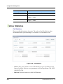
Call Statistics...................................................................................... 386
© SAMSUNG Electronics Co., Ltd.
Ubigate iBG2016 iBG-DM User Guide/Ed.00
Figure 6.297
SIP Protocol Method Statistics ........................................................... 387
Figure 6.298
SIP Protocol Statistics ........................................................................ 387
Figure 6.299
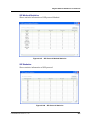
H.323 Protocol Statistics .................................................................... 388
Figure 6.300
Dial Peer Statistics ............................................................................. 388
Figure 6.301
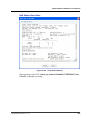
interface class .................................................................................... 389
Figure 6.302
View QoS of Bundle test ppp ............................................................. 390
Figure 6.303
View QoS of Bundle ........................................................................... 391
Figure 6.304
Copy&Paste QoS Class ..................................................................... 392
Figure 6.305
Modify QoS Class .............................................................................. 393
Figure 6.306
Modify QoS Class-Config................................................................... 394
Figure 6.307
Modify QoS Class-RED ..................................................................... 395
Figure 6.308
Modify QoS Class-RED ..................................................................... 396
Figure 6.309
AAA Status ......................................................................................... 397
Figure 6.310
AAA Servers....................................................................................... 398
Figure 6.311
Trace Server Setting .......................................................................... 399
Figure 6.312
Radius Server Setting ........................................................................ 400
Figure 6.313
Authentication .................................................................................... 401
Figure 6.314
Authentication-Login Add/Modify........................................................ 402
Figure 6.315
Authentication-Protocols Add/Modify ................................................. 403
Figure 6.316
Authorization ...................................................................................... 404
Figure 6.317
Authorization-Commands Add/Modify................................................ 405
Figure 6.318
Accounting ......................................................................................... 406
Figure 6.319
Accounting Add/Modify ...................................................................... 407
Figure 6.320
Zone Configuration ............................................................................ 409
Figure 6.321
Site-to-Site VPN Wizard: Site-to-Site and GRE over IPSec ............... 410
Figure 6.322
Site to Site-Step 1 .............................................................................. 411
Figure 6.323
Site to Site-Step 2 .............................................................................. 412
Figure 6.324
Site to Site-Step 3 .............................................................................. 413
Figure 6.325
Site to Site-Step 4 .............................................................................. 414
Figure 6.326
GRE Tunnel Wizard-Step 1 ................................................................ 415
Figure 6.327
GRE Tunnel Wizard-Step 2 ................................................................ 416
Figure 6.328
GRE Tunnel Wizard-Step 3 ................................................................ 417
Figure 6.329
IKE Policy List .................................................................................... 418
Figure 6.330
Add IKE Policy Dialog ........................................................................ 419
Figure 6.331
Add IKE Proposal Dialog.................................................................... 420
Figure 6.332
Modify IKE Policy Dialog .................................................................... 421
Figure 6.333
IKE-SA List Dialog.............................................................................. 422
Figure 6.334
IPSec Policy List ................................................................................ 423
© SAMSUNG Electronics Co., Ltd.
XXV
TABLE OF CONTENTS
XXVI
Figure 6.335
Add IPSec Policy Dialog..................................................................... 424
Figure 6.336
Add IPSec Transform Set Dialog........................................................ 426
Figure 6.337
Modify IPSec Dialog ........................................................................... 427
Figure 6.338
IPSec SA-List Dialog .......................................................................... 428
Figure 6.339
GRE Over IPSec List.......................................................................... 429
Figure 6.340
Modify GRE Tunnel Policy.................................................................. 430
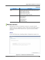
Figure 6.341
Remote Access Wizard Launcher ...................................................... 431
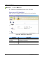
Figure 6.342
Remote Access Wizard-Step 1........................................................... 432
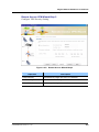
Figure 6.343
Remote Access Wizard-Step 2........................................................... 433
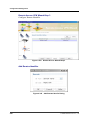
Figure 6.344
Remote Access Wizard-Step 3........................................................... 434
Figure 6.345
Add Remote Idenfier Dialog ............................................................... 434
Figure 6.346
Remote Access Wizard-Step 4........................................................... 435
Figure 6.347
Add Radius Server Dialog .................................................................. 436
Figure 6.348
Remote Access Wizard-Step 5........................................................... 437
Figure 6.349
IKE Policy (Mode Config) List............................................................. 438
Figure 6.350
Add IKE Policy (Mode Config) Dialog-1.............................................. 439
Figure 6.351
Add Remote Indentifier Dialog ........................................................... 440
Figure 6.352
Add IKE Policy (Mode Config) Dialog-2.............................................. 441
Figure 6.353
Add IKE Policy Dialog ........................................................................ 442
Figure 6.354
IKE Policy (User Group) List .............................................................. 443
Figure 6.355
Add IKE Policy (User Group) Dialog .................................................. 444
Figure 6.356
Add Remote Identifier Dialog ............................................................. 445
Figure 6.357
Add IKE Proposal Dialog.................................................................... 445
Figure 6.358
IPSec Policy (Mode Config) List......................................................... 447
Figure 6.359
Add IPSec Policy (Mode Config) Dialog ............................................. 448
Figure 6.360
Add IPSec Transform Set Dialog........................................................ 449
Figure 6.361
Modify IPSec Policy (Mode Config) Dialog......................................... 451
Figure 6.362
IPSec SA List ..................................................................................... 452
Figure 6.363
IPSec Policy (User Group) List........................................................... 453
Figure 6.364
Add IPSec Policy (User Group).......................................................... 454
Figure 6.365
Add IPSec Trasnform Set................................................................... 455
Figure 6.366
Modify IPSec Policy (User Group)...................................................... 457
Figure 6.367
Select an enrollment method.............................................................. 458
Figure 6.368
SCEP Wizard-Step 1 .......................................................................... 459
Figure 6.369
SCEP Wizard-Step 2 .......................................................................... 460
Figure 6.370
SCEP Wizard-Step 3 .......................................................................... 461
Figure 6.371
SCEP Wizard-Other Subject Attribute Dialog ..................................... 462
Figure 6.372
SCEP Wizard-Step 4 .......................................................................... 463
© SAMSUNG Electronics Co., Ltd.
Ubigate iBG2016 iBG-DM User Guide/Ed.00
Figure 6.373
SCEP Wizard-Step 5.......................................................................... 464
Figure 6.374
PKI Copy and Paste Wizard-Step 1 ................................................... 465
Figure 6.375
PKI Copy and Paste Wizard-Step 2 ................................................... 466
Figure 6.376
PKI Copy and Paste Wizard-Step 3 ................................................... 467
Figure 6.377
PKI Copy and Paste Wizard-Other Subject Attribute Dialog .............. 468
Figure 6.378
PKI Copy and Paste Wizard-Step 4 ................................................... 469
Figure 6.379
PKI Copy and Paste Wizard-Step 5 ................................................... 470
Figure 6.380
PKI Copy and Paste Wizard-Step 6 ................................................... 471
Figure 6.381
PKI Copy and Paste Wizard-Step 7 ................................................... 472
Figure 6.382
PKI Copy and Paste Wizard-Step 8 ................................................... 473
Figure 6.383
Trustpoint List..................................................................................... 474
Figure 6.384
Trustpoint List Detail Dialog ............................................................... 475
Figure 6.385
Check Revocation Dialog................................................................... 476
Figure 6.386
Map Config......................................................................................... 477
Figure 6.387
Firewall Map Add/Modify .................................................................... 478
Figure 6.388
Global Setting-Trigger ........................................................................ 479
Figure 6.389
Global Setting-Trigger Add/Edit.......................................................... 480
Figure 6.390
Global Setting-URL Filter ................................................................... 481
Figure 6.391
Global Setting-DoS Protect ................................................................ 482
Figure 6.392
Global Setting-Timeout ...................................................................... 484
Figure 6.393
Global Setting-Logging ...................................................................... 485
Figure 6.394
Global Setting-NAT FailOver .............................................................. 487
Figure 6.395
Global Setting-Timeout Primary, Backup Interface............................. 487
Figure 6.396
Global Setting-ETC ............................................................................ 488
Figure 6.397
Policy ................................................................................................. 489
Figure 6.398
Firewall Policy Multi Add - Global....................................................... 490
Figure 6.399
Friewall Policy Multi Add-Advanced ................................................... 492
Figure 6.400
Firewall Policy Modify ........................................................................ 494
Figure 6.401
Friewall Policy Modify-Advanced ....................................................... 495
Figure 6.402
Object Setting .................................................................................... 497
Figure 6.403
Object Setting-Service ....................................................................... 498
Figure 6.404
Object Setting-Service Add/Edit ......................................................... 499
Figure 6.405
Object Setting-Address ...................................................................... 500
Figure 6.406
Object Setting-Address Add/Edit........................................................ 501
Figure 6.407
Object Setting-Filter ........................................................................... 502
Figure 6.408
Object Setting-Ftp Filter Add/Edit....................................................... 503
Figure 6.409
Object Setting-Http Filter Add/Edit ..................................................... 504
Figure 6.410
Object Setting-Smtp Filter Add/Edit.................................................... 505
© SAMSUNG Electronics Co., Ltd.
XXVII
TABLE OF CONTENTS
Figure 6.411
Object Setting-Rpc Filter Add/Edit ...................................................... 506
Figure 6.412
Object Setting-Schedule..................................................................... 507
Figure 6.413
Object Setting-Schedule Filter Add/Edit ............................................. 508
Figure 6.414
Object Setting-NAT Pool .................................................................... 509
Figure 6.415
Object Setting-NAT Pool Add/Edit ...................................................... 510
Figure 6.416
Policy Wizard-Destination .................................................................. 511
Figure 6.417
Policy Wizard-Direction and Traffic..................................................... 512
Figure 6.418
Policy Wizard-Select Policy................................................................ 513
Figure 6.419
Policy Wizard-Source and Destination ............................................... 514
Figure 6.420
Policy Wizard-Action and Protocol,Service ........................................ 515
Figure 6.421
Policy Wizard-NAT ............................................................................. 516
Figure 6.422
Policy Wizard-Select Schedule .......................................................... 517
Figure 6.423
Policy Wizard-Application contents Filter ........................................... 518
Figure 6.424
Policy Wizard-Rate Limit .................................................................... 519
Figure 6.425
Policy Wizard-Summary ..................................................................... 520
Figure 6.426
ACL-Rule List ..................................................................................... 521
Figure 6.427
Access Control List Add/Edit .............................................................. 522
Figure 6.428
ACL-Group List .................................................................................. 524
Figure 6.429
Access List Mapping .......................................................................... 525
Figure 6.430
ALG .................................................................................................... 526
Figure 6.431
NAT .................................................................................................... 527
Figure 6.432
DHCPv4 Server/Relay........................................................................ 528
Figure 6.433
Add Interface...................................................................................... 529
Figure 6.434
Add DHCP Relay................................................................................ 529
Figure 6.435
DHCP Server Pool Add/Edit ............................................................... 530
Figure 6.436
Exclude Ranget.................................................................................. 531
Figure 6.437
DHCP Server Pool Add-Router .......................................................... 531
Figure 6.438
DHCP Server Pool Add-DNS ............................................................. 532
Figure 6.439
DHCP Server Pool Add-NetBIOS ....................................................... 533
Figure 6.440
DHCP Server Pool Add-Misc.............................................................. 534
Figure 6.441
DHCPv4 Server/Relay........................................................................ 535
Figure 6.442
DHCP Relay-Multi Add ....................................................................... 536
Figure 6.443
DHCP Relay ....................................................................................... 537
Figure 6.444
DHCPv4 Clients ................................................................................. 538
Figure 7.1 System Resource................................................................................... 540
Figure 7.2
Select Interfaces Information.................................................................. 541
Figure 7.3 Interface ................................................................................................. 542
XXVIII
© SAMSUNG Electronics Co., Ltd.
Ubigate iBG2016 iBG-DM User Guide/Ed.00
Figure 7.4 Select WAN Info..................................................................................... 543
Figure 7.5 WAN T1/E1 ............................................................................................ 544
Figure 7.6 Select WAN Info..................................................................................... 545
Figure 7.7
WAN CT3............................................................................................... 546
Figure 7.8
Select Interfaces Information ................................................................. 547
Figure 7.9
WAN PPP .............................................................................................. 548
Figure 7.10 Select WAN Info................................................................................... 549
Figure 7.11 Select WAN FR .................................................................................... 550
Figure 7.12 Select WAN Info................................................................................... 551
Figure 7.13
Select FR PVC..................................................................................... 552
Figure 7.14 Select WAN Info................................................................................... 553
Figure 7.15
WAN FR AVC ....................................................................................... 554
Figure 7.16
Voice .................................................................................................... 555
Figure 7.17 Select QoS Information ........................................................................ 556
Figure 7.18
QoS...................................................................................................... 557
Figure 7.19
Select Interfaces Information ............................................................... 558
Figure 7.20
Rmon ................................................................................................... 559
Figure 7.21
Rmon Status ........................................................................................ 560
Figure 7.22
Rmon Statistics .................................................................................... 561
Figure 7.23
Modify RMON Statistics ....................................................................... 562
Figure 7.24
Show RMON Statistics ......................................................................... 563
Figure 7.25
RMON History...................................................................................... 564
Figure 7.26
Modify RMON History .......................................................................... 565
Figure 7.27
RMON History History.......................................................................... 566
Figure 7.28
RMON Alarm........................................................................................ 567
Figure 7.29
Modify RMON Alarm ............................................................................ 568
Figure 7.30 Show RMON Alarm.............................................................................. 569
Figure 7.31
RMON Event........................................................................................ 570
Figure 7.32
Modify RMON Event ............................................................................ 571
Figure 7.33
RMON Event Detail.............................................................................. 572
Figure 7.34
RMON Log Detail................................................................................. 573
Figure 7.35
E1 2/0l.................................................................................................. 574
Figure 7.36 T1E1 Traffic Base ................................................................................ 575
Figure 7.37
CT3 1/0 ................................................................................................ 576
Figure 7.38
CT3 1/0 ................................................................................................ 577
Figure 8.1
User ID Management............................................................................. 579
Figure 8.2
Create Local user................................................................................... 580
© SAMSUNG Electronics Co., Ltd.
XXIX
TABLE OF CONTENTS
XXX
Figure 8.3
User ID Management ............................................................................. 581
Figure 8.4
Current Logon Users .............................................................................. 582
Figure 8.5
Login History .......................................................................................... 583
Figure 8.6
Command History .................................................................................. 584
© SAMSUNG Electronics Co., Ltd.
Ubigate iBG2016 iBG-DM User Guide
CHAPTER 1. System Description
Chapter1 describes the general information for the iBG-DM system specification, structure and
functions.
Overview
iBG Device Manager(iBG-DM) is a web based management tool that allow
you to configure LAN and WAN interfaces, routing, VoIP, Network address
Translation(NAT), firewalls,Virtual Private Networks(VPNs) and other
features on the router. Also iBG-DM provide simple fault, performance,
security management functions.
The figure below shows network diagram when you use iBG-DM.
iBG2016
LAN/WAN
CLI/SNMP
SSH./SNMPv3
Network Printer
iBG-DM Clients(PC)
Figure 1.1 iBG-DM Management Network Diagram
© SAMSUNG Electronics Co., Ltd.
1
CHAPTER 1. System Description
Network Configuration
Network Interface
Following table shows network interface protocol used by the iBG-DM for
iBG mangement
Table 1.1 Network Interface Protocol
Device
iBG
Management Protocol
SNMPv1/v2 for Normal Mode
SNMP v3 for Secure Mode
Telnet based CLI for Normal Mode
SSH v2 based CLI for Secure Mode
Network Configuration
iBG-DM will be used at any location of user side. It is run on user’s Desktop
and Note PC.
For Network Configuration, iBG-DM can connect to iBG through LAN/WAN
or direct connect by iBG’s management port.
Client System Sepecification
To perform iBG-DM, User need PC with following specification.
Sub item
2
Detail
Processor
Intel Pentium III or faster(Pentium 4 or later Recommended)
Main Memory
DDR SDRAM 512MB or more
Hard Disk
60GB or more
Monitor
17” Monitor-1024x768 resolution higher
OS
Windows 2000/XP, 2000 Server
Web Browser
Internet Explore 6.0 or later
JRE
JRE 1.4.2_08 or later
© SAMSUNG Electronics Co., Ltd.
Ubigate iBG2016 iBG-DM User Guide/Ed.00
Consistence of Screen
Ubigate iBG device manager consists of 6 parts.
Figure 1.2 iBG-DM Main Screen
Menus
From top of screen, there are pull down menus. Each menu suppports system
service functions.
Title/Toolbar
In the title/toolbar of screen, there are category buttons(Fault, Configuration,
Performance, User & Security, Wizard, Quick) and configuration save
buttons(Dump, Save). When user press category button, Each Category
display detail menus in Tree Viewer.
Dump button supports current system status dump, it is available to save
user’s PC. Save button is save current configuration to running-config file in
the device. Also, title display current login user name and level.
© SAMSUNG Electronics Co., Ltd.
3
CHAPTER 1. System Description
TreeViewer
TreeViewer display detail menus of each categories.
Configuration category of Treeviewer activate when user press config
category button. It supports Chassis, Module(T1/E1, CT3/T3, HSSI,Serial),
Interfaces(WAN, AVC, Ethernet, VLAN, Loopback, Virtual Access, Tunnel),
Layer2(GVRP/GMRP/IGS), Routing(Status, Static, RIP, OSPFv2, BGP, PIMSM, DVMRP, IGMP, VRRP), Voice(Voice Status, Wizard, Voice Port, Dialpeer, Route plan, VoIP Gateway, VoIP Server, Voice Features, Voice Class,
VoIP protocol, Access Group, Call Admission Control, Voice Statistics),
QoS(QoS Status), AAA(Status, AAA Servers, Authentication, Authorization,
Accounting), VPN(Zone Configuration, Site-to-Site, Remote Access, PKI
Object), Firewall(Map Config, Policy, ACL-List, NAT), DHCP
Fault category of Treeviewer activate when user press fault category button.
It supports Alarm Management(Active Alarm, Alarm History), System Log
Management(SysLog Setup, SysLog View)
Monitor category of Treeviewer activate when user press performance
category button. It supports Monitor(System Resource, Interface, WAN T1E1,
WAN CT3, WAN PPP, WAN FR, WAN FR PVC, WAN FR AVC, Voice, QoS,
RMON), RMON(RMON Global, RMON Statistics, RMON History, RMON
Alarm, RMON Event), Threshold Setup(Resource base, T1E1 Traffic base,
T3E3 Traffic base), ISM(Report Configuration-When ISM board activate
only)
User & Security category of Treeviewer activate when user press
user & security button. It supports user ID Management, Current Logon users,
Login History, Command History.
Wizard category of Treeviewer activate when user press wizard category
button. It is set of wizards from each configuration menu. It suppports
Firewall policy, QoS, Bundle, Ethernet, Voice, Site to Site, GRE over IPSec,
Remote Access, Simple Certificate Enrollment, Copy and Paste/Import from
PC, ISM-When ISM board activate only)
Quick category of Treeviewer activate when user press quick category button.
It is set of frequently used menus from each menus. It supports chassis,
module/port, Interfaces, Layer2, Routing, Alarm Management, System Log
Management, Monitor.
4
© SAMSUNG Electronics Co., Ltd.
Ubigate iBG2016 iBG-DM User Guide/Ed.00
Contents Viewer
ContetnsViewer display config or monitoring screen of each menus. It has tab
function, detatch, attach and close function. User can switch screen press by
each tabs when open many screens. Default tab supports 5 tabs. User can
increase/decrease tab number from Tools option menu. Also User can select
hide window from window menu.
Detach is make isolated floating window from contents viewer. User can move
or increase/decrease window size when window is detached. Attach is back
window to device manager contents viewer. Close is close screen from
contents viewer.
System Viewer
System viwer display information of iBG. Info display Model name, SNOS
class, SNOS version, CPU Utilization/Memory Utilization.
Event Viewer
Event viewer display current generated events from iBG. it is real-time
monitoring of what is append to device. Event viewer give to event time, kind
of event, group, location and description. If user want to know more detail
information of each event, select event and press right of mouse button. when
popup menu is displayed, select show trap information. Detail event
information display by other screen. In the popup menu, Export table, Remove
current item and Remove All item functions support Also. Export table
provide save events information in the table to CSV format(Microsoft Excel
readable).Remove Current item provide selected one event remove from table.
Remove All Item provide clean up every events from table.
Event viewer provide filtering option by SYSTEM, CLIENT, All. User can
choose filtering option by event viewer filter menu.
Event Viewer supports detach/attach function also.
© SAMSUNG Electronics Co., Ltd.
5
CHAPTER 1. System Description
Management Functions
Configuration Management
The iBG-DM manages configuration of the iBG, and controls it.
Fault Management
The iBG-DM displays fault data in real time, which means that the iBG-DM
transfers the fault data received from the iBG to the user swiftly. Also, the
iBG-DM can display and browse historical alarm with limitation. The iBGDM can display and browse syslog information.
Performance Management
The iBG-DM collects performance data on the iBG. It can monitor each
performance factors on iBG with real-time.
Security Management
The iBG-DM manages users by levels to limit an access to the iBG. Also, the
iBG-DM display operation history, so that the user can perform tracking when
required.
General Managemnt
The iBG-DM privides other gerneral management functions such as
configration saving, exportng and printing, and so on.
6
© SAMSUNG Electronics Co., Ltd.
Ubigate iBG2016 iBG-DM User Guide/Ed.00
iBG-DM Architecture
Introduction
iBG-DM has 3 layer Architecture. There are Protocol APIs/Communcation
Framework/ GUI Framework.
Protocol APIs provide connection to iBG with CLI/SNMP protocol. This API
also provide secure connection to iBG with SNMP v3 and SSHv2 protocol.
Communication Framework provide handling of each Data from Protocol
APIs. It analyze and cook protocol data and transport to GUI Framework.
GUI Framework provide display of information with each functions(Fault,
Configuration, Performance, Security).
GUI
Framework
FM
CM
SM
Alarm/Event Basic Module
GUI Interface
Communication
Framework
Protocol APIs
PM
CORE
Protocol Interface
CLI API
SNMP API
Other API
Figure 1.3 iBG-DM Architecture
© SAMSUNG Electronics Co., Ltd.
7
CHAPTER 1. System Description
iBG-DM Functions
Fault Management
Click FAULT icon on skin menu bar on top part of Device Manage program
for executing fault management functions. The detail function list of fault
management would be displayed on tree viewer at left part on Device
Manager Program.
Alarm Management
Display all current active alarms for monitoring on iBG and alarms issued on
iBG within time period.
Figure 1.4 iBG-DM Alarm Management (Active Alarm)
8
© SAMSUNG Electronics Co., Ltd.
Ubigate iBG2016 iBG-DM User Guide/Ed.00
Syslog Management
This function is for general syslog setup. And all system logs would be list up
on SysLog window.
Figure 1.5 iBG-DM Syslog Management (Syslog View)
© SAMSUNG Electronics Co., Ltd.
9
CHAPTER 1. System Description
Configuration
For configuration management, click CONFIG icon on skin menu bar on top
part of Device program. The detail function list of configuration would be
displayed on tree viewer at left part on Device Manager Program.
Chassis View
Chassis View monitors all kind of interface cards slot in iBG’s rear panel and
LEDs in front of panel as chassis view image. And then important information
such as Overview, Interface, Routing, Security, voice etc should be displayed
as on tab windows individually.
Figure 1.6 iBG-DM Chassis View
10
© SAMSUNG Electronics Co., Ltd.
Ubigate iBG2016 iBG-DM User Guide/Ed.00
Module/Port
This Module/Port supports all kinds of WAN interface modules installed in
iBG such as T1/E1, CT3/T3, serial and HSSI interface cards.
Click Module/Port for configuration or modification of Module/Port. And
interface card is displayed.
If user select not-equipped module on tree menu, device manager notify
selected module is not equipped.
Figure 1.7 iBG-DM Module configuration
© SAMSUNG Electronics Co., Ltd.
11
CHAPTER 1. System Description
Interfaces
You can monitor and configure to all WAN, AVC, Ethernet, VLAN, Loopback
interfaces.
Figure 1.8 iBG-DM Interface Configuration
Layer 2
Interfaces which are configured to switch port and bridge-group can be used in
Layer2 and use GVRP, GMRP, IGMP Snooping, 802.1X protocols.
Figure 1.9 iBG-DM Layer 2 Configuration
12
© SAMSUNG Electronics Co., Ltd.
Ubigate iBG2016 iBG-DM User Guide/Ed.00
Routing
Display all unicast and Multicast routing information supported by iBG.
For configuration and monitoring, click Routing tree menu on Tree Viewer.
And then show sub-tree menus such as static, RIP, OSPF, BGP, PIM-SM,
DVMRP, IGMP and VRRP routing protocols. If click sub-menu, Routing
screen will be displayed on Contents Viewer at right part.
Figure 1.10 iBG-DM Routing
© SAMSUNG Electronics Co., Ltd.
13
CHAPTER 1. System Description
Voice Management
Providing Voice setup wizard function which is designed to Voice setup step
by step. You can configure the VoIP rtp connection, digital signal processor
(DSP) voice channels and manage VoIP call statistics, VoIP SIP Protocol
Method, VoIP statistics-H.323 on iBG Device.
Figure 1.11 iBG-DM Voice Management
14
© SAMSUNG Electronics Co., Ltd.
Ubigate iBG2016 iBG-DM User Guide/Ed.00
QoS
The Quality of Service(QoS) allows a network administrator to enable Quality
of Service(QoS) on the router’s WAN interfaces. QoS can also be enabled on
IPSec VPN interfaces and tunnels.
Figure 1.12 iBG-DM QoS Management
© SAMSUNG Electronics Co., Ltd.
15
CHAPTER 1. System Description
AAA
Authentication, Authorization, and Accounting(AAA) is an architectural
framework for configuring a set of three independent security functions in a
consistent manner. AAA provides a modular way of performing authentication,
authorization, and accounting services.
Figure 1.13 iBG-DM AAA Management
16
© SAMSUNG Electronics Co., Ltd.
Ubigate iBG2016 iBG-DM User Guide/Ed.00
VPN
A Virtual Private Network(VPN) lets you protect traffic that travels over lines
that your organization may not own or control. VPNs can encrypt traffic sent
over these lines and authenticate peers before any traffic is sent.
You can configure VPN easily through iBG-DM and clicking the VPN menu
is the start. When you use the Wizard in the Site-to-Site VPN menu, iBG-DM
provides default values for some configuration parameters in order to simplify
the configuration process.
Figure 1.14 iBG-DM VPN Management
© SAMSUNG Electronics Co., Ltd.
17
CHAPTER 1. System Description
Firewall
Map Configure: Configure Firewall Map on iBG. A firewall map is a zone
for firewall to which different firewall policy be configured.
Policy: Configure the firewall policies. First you can see the current policy
list for the selected Map.
ACL-Rule List: Configure Access Control List for your iBG. You can see
the ACL list for IP rule set, firstly.
ACL-Group List: Shows the ACL Group list of the chosen interface.
NAT: NAT(Network Address Translation) list is displayed. The NAT is
configured at Firewall Policy sub-functions: Policy Add and Object…
Figure 1.15 iBG-DM Firewall Management
18
© SAMSUNG Electronics Co., Ltd.
Ubigate iBG2016 iBG-DM User Guide/Ed.00
ISM
ISM(Integrated Security Module) provide premium security fuctions. It is
supported with ISM board and software. If user installed the ISM module,
GUI functions will be activated.
DHCP
Dynamic Host Configuration Protocol(DHCP) provides a mechanism for
allocating IP addresses to hosts dynamically, so that addresses can be reused
when hosts no longer need them.
Figure 1.16 iBG-DM DHCP Management
© SAMSUNG Electronics Co., Ltd.
19
CHAPTER 1. System Description
Performance
You can monitor the performance of you iBG and can set several performance
related attributes.
Monitor
Every performance monitor screen has same polling period. Default value is
5 Seconds. If you want to change period, Change parameter Polling period
for synchronization. It is changeable from Tools > Option menu. For more
information, Refer to Options section of this manual.
Also Every monitoring screen is detachable. You can detach and monitor
simultaneously.
Figure 1.17 iBG-DM Performance Management
20
© SAMSUNG Electronics Co., Ltd.
Ubigate iBG2016 iBG-DM User Guide/Ed.00
RMON Setup
RMON(Remote MONitoing) is a architecture for remote monitoring the
network. iBG supports RMON MIB and iBG-DM provides setting and
monitoring views.
Figure 1.18
© SAMSUNG Electronics Co., Ltd.
iBG-DM RMON Setup
21
CHAPTER 1. System Description
Threshold Setup
You can configure several thresholds for alarm and performance monitoring.
If the threshold for an attribute is set, related threshold crossing trap is
activated. So you can monitor performance relatd alarms and performance
degradation, and so on.
Figure 1.19 iBG-DM Threshold Setup
ISM
Provided Monioring functions for ISM(Integrated Security Module) IDS/IPS, Contents-Filteing and Anti-Virus module. ISM-related GUI fuctions
are described at ISM User Guide.
22
© SAMSUNG Electronics Co., Ltd.
Ubigate iBG2016 iBG-DM User Guide/Ed.00
User & SECU
Manage iBG’s local users, login history and command history
Figure 1.20 iBG-DM User Management
© SAMSUNG Electronics Co., Ltd.
23
CHAPTER 1. System Description
Wizard
If you click this Wizard icon, all wizard menus are appeared in TreeViewer of
the iBG-DM Window. You can use various wizards in the Wizard tree menu
for easy and quick confguration. iBG-DM provides default values for some
configuration parameters in order to simplify the configuration process.
All wizards are parts of the configurtion management functions of iBG-DM.
Figure 1.21 iBG-DM Wizard Screen
Quick
Quick category of Treeviewer is activated when user press QUICK toolbar
icon. It is set of frequently used menus among all iBG-DM menus. There are
chassis, module/port, Interfaces, Layer2, Routing, Alarm Management,
System Log Management, Monitor menus.
24
© SAMSUNG Electronics Co., Ltd.
Ubigate iBG2016 iBG-DM User Guide/Ed.00
Dump
Dump button supports current system status dump, it is available to save to
user’s PC.
Figure 1.22 iBG-DM Dump Screen
© SAMSUNG Electronics Co., Ltd.
25
CHAPTER 1. System Description
Save
Save running-config to startup-config on the iBG device.
Figure 1.23
26
iBG-DM Save Config file Screen
© SAMSUNG Electronics Co., Ltd.
Ubigate iBG2016 iBG-DM User Guide
CHAPTER 2. System Installation
Chapter2 describes the iBG-DM installation.
Ubigate iBG-DM(iBG Device Manager) is an Web-based device management
tool that allow you to configure and monitory quickly and easily the featuresLAN, WAN, Routing, VoIP, VPN/Firewall and other features supported by the
Ubigate iBG series.
iBG-DM provides various wizards for VoIP, VPN, Firewall, WAN(bundle) and
QoS configuration, and provides simple setup functions(screens) and real-time
monitoring functions, so you can configure your iBG easily and quickly and
monitor it in real-time.
System Requirements
iBG Flash Memory Requirements
For web-based management, iBG-DM files must be installed on your iBG.
A minimum of 15 MB of free flash(/cf0/) memory is required to support all
iBG-DM files.
PC System Requirements
Ubigate iBG-DM is designed to run on a PC(personal computer). Following is
required to your PC for stable running of iBG-DM.
CPU: Pentium III or faster processor(Pentium IV or higher recommended)
Memory: 512 MB or more
Operating Systems
− Microsoft Windows 2000 Professional with Service Pack 2 or later
− Microsoft Windows 2000 Server
− Microsoft Windows XP Professional, Server or Home Edition
− Microsoft Windows 2003 Sever
− Microsoft Windows NT 4.0 with Service Pack 4
© SAMSUNG Electronics Co., Ltd.
27
CHAPTER 2. System Installation
Web Browser Versions
− Internet Explorer version 6.0 or later
Java Runtime Environment Versions
− JRE 1.4.2_08 or later
Installation
Ubigate iBG series have iBG-DM on their flash memory at shipping time.
If the iBG-DM files erased or you want to upgrade you should install iBG-DM
as the instructions in this document.
If you don’t have iBG-DM file(s) and don’t have iBG CD also, you can
download it from http://www.samsungen.com/.
The latest iBG images, iBG-DM files and related documents are available at
URL http://www.samsungen.com/.
iBG-DM files
Following is the list of iBG-DM 1.0.x files and the files should be installed(copied)
onto the flash memory of your iBG. Later, newer version of iBG-DM can
consists of different files.
File Name
28
Description
Remark
login.htm
Web login page
Web login file
start.html
iBG-DM applet
-
login_bg.png
Web login page background image
-
OK_normal.png
Web login page ‘OK’ button image
-
ibgdmloader.jar
iBG-DM Loader file
-
ibgdmloader.xml
iBG-DM file list
-
errlgn.htm
Web login error page(option)
-
errlogin.htm
Web timeout page(option)
-
ibgdm.jar
iBG-DM main file
iBG-DM file
ibgdmres.jar
resource file
-
mediation.jar
Communication library
-
jhclass.jar
Help & Chart library
-
ibgdmhelp.jar
help file
-
ism.jar
ISM module GUI file(option)
-
© SAMSUNG Electronics Co., Ltd.
Ubigate iBG2016 iBG-DM User Guide/Ed.00
* When Ubigate iBG-DM upgraded, Every jar files will be changed. So if
once you installed iBG-DM files(including Web login files), you are needed
only to update these several jar files.
Installation to your iBG
Installation procedure is copying iBG-DM files to your iBG. There are 2 ways
to copy those files-only the none-secure communication method is described.
If you want to check what files exists on the flash memory of your iBG, use
the CLI command ‘ls’ in the Router/file mode, like following.
Router/file# ls
WARNING:
Do not remove Compact Flash or reboot during this process
CONTENTS OF /cf0:
size
date
time
name
------------- ------ -------63519
JUN-17-2003 07:10:00 IBMBIO.COM
77
JUN-17-2003 07:10:00 IBMDOS.COM
45868
JUN-17-2003 07:10:00 COMMAND.COM
672
FEB-02-2006 17:00:04 shdsakey
2900
JAN-01-2006 08:05:28 back.cfg
…
Router/file#
© SAMSUNG Electronics Co., Ltd.
29
CHAPTER 2. System Installation
Uploading to your iBG (you are ftp client) (installation
method #1)
In this case, the FTP or SFTP server of iBG must be turned on. This document
describes the procedure only using FTP.
You can enable ftp server like following, if not enabled(You can refer detail
information from iBG system description document and command reference
document.
Follow below steps for uploading iBG-DM files-if the iBG-DM files are in
d:\WORK\ibgdm\ directory.
1.
Check FTP server(from iBG console or telnet CLI)
Router# show ftp
FTP Setting:
-------------------------------------FTP Server: Disabled
Allowed FTP Client:
-------------------------------------Username:
admin
….
Router/configure# ftp_server
Router/configure#
Router# show ftp
FTP Setting:
-------------------------------------FTP Server: Enabled
Allowed FTP Client:
-------------------------------------Username:
admin
….
Router#
* FTP server shutdown: Router/configure# no ftp_server
30
© SAMSUNG Electronics Co., Ltd.
Ubigate iBG2016 iBG-DM User Guide/Ed.00
2.
FTP login
d:\WORK\ibgdm>ftp 90.90.90.4
Connected to 90.90.90.4
220 VxWorks(VxWorks5.5.1) FTP server ready
User(90.90.90.4):(none)): admin
331 Password required
Password:
230 User logged in
ftp> bin
200 Type set to I, binary mode
ftp>
2-1. Single file uploading-if you want to upload one file
ftp> put ibgdmres.jar
200 Port set okay
150 Opening BINARY mode data connection
226 Transfer complete
ftp: 3328527 bytes sent in 65.34Seconds 50.94Kbytes/sec.
ftp>
2-2. All HTML file uploading-if you want to just update HTML files
ftp> mput *.htm*
mput errlgn.htm? y
200 Port set okay
150 Opening BINARY mode data connection
226 Transfer complete
ftp: 1437 bytes sent in 0.00Seconds 1437000.00Kbytes/sec.
mput errlogin.htm? y
200 Port set okay
150 Opening BINARY mode data connection
226 Transfer complete
ftp: 577 bytes sent in 0.00Seconds 577000.00Kbytes/sec.
mput login.htm? y
200 Port set okay
150 Opening BINARY mode data connection
226 Transfer complete
ftp: 3328 bytes sent in 0.00Seconds 3328000.00Kbytes/sec.
mput start.html? y
200 Port set okay
© SAMSUNG Electronics Co., Ltd.
31
CHAPTER 2. System Installation
150 Opening BINARY mode data connection
226 Transfer complete
ftp: 899 bytes sent in 0.00Seconds 899000.00Kbytes/sec.
ftp>
2-3. All file uploading-if you want to upload all iBG-DM files
ftp> mput *.*
mput errlgn.htm? y
…
mput ibgdm.jar? y
200 Port set okay
150 Opening BINARY mode data connection
…
…
ftp>
3.
FTP logout
ftp> quit
221 Bye...see you later
d:\WORK\ibgdm>
32
© SAMSUNG Electronics Co., Ltd.
Ubigate iBG2016 iBG-DM User Guide/Ed.00
Downloading from FTP or TFTP server
(installation method #2)
If you have FTP or TFTP server. You can download iBG-DM file(s) from your
iBG CLI. In this case you can download(update) only one file at a time.
1.
Login to iBG(if you are using telnet)
D:\WORK\ibgdm>ftp 90.90.90.4
Trying 90.90.90.4...
Connected to 90.90.90.4.
Escape character is '^]'.
#----------------------------------------------------------# SAMSUNG ELECTRONICS CO., LTD. Telnet Login
#----------------------------------------------------------login: samsung
password:
samsung logged in on Fri Mar 10 14:13:26 2006 from
90.90.90.240
SAMSUNG ELECTRONICS CO., LTD. CLI
Router#
2.
Download a file from FTP server
Router# file
Router/file# download 90.90.90.240 ibgdm.jar /cf0/ibgdm.jar
type ftp mode file
Router/file# download 90.90.90.240 ibgdm.jar /cf0/ibgdm.jar
type ftp mode file
Handling FTP request !
Continue with the download ?(y/n): y
WARNING:
Do not remove Compact Flash or reboot during this process
Connecting to 90.90.90.240...
login: userk
password:
File exists, overwrite ?(y/n): y
Download successful
Router/file#
© SAMSUNG Electronics Co., Ltd.
33
CHAPTER 2. System Installation
3.
Download a file from TFTP server
Router/file# download 90.90.90.240 ibgdm.jar /cf0/ibgdm.jar
type tftp mode file
Handling TFTP request !
Continue with the download ?(y/n): y
WARNING:
Do not remove Compact Flash or reboot during this process
Connecting to 90.90.90.240...
login: userk
password:
File exists, overwrite ?(y/n): y
Download successful
Router/file#
34
© SAMSUNG Electronics Co., Ltd.
Ubigate iBG2016 iBG-DM User Guide/Ed.00
Launching iBG-DM
To manage your iBG with iBG-DM, HTTP/HTTPS server must be activated.
So you must check the HTTP or HTTP secure server status and enable the
server(s) if not enabled. HTTP secure server is recommended if you want
secured communication.
HTTP and HTTPS server activation
Following guide assumes that you have logged in to iBG with admin or
configure level username.
If the HTTPS-secure server is enabled, the HTTP request is redirected to
HTTPS.
1.
Check HTTP/HTTPS FTP server(from iBG console or telnet CLI)
Router# show ip http config
HTTP and HTTP secure server status for Web-based Device
Management
HTTP server status: Enabled
HTTP server port: 80
HTTP server authentication method: local only
HTTP server base path(fixed): /cf0/
Maximum number of concurrent connections(fixed): 10
Client session idle time-out(fixed): 60 seconds
HTTP secure server status: Enabled
HTTP secure server port: 443
HTTP secure server ciphersuite: RSA with MD5 or SHA1, 512 or
1024 bits
Router#
2.
Enable HTTP and/or HTTPS server(from iBG console or telnet CLI)
Router/configure# ip http server
Router/configure# ip http secure-server
© SAMSUNG Electronics Co., Ltd.
35
CHAPTER 2. System Installation
Launching iBG-DM
To use iBG-DM for Web-based iBG management, you should first, connect to
your iBG using Web browser-internet explorer.
The login process is twice-1st is Web login and 2nd is iBG-DM login.
Web login is needed for authenticated downloading of iBG-DM(a java applet)
files.
iBG-DM login is needed for authorized login to iBG.
Just local authentication is admitted for web login.
JRE 1.4.2_08 later should be installed on your PC-Windows system.
1.
HTTPS connection to iBG
Input https://your iBG’s IP address/ to Address filed at Internet
Explorer and press ‘Enter’ button.
36
© SAMSUNG Electronics Co., Ltd.
Ubigate iBG2016 iBG-DM User Guide/Ed.00
If Security Alert is appeared, please click ‘Yes’.
2.
Web Login
Input valid your iBG’s username and password and press ‘Enter’ or click
‘OK’ icon.
© SAMSUNG Electronics Co., Ltd.
37
CHAPTER 2. System Installation
Please click ‘Yes’ button at all Security Information and Security
Warning appeared. Then iBG-DM loading is started.
3.
iBG-DM Login
After iBG-DM(java applet) files’ downloading success, the iBG-DM
Login window is appeared. Then input valid username and password and
press ‘Enter’ or click ‘OK’ button.
38
© SAMSUNG Electronics Co., Ltd.
Ubigate iBG2016 iBG-DM User Guide/Ed.00
4. iBG-DM Main Window
After the iBG-GM login success iBG-DM is appeared like below.
© SAMSUNG Electronics Co., Ltd.
39
CHAPTER 2. System Installation
This page is intentionally left blank.
40
© SAMSUNG Electronics Co., Ltd.
Ubigate iBG2016 iBG-DM User Guide
CHAPTER 3. System Environment
Chapter3 describes the iBG-DM environment setup.
Ubigate iBG-DM(iBG Device Manager) is an Web-based device management
tool that allow you to configure and monitory quickly and easily the featuresLAN, WAN, Routing, VoIP, VPN/Firewall and other features supported by the
Ubigate iBG series.
This chapter describes how you connect your PC to your iBG and how you
launch the iBG-DM.
Steps for using iBG-DM
Step 1: Connecting your iBG to the Network
Step 2: Setup Your PC, and Connect it to your iBG
Step 3: Logon to your iBG
Connecting your iBG to the Network
Cabling to networking
Unless your iBG router connected to the network, you cannot use iBG-DM to
configure your iBG. So you must install all the necessary modules and
accessories that are applicable to your iBG, such as WAN modules, LAN
modules or Voice modules that you will use to connect to the network.
Refer to other documents for your iBG for instructions on installing modules
and cabling your iBG router properly. Following is an example of cablingEthernet cabling to the management port.
© SAMSUNG Electronics Co., Ltd.
41
CHAPTER 3. System Environment
Figure 3.1 Cabling Management Interface
IP address setting for management interface
If your management port has no IP address, you must set IP address to the
management interface-Ethernet 0/0.(In iBG2016 case, you need set IP address
to one managent interface - Ethernet 0/1~ 3)
Router# configure terminal
Router/configure# interface ethernet 0/0
Router/configure/interface/ethernet(0/0)# ip address 5.5.5.5
24
Router/configure/interface/Ethernet(0/0)#
You can use other Ethernet interface to make network to
communicate with your PC(iBG-DM client).
If you want to make your iBG as a DHCP server, you’d better refer to
Command Reference or other document.
42
© SAMSUNG Electronics Co., Ltd.
Ubigate iBG2016 iBG-DM User Guide/Ed.00
SNMPv2 setup
Ubigate iBG-DM uses CLI over telnet and SNMPv2 in normal mode.
Incase of secure mode, iBG-DM communicates with your iBG through CLI
over SSH and SNMPv3. The mode selection is determined at login time-in
login window of iBG-DM.
For initial setup, it is recommended that you use normal mode. Telnet is
enabled in default, so you should set SNMP agent’s SNMPv2 attributes.
Router# configure terminal
Router/configure# snmp-sever
Router/configure# snmp-server
Router/configure/snmp-server#
Router/configure/snmp-server# community samsung
access_privilege ro
Router/configure/snmp-server# community samsungw
access_privilege rw
Router/configure/snmp-server#
For secure mode, you’d better configure SSH and SNMPv3 using
iBG-DM.
© SAMSUNG Electronics Co., Ltd.
43
CHAPTER 3. System Environment
Setup your PC and Connect it to your iBG
LAN IP address setting
Now you should setup your computer as same subnet as your iBG’s
management interface or other LAN interface.
You can configure your PC’s LAN interface as like below procedure.
44
1.
Open Network Connections
2.
Select Local Area Connection and Click Right button of the mouse
© SAMSUNG Electronics Co., Ltd.
Ubigate iBG2016 iBG-DM User Guide/Ed.00
3.
4.
Select Internet Protcol(TCP/IP) and Click ‘Properties’ button.
Set IP Address as the same subnet as you configured to management
interface at section 2.1.2.
© SAMSUNG Electronics Co., Ltd.
45
CHAPTER 3. System Environment
JRE installation
If your PC doesn’t have Java Runtime Environment, you should install it first.
You can find it from Ubigate iBGxxxx CD or you can get it from
http://java.sun.com/.
Login
Launching iBG-DM
To manage your iBG with iBG-DM, HTTP/HTTPS server must be activated.
So you must check the HTTP or HTTP secure server status and enable the
server(s) if not enabled. HTTP secure server is recommended if you want
secured communication.
HTTP and HTTPS server activation
Following guide assumes that you have logged in to iBG with admin or
configure level username.
If the HTTPS-secure server is enabled, the HTTP request is redirected to HTTPS.
1.
Check HTTP/HTTPS FTP server(from iBG console or telnet CLI)
Router# show ip http config
HTTP and HTTP secure server status for Web-based Device
Management
HTTP server status: Enabled
HTTP server port: 80
HTTP server authentication method: local only
HTTP server base path(fixed): /cf0/
Maximum number of concurrent connections(fixed): 10
Client session idle time-out(fixed): 60 seconds
HTTP secure server status: Enabled
HTTP secure server port: 443
HTTP secure server ciphersuite: RSA with MD5 or SHA1, 512 or
1024 bits
Router#
46
© SAMSUNG Electronics Co., Ltd.
Ubigate iBG2016 iBG-DM User Guide/Ed.00
2.
Enable HTTP and/or HTTPS server(from iBG console or telnet CLI)
Router/configure# ip http server
Router/configure# ip http secure-server
Launching iBG-DM
To use iBG-DM for Web-based iBG management, you should first, connect to
your iBG using Web browser-internet explorer.
The login process is twice-1st is Web login and 2nd is iBG-DM login.
Web login is needed for authenticated downloading of iBG-DM(a java applet)
files.
iBG-DM login is needed for authorized login to iBG.
Just local authentication is admitted for web login.
JRE 1.4.2_08 later should be installed on your PC-Windows system.
1.
HTTPS connection to iBG
Input https://your iBG’s IP address/ to Address filed at Internet
Explorer and press ‘Enter’ button.
© SAMSUNG Electronics Co., Ltd.
47
CHAPTER 3. System Environment
If Security Alert is appeared, please click ‘Yes’.
2.
Web Login
Input valid your iBG’s username and password and press ‘Enter’ or click
‘OK’ icon.
48
© SAMSUNG Electronics Co., Ltd.
Ubigate iBG2016 iBG-DM User Guide/Ed.00
Please click ‘Yes’ button at all Security Information and Security
Warning appeared. Then iBG-DM loading is started
3.
iBG-DM Login
After iBG-DM(java applet) files’ downloading success, the iBG-DM
Login window is appeared. Then input valid username and password and
press ‘Enter’ or click ‘OK’ button.
© SAMSUNG Electronics Co., Ltd.
49
CHAPTER 3. System Environment
4.
iBG-DM Main Window
After the iBG-GM login success iBG-DM is appeared like below.
50
© SAMSUNG Electronics Co., Ltd.
Ubigate iBG2016 iBG-DM User Guide
CHAPTER 4. General Operation
Chapter4 describes the general operation.
Consistence of screen
Ubigate iBG device manager consists of 6 parts.
Figure 4.1 iBG-DM Main Screen
© SAMSUNG Electronics Co., Ltd.
51
CHAPTER 4. General Operation
Menus
From top of screen, there are pull down menus. Each menu suppports system
service functions.
Title/Toolbar
In the title of screen, there are category buttons(Fault, Configuration,
Performance, User & Security, Wizard, Quick) and configuration save
buttons(Dump, Save). When user press category button, Each Category
display detail menus in Tree Viewer.
Dump button supports current system status dump, it is available to save
user’s PC. Save button is save current configuration to running-config file in
the device. Also, title display current login user name and level.
52
© SAMSUNG Electronics Co., Ltd.
Ubigate iBG2016 iBG-DM User Guide/Ed.00
TreeViewer
Treeviewer display detail menus of each categories.
Configuration category of Treeviewer activate when user press config
category button. It supports Chassis, Module(T1/E1, CT3/T3, HSSI,Serial),
Interfaces(WAN, AVC, Ethernet, VLAN, Loopback, Virtual Access, Tunnel),
Layer2(GVRP/GMRP/IGS), Routing(Status, Static, RIP, OSPFv2, BGP, PIMSM, DVMRP, IGMP, VRRP), Voice(Voice Status, Wizard, Voice Port, Dialpeer, Route plan, VoIP Gateway, VoIP Server, Voice Features, Voice Class,
VoIP protocol, Access Group, Call Admission Control, Voice Statistics),
QoS(QoS Status), AAA(Status, AAA Servers, Authentication, Authorization,
Accounting), VPN(Zone Configuration, Site-to-Site, Remote Access, PKI
Object), Firewall(Map Config, Policy, ACL-List, NAT), DHCP
© SAMSUNG Electronics Co., Ltd.
53
CHAPTER 4. General Operation
Fault category of Treeviewer activate when user press fault category button.
It supports Alarm Management(Active Alarm, Alarm History), System Log
Management(SysLog Setup, SysLog View)
Monitor category of Treeviewer activate when user press performance
category button. It supports Monitor(System Resource, Interface, WAN T1E1,
WAN CT3, WAN PPP, WAN FR, WAN FR PVC, WAN FR AVC, Voice, QoS,
RMON), RMON(RMON Global, RMON Statistics, RMON History, RMON
Alarm, RMON Event), Threshold Setup(Resource base, T1E1 Traffic base,
T3E3 Traffic base), ISM(Report Configuration-When ISM board activated
only)
User & Security category of Treeviewer activate when user press
user & security button. It supports user ID Management, Current Logon users,
Login History, Command History.
Wizard category of Treeviewer activate when user press wizard category
button. It is set of wizards from each configuration menu. It suppports
Firewall policy, QoS, Bundle, Ethernet, Voice, Site to Site, GRE over IPSec,
Remote Access, Simple Certificate Enrollment, Copy and Paste/Import from
PC, ISM-When ISM board activate only)
Quick category of Treeviewer activate when user press quick category button.
It is set of frequently used menus from each menus. It supports chassis,
module/port, Interfaces, Layer2, Routing, Alarm Management, System Log
Management, Monitor.
54
© SAMSUNG Electronics Co., Ltd.
Ubigate iBG2016 iBG-DM User Guide/Ed.00
Contents Viewer
ContetnsViewer display config or monitoring screen of each menus. It has tab
function, detatch, attach and close function. User can switch screen press by
each tabs when open many screens. Default tab supports 5 tabs. User can
increase/decrease tab number from Tools option menu. Also User can select
hide window from window menu.
Detach is make isolated floating window from contents viewer. User can move
or increase/decrease window size when window is detached. Attach is back
window to device manager contents viewer. Close is close screen from
contents viewer.
© SAMSUNG Electronics Co., Ltd.
55
CHAPTER 4. General Operation
System Viewer
System viwer display information of iBG. Info display Model name, SNOS
class, SNOS version, CPU Utilization/Memory Utilization.
Event Viewer
Event viewer display current generated events from iBG. it is real-time
monitoring of what is append to device. Event viewer give to event time, kind
of event, group, location and description. If user want to know more detail
information of each event, select event and press right of mouse button.
when popup menu is displayed, select show trap information. Detail event
information display by other screen. In the popup menu, Export table, Remove
current item and Remove All item functions support Also. Export table
provide save events information in the table to CSV format(Microsoft Excel
readable).Remove Current item provide selected one event remove from table.
Remove All Item provide clean up every events from table.
Event viewer provide filtering option by SYSTEM, CLIENT, All. User can
choose filtering option by event viewer filter menu.
Event Viewer supports detach/attach function also.
56
© SAMSUNG Electronics Co., Ltd.
Ubigate iBG2016 iBG-DM User Guide/Ed.00
Menu
File
File menu will be find at right top on IBG Device Manager. And File manu is
consists of Enable Simple Mode, Write to Startup Config …, Backup Config
to …, Restore Config from …, Rollback and Log Out sub-manus as below
captured figure.
Figure 4.2 File Menu
Enable/Disable Simple Mode
Simple Mode function is running to click File menu and select to Enable
Simple Mode Sub-Menu on Device Manager. Enable Simple Mode is defined
to support basic simple and important functions to be setup within short time
limited. By this Simple Mode function, complex and difficult menu
configuration on device manager should be simple for easy and quick
configuration.
Write to Startup Config
This function is that the current running configuration file save to startup
configuration file in iBG. If iBG is restarted, iBG should be running by startup
configuration.
For executing this function, click File menu and select to Write to Startup
Config… Sub-Menu on Device Manager. Pop-up window asking
confirmation should be appeared as the following figure and then click Yes
button if you want to write running configuration to startup configuration.
© SAMSUNG Electronics Co., Ltd.
57
CHAPTER 4. General Operation
Figure 4.3
Confirmation massage window
After writing startup configuration work is finishing, the following figure will
be displayed and then click Close button if you want to close this window.
Figure 4.4
58
Message window
© SAMSUNG Electronics Co., Ltd.
Ubigate iBG2016 iBG-DM User Guide/Ed.00
Backup Config to
This function is for Running Configuration file or Startup Configuration file
backup to local PC or Remote Server.
For executing this function, click File menu and select to Backup Config to
…. And new pop-up window will be appeared.
If you want to save Running Configuration file to your local PC, click
Browse… button
Figure 4.5 Backup Config to …
Input Item
Descriptions
Location
Location of Running Config’s saving on local PC
© SAMSUNG Electronics Co., Ltd.
59
CHAPTER 4. General Operation
Put file name in selected or created directory and then click Save button.
And new Running Configuration file in iBG save to local PC directory selected.
If you want to save Running-Config and Startup-Config file to remote FTP or
TFTP server. Choose Network Save tab. Select proper radio button or combo
box and type proper values in input boxes. And then click OK button.
Figure 4.6 network save tab on backup config to… window
60
© SAMSUNG Electronics Co., Ltd.
Ubigate iBG2016 iBG-DM User Guide/Ed.00
Input Item
Descriptions
Running-Config
Choose Running-Config for backup
Startup-Config
Choose Startup-Config for backup. When this mode
selected, Transfer type will be FTP protocol mode, and
Local File name can’t be selectable.
Transfer Type
Display Transfer Type-FTP or TFTP-selectable
Local File Name
Defined file name for backup at local
IP Address
Assign IP address at remote server for backup
Remote File Name
Define file name for backup at remote
User name
Username of remote server. It will be need to use FTP
selected.
Password
Password of remote server. It will be need to use FTP
selected
© SAMSUNG Electronics Co., Ltd.
61
CHAPTER 4. General Operation
Restore Config from
This function supports that Running Configuration or Startup Configuration
files on local PC or Remote Server download to iGB Device for guick
configuration or fallback.
For download configuration file on local PC to iBG, click Browse… button in
Import Tab on Restore Config from… window. And choose proper
configuration file name for downloading on local PC and then click OK
button.
Figure 4.7 Restore Config from…
62
© SAMSUNG Electronics Co., Ltd.
Ubigate iBG2016 iBG-DM User Guide/Ed.00
Input Item
Description
Location
Location to save Running-Config
For downloading configuration files on remote FTP or TFTP server to iBG,
choose Network Import Tab.
Select proper radio button or combo box and type proper values in input boxes
as below figure. And then click OK button.
For applying new configuration downloaded to iBG, restart or reset should be
needed.
Figure 4.8 network Import Tab on backup config to…
© SAMSUNG Electronics Co., Ltd.
63
CHAPTER 4. General Operation
Input Item
Description
Transfer Type
Display transfer type-FTP or TFTP-selectable.
Local File Name
Assign local file for restore(always system.cfg file name
assigned)
IP Address
Assign remote IP address for restore
Remote File Name
Assign remote file name
User name
Type username of remote server(it will be only need when
FTP is chosen)
Password
Type password of remote server(it will be only need when
FTP is chosen)
Rollback
This function is for configuration rollback-making the iBG’s configuration to
previous running configuration. If you log in to iBG, iBG-DM backup
previous running cnfigurtion as ‘your-ip-addres.bak’(into iBG’s flash
memory). If you have made serious mistake while you logged in, you’d better
use this Rollack function.
For executing rollback function, click File menu and select to Rollback ….
And click OK button on new pop-up window as below figure which is
described to ask rollback confirmation.
Figure 4.9
Rollback confirmation message window
iBG will be restart as soon as Yes button clicked And previous Startup
configuration will be running.
64
© SAMSUNG Electronics Co., Ltd.
Ubigate iBG2016 iBG-DM User Guide/Ed.00
Log Out
This is logout function. For executing logout function, click File menu and
select to Log Out. It will be close session between Device Manager and iBG
and Device Manager program will be terminated.
System
System menu will be find at right top on IBG Device Manager. And System
menu is consists of Express Setup…, Time Setup, SNMP Setup, Reset to
Factory Default…, Reset Router…, and S/W Management sub-menus.
Figure 4.10 System Menu
Express Setup
Express Setup provides all wizards supported on iBG Device Manager for
quick and easy configuration. user can click check boxes which is enable to
selectable wizards according to configuration purpose.
All selectable wizards choose by user will be executed step by step. And all
configuration for applications will be setup very effective, easily and quickly
by network engineer.
For executing Express Setup functions, click System menu and select to
Express Setup….
© SAMSUNG Electronics Co., Ltd.
65
CHAPTER 4. General Operation
Figure 4.11 Express Wizard initial screen.
66
© SAMSUNG Electronics Co., Ltd.
Ubigate iBG2016 iBG-DM User Guide/Ed.00
Time Setup
Time Setup sub-menu function supports to setup current time and date on iBG.
For executing time setup, cllick System menu and move mouse to Time
Setup… and new pop-up window name is appeared as below figure.
Figure 4.12 Time Setup.
Click Change Settings… button. new pop-up window for time/date setup is
appeared. Time/date setup has two methods. One is directly put in local
date/time on setup widow. And second is marking Synchronize with my local
PC clock radio button for matching local PC date/time.
Simple Network Time Protocol(SNTP) is a less complex from Network Time
protocol(NTP). It does not require stoing information about previous
communications. NTP is a protocol for synchronizing the clocks of computer
systems and network devices
© SAMSUNG Electronics Co., Ltd.
67
CHAPTER 4. General Operation
Figure 4.13 Date and Time Properties.
68
© SAMSUNG Electronics Co., Ltd.
Ubigate iBG2016 iBG-DM User Guide/Ed.00
SNMP Setup
SNMP Setup sub-menu function supports to setup SNMP. And it consists of
General and Trap Control setup.
For executing SNMP General Setup, cllick System menu and move mouse to
SNMP Setup…
SNMP Setup-General
It is setup for SNMP Version such as version 1, 2 and 3 as like below ictures
Figure 4.14 SNMP Setup General View Tab.
© SAMSUNG Electronics Co., Ltd.
69
CHAPTER 4. General Operation
Figure 4.15 SNMP Setup General Group Tab.
70
© SAMSUNG Electronics Co., Ltd.
Ubigate iBG2016 iBG-DM User Guide/Ed.00
Figure 4.16 SNMP Setup General User Tab.
You can select the SNMP version, v1/v2c, v3. If you select v1/v2c, you can
change the read and the write community name. Select the community name
you would like to change, and push the Apply button.
If you choose ‘v1/v2c’, you can add or delete a read/write community name.
If you choose ‘v3’, you can add or delete an information on SNMPv3 user,
group, and view tables.
In order to add a user list to the user table, the group information should be
exsited. And in order to add a group list to the group table, view lists are
needed.
So you would be better to add as following order:
view group user
© SAMSUNG Electronics Co., Ltd.
71
CHAPTER 4. General Operation
SNMP Setup-Trap Control
It is setup for SNMP Trap control.
Figure 4.17 SNMP Trap Control.
72
© SAMSUNG Electronics Co., Ltd.
Ubigate iBG2016 iBG-DM User Guide/Ed.00
If you want to add trap target. Click Add… button. Can you see new window
pop-uped. And type in proper values and mark in proper raido buttons on this
new window. And click OK button.
Figure 4.18 SNMP Trap Target Address Entry.
Reset to Factory Default
This function is that all configuration and system parameters of iBG becomes
to factory setting. That means all status of iBG changes initial status as like
when it was comes out factory product line, and rebooting process will be
needed.
For executing Reset to Factory Default Setup, click System menu and move
mouse to Reset to Factory Default…and can see below figure.
© SAMSUNG Electronics Co., Ltd.
73
CHAPTER 4. General Operation
Figure 4.19 Reset To Factory Default.
If you want to save current Running Configuration to local PC for backup.
click Config Backup… button. And type in new file name after choose proper
directory on new pop-up window.
Figure 4.20 Save Running Configuration to local PC.
74
© SAMSUNG Electronics Co., Ltd.
Ubigate iBG2016 iBG-DM User Guide/Ed.00
If you click Execute button for default factory setup. New pop-up window
will be appeared as like below figure which ask to execute default setting. And
click Yes button. iBG’s all configurations changes to default factory setting
status after rebooting.
Figure 4.21 Confirmation Message to default factory reset.
Reset Router
This function is for reset to iBG. For execute Reset Router function, click
Reset Router… and following figure to ask reset router confirmation message
is appeared.
Figure 4.22 Reset Router Confirmation Message.
iBG will be rebooting after click Yes button.
© SAMSUNG Electronics Co., Ltd.
75
CHAPTER 4. General Operation
S/W Management
This function is for software image management of iBG. Softeware image of
iBG can be downloaded/uploaded from remote file server and so on.
System Image
This function can download a software image file stored on remote file
server to iBG using FTP and TFTP.
Click System and select to S/W Management and drag System Image….
can see new pop-up window.
Figure 4.23 System Image Update
Input Item
76
Description
Transfer Type
Display transfer type-FTP or TFTP- it is able to selectable
by radio button.
Source File Name
Device image file name exist on remote file server.
IP Address
Assign IP address of remote file server saved on device
image file.
© SAMSUNG Electronics Co., Ltd.
Ubigate iBG2016 iBG-DM User Guide/Ed.00
(Continued)
Input Item
Description
User name
Username of remote FTP server
Password
Password of remote FTP server.
Destination File Name
Define device image file name to save at local
Destination File
Storage Type
Define save location at local-CF or USB
Type proper values in input boxes, such as Remote Information, Accouting
Information and Local Imformation, on upper window figure. And click OK
button.
After new image downloading is finished, if you want to apply new software
image to iBG, it should re-boot.
File Upload/Download Device
Click System and select to S/W Management and drag File Upload/
Download….can see the new pop-up window
Figure 4.24 File Upload/Download Device
© SAMSUNG Electronics Co., Ltd.
77
CHAPTER 4. General Operation
Input Item
Description
iBG System File List - Device
Select display device
iBG System File List -Delete
Delete selected File in iBG system.
Local up load file selection
Select local upload file and use >> button move to
upload target
Connect..
Insert FTP parameter to connect iBG
Disconnect
Disconnect FTP connection
Local
Transfer selected files from Local PC to iBG
iBG
iBG
Local
Transfer selected files from iBG System file list
category to Local PC
78
Refresh
Refresh Screen
Close
Close Screen
© SAMSUNG Electronics Co., Ltd.
Ubigate iBG2016 iBG-DM User Guide/Ed.00
Tools
Tools menu will be find at right top on IBG Device Manager. And Tools menu
consists of Telnet…, SSH…, Ping…, Traceroute…, CLI Browser… and
Option sub-Menus.
Figure 4.25 Tools Menu
Telnet
This function is for telnet to access remote iBG. click Tools and select to
Telnet…. can see new pop-up window to configure for telnet access.
Type proper values in input boxes and click OK button. and then appear telnet
window to ask username and password.
Figure 4.26 Telnet
© SAMSUNG Electronics Co., Ltd.
79
CHAPTER 4. General Operation
Input Item
Description
IP Address
Assign target IP address for telnet session.
Port
Assign port number
User name
Username of target system for telnet
Terminal
Assign terminal types-vt100, vt52, ansi and vtnt-supported
Ping
This function is for ping to check path between Device Manager and iBG or
the other servers. click Tools and move mouse to Ping... and appear new popup window.
Figure 4.27 Ping
80
© SAMSUNG Electronics Co., Ltd.
Ubigate iBG2016 iBG-DM User Guide/Ed.00
Input Item
Description
IP Address
Assign target IP address for ping test
Packet Size
Send buffer size.-Default is 64
Timeout
Timeout in seconds to wait for each reply.- Default is 5 seconds
Type in target IP address for ping and click Execute button. ping result will be
appeared on Ping Result box on upper figure.
Trace Route
This function is for trace route to check all route pathes between Device
Manager and iBG or the other servers. click Tools and select to Traceroute...
and appear new pop-up window as put below figure.
Figure 4.28 Trace Route
© SAMSUNG Electronics Co., Ltd.
81
CHAPTER 4. General Operation
Input Item
Description
Source IP
source IP address for the probe packet(A.B.C.D)
Destination
destination IP address for the probe packet(A.B.C.D)
Prob Count
number of probe packets to send(default: 3)
MaxTTL
maximum value for the TTL(default: 30)
Timeout
time out of the probe packet(default: 5)
Type in target IP address for tracing route and click Execute button. trace route
result will be appeared on Trace Route Result box on upper trace route window.
CLI Browser
This function is browser tool of all CLI commands provided by iBG. For
execute this function, click Tools and move mouse to CLI Browser.... and
appear new pop-up window.
Figure 4.29 CLI Browser
82
© SAMSUNG Electronics Co., Ltd.
Ubigate iBG2016 iBG-DM User Guide/Ed.00
Exec-Execute command put in command input box.
Help-Display all possible input commands related with current input
command.
Exit-Close window.
Home-Move current route path to the root path.
Quit-Move current route path to the upper route path.
Config- Move to configuration path.
If click command in CLI command list, all CLI commands can be inputed will
be listed on CLI command window.
Figure 4.30 CLI Command List
© SAMSUNG Electronics Co., Ltd.
83
CHAPTER 4. General Operation
And check proper CLI command refered to command input box. And click
Exec button. Can see command output.
Figure 4.31 CLI Browser
Options
This function is setting for Device Manager option values such as visable tab
counter on contents viewer, resource monitoring time interval, polling time
and log directory saved.
For execute this function, click Tools and move mouse to Option.... and
appear new pop-up window.
Type proper values in input boxes on below window. And click OK button.
84
© SAMSUNG Electronics Co., Ltd.
Ubigate iBG2016 iBG-DM User Guide/Ed.00
Figure 4.32 Option
Input Item
Description
Tabs view
The count of screens in contents viewer(0 means
unlimited count screen)-default is 5
Resource monitoring
Period
Resource monitoring period,-default is 5 seconds
Polling Period for Sync
Polling period for synchronization-default is 5 seconds
Auto save startup config
Polling period for auto save startup config - default is 10
minutes.
Client log Directory
Directory path for Log save
If client log directory wants to be change, click Find… button. and choose
proper directory on local PC.Directory window. And click OK button.
© SAMSUNG Electronics Co., Ltd.
85
CHAPTER 4. General Operation
Figure 4.33 Selectory Directory
86
© SAMSUNG Electronics Co., Ltd.
Ubigate iBG2016 iBG-DM User Guide/Ed.00
Window
Window menu will be find at right top on IBG Device Manager.
And Window menu consists of Hided EventViewer and History Tab.
Figure 4.34 Window Menu
Hide Event Viewer
Event Viewer is located at the bottom Device Manager. All event information
will be displayed on this event viewer. Hide Event Viewer function is for
disappearing or apperaring Event Viewer on Device Manager. if click
Window select to Hide EventViewer. Event Viewer will be disappeared on
Device Manager and if click Window and move mouse to View EventViewer.
Event Viewer will be appeared on Device Manager. This menu is toggle key
function
© SAMSUNG Electronics Co., Ltd.
87
CHAPTER 4. General Operation
Figure 4.35 Event Viewer Enable
Figure 4.36 Event Viewer Disable
88
© SAMSUNG Electronics Co., Ltd.
Ubigate iBG2016 iBG-DM User Guide/Ed.00
History Tab
All functions or commands executed by Device Manager are described
between History Tab and History Window on Window menu.
Help
Help menu will be find at right top on IBG Device Manager. And Help menu
consists of Help… and About This… sub-menus as like below figure.
Figure 4.37 Help Menu
Help
This help function is for help description.
© SAMSUNG Electronics Co., Ltd.
89
CHAPTER 4. General Operation
About This
It is described to Device Manager’s basic information such as version and so on.
Figure 4.38 About This
90
© SAMSUNG Electronics Co., Ltd.
Ubigate iBG2016 iBG-DM User Guide/Ed.00
Dump
Dump is catching the information about current system running status.
You can save this information to local disk. And refer to check current system
status.
Figure 4.39 Dump Screen
© SAMSUNG Electronics Co., Ltd.
91
CHAPTER 4. General Operation
This page is intentionally left blank.
92
© SAMSUNG Electronics Co., Ltd.
Ubigate iBG2016 iBG-DM User Guide
CHAPTER 5. Fault Management
For execure fault management fuctions, click FAULT icon on skin menu bar
on top part of Device Mnager program. The detail function list of fault
management would be displayed on tree viewer at left part on Device
Manager Program.
Alarm Management
Active Alarm
Display all current active alarms for monitoring on iBG.
It is inform issued time, alaram type, severity level and description about
alarm and so on. And if click Refresh button on Active Alarm pop-up window.
All alarms information on list would be refreshed.
Figure 5.1 Active Alarm
© SAMSUNG Electronics Co., Ltd.
93
CHAPTER 1. Fault Management
Alarm History
Display all alarms issued on iBG within time period.
It is able to search alarm list condition on alarm type and issued date.
And if click Refresh button on Alarm History pop-up window. Alarm list in
window would be refreshed.
Figure 5.2 Alarm History
Input Items
94
Descriptions
Alarm
Alarm name
Date Range
Date, example-06/01/01-06/01/05
Severity
Select one among ALL, CRI, MAJ, MIN, INFO
Group
Select one among ALL, ENV, QoS, PROC, COMM
Location
Input keyword for searching on descriptions in alarm history
© SAMSUNG Electronics Co., Ltd.
Ubigate iBG2016 iBG-DM User Guide/Ed.00
Syslog Management
Syslog Setup
This function is for general syslog setup. Can configure the syslog setting
conditions such like buffer size and logging active enable/or disable and so on
and target server list wants to be managed.
Figure 5.3 Syslog Setup
Apply-Apply SysLog Global Setting to iBG.
Add…-Add SysLog Server for managing.
Modify…-Modify Syslog server values set.
Delete-Delete SysLog Server on list.
Input Items
Description
Buffer Size
Range: 1-10000
Logging
Enable or disable Logging active
Max Severity
Select one among Emergency, alert, critical, error, warning,
notification, information, debugging
© SAMSUNG Electronics Co., Ltd.
95
CHAPTER 1. Fault Management
If click Add button, new pop-up window and type proper IP address of server
IP wanted be added and server port number in input boxes and click OK
button.
Figure 5.4 Syslog Server Setup
Input Items
96
Description
Server Address
IP address of Server wants to be added.
Server Port
Communication port of server
© SAMSUNG Electronics Co., Ltd.
Ubigate iBG2016 iBG-DM User Guide/Ed.00
Syslog View
All system logs would be list up on SysLog window. It is able to search syslog
event condition by input item. Type input item looking for searching condition
in input boxes on Syslog View window. And then click Search button.
If you need to reflesh all syslog events. click Refresh button,
Figure 5.5 Syslog View
Input Item
Descriptions
Date Range
Date-example 06/01/01-06/01/05
Severity
Select one among ALL, CRI, MAJ, MIN, INFO
Source
Select one among ALL, PPP, FR, MLPPP, BUNDLE, PF, AAA,
T1E1, COM_PARS, EVENT, SYSMON, CHASSIS, VOICE
Message
Type keyword in message for searching
Source type
Description
PPP(T)
Point-to-Point Protocol
FR(T)
Frame Relay
MLPPP(T)
Multi Link Point-to-Point Protocol
MFR(T)
Multi Frame Relay
SNMP(T)
Simple Network Management Protocol
© SAMSUNG Electronics Co., Ltd.
97
CHAPTER 1. Fault Management
(Continued)
Source type
98
Description
BUNDLE(T)
-
PARSER(T)
Command Parser
SNTP(T)
Simple Network Time Protocol
SSH
Secure Shell
DHCP
Dynamic Host Configuration Protocol
TELNET
Telnet
FTP
File Transfer Protocol
NET_CLK
-
SYSMON
System Monitoring
HDLC(T)
High-Level Data Link Control
SECURITY(T)
-
IKE(T)
Internet Key Exchange
FIREWALL(T)
-
TUN
Tunnel
HTTP
-
VPN(T)
-
AAA
Authentication Authorization Accounting
SERIAL
-
HSSI
High-Speed Serial Interface
T1E1
-
CT3
-
BRI
-
IMC(T)
Inter Module Communication
EVENT
-
RMON
Remote Monitoring
ISM
-
CHASSIS
Chassis manager
SYS(T)
Operating System
FILESYS
File System
MODEM
-
AUX
Auxiliary port
© SAMSUNG Electronics Co., Ltd.
Ubigate iBG2016 iBG-DM User Guide/Ed.00
(Continued)
Source type
Description
PLATFORM
-
NSM
-
RIP
IP Routing Information Protocol
RIPng
-
OSPF
Open Shortest path First
OSPFv3
-
ISIS
-
BGP
Border Gateway Protocol
LDP
-
RSVP
-
PIM-DM
-
PIM-SM
-
PIM-SMv6
-
DVMRP
Distance Vector Multicast Routing Protocol
802.1X
-
LACP
-
STP
-
RSTP
-
MSTP
-
IMI
-
IMI-SH
-
VTY-SH
-
VRRP
-
IPMUX(T)
-
ETHERNET(T)
Ethernet for iBG2016 system
PoE
Power of Ethernet
QOS(T)
-
CCAC
Common call control
SECC
SIP call control
HRCC
H323 call control
TKCC
Trunk call control
© SAMSUNG Electronics Co., Ltd.
99
CHAPTER 1. Fault Management
(Continued)
Source type
Description
ASCC
Analog subscriber call control
ISCC
ISDN call control
ISDN
Integrated Service Digital Network
VPSI
Voice Packetization & signaling
SSI
Service Signaling
NRC
Number routing
ATI
Analog trunk line signaling
ASI
Analog subscriber line signaling
DTI
Digital trunk line signaling
ISM
ISM-related log management fuctions are described at ISM User Guide.
100
© SAMSUNG Electronics Co., Ltd.
Ubigate iBG2016 iBG-DM User Guide
CHAPTER 6. Configuration
Management
For execute configuration management, click CONFIG icon on skin menu bar
on top part of Device Manager program. The detail function list of
configuration would be displayed on tree viewer at left part on Device
Manager Program.
This function is design to configure functions on iBG such as Interface
module, Routing, Security, Voice and the other functions,.
Chassis View
Chassis View monitors all kind of interface cards slot in iBG’s rear panel and
LEDs in front of panel as chassis view image. And then important information
such as Overview, Interface, Routing, Security, voice etc should be displayed
as on tab windows individually.
For running chassis view, click chassis view > chassis view on tree viewer.
And chassis viewer is appeared on contents viewer.
© SAMSUNG Electronics Co., Ltd.
101
Configuration Management
Figure 6.1 Chassis View Image
If you click right button on mouse after cursor move to interfcace module
image. Can you see selectable menus depended on interface module types.
The below figure is that selectable menus is chosen to T1/E1 interface module
image.
Figure 6.2 Chassis View Image
If you click right button on mouse after cursor move to a port image on
interface module images. Selectable menus are appeared.
You can change port status(Enable/Disable) and monitor port performance.
Figure 6.3 Chassis View Image
102
© SAMSUNG Electronics Co., Ltd.
Ubigate iBG2016 iBG-DM User Guide/Ed.00
Tab windows consist of overview, Interface, Routing, Security, Voice,
Modules, Fan & Resources and clock. Click tab window if you want to see
status.
Overview tab window displays information such as model name,
Memory/Flash utilization, system info, service summarize and so on.
Figure 6.4 overview tab in Chassis View
Interface tab window displays information such as interface name, interface
type, IP address/mask, status and so on.
Figure 6.5 Interface tab in Chassis View
© SAMSUNG Electronics Co., Ltd.
103
Configuration Management
Routing tab window displays information such as routing static, vrrp, unicast,
multicast, mpls routing and so on.
Figure 6.6 Routing tab in Chassis View
Security tab window displays information such as firewall policies, vpn and so
on.
Figure 6.7 Security tab in Chassis View
Voice tab window displays information such as dsp, rtp connections and so on.
Figure 6.8 Voice tab in Chassis View
104
© SAMSUNG Electronics Co., Ltd.
Ubigate iBG2016 iBG-DM User Guide/Ed.00
Modules tab window displays information such as slot, subslot, type, admin status,
oper status, serial number, h/w version, s/w version and so on.
Figure 6.9
Module tab in Chassis View
Env & Resources tab window displays information such as Temperature &
Fan, Power upply and files in flash memory.
Figure 6.10 Env & Resource tab in Chassis View
Clock tab window displays information such as priority, clock source, state,
fail count.
Figure 6.11 Clock tab in Chassis View
© SAMSUNG Electronics Co., Ltd.
105
Configuration Management
Module/Port
This Module/Port supports all kinds of WAN interface modules installed in
iBG such as T1/E1, CT3/T3, serial and HSSI interface cards.
For running Module/Port configuration and modification, click Module/Port
and interace card displayed
If user select not equipped module from tree menu, Device manager display
selected module is not equipped.
T1/E1
It can monitor T1/E1 Module/Port/Channel status and configure parameters
installed in iBG at rear panel. T1 support 1.544 Mbps line speed and 24
channles and E1 support 2.048 Mbps line speed and 32 channels.
User can configure T1/E1 card to T1 or E1 purpose by one interface card
depending line speed provided by service provider.
If you click Module/Port and then T1/E1 on tree viewer, WAN Module list slot
in iBG’s rear panel is appeared.
Figure 6.12 WAN Module List
Modify… - Click the button to Modify.
Refresh - Click the button to Refresh.
106
© SAMSUNG Electronics Co., Ltd.
Ubigate iBG2016 iBG-DM User Guide/Ed.00
If you click Modify… button, new pop-up window will be appeared.
Figure 6.13 T1 Module Modification
© SAMSUNG Electronics Co., Ltd.
107
Configuration Management
Figure 6.14 E1 Module Modification
Click OK button if you change parameter values.
Input Item
108
Descriptions
Interface
Selected Interface(read only)
Name
Enter name for the E1 interface
Circuit ID
Assign a circuit Id to the E1 interface
Clock Source
To configure clock source for E1
Contact Info
Enter contact information for the E1 interface
© SAMSUNG Electronics Co., Ltd.
Ubigate iBG2016 iBG-DM User Guide/Ed.00
(Continued)
Input Item
Descriptions
Description
Enter a description for the E1 interface
Line Code
To configure line code for E1
Framing
To configure framing for E1. Default=crc
Yellow Alarm
To configure yellow alarm for E1
Line Mode
To configure Line Mode for E1
Cas-ds0-group
Input Item
description
0-23(T1), 0-29(E1)
configure E1 ds0 CAS Signaling Group
Alarms
Input Item
description
Hierarchy
To configure hierarchy in alarms
Thresholds
To configure Alarm Thresholds
If you want to add or modify threshold, Click Add button. new pop-up
window is appeared.
Figure 6.15 Threshold for addition or modification
© SAMSUNG Electronics Co., Ltd.
109
Configuration Management
Input Item
Descriptions
Number
Threshold Number
Variable
Threshold
Interval
Sampling Interval in seconds
Sample Type
type of sample
Rising
Rising Threshold
Falling
Falling Threshold(should be <= Rising Threshold
CT3/T3
CT3/T3 module is not supported in Ubigate iBG2016.
It can monitor CT3(Channelized T3)/T3(Unchannelized T3) Module/Port/
Channel status and configure parameters installed in iBG at rear panel.
CT3 supports 44.736 Mbps line speed.
User can configure CT3/T3 card to CT3 or T3 purpose by one interface card
depending line speed provided by service provider.(It is changeable from
ChassisView)
Figure 6.16 CT3 WAN Module List
110
© SAMSUNG Electronics Co., Ltd.
Ubigate iBG2016 iBG-DM User Guide/Ed.00
Modify… - Click the button to Modify to modify.
Refresh - Click the button to Refresh.
If you want to modify CT3 interface module, click Modify… button, a new
pop-up window appears.
Figure 6.17 CT3 Configuration Edit
Input Item
Descriptions
Module
Selected Interface(read only)
Clock Source
To configure clock source for CT3.(default: internal)
Framing
To configure framing for CT3.(default: c_bit)
Cable Length
To configure cable length for CT3.(default: 0-255ft)
Setting of Threshold, Refer to Threshold (CT3/T3/T1) section.
© SAMSUNG Electronics Co., Ltd.
111
Configuration Management
If you set to module T3 interface module, following window will appears.
Figure 6.18 T3 Configuration Edit
If you want to modify T3 interface module, click Modify… button, a new
pop-up window appears.
Figure 6.19 T3 Configuration Modify
112
© SAMSUNG Electronics Co., Ltd.
Ubigate iBG2016 iBG-DM User Guide/Ed.00
Input Item
Descriptions
Module
Selected Interface(read only)
Link Name
To configure link name for T3(default : not configured)
Clock Source
To configure clock source for T3.(default: internal)
Framing
To configure framing for T3.(default: c_bit)
Cable Length
To configure cable length for T3.(default: 0-255ft)
Setting of Threshold, Refer to Threshold(CT3/T3/T1) section.
T1 Configuration (CT3)
Figure 6.20 T1 within CT3 Configuration Edit
© SAMSUNG Electronics Co., Ltd.
113
Configuration Management
Input Item
Description
Interface
Selected Interface(read only)
Name
Link Name(less than 15 characters)
Circuit ID
Circuit Identifier(less than 63 characters
Clock Source
Clock Source.(default: internal)
Contact Info
Enter contact information
Description
Circuit Description(less than 63 characters)
Line Code
Line Code.(default: b8zs)
Framing
Framing types.(default: esf)
Yellow Alarm
Yellow Alarm Configuration.(default: disable)
fdl
Input Item
Description
Fdl Type
Facility Data Link messages for T1
c_d_su
Configure CSU/DSU.(default: csu_dsu)
Thresholds-Add or delete threshold.
114
© SAMSUNG Electronics Co., Ltd.
Ubigate iBG2016 iBG-DM User Guide/Ed.00
Threshold (CT3/T3/T1)
If you click Add… button. and new pop-up window is appeared.
Figure 6.21 Add threshold
Input Item
Descriptions
Number
Threshold Number
Variable
Threshold Variable
Interval
Sampling Interval in seconds
Sample Type
Type of Sample
Rising
Rising Threshold
Falling
Falling Threshold(should be <= Rising Threshold)
© SAMSUNG Electronics Co., Ltd.
115
Configuration Management
HSSI
The HSSI module is not supported in Ubigate iBG2016.
Select HSSI under Module/Port tree menu to manage HSSI module in iBG.
You can monitor current status and configure HSSI module on Contents
Viewer. Click Modify… button to configure HSSI module and Refresh button
to update state of HSSI module.
Figure 6.22 Show current HSSI status
116
© SAMSUNG Electronics Co., Ltd.
Ubigate iBG2016 iBG-DM User Guide/Ed.00
Serial
Select Serial under Module/Port tree menu to manage Serial module in iBG.
You can monitor current status and configure Serial module on Contents
Viewer. If you want to update Serial configuration select target slot/port and
click Modify… button on Contents viewer and fill up the contents of new pop
up window.
Figure 6.23 Show current Serial status
© SAMSUNG Electronics Co., Ltd.
117
Configuration Management
If you want modify serial port configuration displayed. Click Modify…
button. and new pop-up window will be appeared.
Figure 6.24 Serial Configuration Edit
Input Item
118
Description
Link Name
Specify the link name of Serial module
Serial Mode
To configure mode of operation for Serial Interface
X.21
X.21 mode of operation
V.35
V.35 mode of operation
S232
RS232 mode of operation
S449
RS449 mode of operation
S530
RS530 mode of operation
S530A
RS530A mode of operation
Operation Mode
To configure Operational Mode for Serial Mode(DTE/DCE)
Clock Source
To configure clock source for Serial Mode
internal
Local Clock
line
Network Clock
© SAMSUNG Electronics Co., Ltd.
Ubigate iBG2016 iBG-DM User Guide/Ed.00
(Continued)
Input Item
Description
Clock Rate(kHz)
To configure clock rate for Serial Mode(valid range: 12008000000 Hz, RS232 maximum 250000Hz)
CRC
To configure CRC for Serial(16 bit/32bit)
Data Mode
To configure data mode for Serial
- normal: Normal Data
- inverted: Inverted Data
Flow Control
To configure hardware flow control for Serial
- on: hardware flow control on
- off: hardware flow control off
Control Signal
To configure control signal processing for Serial
- input: To configure input control signal processing for Serial
- output: To configure output control signal for Serial
© SAMSUNG Electronics Co., Ltd.
119
Configuration Management
Interfaces
WAN
It manage(Monitoring and configuration) WAN Bundle.
Show all Wan(bundle) status on CONTENTS VIEWER.
Figure 6.25 Show all Wan (bundle) status
Info…-Click the button to see the bundle info.
Shut Down/No Shut Down-Click the Button to shut down or no shut down
Wizard…-Providing bundle setup wizard function which is designed to
Wan bundle setup step by step with clicking button.
Modify…-Click the button which has function to configure Wan bundle
configuration.
Delete-Click the button to Delete.
Refresh-Click the button to Refresh.
120
© SAMSUNG Electronics Co., Ltd.
Ubigate iBG2016 iBG-DM User Guide/Ed.00
If click Info… New pop-up will be appeared on. And it will be inform
interface module chosen.
Figure 6.26 Show selected Wan (bundle) info
© SAMSUNG Electronics Co., Ltd.
121
Configuration Management
If you want to add interface bundle, Click Wizard… button. and then the
below figure for bundle wizard will be running. Type in proper values.
And then click Next> button for next step.
Figure 6.27 First step of bundle creation-Setup Wizard
Next >-Click the button for next step.
< Back-Click the button for previous step.
Finish-Click the button for last wizard step if there is any problem.
Cancel-Click the button for close wizard.
Help-Click the button for open help dialog window.
122
Input Item
Description
Name
Name of bundle
© SAMSUNG Electronics Co., Ltd.
Ubigate iBG2016 iBG-DM User Guide/Ed.00
New pop-up window will be appeared for physical link setup.
Figure 6.28 Configue physical link
Add…-Click the button for selected card link configuration
Delete-Click the button which has function to delete configuration.
Input Item
Description
(T1)E1
Configure a link on(T1) E1 card(s).
CT3
Configure a link on CT3card(s).
HSSI
Configure a link on HSSI card(s).
Serial
Configure a link on Serial card(s).
BRI
Configure the bundle with BRI links
PRI_(T1)E1
Configure the bundle with PRI_(T1)E1 links
© SAMSUNG Electronics Co., Ltd.
123
Configuration Management
If you click Add… button for additional interface link, new pop-up window
will be appeared.
Figure 6.29 Add a link on card
Input Item
124
Description
Link Spec
Select the slot
Time Slot
Input the values of time slot for adding a link on card
Incoming Voice
To use for Voice Service
© SAMSUNG Electronics Co., Ltd.
Ubigate iBG2016 iBG-DM User Guide/Ed.00
Basic Rate tab of new pop-up window named as ISDN which is consists of
four tab windows such as Basic Rate, Bearer Channel, LAPD, Signal and
Advanced.
Figure 6.30 ISDN Configure
Basic Rate-Type proper values in input boxes. And then click OK button or
input the proper values in input boxes on other tab.
Input Item
Description
Interface Type
Configure Interface type
Interface Mode
Configure Interface mode
Tei Mode
configure the type of tei negotiation
Tei-value
configure the tei value for Point-to-Point tei mode 0-63
tei value(default: 0)
© SAMSUNG Electronics Co., Ltd.
125
Configuration Management
If you click Bearer Channel tab, below figure will be appeared.
Figure 6.31 ISDN Configure for Bearer Channel.
Bearer Channel-Type proper values in input boxes. And then click OK button
or input the proper values in input boxes on other tab.
126
Input Item
Description
Channel Type
Configure Channel type
© SAMSUNG Electronics Co., Ltd.
Ubigate iBG2016 iBG-DM User Guide/Ed.00
If you click LAPD tab. Below LAPD figure will be appeared.
Figure 6.32 ISDN Configure for LAPD
LAPD-Type proper values in input boxes. And then click OK button or input
the proper values in input boxes on other tab.
Input Item
Description
Primary D Channel
Configure Primary D Channel
© SAMSUNG Electronics Co., Ltd.
127
Configuration Management
If you click Signal tab. Below Signal the figure will be appeared.
Figure 6.33 ISDN Configure for Signal
Signal-Type proper values in input boxes. And then click OK button or input
the proper values in input boxes on other tab.
Input Item
128
Description
Switch Type
configure L3 switch-type. basic-ni-National ISDN Switch Type
(default)
Side
configure the interface(Network/User) side
Answer1
configure the called party and sub-address in the incoming setup
message. WORD-called party number(use X for wildcard)
Answer2
configure the called party and sub-address in the incoming setup
message. WORD-called party number(use X for wildcard)
Spid1
configure service profile ID
Spid2
configure service profile ID
Callednum
configure the number to be called and the sub address
Caller
configure the expected origin call(maximum of 20 digits)
© SAMSUNG Electronics Co., Ltd.
Ubigate iBG2016 iBG-DM User Guide/Ed.00
(Continued)
Input Item
Description
Connect-delay
configure the connect delay period used to connect the ISDN
call
Disconnect-cause
configure the disconnect cause code
Idle-timeout
configure the idle timeout period to disconnect the ISDN cal.
(Range: 0-60)-idle timeout in minutes(default: 5 mins).
Keep-alive
configure the Q.921 keep-alive time.(Range: 6000-60000)Time in milliseconds (Default: 10000 ms)
If you click Voicel tab. Below Signal figure will be appeared.
Figure 6.34 ISDN Configure for Advanced
© SAMSUNG Electronics Co., Ltd.
129
Configuration Management
Voice-Type proper values in input boxes. And then click OK button or input
the proper values in input boxes on other tab.
Input Item
130
Description
Busy
Set the specified interface's B-channels to false-busy
(for test purposes only) b_channel: Specify the Bchannel or range of B-channels, 0 for the complete
interface.
Calling-Number
Specify Calling Number included for outgoing calls.
Overlap-Receiving T.302
Configure Overlap-Receiving T.302(1-20: Timer T302
value in seconds)
qsig-tunnel
supported for switch type primary-qsig
Sending-complete
Specify if Sending Complete included in outgoing
SETUP message
Timer T.309
Specify Timer T309 in seconds or 0 to Disable.
(0-86400: Timer value in seconds or 0 to Disable.)
Send-alerting
Specify if Alerting message to be sent out before
Connect message
Type of Number Calling
unknown - unknown(default)
international - international number
national - national number
network - network service number
subscriber - subscriber number
overlap - overlap sending
abbreviated - abbreviated number
reserved - reserved for extension
Type of Number Called
Same as Type of Number Calling
Numbering Plan Calling
unknown - unknown(default)
isdn - ISDN/telephony numbering
telephony - telephony numbering
data - data numbering
telex - telex numbering
national - national standard numbering
private - private numbering
reserved - reserved for extension
Numbering Plan Called
Same as Numbering Plan Calling
© SAMSUNG Electronics Co., Ltd.
Ubigate iBG2016 iBG-DM User Guide/Ed.00
For Encapsulation configuration wizard will be appeared.
Figure 6.35 Encapsulation
Input Item
Description
HDLC
Configure and monitor HDLC protocol(Layer 2) when WAN
interface setup
PPP
Configure and monitor PPP protocol(Layer 2) when WAN
interface setup
Frame Relay
Configure and monitor Frame Relay protocol(Layer 2) when WAN
interface setup
Multilink PPP
Configure and monitor Multilink PPP protocol(Layer 2) when
WAN interface setup
The below figure will be appeared for next wizard step after encapsulation
target choose and then click Next> button.
© SAMSUNG Electronics Co., Ltd.
131
Configuration Management
Figure 6.36 Configuration type selection
Input Item
132
Description
IP/Bridge
Select IP or bridge
Bcp Type
Configure Bcp type
Default/Customer
Select Default or Customer
© SAMSUNG Electronics Co., Ltd.
Ubigate iBG2016 iBG-DM User Guide/Ed.00
If customizing configuration is needed, click Configuration… button. new
pop-up window will be appeared. New pop-up window named PPP are consist
of two tab windows.
Figure 6.37 PPP for General
Input Item
Description
MRU
maximum transmission unit-range<min-def-max>
(default: 64-1500-4500)
MTU
maximum transmission unit-range<min-def-max>
(default: 64-1500-4500)
Magic Operation
magic number enable/disable-(default: enable)
Retry Interval
configure the retry-timer for the PPP bundle
(3-60 interval in seconds-default 3)
Echo Interval
configure the echo-timer for the PPP bundle
(3-60 interval in seconds-default 5)
© SAMSUNG Electronics Co., Ltd.
133
Configuration Management
Click Authentication tab. The figure will be appeared.
Figure 6.38 PPP for Authentication
Input Item
Description
Buffer
To operate server, Check the checkbox
Authentication Database
To configure authentication database for PPP
Sent-Username-Type proper values in input boxes
Input Item
134
Description
User Name
configure the pap username
Password
configure the pap password
© SAMSUNG Electronics Co., Ltd.
Ubigate iBG2016 iBG-DM User Guide/Ed.00
Peer-Username-Type proper values in input boxes
Input Item
Description
User Name
configure the pap username
Password
configure the pap password
The figure wizard setup is for Static IP setting. Type proper in IP address and
subnet mask in. and click Next> button for next step.
Figure 6.39 IP address setting
Input Item
Description
IP Address
configure IP Address for the bundle(A.B.C.D-IP address)
Subnet Mask
configure netmask for the bundle(A.B.C.D-subnet mask)
© SAMSUNG Electronics Co., Ltd.
135
Configuration Management
The below figure is last step wizard. All setting by setup wizard is summarized.
Figure 6.40 Summary view
If you click modify… button when curser move to want to be modify, the
figure will be appeared as below. And you can modify static IP address or
Frame-relay configure.
Figure 6.41 Modify bundle
136
© SAMSUNG Electronics Co., Ltd.
Ubigate iBG2016 iBG-DM User Guide/Ed.00
Figure 6.42 Modify Frame-relay for general
Figure 6.43 Modify bundle
© SAMSUNG Electronics Co., Ltd.
137
Configuration Management
AVC
AVC(Agreegate Virtual Circuit) is a kind of site-to-site multi-link Frame Relay.
It supports to make AVC with multiple CVCs(Constituent Virtual Circuit).
If you click AVC tree menu by tree viewer. Can monitor all AVC list.
AVC chosen will be enable/disable, add, modify and delete.
Figure 6.44 Show all AVCs List
Info…-Click the button monitoring detail AVC set values
Enable/Disable-Click the button for change AVC state selected.
Add…-Click the button for adding AVC
Modify…-Click the button to modify AVC status
Delete-Click the button to delete AVC created.
Refresh-Click the button to AVC List Refresh.
138
© SAMSUNG Electronics Co., Ltd.
Ubigate iBG2016 iBG-DM User Guide/Ed.00
If click Info… button, new pop-up window will be appeared.
Figure 6.45 Show selected Avc info
© SAMSUNG Electronics Co., Ltd.
139
Configuration Management
If click Add… button, new pop-up window will be appeared. This window
consist of General and Advanced tab. The below window is General tab
window.
Figure 6.46 Add AVC
Input Item
Description
Name
Configure CVC name(max 8 characters)
DLCI
Configure DLCI(16-1022: DLCI of the DTE-to-DTE MFR AVC)
CVCs-Check the checkbox named ‘Add’ to be adding and ‘Enabled’ to be
enable. Or Uncheck to be negative.
Input Item
140
Description
Add
constituent virtual circuit addition/deletion
Enabled
enable/disable CVC
© SAMSUNG Electronics Co., Ltd.
Ubigate iBG2016 iBG-DM User Guide/Ed.00
IP-Input IP address and sunnet mask value.
Input Item
Description
IP Address
configure IP Address for the bundle(A.B.C.D-IP address)
Subnet Mask
configure netmask for the bundle(A.B.C.D-subnet mask)
If click Advanced tab, screen will be toggle to below figure.
Figure 6.47 Add AVC
Advanced-Input the value for advanced setting.
Input Item
Description
Enable MFR-E2EEnhanced
enable/disable enhanced mode(select enhanced FRF.15 OR
Standard FRF.15)
Diff Delay
maximum differential delay allowed for a CVC(value-diff
delay in milliseconds)
Sequence
multilink sequence space
Fragment Size
frame more than this size must be fragmented(56-9216:
fragment size in bytes)
Seg Threshold
segmentation threshold packet size(56-4096 default: 512)
© SAMSUNG Electronics Co., Ltd.
141
Configuration Management
If click Modify… button, new pop-up window will be appeared. This window
is consist of General and Advanced tab as like Add AVC window. The below
window is General tab window.
Figure 6.48 Modify AVC General
CVCs-Check the checkbox named ‘Add’ to be adding and ‘Enabled’ to be
enable. Or Uncheck to be negative.
Input Item
Description
Add
constituent virtual circuit addition/deletion
Enabled
enable/disable cvc
IP-Input IP address and sunnet mask value.
Input Item
142
Description
IP Address
configure IP Address for the bundle(A.B.C.D-IP address)
Subnet Mask
configure netmask for the bundle(A.B.C.D-subnet mask)
© SAMSUNG Electronics Co., Ltd.
Ubigate iBG2016 iBG-DM User Guide/Ed.00
If click Advanced tab, screen will be toggle to below figure.
Figure 6.49 Modify AVC Advenced
Advanced-Input the value for advanced setting.
Input Item
Description
Enable MFR-E2EEnhanced
enable/disable enhanced mode
(select enhanced FRF.15 OR Standard FRF.15)
Diff Delay
maximum differential delay allowed for a CVC
(value-diff delay in milliseconds)
Sequence
multilink sequence space
Fragment Size
frame more than this size must be fragmented
(56-9216: fragment size in bytes)
Seg Threshold
segmentation threshold packet size(56-4096 default: 512)
© SAMSUNG Electronics Co., Ltd.
143
Configuration Management
Ethernet
If you click Ethernet tree menu by tree viewer. Can monitor the list of all
Ethernet interfaces. Ethernet window supports Info, Wizard, Modify, Delete
and Refresh function.
Figure 6.50 Show all Ethernet status
Multi-Add…-Click the button to Ethernet multi Setting
Info…-Click the button monitoring detail Ethernet interface info.
Wizard…-Click the button for easy and quick Ethernet Setting
Modify…-Click the button to modify setting on Ethernet status.
Delete-Click the button to delete Ethernet created.
Refresh-Click the button to Interface List Refresh.
144
© SAMSUNG Electronics Co., Ltd.
Ubigate iBG2016 iBG-DM User Guide/Ed.00
Click on the Ethernet interface in Ethernet list to make the interface entry
highlighted and then click Multi-add… button. A new window will pop up.
Figure 6.51 Modify Ethernet
Input Item
Description
Slot
Ethernet interface physical slot number
Port Range
Physical port range of configure Ethernet interface(From ~ To)
Port Type
Ethernet interface port type(Routing/Switch port)
IP Address
Configure start IP Address for Ethernet interface
(A.B.C.D-IP Address)
Subnet Mask
configure Subnet Mask for Ethernet interface
(A.B.C.D-Subnet Mask)
© SAMSUNG Electronics Co., Ltd.
145
Configuration Management
When you click Info… button, new pop-up window will be appeared.
Figure 6.52 Show selected Ethernet info
146
© SAMSUNG Electronics Co., Ltd.
Ubigate iBG2016 iBG-DM User Guide/Ed.00
When you click Wizard… button, Ethernet Wizard Setup Window for setting
Ethernet configuration will pop up. This is first step configuration for Ethernet
Wizard Setting.
Figure 6.53 Ethernet Wizard Switching Port
Next >-Click the button for next step.
< Back-Click the button for previous step.
Finish-Click the button for last wizard step if there is any problem.
Cancel-Click the button for close wizard.
Help-Click the button for open help dialog window.
© SAMSUNG Electronics Co., Ltd.
147
Configuration Management
Figure 6.54 Ethernet Wizard Switching Port summary
148
© SAMSUNG Electronics Co., Ltd.
Ubigate iBG2016 iBG-DM User Guide/Ed.00
Figure 6.55 Ethernet Wizard Routing Port
General- Select Ethernet Interface and port type to Routing port
Input Item
Description
Interface
Select Ethernet Interface
Port Type Selection
Configure Port type
© SAMSUNG Electronics Co., Ltd.
149
Configuration Management
After selecting the Ethernet interface and Port type, click Next> button. A new
window will pop up.
Figure 6.56 Ethernet Wizard Routing Port
General- Type IP address and subnet mask in the input boxes
Input Item
150
Description
IP Address
configure IP address of the Ethernet interface
(A.B.C.D-IP address)
Subnet Mask
configure the subnet mask of the Ethernet interface
(A.B.C.D-subnet mask)
© SAMSUNG Electronics Co., Ltd.
Ubigate iBG2016 iBG-DM User Guide/Ed.00
After configuring the proper values, click Next> button. A new window that
summarizes the configuration of all the previous steps will pop up.
Figure 6.57 Ethernet Wizard
© SAMSUNG Electronics Co., Ltd.
151
Configuration Management
In order to modify the configuration of an existing Ethernet interface, click on
the Ethernet interface in Ethernet list to make the interface entry highlighted
and then click Modify… button. A new window will pop up.
Figure 6.58 Modify Ethernet
Input Item
152
Description
IP Address
configure IP Address for Ethernet interface(A.B.C.D-IP Address)
Subnet Mask
configure Subnet Mask for Ethernet interface(A.B.C.D-Subnet Mask)
Speed
configure the speed for the interface(WORD: a string indicating
10, 100, 1000 or auto)
Mtu
configure the Mtu for the interface(WORD: Mtu size 64 to 9216
(default= 1500))
Description
to add a description to the Ethernet(WORD: description for the
Ethernet-max length 15)
© SAMSUNG Electronics Co., Ltd.
Ubigate iBG2016 iBG-DM User Guide/Ed.00
VLAN
Show the VLAN List, Configure and Interface List the VLAN Service.
VLAN List display Bridge Group, VLAN ID, VLAN Name, VLAN State and
assigned interfaces.
Figure 6.59 Show VLAN List
Add…-Click the button to Add VLAN ID.
VLAN Setup…-Click the button to Configure that assign ports to VLAN.
Delete-Select items to delete and click ‘Delete’ button.
Refresh-Click the button to VLAN List Refresh.
© SAMSUNG Electronics Co., Ltd.
153
Configuration Management
Configure VLAN Add
Figure 6.60 VLAN Configuration
Input Item
154
Description
VLAN ID
VLAN ID(range between 2 and 4094 in reality between 2
and 3999)
Bridge Group
Bridge instance name(Bridge group for bridging range
between 1 and 32) In this time, it is not configurable
Name
VLAN Name
IP Address & Subnet
Mask
IP Address and Subnet Mask assign to VLAN.
© SAMSUNG Electronics Co., Ltd.
Ubigate iBG2016 iBG-DM User Guide/Ed.00
Configure VLAN Setup
Figure 6.61 VLAN Setup
Input Item
Description
Interface(Check Box)
Layer2 Interface. Check to assign interface to VLAN.
© SAMSUNG Electronics Co., Ltd.
155
Configuration Management
If there is no interface in the list, you need make Ethernet interface. It is
available by Ethernet Wizard.
Configure VLAN Option Access
Figure 6.62 Select Interface Mode (choose Access button)
Input Item
Description
Default VLAN
Configure only one VLAN ID.(click ‘+’ button to add VLAN ID)
Configure VLAN Option Hybrid
Figure 6.63
156
Select Interface Mode (choose Hybrid button)
© SAMSUNG Electronics Co., Ltd.
Ubigate iBG2016 iBG-DM User Guide/Ed.00
Input Item
Description
Default VLAN
Configure only one VLAN ID.(click ‘+’ button to add VLAN ID)
Allowed VLAN
VLAN add,(add) all, none, remove.
Allowed VLAN ID
Can configure VLAN ID in the event of allowed VLAN mode
selected add or remove. Ex) 2,3 or 2-9(click ‘+’ button to add
VLAN ID)
Egress-tagged
Can configure status in the event of allowed VLAN mode
selected add.
Configure VLAN Option Trunk
Figure 6.64
Input Item
Select Interface Mode (choose Trunk button)
Description
Allowed VLAN
VLAN add,(add) all, except, none, remove.
Allowed VLAN ID
Can configure VLAN ID in the event of allowed VLAN
mode selected add or remove or except. Ex)2, 3 or 2-9
(Can select only one VLAN ID in the event of ‘except’
mode)(click ‘+’ button to add VLAN ID)
Native VLAN ID
Can configure only one VLAN ID in the event of allowed
VLAN configured.(click ‘+’ button to add VLAN ID)
© SAMSUNG Electronics Co., Ltd.
157
Configuration Management
Select VLAN ID
This view is displayed when click ‘+’ button in popup window named ‘Select
Interface Mode’.
Figure 6.65 Select VLAN
158
Input Item
Description
select
Can add VLAN ID on parent pop-up window.
© SAMSUNG Electronics Co., Ltd.
Ubigate iBG2016 iBG-DM User Guide/Ed.00
Loopback
It manage(Add/Modify/Delete) software loopback interfaces.
Figure 6.66
Show all Loopback List
Add…-Click the button for adding Loopback.
Modify…-Click the button to modify setting on Loopback status.
Delete-Click the button to delete Loopback created.
© SAMSUNG Electronics Co., Ltd.
159
Configuration Management
Loopback interface Add
Figure 6.67
Input Item
160
Add Loopback interface
Description
Name
bundle name, max 8 characters
IP Address
configure IP Address for the bundle(A.B.C.D-IP address)
Subnet Mask
configure netmask for the bundle(A.B.C.D-subnet mask)
© SAMSUNG Electronics Co., Ltd.
Ubigate iBG2016 iBG-DM User Guide/Ed.00
Loopback interface modify
Figure 6.68
Input Item
Modify Loopback interface
Description
Name
bundle name, max 8 characters(read only)
IP Address
configure IP Address for the bundle(A.B.C.D-IP address)
Subnet Mask
configure netmask for the bundle(A.B.C.D-subnet mask)
© SAMSUNG Electronics Co., Ltd.
161
Configuration Management
Virtual Access
Manage(Add/Modify/Delete) logical interface as virtual access in physical
Ethernet interface.
Show all Virtual Access List on CONTENTS VIEWER.
Figure 6.69 Show all Virtual Access List
Add…-Click the button for adding Virtual Access.
Modify…-Click the button to modify setting on Virtual Access status.
Delete-Click the button to delete Virtual Access created.
162
© SAMSUNG Electronics Co., Ltd.
Ubigate iBG2016 iBG-DM User Guide/Ed.00
Vitual Access Interface Add
Figure 6.70 Add Vitual Access interface
Input Item
Description
Name
bundle name, max 8 characters
© SAMSUNG Electronics Co., Ltd.
163
Configuration Management
IP-Configure IP related
Input Item
Description
Negotiated
Configure IP address as negotiated over PPP
IP Address
configure IP address for this interface(A.B.C.D-IP address)
Subnet Mask
configure netmask for this interface(A.B.C.D-subnet mask)
PPPOE-Configure PPPOE related
Input Item
Description
Protocol
Configure tunneling protocol and parameters.
Mode
PPPoE mode(client = default)
PPPoE Access
Concentrator
Configure PPPoE access concentrator
Interface
Configure PPPoE Ethernet interface
PPP-Configure PPP related
Input Item
164
Description
Authentication
Configure PPP authentication method and parameters
(pap, chap)
Sent-username
Local username to be authenticated(max length = 64)
Password
Local password to be authenticated(max length = 64)
Keep alive
Configure keepalive interval time(interval Keepalive interval
in seconds(default = 10sec, turnoff = 0)
© SAMSUNG Electronics Co., Ltd.
Ubigate iBG2016 iBG-DM User Guide/Ed.00
Virtual Access Interface Modify
Figure 6.71 Modify Vitual Access interface
Input Item
Description
Name
bundle name, max 8 characters(read only)
© SAMSUNG Electronics Co., Ltd.
165
Configuration Management
IP-Configure IP related
Input Item
Description
Negotiated
Configure IP address as negotiated over PPP
IP Address
configure IP address for this interface(A.B.C.D-IP address)
Subnet Mask
configure netmask for this interface(A.B.C.D-subnet mask)
PPPOE-Configure PPPOE related
Input Item
Description
Protocol
Configure tunneling protocol and parameters.
Mode
PPPoE mode(client = default)
PPPoE Access
Concentrator
Configure PPPoE access concentrator
PPP-Configure PPP related
Input Item
166
Description
Authentication
Configure PPP authentication method and parameters
(pap, chap)
Sent-username
Local username to be authenticated(max length = 64)
Password
Local password to be authenticated(max length = 64)
© SAMSUNG Electronics Co., Ltd.
Ubigate iBG2016 iBG-DM User Guide/Ed.00
Tunnel (GRE)
It manage(Add/Modify/Delete) logical interface as GRE Tunnel in physical
Ethernet interface.
Show all GRE Tunnel List on CONTENTS VIEWER.
Figure 6.72 Show all GRE Tunnel List
Add…-Click the button for adding GRE Tunnel.
Modify…-Click the button to modify setting on GRE Tunnel status
Delete-Click the button to delete GRE Tunnel created.
© SAMSUNG Electronics Co., Ltd.
167
Configuration Management
GRE Tunnel interface Add
Figure 6.73
Add GRE Tunnel interface
Input Item
Description
Tunnel Name
tunnel name, max 8 characters
Tunnel Source-configure source IP-address for the tunnel
Input Item
Description
IP Address
source IP address(A.B.C.D-IP address)
Tunnel Destination-configure destination IP-address for the tunnel
168
Input Item
Description
IP Address
destination IP address(A.B.C.D-IP address)
© SAMSUNG Electronics Co., Ltd.
Ubigate iBG2016 iBG-DM User Guide/Ed.00
Tunnel Address-configure IP-address and subnet-mask
Input Item
Description
IP Address
configure IP Address(A.B.C.D-IP address)
Subnet Mask
configure netmask(A.B.C.D-subnet mask)
Keepalive
enable keepalive on this interface(interval: keepalive
interval in seconds, 0-120(default: 10sec, 0 second
means no keepalives))
Retry
number of retries, 1-16(default: 3)
GRE Tunnel Interface Modify
Figure 6.74
Modify GRE Tunnel interface
Input Item
Description
Tunnel Name
tunnel name, max 8 characters(read only)
© SAMSUNG Electronics Co., Ltd.
169
Configuration Management
Tunnel Source-configure source IP-address for the tunnel
Input Item
Description
IP Address
source IP address(A.B.C.D-IP address)
Tunnel Destination-configure destination IP-address for the tunnel
Input Item
Description
IP Address
destination IP address(A.B.C.D-IP address)
Tunnel Address-configure IP-address and subnet-mask
Input Item
170
Description
IP Address
configure IP Address(A.B.C.D-IP address)
Subnet Mask
configure netmask(A.B.C.D-subnet mask)
Keepalive
enable keepalive on this interface(interval: keepalive interval in
seconds, 0-120(default: 10sec, 0 second means no keepalives))
Retry
number of retries, 1-16(default: 3)
© SAMSUNG Electronics Co., Ltd.
Ubigate iBG2016 iBG-DM User Guide/Ed.00
Layer 2
Bridge Info
Show the bridge info.
Figure 6.75 Show bridge info
Refresh-Click the button to Contents View Refresh.
© SAMSUNG Electronics Co., Ltd.
171
Configuration Management
GVRP/GMRP/IGS
Show the GVRP,GMRP and IGMP Snooping Status and Configure the
GVRP,GMRP and IGMP Snooping Service.
Figure 6.76
GVRP/GMRP/IGS Contents View
Bridge Setup-Click the button in ‘Bridge Option’ box to Configure Bridge
status.
Refresh-Click the button to Contents View Refresh.
Interface Setup-Click the button of Interface Setup to Configure GVRP
and GMRP port status.
IGMP VLAN Setup-Click the button of IGMP VLAN Setup to Configure
IGMP Snooping VLAN status.
Configure…-Click the button to Configure GVRP Dynamic VLAN
Creation.
Detail…-Click the button to Show statistics detail.
172
© SAMSUNG Electronics Co., Ltd.
Ubigate iBG2016 iBG-DM User Guide/Ed.00
Configure Bridge Status
Figure 6.77 Bridge Option Setup
Input Item
Description
Bridge
Bridge instance name(Bridge group for bridging range
between 2 and 32)
GVRP Status
GVRP Status.
GMRP Status
GMRP Status.
IGMP Snooping Status
IGMP Snooping Status.
© SAMSUNG Electronics Co., Ltd.
173
Configuration Management
Configure GVRP and GMRP Port Status
Click first ‘Setup’ button in named ‘Interface Option’ Box.
Figure 6.78 GVRP/GMRP Port Setup
Input Item
174
Description
GVRP/GMRP
Select GVRP or GMRP.
Bridge
Bridge instance name(Bridge group for bridging range
between 1 and 32)
Status
GVRP or GMRP Layer2 interfaces Status.
Interface
Layer2 interfaces.
© SAMSUNG Electronics Co., Ltd.
Ubigate iBG2016 iBG-DM User Guide/Ed.00
Configure IGMP Snooping VLAN Status
Click second ‘Setup’ button in named ‘Interface Option’ Box.
Figure 6.79 IGMP Snooping VLAN Setup
Input Item
Description
Status
IGMP Snooping VLAN Status(Enable/Disable)
IGMP Snooping VLAN
Identify the VLAN to use.
© SAMSUNG Electronics Co., Ltd.
175
Configuration Management
802.1X
It show the 802.1X Status and Configure the 802.1X Service.
Figure 6.80 802.1X Contents View
Apply- Click the button to configure system-auth-control option
Setup- Click the button to Configure 802.1X interface status.
Refresh-Click the button to Refresh.
Show Entry-Click the button to Show 802.1X detail.
Configure 802.1X Interface Status
Figure 6.81 802.1X Setup
176
© SAMSUNG Electronics Co., Ltd.
Ubigate iBG2016 iBG-DM User Guide/Ed.00
Input Item
Description
Status
802.1X status.
Interface
Layer2 interface.
Option
Port state according to Authentication or Authorization.
MSTP
Show the MSTP Status and Configure the MSTP Service.
Figure 6.82 MSTP Contents View
Configure…-Click the button to Configure MSTP Name, Revision Level,
Cisco-Interop and Priority.
Detail…-Click the button to Show MSTP detail.
Instance Setup-Click the button to Add MSTP Instance and VLAN.
Interface Setup-Click the button to Configure assign interfaces to instance.
Refresh-Click the button to Contents View Refresh.
© SAMSUNG Electronics Co., Ltd.
177
Configuration Management
Configure MSTP Name and Revision Level
This view is displayed when click ‘Configure…’ button.
Figure 6.83 MSTP Configuration
Input Item
178
Description
Bridge
Bridge instance name. Bridge group for bridging range <1-32>
Region Name
REGION NAME. name of region.
Revision Level
REVISION NUM. range <0-255>.
Cisco Interop
Configure CISCO Interoperability.
Priority
bridge priority for the common instance. range <0-61440>
bridge priority in increments of 4096(Lower priority indicates
greater likelihood of becoming root)
© SAMSUNG Electronics Co., Ltd.
Ubigate iBG2016 iBG-DM User Guide/Ed.00
Configure MSTP Instance
This view is displayed when click ‘Instance Setup…’ button. If click ‘Next’
button, you can configure ‘Interface Setup’.
Figure 6.84 MSTP Instance Setup
Input Item
Description
Bridge
Bridge instance name. Bridge group for bridging range <1-32>
Instance
Instance ID. range <1-15>.
VLAN
Existed VLAN ID. range <1-4094>.
Status
Add or Delete Instance ID.
© SAMSUNG Electronics Co., Ltd.
179
Configuration Management
Configure MSTP Interface
Figure 6.85 MSTP Interface Setup
Input Item
180
Description
Instance
Instance ID. range <1-15>.
Status
Interface status.
Path-Cost
path cost for a port. path cost in range <1-200000000>
(lower path cost indicates greater likelihood of becoming root)
Priority
port priority for a bridge. port priority in range <0-240>
(lower priority indicates greater than likelihood of becoming root)
© SAMSUNG Electronics Co., Ltd.
Ubigate iBG2016 iBG-DM User Guide/Ed.00
Routing
Display all unicast and Multicast routing information supported by iBG.
For configure and monitor, click Routing tree menu on Tree Viewer. And then
show sub-tree menus such as static, RIP, OSPF, BGP, PIM-SM, DVMRP,
IGMP and VRRP routing protocols. If click status sub-menu, Routing screen
will be displayed on Contents Viewer at right part.
Figure 6.86 Routing Common Main
Refresh(Show ip route): Click the button to refresh routing table(show ip
route)
Refresh(Show ip mroute): Click the button to refresh routing table(show
IP mroute).
© SAMSUNG Electronics Co., Ltd.
181
Configuration Management
Static
This screen supports static route monitoring and configuration. All static route
list should be displayed configured. And delete static routes after choose a
static route list by cursor.
Figure 6.87 Routing Static Main
Add…: To add static routes. If you click this button, new pop-up window
will be appeared.
Delete: To delete rows of static route checked.
Delete All: To Delete all static routes on table.
Refresh: To refresh all static routes.
182
© SAMSUNG Electronics Co., Ltd.
Ubigate iBG2016 iBG-DM User Guide/Ed.00
Static Route Add
If you click Add… button, new pop-up window will be appeared. And you can
add new static route in this window easily.
Figure 6.88 Add IP Static Route
Input Item
Description
Prefix
A.B.C.D Specifies the IP destination prefix.
IP Address
Default
Set the(IP destination/Mask) with 0.0.0.0/0
Mask
A.B.C.D Specifies the IP destination prefix mask a mask
length <0~32>.
255.0.0.0~255.255.255.255(8~32)
Gateway Address
A.B.C.D Specifies the IP gateway address
Select Gateway Address or Interface
Gateway Interface
Specifies the name of the interface.
Select Gateway Address or Interface
Distance
<1-255> Specifies the distance value for the route.
© SAMSUNG Electronics Co., Ltd.
183
Configuration Management
RIP
This screen supports RIP route monitoring and configuration. All RIP route
list should be displayed on contents viewer. Click Routing menu and RIP submenu on tree viewer.
Figure 6.89 Rip Main (running-config)
Running-config(show): result of show running-config router rip
Enable: enable RIP routing, if already RIP enable, this button doesn’t
working
Disable: disable RIP routing. If already rRIP disable, this button doesn’t
working
Configure …: display new configuration pop-up window.
Clear …: display new pop-up window to clear RIP.
184
© SAMSUNG Electronics Co., Ltd.
Ubigate iBG2016 iBG-DM User Guide/Ed.00
RIP Main (ip rip)
Display result of show ip rip CLI command executed.
Figure 6.90 Rip Main (ip rip)
RIP Main (ip rip interface)
Display result of ‘show ip rip interface’ CLI command executed.
Figure 6.91 Rip Main (ip rip interface)
© SAMSUNG Electronics Co., Ltd.
185
Configuration Management
RIP Main (ip protocols rip)
Display result of ‘show ip protocols rip’ CLI command executed.
Figure 6.92 Rip Main (ip protocols rip)
RIP Main (ip route)
Display result of ‘show ip route’ CLI command executed.
Figure 6.93 Rip Main (ip route)
186
© SAMSUNG Electronics Co., Ltd.
Ubigate iBG2016 iBG-DM User Guide/Ed.00
RIP Main (ip route rip)
Display result of ‘show ip route rip’ CLI command executed.
Figure 6.94 Rip Main (ip route rip)
RIP Main (ip interfaces brief)
Display result of ‘show ip interface brief’ CLI command executed.
Figure 6.95 Rip Main (ip interfaces brief)
© SAMSUNG Electronics Co., Ltd.
187
Configuration Management
Set RIP (Version)
Use to specify a RIP version used globally by the router.
Use the no form of this command with this command to restore the default version
Figure 6.96 set Rip (version)
188
© SAMSUNG Electronics Co., Ltd.
Ubigate iBG2016 iBG-DM User Guide/Ed.00
Click OK button after you choose version on Query combo box. And then
click Close button for closing window.
Input Item
Version
Description
version <1|2>
no version
<1|2> Specifies the version of RIP processing. Default is RIP v2
Default: Version 2
Set RIP (Receive-Version)
Use to receive specified version of RIP packets on an interface basis using
version control, and override the setting of the version.
Figure 6.97 set Rip (receive-version)
Click OK button after you choose receive-version on Query combo box and
Interface on Interface combo box. And then click Close button for closing
window.
Input Item
Description
Interface
Interface Name
Version
1 Specifies acceptance of RIP version 1 packets on the interface.
2 Specifies acceptance of RIP version 2 packets on the interface.
1 2 Specifies acceptance of RIP version 1 and version 2 packets on
the interface.
Default: Version 2
© SAMSUNG Electronics Co., Ltd.
189
Configuration Management
Set RIP (Send-Version)
Use to send RIP packets on an interface using version control.
Figure 6.98 set Rip (send-version)
Click OK button after you choose send-version on Query combo box and
Interface on Interface combo box. And then click Close button for closing
window.
Input Item
190
Description
Interface
Interface Name
Version
ip rip send version [1|2]
1 Specifies sending of RIP version 1 packets out of an interface.
2 Specifies sending of RIP version 2 packets out of an interface.
1 2 Permits sending of both RIP version 1and 2 packets out of an
interface.
1-compatible: RIP version 1 compatible packets from a version 2
RIP interface to other RIP interfaces. This mechanism causes
version 2 RIP to broadcast the packets instead of multicasting
them. For testing this case, the global RIP version must be 2.
Default: Version 2
© SAMSUNG Electronics Co., Ltd.
Ubigate iBG2016 iBG-DM User Guide/Ed.00
Set RIP (Split-Horizon)
Use this command to perform the split-horizon action on the interface.
The default is split-horizon poisoned.
Figure 6.99 set Rip (split-horizon)
Click OK button after you choose split-horizon on Query combo box and
Interface on Interface combo box in Split Horizon box.
And then click Close button for closing window.
Input Item
Description
Interface
Interface Name
Split-Horizon
ip rip split-horizon(poisoned) poisoned Performs split-horizon
with poisoned reverse.
Enabled, Disabled, Enabled With Poisoned Reversed
Default: Enabled With Poisoned Reversed
© SAMSUNG Electronics Co., Ltd.
191
Configuration Management
Set RIP (Network)
Use to configure an address pool network and mask.
Figure 6.100 set Rip (network)
If you want to add IP Network List. Click Add button after you type IP
address and netmask in IP Network List box. Also you can delete if you click
Delete button after a raw chosen by cursor on IP network list.
Input Item
Address
Mask
192
Description
network A.B.C.D/M network A.B.C.D MASK A.B.C.D/M IP subnet
network number and mask(e.g., 10.0.0.0/8)
A.B.C.D IP subnet network number MASK = A.B.C.D IP subnet
network mask
255.0.0.0~255.255.255.255(8~32)
Default: 255.0.0.0
© SAMSUNG Electronics Co., Ltd.
Ubigate iBG2016 iBG-DM User Guide/Ed.00
Set RIP (Rip Route)
Use to configure static RIP routes.
Figure 6.101 set Rip (rip route)
If you want to add RIP route in RIP Route List. Click Add button after you
type IP address and netmask in RIP Route List box. Also you can delete if you
click Delete button after a raw chosen by cursor on IP network list.
Input Item
Address
Mask
© SAMSUNG Electronics Co., Ltd.
Description
(no) route A.B.C.D/M
A.B.C.D(/M)Specifies the IP address prefix and length
255.0.0.0~255.255.255.255(8~32)
Default: 255.0.0.0
193
Configuration Management
Set RIP (Redistribute)
Use to redistribute information from other routing protocols. Use the no form
of this command with this command to disable this function.
Figure 6.102 set Rip (redistribute)
Redistribute Information will be saved If you choose Type in combo box and
click Add button. Also you can delete if you click Delete button after a raw
chosen by cursor on Restribute list.
Input Item
Type
194
Description
A pointer to route-map entries kernel redistribute from kernel
routes connected redistribute from connected routes ISIS
redistribute from IS-IS static redistribute from static routes
ospf, bgp, Connected, Static, Kernel
© SAMSUNG Electronics Co., Ltd.
Ubigate iBG2016 iBG-DM User Guide/Ed.00
Set RIP (Passive Interface)
Use to block RIP broadcast on the interface
Figure 6.103 set Rip (passive interface)
Click OK button after you choose passive interface on Query combo box and
Interface on Interface combo box in Passive-Interface box. And then click
Close button for closing window.
Input Item
Description
Interface
(no) passive-interface IFNAME IFNAME Specifies the interface name
Passive
- Enabled, Disabled
- Default: Disabled
© SAMSUNG Electronics Co., Ltd.
195
Configuration Management
Clear RIP (Clear ip rip)
Figure 6.104 clear Rip (clear ip rip)
Click OK button after you choose option on clear ip rip combo box
Input Item
OPTION
196
Description
- All, Connected, Static, Bgp, Ospf, Rip
- Default: All
© SAMSUNG Electronics Co., Ltd.
Ubigate iBG2016 iBG-DM User Guide/Ed.00
OSPFv2
This screen supports OSPFv2 route monitoring and configuration. All OSPF
route list should be displayed on contents viewer. Click Routing menu and
OSPFv2 sub-menu on tree viewer.
Figure 6.105
OSPFv2 Main (running-config)
Running-config(show): result of show running-config router ospf
Enable: Click the button to OSPFv2.
Disable: Click the button to OSPFv2,
Configure …: pop-up new window for OSPF route configuration.
Clear …: Click the button to clear OSPF route chose.
Router-Id: configure router-id.
© SAMSUNG Electronics Co., Ltd.
197
Configuration Management
OSPFv2 Main (ip ospf)
Dislay result of ‘show ip ospf [ALL/ Process IDs]’ It executed.
Figure 6.106
OSPFv2 Main (ip ospf)
OSPFv2 Main (ip ospf neighbor)
Dislay result of ‘show ip ospf neighbor [ALL/DETAIL/DETAIL ALL]’.
Figure 6.107
198
OSPFv2 Main (ip ospf neighbor)
© SAMSUNG Electronics Co., Ltd.
Ubigate iBG2016 iBG-DM User Guide/Ed.00
OSPFv2 Main (ip ospf interface)
Dislay result of ‘show ip ospf interface [ALL/Interface Name]’.
Figure 6.108
OSPFv2 Main (ip ospf interface)
OSPFv2 Main (ip ospf database)
Show result of ‘show ip ospf database’ CLI command executed.
Figure 6.109 OSPFv2 Main (ip ospf database)
© SAMSUNG Electronics Co., Ltd.
199
Configuration Management
OSPFv2 Main (ip route)
Show result of ‘show ip route’.
Figure 6.110 OSPFv2 Main (ip route)
OSPFv2 Main (ip route ospf)
Show result of ‘show ip route ospf’.
Figure 6.111 OSPFv2 Main (ip route ospf)
200
© SAMSUNG Electronics Co., Ltd.
Ubigate iBG2016 iBG-DM User Guide/Ed.00
OSPFv2 Main (ip interfaces brief)
Show result of ‘show ip interface brief’.
Figure 6.112 OSPFv2 Main (ip interfaces brief)
OSPFv2 Main (router-id)
Show result of ‘show running-config route-id’.
Figure 6.113 OSPFv2 Main (router-id)
© SAMSUNG Electronics Co., Ltd.
201
Configuration Management
OSPFv2 Enable Process ID
Use this command to enter router mode and to configure an OSPF routing
process. Specify the process ID to configure multiple instances.
Figure 6.114 OSPFv2 Enable Process ID
Click OK button after you choose Process ID(1~65535) in order to enable
OSPFv2
202
Input Item
Description
Process ID
PROCESSID = <1-65535> Any positive integer identifying a
routing process. The process ID should be unique for each
routing process.
© SAMSUNG Electronics Co., Ltd.
Ubigate iBG2016 iBG-DM User Guide/Ed.00
OSPFv2 Disable Process ID
Disable OSPF routing process. Use this with process ID parameter, to
terminate and delete a specific OSPF routing process.
Figure 6.115 OSPFv2 Disable Process ID
Click OK button after you choose Process ID(1~65535) in order to disable
OSPFv2
Input Item
Process ID
© SAMSUNG Electronics Co., Ltd.
Description
PROCESSID = <1-65535> Any positive integer identifying a
routing process. The process ID should be unique for each
routing process.
- 1~65535(Enabled)
203
Configuration Management
OSPFv2 Set OSPFv2 (Network)
Use this to enable OSPF routing with a specified Area ID on interfaces with IP
addresses that match the specified network address.
Figure 6.116 Set OSPFv2 (network)
First of all OSPF Process ID chosen, and Type IP address, netmask and Area
ID in input boxes and then click Add button. the result will be displayed on IP
Network List. Also you can delete IP network list chosen by cursor.
Click Delete button after you move cursor to raw want to be chosen.
Input Item
Network
Mask
Description
- network
NETWORKADDRESS
area AREAID
Area ID(Decimal)
Area ID(IP Address)
- A.B.C.D IPv4 network address.
- X.Y.Z.W Wildcard mask.
AREAID = A.B.C.D|<0-4294967295>
- A.B.C.D OSPF Area ID in IPv4 address format.
<0-4294967295> OSPF Area ID as 4 octets unsigned
integer value.
204
© SAMSUNG Electronics Co., Ltd.
Ubigate iBG2016 iBG-DM User Guide/Ed.00
OSPFv2 Clear OSPFv2 (Process ID)
Figure 6.117 Clear OSPFv2 (Process ID)
In order to clear Process ID, click OK button among Process ID actived
BGP
This screen supports BGP route monitoring and configuration.
All BGP route list should be displayed on contents viewer. Click Routing
menu and BGP sub-menu on tree viewer.
Figure 6.118 BGP Main (running-config)
© SAMSUNG Electronics Co., Ltd.
205
Configuration Management
Running-config(show): the result of show running-config router bgp
Enable: Click the button to enable BGP.
Disable: Click the button to disable BGP.
Configure …: Click the button to configure BGP protocol.
Clear …: Click the button to clear BGP protocol.
BGP Main (ip bgp)
Show result of ‘show ip bgp’.
Figure 6.119 BGP Main (ip bgp)
206
© SAMSUNG Electronics Co., Ltd.
Ubigate iBG2016 iBG-DM User Guide/Ed.00
BGP Main (ip route)
Show result of ‘show ip route’.
Figure 6.120 BGP Main (ip route)
BGP Main (ip route bgp)
Show result of ‘show ip route bgp’.
Figure 6.121
© SAMSUNG Electronics Co., Ltd.
BGP Main (ip route bgp)
207
Configuration Management
BGP Main (ip protocols bgp)
Show result of ‘show ip protocol bgp’.
Figure 6.122
BGP Main (ip protocols bgp)
BGP Main (ip bgp summary)
Show result of ‘show ip bgp summary’.
Figure 6.123
208
BGP Main (ip bgp summary)
© SAMSUNG Electronics Co., Ltd.
Ubigate iBG2016 iBG-DM User Guide/Ed.00
BGP Main (ip bgp neighbor)
Show result of ‘show ip bgp neighbor’.
Figure 6.124
BGP Main (ip bgp neighbor)
BGP Main (ip interfaces brief)
Show result of ‘show ip interface brief’.
Figure 6.125 BGP Main (ip interfaces brief)
© SAMSUNG Electronics Co., Ltd.
209
Configuration Management
BGP Main (router-id)
Show result of ‘show running-config router-id’.
Figure 6.126 BGP Main (router-id)
Enable BGP
This window to configure a BGP routing process.
Figure 6.127 Enable BGP
ASN Specifies the Autonomous System(AS) number.
The router bgp enables a BGP routing process.
Click OK button after you choose Number(1~65535) to enable BGP.
210
© SAMSUNG Electronics Co., Ltd.
Ubigate iBG2016 iBG-DM User Guide/Ed.00
Disable BGP
Use this to disable a BGP routing process.
Figure 6.128 Disable BGP
Disable BGP with the Autonomous System(AS) number.
The router bgp command enables a BGP routing process.
Click OK button after you choose system number.
Set BGP (neighbor)
Use to configure an internal or external BGP(iBGP or eBGP) TCP session
with another router.
Figure 6.129
© SAMSUNG Electronics Co., Ltd.
Set BGP (neighbor)
211
Configuration Management
BGP neighbor will be registered on Neighor List after type in IP address and
AS number(1~65535). If you want delete BGP neighbor and click Delete
button after move cursor to BGP neighbor list.
Input Item
Address
As Num
Description
neighbor NEIGHBORID remote-as ASNUM
NEIGHBORID = A.B.C.D|X:X::X:X|TAG
A.B.C.D Specifies the address of the BGP neighbor in IPv4
format.
TAG Name of an existing peer-group.
ASNUM <165535> Neighbor’s autonomous system number
Set BGP (ebgp-multihop)
Use this command to accept and attempt BGP connections to external peers on
indirectly connected networks.
Figure 6.130
Set BGP (ebgp-multihop)
EBGP-Multihop will be registered on Neighor Ebgp-multihop List. Click Add
button after type in IP address and Max Hop Count(1~255). If you want delete
EBGP-multihop on list and click Delete button after move cursor to raw want
to be deleted.
212
© SAMSUNG Electronics Co., Ltd.
Ubigate iBG2016 iBG-DM User Guide/Ed.00
Input Item
Address
Max Hop Count
Description
(no) neighbor NEIGHBORID ebgp-multihop(COUNT)
NEIGHBORID = A.B.C.D|X:X::X:X|TAG
A.B.C.D Specifies the address of the BGP neighbor in IPv4 format.
TAG Name of an existing peer-group.
COUNT = <1~255> Maximum hop count. If the maximum hop
count is not set the hop count is 255.
Set BGP (update-source)
Use to allow internal BGP sessions to use any operational interface for TCP
connections.
Figure 6.131 Set BGP (update-source)
Neighbor update-source will be registered on. Click Add button after type in
IP address and IF Name. If you want delete neighbor update-source on list and
click Delete button after move cursor to raw want to be deleted.
Input Item
Address
IF Name
Description
(no) neighbor NEIGHBORID update-source IFNAME
NEIGHBORID = A.B.C.D|X:X::X:X|TAG
A.B.C.D Specifies the address of the BGP neighbor in IPv4 format.
TAG Name of an existing peer-group.
IFNAME= Specifies the loopback interface.
© SAMSUNG Electronics Co., Ltd.
213
Configuration Management
Set BGP (nexthop-self)
Use this command to configure the router as the next hop for a BGP-speaking
neighbor or peer group.
Figure 6.132
Set BGP (nexthop-self)
Neighbor Next-hop-self will be registered on. Click Add button after type in
IP address. If you want delete neighbor next-hop-self on list and click Delete
button after move cursor to raw want to be deleted.
Input Item
Address
Description
NEIGHBORID = A.B.C.D|X:X::X:X|TAG
A.B.C.D Specifies the address of the BGP neighbor in IPv4 format.
TAG Name of an existing peer-group.
214
© SAMSUNG Electronics Co., Ltd.
Ubigate iBG2016 iBG-DM User Guide/Ed.00
Set BGP (router-id)
Use this command to set the router-id to the supplied IP address; the router
uses this address to generate the LDP-ID. Use the no form of this command
with this command to revert to using the first IP address configured on the box
as the router-id for LDP-ID generation purposes
Figure 6.133 Set BGP (router-id)
Router-id will be registered after type IP Address and click OK button.
Input Item
Description
Address
ROUTERID = A.B.C.D the new IP address.
© SAMSUNG Electronics Co., Ltd.
215
Configuration Management
Set BGP (bgp router-id)
Use to configure the router identifier.
Figure 6.134
Input Item
Address
216
Set BGP (bgp router-id)
Description
- ROUTERID = A.B.C.D Manually configured router ID.
- In case the loopback interface is configured the router-id is set
to the IP address of a loopback interface. If not, the highest IP
address is the router-id.
© SAMSUNG Electronics Co., Ltd.
Ubigate iBG2016 iBG-DM User Guide/Ed.00
Set BGP (network)
Use this command to configure an address pool network and mask.
Figure 6.135 Set BGP (network)
Network will be registered on. Click Add button after type in IP address and
subnet mask. If you want delete neighbor next-hop-self on list and click
Delete button after move cursor to raw want to be deleted.
Input Item
Network
Mask
© SAMSUNG Electronics Co., Ltd.
Description
- network A.B.C.D/M network A.B.C.D MASK A.B.C.D/M IP
subnet network number and mask(e.g., 10.0.0.0/8)
A.B.C.D IP subnet network number MASK = A.B.C.D IP
subnet network mask
- IP Address 0.255.255.255~0.0.0.0(8~32)
- Default: 0.255.255.255(8)
217
Configuration Management
Set BGP (redistribute)
Use to redistribute information from other routing protocols.
Figure 6.136 Set BGP (redistribute)
Redistribute list will be registered on Redistibute list window. Click Add
button after choose. If you want to delete redistribute list. click Delete button
after move cursor to raw want to be deleted.
Input Item
Type
Description
A pointer to route-map entries kernel redistribute from kernel
routes connected redistribute from connected routes ISIS
redistribute from IS-IS static redistribute from static routes
- ospf redistribute from Open Shortest Path First(OSPF)
- bgp redistribute from Border Gateway Protocol(BGP)
- Ospf, Rip, Connected, Static, Kernel
Set BGP (synchronization)
Use to enable IGP synchronization of Internal BGP(iBGP) learned routes with
the Internal Gateway Protocol(IGP) system in the router configuration mode
or in the address-family configuration mode.
Use this to ensure the exact same static network prefix, specified through any
of the network <prefix>commands, is local or has IGP reachability(in the
NSM RIB) before being introduced into the BGP RIB.
218
© SAMSUNG Electronics Co., Ltd.
Ubigate iBG2016 iBG-DM User Guide/Ed.00
Figure 6.137 Set BGP (synchronization)
Synchronization list will be registered on list window. Click Add button after
choose type. If you want to delete synchronization list. click Delete button
after move cursor to raw want to be deleted.
Input Item
Type
Description
- (no) synchronization
- (no) network synchronization
Set BGP (soft-reconfiguration)
Use configure the iBG2016 software to start storing updates.
Figure 6.138 Set BGP (soft-reconfiguration)
© SAMSUNG Electronics Co., Ltd.
219
Configuration Management
Input Item
Description
Neighbor IP Address
- neighbor NEIGHBORID soft-reconfiguration inbound
NEIGHBORID = A.B.C.D|X:X::X:X|TAG
- A.B.C.D Specifies the address of the BGP neighbor in
IPv4 format.
- TAG Name of an existing peer-group.
Clear BGP (clear ip bgp)
Figure 6.139
Clear BGP (clear ip bgp)
Click OK button after you choose clear ip bgp option.
220
Input Item
Description
OPTION
All, all soft in, external
© SAMSUNG Electronics Co., Ltd.
Ubigate iBG2016 iBG-DM User Guide/Ed.00
PIM-SM
This screen supports PIM-SM route monitoring and configuration. All PIMSM route list should be displayed on contents viewer. Click Routing menu and
PIM-SM sub-menu on tree viewer.
Figure 6.140
PIM-SM Main (running-config)
Running-config(show): the result of show running-config router PIM-SM
Enable: Enable button to enable PIM-SM.
Disable: Disable button to disable PIM-SM.
Configure …: Configuration button to configure PIM-SM protocol.
Clear …: Clear button to clear PIM-SM protocol.
© SAMSUNG Electronics Co., Ltd.
221
Configuration Management
PIM-SM Main (ip pim sparse-mode interface)
Show result of show ip pim sparse-mode interface.
Figure 6.141 PIM-SM Main (ip pim sparse-mode interface)
PIM-SM Main (ip pim sparse-mode neighbor)
Show result of show ip pim sparse-mode neighbor.
Figure 6.142
222
PIM-SM Main (ip pim sparse-mode neighbor)
© SAMSUNG Electronics Co., Ltd.
Ubigate iBG2016 iBG-DM User Guide/Ed.00
PIM-SM Main (ip pim sparse-mode nexthop)
Show result of show ip pim sparse-mode nexthop.
Figure 6.143
PIM-SM Main (ip pim sparse-mode nexthop)
PIM-SM Main (ip pim sparse-mode bsr-router)
Show result of show ip pim sparse-mode bsr-router.
Figure 6.144 PIM-SM Main (ip pim sparse-mode bsr-router)
© SAMSUNG Electronics Co., Ltd.
223
Configuration Management
PIM-SM Main (ip pim sparse-mode rp-hash)
Show result of show ip pim sparse-mode rp-hash.
Figure 6.145 PIM-SM Main (ip pim sparse-mode rp-hash)
Click OK button after typing IP address in input box.
224
Input Item
Description
Address
IP Address
© SAMSUNG Electronics Co., Ltd.
Ubigate iBG2016 iBG-DM User Guide/Ed.00
PIM-SM Main (ip pim sparse-mode rp mapping)
Show result of show ip pim sparse-mode rp mapping.
Figure 6.146 PIM-SM Main (ip pim sparse-mode rp mapping)
PIM-SM Main (ip mroute)
Show result of show ip mroute.
Figure 6.147 PIM-SM Main (ip mroute)
© SAMSUNG Electronics Co., Ltd.
225
Configuration Management
PIM-SM Main (ip igmp group)
Show result of show ip igmp group.
Figure 6.148
PIM-SM Main (ip igmp group)
PIM-SM Main (ip pim sparse-mode mroute)
Show result of show ip pim sparse-mode mroute.
Figure 6.149 PIM-SM Main (ip pim sparse-mode mroute)
226
© SAMSUNG Electronics Co., Ltd.
Ubigate iBG2016 iBG-DM User Guide/Ed.00
PIM-SM Main (ip interfaces brief)
Show result of show ip interfaces brief.
Figure 6.150 PIM-SM Main (ip interfaces brief)
Enable PIM-SM
Enable PIM-SM on this interface.
Enable/disable passive mode operation for local members on the interface.
Passive mode essentially stops PIM transactions on the interface, allowing
only IGMP mechanism to be active.
To turn off passive mode, use the no ippim sparse-mode passive or the ip pim
sparse-mode.
Figure 6.151 Enable PIM-SM
© SAMSUNG Electronics Co., Ltd.
227
Configuration Management
In order to PIM-SM enable, choose Ethernet Interface on interface combo box.
And click OK botton after marking Passive radio button.
Input Item
Interface
Passive
Description
ip pim sparse-mode
ip pim sparse-mode passive
Ethernet Interface Name
Passive/Not Passive
Disable PIM-SM
Disable PIM-SM on this interface.
Figure 6.152 Disable PIM-SM
In order to disable, click OK button after choose interface in combo box.
228
© SAMSUNG Electronics Co., Ltd.
Ubigate iBG2016 iBG-DM User Guide/Ed.00
Set PIM-SM (ip multicast-routing)
Enables or disables IPv4 multicast routing. The default is disabled.
Figure 6.153 Set PIM-SM (ip multicast-routing)
Multicase Routing will be toggle to Enable/Disable. Click OK button after
choose Enabled/Disabled in Multicate routing combo box.
Input Item
Select
© SAMSUNG Electronics Co., Ltd.
Description
- (no) ip multicast-routing
- Enabled, Disabled
229
Configuration Management
Set PIM-SM (ip pim hello-interval)
Use to configure a hello interval value different from the default(30 seconds).
Select No interval for no configure. When the hello-interval is configured and
hello-holdtime is not configured, or when the configured hello-holdtime value
is less than the new hello-interval value, the holdtime value is modified to 3.5
* hello_interval, otherwise, the hello-holdtime value is the configured value.
Figure 6.154
Set PIM-SM (ip pim hello-interval)
Click OK button after choose Interface and Interval’s combo boxes. Check
Interval checkbox for choose the time.
Input Item
230
Description
Interface
Interface Name
Interval
INTERVAL = <1-65535> the value in seconds
(no fractional seconds accepted).
© SAMSUNG Electronics Co., Ltd.
Ubigate iBG2016 iBG-DM User Guide/Ed.00
Set PIM-SM (ip pim rp-candidate)
Use to give the router the candidate RP status using the IP address of the
specified interface.
Figure 6.155 Set PIM-SM (ip pim rp-candidate)
Click Add button after choose Interface and Priority’s combo boxes.
Input Item
Description
Interface
Interface Name
Priority
- PRIORITY = priority <0-255> configure priority for an
RP candidate.
- INTERVAL = interval <0-16383>
GROUPLIST = group-list [<0-99>|]
© SAMSUNG Electronics Co., Ltd.
231
Configuration Management
Set PIM-SM (ip pim hello-holdtime)
Use to configure hello_holdtime. When un-configuring hello_holdtime, its
value is set to 3.5 * current hello_interval value. un-check Time checkbox unconfigured hello_holdtime.
Every time hello_interval is updated, hello-holdtime is also updated according
to rules below: If the hello_holdtime is not configured, or if the
hello_holdtime is configured but is less than the current hello_interval value, it
is modified to 3.5 * hello_interval, otherwise, it keeps the configured value.
Figure 6.156 Set PIM-SM (ip pim hello-holdtime)
Click OK button after choose Interface and Time combo boxes. Check Time
checkbox for choose the time.
Input Item
232
Description
Interface
Interface Name
Time
HOLDTIME =<1-65535> The hold time value in seconds.
© SAMSUNG Electronics Co., Ltd.
Ubigate iBG2016 iBG-DM User Guide/Ed.00
Set PIM-SM (ip pim spt-threshhold)
Figure 6.157
Set PIM-SM (ip pim spt-threshhold)
Input Item
Description
Ip Standard Access List
1~999
Ip Extended Access List
1300~1999
Ip Named Standard Access List
WORD
Set PIM-SM (ip pim bsr-candidate)
Figure 6.158 Set PIM-SM (ip pim bsr-candidate)
© SAMSUNG Electronics Co., Ltd.
233
Configuration Management
Input Item
Description
Interface
Interface Name
Hash Mask
Hash mask length for RP selection
0~32
Priority
Priority value for candidate bootstrap router
0~255
Clear PIM-SM List
Figure 6.159 Clear PIM-SM List
Button(clear ip pim sparse-mode bsr-rp-set all) to execute clear pim.
Button(clear ip mroute) to execute clear mroute.
234
© SAMSUNG Electronics Co., Ltd.
Ubigate iBG2016 iBG-DM User Guide/Ed.00
Clear PIM-SM (clear mroute)
Figure 6.160 Clear PIM-SM (clear mroute)
Input Item
Description
Mroute
IP Address
© SAMSUNG Electronics Co., Ltd.
235
Configuration Management
DVMRP
This screen supports DVMRP route monitoring and configuration. All
DVMRP route list should be displayed on contents viewer. Click Routing
menu and DVMRP sub-menu on tree viewer.
Figure 6.161
DVMRP Main (running-config)
Running-config(show): the result of show running-config of DVMRP
Enable: Enable button to enable DVMRP.
Disable: Disable button to disable DVMRP.
Configure …: Configuration button to configure DVMRP protocol.
Clear …: Clear button to clear DVMRP protocol.
236
© SAMSUNG Electronics Co., Ltd.
Ubigate iBG2016 iBG-DM User Guide/Ed.00
DVMRP Main (ip dvmrp)
Show result of CLI(show ip dvmrp) command executing.
Figure 6.162 DVMRP Main (ip dvmrp)
DVMRP Main (ip dvmrp interface)
Show result of CLI(show ip dvmrp interface) command executing.
Figure 6.163 DVMRP Main (ip dvmrp interface)
© SAMSUNG Electronics Co., Ltd.
237
Configuration Management
DVMRP Main (ip dvmrp neighbor)
Show result of CLI(show ip dvmrp neighbor) command executing.
Figure 6.164 DVMRP Main (ip dvmrp interface)
DVMRP Main (ip dvmrp prune)
Show result of CLI(show ip dvmrp prune) command executing.
Figure 6.165 DVMRP Main (ip dvmrp prune)
238
© SAMSUNG Electronics Co., Ltd.
Ubigate iBG2016 iBG-DM User Guide/Ed.00
DVMRP Main (ip mroute)
Show result of CLI(show ip mroute) command executing.
Figure 6.166 DVMRP Main (ip mroute)
DVMRP Main (ip igmp group)
Show result of CLI(show ip igmp group) command executing.
Figure 6.167
© SAMSUNG Electronics Co., Ltd.
DVMRP Main (ip igmp group)
239
Configuration Management
DVMRP Main (ip dvmrp route)
Show result of CLI(show ip dvmrp route) command executing.
Figure 6.168 DVMRP Main (ip dvmrp route)
DVMRP Main (ip interfaces brief)
Show result of CLI(show ip interfaces brief) command executing.
Figure 6.169 DVMRP Main (ip interfaces brief)
240
© SAMSUNG Electronics Co., Ltd.
Ubigate iBG2016 iBG-DM User Guide/Ed.00
Enable DVMRP
Use to enable DVMRP on the current interface.
Figure 6.170 Enable DVMRP
Disable DVMRP
Use this disable DVMRP on the current interface.
Figure 6.171 Disable DVMRP
© SAMSUNG Electronics Co., Ltd.
241
Configuration Management
Set DVMRP (ip multicast-routing)
Enables or disables IPv4 multicast routing. The default is disabled.
Figure 6.172 Set DVMRP (ip multicast-routing)
Input Item
Select
Description
IP multicast-routing
- Enabled, Disabled
Set DVMRP (metric)
Use to assign a metric value(other than the default: 1) to the current interface.
When the metric is changed through this, iBG sends flash route updates to
expedite route convergence. To un-configure metric value un-check Metric
checkbox.
Figure 6.173 Set DVMRP (metric)
242
© SAMSUNG Electronics Co., Ltd.
Ubigate iBG2016 iBG-DM User Guide/Ed.00
Input Item
Description
Interface
Interface Name
Metric
Enabled Interface Name
- 1~31
Set DVMRP (out-report delay)
Use this to adjust the delay(in seconds) in sending DVMRP reports and to
specify valid burst sizes.
Figure 6.174 Set DVMRP (report-delay)
Input Item
Description
Interface
Interface Name
Report Delay
<1-5> delay is seconds.
<1-65535> Number of back-to-back reports sent after delay.
- Enabled Interface Name
- 1~5
© SAMSUNG Electronics Co., Ltd.
243
Configuration Management
Set DVMRP (reject non prunner)
Use to disable the peering with non pruning/grafting DVMRP neighbors.
Figure 6.175
Set DVMRP (reject non prunner)
Input Item
244
Description
Interface
Interface Name
Passive
Enabled Interface Name
- Disabled: Enabled
- Default: Disabled
© SAMSUNG Electronics Co., Ltd.
Ubigate iBG2016 iBG-DM User Guide/Ed.00
Clear DVMRP List
Figure 6.176 Clear DVMRP List
New pop-up window will be appeared if you click button concerned.
Clear DVMRP (clear dvmrp route)
Figure 6.177 Clear DVMRP (clear dvmrp route)
© SAMSUNG Electronics Co., Ltd.
245
Configuration Management
Input Item
Description
Route
IP Address
Mask
255.0.0.0~255.255.255.255(8~32)
- Default: 255.0.0.0(8)
Clear DVMRP (clear dvmrp prune)
Figure 6.178 Clear DVMRP (clear dvmrp prune)
Input Item
246
Description
Network Prefix
IP Address
Mask
255.0.0.0~255.255.255.255(8~32)
- Default: 255.0.0.0(8)
Group
IP Address
© SAMSUNG Electronics Co., Ltd.
Ubigate iBG2016 iBG-DM User Guide/Ed.00
Clear DVMRP (clear mroute)
Figure 6.179 Clear DVMRP (clear mroute)
Input Item
Description
Mroute
IP Address
IGMP
This screen supports IGMP route monitoring and configuration. All IGMP
route list should be displayed on contents viewer. Click Routing menu and
IGMP sub-menu on tree viewer.
Figure 6.180
© SAMSUNG Electronics Co., Ltd.
IGMP Main (running-config)
247
Configuration Management
Running-config(show): show IGMP information among running-config.
Configure …: button to configuration of IGMP.
Clear …: button to Clear of IGMP.
IGMP Main (ip igmp group)
Show the result of CLI(show ip igmp group OPTION) executing result.
Figure 6.181
IGMP Main (ip igmp group)
Click OK button after you type Group Ip Address in input box.
248
© SAMSUNG Electronics Co., Ltd.
Ubigate iBG2016 iBG-DM User Guide/Ed.00
IGMP Main (ip igmp interface)
Show the result of CLI(show ip igmp interface OPTION) executing result.
Figure 6.182
IGMP Main (ip igmp interface)
IGMP Main (ip interfaces brief)
Show the result of CLI(show ip interfaces brief) executing result.
Figure 6.183 IGMP Main (ip interfaces brief)
© SAMSUNG Electronics Co., Ltd.
249
Configuration Management
Set IGMP (ip multicast-routing)
Enables or disables IPv4 multicast routing. The default is disabled.
Figure 6.184 Set IGMP (ip multicast-routing)
Input Item
Select
Description
IP multicast-routing
- Enabled, Disabled
Set IGMP (ip igmp access-group)
Use this command to control the multicast groups on an interface. To disable
groups on an interface, select None radio button.
Figure 6.185
250
Set IGMP (ip igmp access-group)
© SAMSUNG Electronics Co., Ltd.
Ubigate iBG2016 iBG-DM User Guide/Ed.00
Input Item
Description
Interface
Interface Name
Standard Access List
<1-99> Access list number.
Named Access List
WORD IP Named
- standard IP access list.
Set IGMP (ip igmp immediate-leave)
In IGMP version 2, use this command to minimize the leave latency of IGMP
memberships. Use this when only one receiver host is connected to each
interface. To un-configure immediate-leave, select None radio button.
Figure 6.186 Set IGMP (ip igmp immediate-leave)
Input Item
Description
Interface
Interface Name
IP Standard Access List
Standard access list name or number that defines
multicast groups in which the immediate leave feature is
enabled. <1-99>
IP Extended Access List
Access List number. <1300-1999> Access list number
(expanded range).
IP Named Access List
WORD IP named standard access list.
© SAMSUNG Electronics Co., Ltd.
251
Configuration Management
Set IGMP (ip igmp last-member-query-count)
Use this to set the last-member query-count value.
Figure 6.187
Set IGMP (ip igmp last-member-query-count)
Input Item
Interface
Last Member Query Count
252
Description
- ip igmp last-member-query-count <2-7>
- no ip igmp last-member-query-count
- <2-7> last member query count value
© SAMSUNG Electronics Co., Ltd.
Ubigate iBG2016 iBG-DM User Guide/Ed.00
Set IGMP (ip igmp last-member-query-interval)
Use this command to configure the frequency at which the router sends IGMP
group-specific host query messages. To set this frequency to the default value,
un-check the checkbox for No Last Member Query Interval.
Figure 6.188 Set IGMP (ip igmp last-member-query-interval)
Input Item
Description
Interface
Interface Name
Last Member Query Interval
INTERVAL = <1000-25500> Frequency
(in milliseconds) at which IGMP group-specific host
query messages are sent.
© SAMSUNG Electronics Co., Ltd.
253
Configuration Management
Set IGMP (ip igmp querier-timeout)
Use this to configure the timeout period before the router takes over as the
querier for the interface after the previous querier has stopped querying.
Figure 6.189 Set IGMP (ip igmp querier-timeout)
Input Item
254
Description
Interface
Interface Name
Querier Timeout
TIMEOUT = <60-300> Number of seconds that the
router waits after the previous querier has stopped
querying before it takes over as the querier.
© SAMSUNG Electronics Co., Ltd.
Ubigate iBG2016 iBG-DM User Guide/Ed.00
Set IGMP (ip igmp query-interval)
Use this to configure the frequency at which NSM sends IGMP host query
messages.
Figure 6.190 Set IGMP (ip igmp query-interval)
Input Item
Description
Interface
Interface Name
Query Count
Frequency(in seconds) at which IGMP host query messages
are sent. The default is 25 seconds. <1-18000>
© SAMSUNG Electronics Co., Ltd.
255
Configuration Management
Set IGMP (ip igmp query-max-response-time)
Use this to configure the maximum response time advertised in IGMP queries.
Figure 6.191
Set IGMP (ip igmp query-max-response-time)
Input Item
256
Description
Interface
Interface Name
Query Max Response Time
RESPONSETIME = <1-240> Maximum response
time(in seconds) advertised in IGMP queries.
- Default: 10 seconds
© SAMSUNG Electronics Co., Ltd.
Ubigate iBG2016 iBG-DM User Guide/Ed.00
Set IGMP (ip igmp version)
Use this to the current IGMP protocol version on an interface.
Figure 6.192 Set IGMP (ip igmp version)
Input Item
Description
Interface
Interface Name
Version
<1-3> IGMP protocol version number
- Default: 2
Clear IGMP List
Figure 6.193 Clear IGMP List
© SAMSUNG Electronics Co., Ltd.
257
Configuration Management
Clear IGMP (clear ip igmp group)
Figure 6.194
Clear IGMP (clear ip igmp group)
Input Item
Description
Group
IP Address
Interface
Interface Name
Clear IGMP (clear ip igmp interface)
Figure 6.195 Clear IGMP (clear ip igmp interface)
258
© SAMSUNG Electronics Co., Ltd.
Ubigate iBG2016 iBG-DM User Guide/Ed.00
Input Item
Description
Interface
Interface Name
VRRP
This screen supports VRRP route monitoring and configuration. All VRRP
route list should be displayed on contents viewer. Click Routing menu and
VRRP sub-menu on tree viewer.
Figure 6.196
VRRP Main (running-config)
Running-config: Current Configuration status of VRRP
Enable: Enable button to enable VRRP.
Disable: Disable button to disable VRRP.
Configure …: Configuration button to configure VRRP protocol.
Clear …: Clear button to clear VRRP protocol.
© SAMSUNG Electronics Co., Ltd.
259
Configuration Management
VRRP Main (vrrp)
Show result of CLI(show vrrp) command executing.
Figure 6.197 VRRP Main (vrrp)
VRRP Main (in interfaces brief)
Show result of CLI(show ip interfaces brief) command executing.
Figure 6.198 VRRP Main (ip interfaces brief)
260
© SAMSUNG Electronics Co., Ltd.
Ubigate iBG2016 iBG-DM User Guide/Ed.00
Enable VRRP
This configures a VRRP group for an Ethernet interface.
Figure 6.199 Enable VRRP
Input Item
Description
Interface
Interface Name
Group Number
Group number The range is 1-255.
Disable VRRP
This is disable a VRRP group for an Ethernet interface.
Figure 6.200 Disable VRRP
© SAMSUNG Electronics Co., Ltd.
261
Configuration Management
Input Item
Description
Interface-Group Number
Interface Name-1~255(Enabled)
Set VRRP (advertisement_interval)
This configures the time interval for VRRP advertisements in seconds.
Figure 6.201 Set VRRP (advertisement_interval)
Input Item
Advertisement_interval
262
Description
adv_interval: Advertisement interval in seconds the
range is 1-3600; the default is 1.
© SAMSUNG Electronics Co., Ltd.
Ubigate iBG2016 iBG-DM User Guide/Ed.00
Set VRRP (authentication)
This configures the VRRP authentication information.
Once configured, all outgoing VRRP packets will have this authentication
information and all packets received will be authenticated using this
information.
Figure 6.202 Set VRRP (authentication)
Input Item
authentication
© SAMSUNG Electronics Co., Ltd.
Description
- auth_string: Authentication string
- Enter a word(maximum of eight characters).
263
Configuration Management
Set VRRP (description)
This assigns a description to the VRRP group.
Figure 6.203 Set VRRP (description)
Input Item
Description
264
Description
- desc_string: Description string describing group
- Enter a string up to 80 characters within quotation marks.
© SAMSUNG Electronics Co., Ltd.
Ubigate iBG2016 iBG-DM User Guide/Ed.00
Set VRRP (learn_adv_interval)
This command configures the backup router to learn the advertisement
interval from the master.
Figure 6.204 Set VRRP (learn_adv_interval)
Set VRRP (track)
This configures tracked interface and track priority.
Figure 6.205 Set VRRP (track)
© SAMSUNG Electronics Co., Ltd.
265
Configuration Management
Input Item
Description
Bundle Name
intfname Interface name(e.g., Ethernet(0/0), Ethernet1, or
bundle name)
Priority
track_priority Track priority The range is 1-254.
Set VRRP (ipaddr)
This configures VRRP group virtual IP addresses.
Figure 6.206 Set VRRP (ipaddr)
.
266
Input Item
Description
Virtual IP
ipaddr <ip address>
© SAMSUNG Electronics Co., Ltd.
Ubigate iBG2016 iBG-DM User Guide/Ed.00
Set VRRP (preempt)
This configures the virtual router to prempt the current VRRP master if it has a
higher priority than the current master.
Figure 6.207 Set VRRP (preempt)
Set VRRP (enable)
This enables a VRRP group.
Figure 6.208 Set VRRP (enable)
© SAMSUNG Electronics Co., Ltd.
267
Configuration Management
Set VRRP (priority)
This configures the priority level of the router within a VRRP group.
Figure 6.209 Set VRRP (priority)
Input Item
Priority
268
Description
level Priority level
- The range is 1-254; the default is 100.
© SAMSUNG Electronics Co., Ltd.
Ubigate iBG2016 iBG-DM User Guide/Ed.00
Voice Management
Voice Status
RTP Connection
Shows VoIP rtp connections list connected to iBG.
Figure 6.210
© SAMSUNG Electronics Co., Ltd.
Show RTP connections List window
269
Configuration Management
DSP
To show the current status of all digital signal processor(DSP) voice channels.
Figure 6.211 Show current status of all DSP Display
Voice Status
Figure 6.212
270
Show Voice Status Info window
© SAMSUNG Electronics Co., Ltd.
Ubigate iBG2016 iBG-DM User Guide/Ed.00
show h323-gateway <param>
Show the settings related to H.323 feature(Voice service h323 configuration),
H.323 gateway status, RAS registration status, H.323 message and release
cause statistics. When option parameters are not specified, all information
except for calls is displayed.
Input param
Description
calls
Shows the information on the H.323 calls currently in progress.
detailed
Shows the values set in Voice service h323 configuration.
h225
Shows the H.225.0 Call Signaling message statistics.
It is the value accumulated after H.323 gateway is booted.
h245
Shows the H.245 message statistics.
It is the value accumulated after H.323 gateway is booted.
ras
Shows the H.225.0 RAS message statistics.
It is the value accumulated after H.323 gateway was booted.
registration
Shows the RAS registration status to the current gatekeeper.
release-cause
Shows the statistics on codes of call release causes
It is the statistics per Q.850 release cause, and it is the value
accumulated after H.323 gateway was booted.
service
Shows the current status of H.323 gateway.
status
Shows the Server Port information of H.323 gateway. It is the H.225.0
Call Signaling Address and H.225.0 RAS Address information.
show call-admission spike status
A user is able to display the statistics information about the set call-admission
spiking threshold and incoming call.
show call-admission threshold <param>
In order to see the information about threshold configuration enabled
regarding configured threshold triggers, use show call-admission threshold.
Then Global resource threshold and interface resource threshold are displayed.
Input param
Description
Config
shows the current threshold configuration.
Status
shows the status information regarding all the Configured trigger.
History
Shows the history of resource usage
Stats
shows the statistics information of Resource base.
© SAMSUNG Electronics Co., Ltd.
271
Configuration Management
show call-admission treatment <param>
In order to see call treatment configuration and statisics, use show calladmission treatment.
Input param
Description
Stats
shows statistics information regarding Resource base call treatment.
Voice Test
Figure 6.213
Input Item
272
Voice Test window
Description
Test accessgroup
This item is to check whether specific IP address is blocked or not
in the set access group information
Test voice
translation-rule
This item is to test translation-rule already set
test voice translation-rule <translationo-rule-num> <digit-string>
<translation-rule-num>: voice translation rule number
<digit-string>: digit string to be tested by rule
Show dial plan
number
This item is to show which outgoing dial peer is selected as a
dialed number
© SAMSUNG Electronics Co., Ltd.
Ubigate iBG2016 iBG-DM User Guide/Ed.00
VoIP Wizard
Gateway Config
Figure 6.214 VoIP Wizard Gateway Configure Step
Standalone Mode: define VoIP standalone mode service without Call server.
Call Server Controlled Mode: define VoIP service mode with call server
Next >-Click the button for next step.
< Back-Click the button for previous step.
Finish-Click the button for last wizard step if there is any problem.
Cancel-Click the button for close wizard.
Help-Click the button for open help dialog window.
© SAMSUNG Electronics Co., Ltd.
273
Configuration Management
Input Item
Description
IP Address
Specify IP address.
IPV4 is ipv4:<ip>
Bind Address
Specifies the interface type, and use Ethernet/bundle/loopback
Different value is used depending on the interface type.
When the interface type is Ethernet, specify the Ethernet port
information like <slot>/<sub slot>/<port>.
when the interface type is bundle or loopback, you can specify
the interface name created as bundle/loopback
- Ethernet: use Ethernet interface for media packet
- Bundle: use bundle interface for media packet
- Loopback: use loopback interface for media packet
Domain
It is a command to specify the domain name to be used in
Session Initiation Protocol(SIP) when the iBG2016 functions as
a VoIP gateway
In case of Standalone Mode chosen.
Figure 6.215 VoIP Standalon Mode Service Selection Step
274
© SAMSUNG Electronics Co., Ltd.
Ubigate iBG2016 iBG-DM User Guide/Ed.00
PBX: if you need to configure PBX, check the check box.
Internet: if you need to configure Internet, check the check box
Phones: if you need to configure Phone, check the check box
PSTN: if you need to configure PSTN, check the check box
In case of Call Server Controlled Mode chosen
Figure 6.216 VoIP Call Server Mode Service Selection Step
Samsung Call Manager: if you need to configure Call Manager, check the
check box.
SIP Server: if you need to configure SIP server, check the check box.
H.323 Server: if you need to configure H323 Server, check the check box.
PBX: if you need to configure PBX, check the check box.
Internet: if you need to configure Internet, check the check box.
Phones: if you need to configure Phone, check the check box.
PSTN: if you need to configure PSTN, check the check box.
© SAMSUNG Electronics Co., Ltd.
275
Configuration Management
Call Server Controlled Mode-Samsung Call Manager
Figure 6.217 SCM Call Server Configure Step
Input Item
276
Description
IP Address
Specify IP address.
IPV4 is ipv4:<ip>[:<port>]
URI Type
[Optional] Specify the URI type to be used in SIP protocol.
sip, sips(default sip)
username
string parameter to be used as a user name.
password
string parameter to be used as a password.
realm
string parameter and optional parameter to be used as a realm.
Gateway Uri
SIP URI information to be used in gateway
SIP URI consists of <uri_type>:<username>@hostname.
© SAMSUNG Electronics Co., Ltd.
Ubigate iBG2016 iBG-DM User Guide/Ed.00
Call Server Controlled Mode-SIP Server
Figure 6.218 VoIP SIP Server Configure Step
Detail …-Click Button for SIP Server Detail Configure.
Input Item
Description
Registrar IP Address
Designates IP address.
IPV4 is ipv4:<ip>[:<port>]
URI Type
[Optional]designates URI type to be used in SIP protocol.
sip, sips(default sip)
SIP Server IP Address
Designate IP address
IPV4 is ipv4:<ip>[:<port>]
Port/Transport
SIP Server Port and Transport(tcp/ dup/tls)
SIP Server List
designate VoIP-peer name that is set in VoIP-peer.
© SAMSUNG Electronics Co., Ltd.
277
Configuration Management
Call Server Controlled Mode-SIP Server Detail
Figure 6.219
Input Item
SIP Server Detail Configure Window
Description
IP
Specify IP address.
IPV4 is ipv4:<ip[:<port>]
Transport
[Optional] Specify the transport type to be used in SIP
protocol.
udp, tcp, tls(default udp)
username
string parameter to be used as a user name.
password
string parameter to be used as a password.
realm
string parameter and optional parameter to be used as a
realm.
MWI Server List
Specify the VoIP-peer name set in VoIP-peer.
OK-Click the button for SIP Server Detail Setup.
Cancel-Click the button for popup window close
278
© SAMSUNG Electronics Co., Ltd.
Ubigate iBG2016 iBG-DM User Guide/Ed.00
Call Server Controlled Mode-H.323 Server
Figure 6.220 VoIP H.323 Server Configure Step
Input Item
Description
Gateway Alias(H.323 id)
H.323 name
Maximum 128 characters are allowed
IP Address
IP address of the gatekeeper where registration will be
attempted.
© SAMSUNG Electronics Co., Ltd.
279
Configuration Management
Analog Phone Configure List (Phones Selected)
Figure 6.221
Analog Phone Configure List
Add-Click the button for Analog Phone Setup.
Delete-Click the button for selected item remove in analog phone
configuration list
280
© SAMSUNG Electronics Co., Ltd.
Ubigate iBG2016 iBG-DM User Guide/Ed.00
Analog Phone Configuration
Figure 6.222
Analog Phone Configure Window
OK-Click the button for analog phone configure.
Cancel-Click the button for popup window close
Input Item
Description
Port
This is the command that associates the specific voice port with dial peer
Tag
Dial Peer Tag.
Extension
Number
destination-pattern <[+] string [T] >
+
string
© SAMSUNG Electronics Co., Ltd.
(Optional) Character that indicates an E.164 standard number.
Series of digits that specify a pattern for the E.164 or private
dialing plan telephone number. Valid entries are the digits 0
through 9 and the following special characters:
- The asterisk(*) and pound sign(#) that appear on standard
touch-tone dial pads.
- Period(.), which matches any entered digit(this character is
used as a wildcard).
- Percent sign(%), which indicates that the preceding digit
occurred zero or more times; similar to the wildcard usage.
- Plus sign(+), which indicates that the preceding digit
occurred one or more times.
Note The plus sign used as part of a digit string is different
from the plus sign that can be used in front of a digit string
to indicate that the string is an E.164 standard number.
281
Configuration Management
(Continued)
Input Item
Extension
Number
282
Description
string
- Circumflex(^), which indicates a match to the beginning of
the string.
- Dollar sign($), which matches the null string at the end of
the input string.
- Backslash symbol(\), which is followed by a single
character, and matches that character. Can be used with a
single character with no other significance(matching that
character).
- Question mark(?), which indicates that the preceding digit
occurred zero or one time.
- Brackets([ ]), which indicate a range. A range is a sequence
of characters enclosed in the brackets; only numeric
characters from 0 to 9 are allowed in the range.
- Parentheses(()), which indicate a pattern and are the same
as the regular expression rule.
T
(Optional) Control character that indicates that the
destination-pattern value is a variable-length dial string.
username
string parameter to be used as a user name.
password
string parameter to be used as a password.
© SAMSUNG Electronics Co., Ltd.
Ubigate iBG2016 iBG-DM User Guide/Ed.00
POTS Trunk Configure List (PBX)
Figure 6.223 PBX POTS Trunk Configure Step
Add-Click the button for POTS Trunk Setup(PBX).
Analog-create POTS truck on Analog port
Digital-create POTS Trunk on digital port
Delete-Click the button for selected item remove in POTS Trunk
configuration list
© SAMSUNG Electronics Co., Ltd.
283
Configuration Management
POTS Trunk Configuration (PBX-Analog)
Figure 6.224
Input Item
Description
Port
This is the command that associates the specific voice port with dial peer
Signal Type
To specify the type of signaling for a voice port, use the signal
command in voice-port configuration mode
signal {cama | cama-bellsouth | cas | delay-dial | did | dod | groundstart | immediate-start | loop-start | wink-start }
Peer Tag
Dial Peer Tag.
Destination
Pattern
destination-pattern <[+] string [T] >
+
string
284
POTS Trunk Configure Window-Analog
(Optional) Character that indicates an E.164 standard number.
Series of digits that specify a pattern for the E.164 or private
dialing plan telephone number. Valid entries are the digits 0
through 9 and the following special characters:
- The asterisk(*) and pound sign(#) that appear on standard
touch-tone dial pads.
- Period(.), which matches any entered digit(this character is
used as a wildcard).
© SAMSUNG Electronics Co., Ltd.
Ubigate iBG2016 iBG-DM User Guide/Ed.00
(Continued)
Input Item
Destination
Pattern
Description
string
- Percent sign(%), which indicates that the preceding digit
occurred zero or more times; similar to the wildcard usage.
- Plus sign(+), which indicates that the preceding digit
occurred one or more times.
Note The plus sign used as part of a digit string is different
from the plus sign that can be used in front of a digit string
to indicate that the string is an E.164 standard number.
- Circumflex(^), which indicates a match to the beginning of
the string.
- Dollar sign($), which matches the null string at the end of
the input string.
- Backslash symbol(\), which is followed by a single
character, and matches that character. Can be used with a
single character with no other significance(matching that
character).
- Question mark(?), which indicates that the preceding digit
occurred zero or one time.
- Brackets([ ]), which indicate a range. A range is a
sequence of characters enclosed in the brackets; only
numeric characters from 0 to 9 are allowed in the range.
- Parentheses(()), which indicate a pattern and are the same
as the regular expression rule.
T
(Optional) Control character that indicates that the
destination-pattern value is a variable-length dial string.
Digit Strip
This is the command that decides whether digit strips or not, when
outgoing to PORTS dial peer
Direct
inward digit
This is the command that enables Direct Inward Dial(DID) call process
for incoming called number
username
string parameter to be used as a user name.
password
string parameter to be used as a password.
OK-Click the button for POTS Trunk Configure.
Cancel-Click the button for popup window close
© SAMSUNG Electronics Co., Ltd.
285
Configuration Management
POTS Trunk Configuration (PBX-Digital)
Figure 6.225
POTS Trunk Configure Window-Digital
Input Item
Description
Port
This associates the specific voice port with dial peer
Time-slot
timeslots(read only) of port(ds0-group) chosen
Signal Type
To specify the type of signaling for a voice port, use the signal
command in voice-port configuration mode(read only)
Peer Tag
Dial Peer Tag.
Destination Pattern
POTS Trunk PBX analog reference
Digit Strip
This is the command that decides whether digit strips or not,
when outgoing to PORTS dial peer
Direct inward digit
This enables Direct Inward Dial(DID) call process for incoming
called number
username
string parameter to be used as a user name.
password
string parameter to be used as a password.
OK-Click the button for POTS Trunk Configure.
Cancel-Click the button for popup window close
286
© SAMSUNG Electronics Co., Ltd.
Ubigate iBG2016 iBG-DM User Guide/Ed.00
VoIP Trunk Configure List (Internet)
Figure 6.226 VoIP Trunk Configure List
Add-Click the button for VoIP Trunk Setup.
Delete-Click the button for selected item remove in VoIP trunk configuration
© SAMSUNG Electronics Co., Ltd.
287
Configuration Management
VoIP Trunk Configuration (Internet)
Figure 6.227
VoIP Trunk Configure Window
OK-Click the button for VoIP Trunk Configure.
Cancel-Click the button for popup window close
Input Item
288
Description
VoIP peer ID
Dial Peer Tag.
Destination
Pattern
POTS Trunk Destination Pattern Reference
Target IP
Address
This item is to set the specific network address to establish packet
network and call
<ip-address>: Indicate that IP-address is entered.(ipv4, dns)
Protocol
This item is to set session protocol to be used between iBG2016s
when passing through packet network.
If you set session-target to gatekeeper, session protocol is set to
h323. In this case
Session
Transport
This item is to set the specific transport layer protocol for sending
SIP message. Default value is system
Codec
This item is to set codec to dial peer.
Can set g711alaw, g711ulaw, g723, g726, g729
© SAMSUNG Electronics Co., Ltd.
Ubigate iBG2016 iBG-DM User Guide/Ed.00
POTS Trunk Configure List (PSTN)
Figure 6.228 PSTN POTS Trunk Configure List
Add-Click the button for POTS Trunk Setup(PSTN).
Analog-create POTS truck on Analog port
Digital-create POTS Trunk on digital port
Delete-Click the button for selected item remove in POTS Trunk
configuration list
© SAMSUNG Electronics Co., Ltd.
289
Configuration Management
POTS Trunk Configuration (PSTN-Analog)
Figure 6.229
POTS Trunk Configure Window-Analog
OK-Click the button for POTS Trunk Configure.
Cancel-Click the button for popup window close
Input Item
290
Description
Port
This is the command that associates the specific voice port with
dial peer
Signal Type
To specify the type of signaling for a voice port, use the signal
command in voice-port configuration mode
signal {cama | cama-bellsouth | cas | delay-dial | did | dod | groundstart | immediate-start | loop-start | wink-start }
Peer Tag
Dial Peer Tag.
Destination
Pattern
POTS Trunk PBX analog reference
Digit Strip
This is the command that decides whether digit strips or not, when
outgoing to PORTS dial peer
© SAMSUNG Electronics Co., Ltd.
Ubigate iBG2016 iBG-DM User Guide/Ed.00
(Continued)
Input Item
Description
Direct inward
digit
This is the command that enables Direct Inward Dial(DID) call
process for incoming called number
username
string parameter to be used as a user name.
password
string parameter to be used as a password.
POTS Trunk Configuration (PSTN- Digital)
Figure 6.230
POTS Trunk Configure Window-Digital
OK-Click the button for POTS Trunk Configure.
Cancel-Click the button for popup window close
Input Item
Description
Port
This is the command that associates the specific voice port with dial
peer
Time-slot
timeslots(read only) on port(ds0-group) chosen
© SAMSUNG Electronics Co., Ltd.
291
Configuration Management
(Continued)
Input Item
Description
Signal Type
To specify the type of signaling for a voice port, use the signal
command in voice-port configuration mode(read only)
Peer Tag
Dial Peer Tag.
Destination
Pattern
POTS Trunk PBX analog reference
Digit Strip
This is the command that decides whether digit strips or not, when
outgoing to PORTS dial peer
Direct inward
digit
This is the command that enables Direct Inward Dial(DID) call
process for incoming called number
username
string parameter to be used as a user name.
password
string parameter to be used as a password.
Voice Wizard Summary
All summarized configuration setted by wizard should be displayed on
summary box
Figure 6.231 VoIP Wizard Configuration Summary
292
© SAMSUNG Electronics Co., Ltd.
Ubigate iBG2016 iBG-DM User Guide/Ed.00
Voice Port
Voice Port List
Show the voice port list and setting parameters. You can change voice port
setting parameters by press modify button.
Figure 6.232 Voice Port List
Search-Click the button to search Voice Port List
Modify…-Click the button to modify row information chosen.
© SAMSUNG Electronics Co., Ltd.
293
Configuration Management
FXS Port Configuration Modify
Figure 6.233
FXS Port Configure Window
Detail Setup…-Open pop-up window for configuring detail voice port.
294
Input Item
description
port number
slot/subslot/port
- slot: Number of the slot in the router in which the voice
interface card is installed.
- subslot: Number of the subslot in the router in which the voice
interface card is installed.
- port: Voice port number.
© SAMSUNG Electronics Co., Ltd.
Ubigate iBG2016 iBG-DM User Guide/Ed.00
(Continued)
Input Item
description
Admin
Status(Shutdown)
To take the voice ports for a specific voice interface card offline.
When you use this, all port on the voice interface card are
disabled. When you use the no shutdown, all port on the voice
interface card are enabled
signal Type
To specify the type of signaling for a voice port
Compand Type
To specify the companding standard used to convert between
analog and digital signals in pulse code modulation(PCM) systems
CP Tone Locale
To specify a regional analog voice-interface-related tone, ring,
and cadence setting, This affects only the tones generated at
the local interface. It does not affect any information passed to
the remote end of a connection or any tones generated at the
remote end of a
Comfort Noise
General
To generate background noise to fill silent gaps during calls if
voice activity detection(VAD) is activated. To provide silence
when the remote party is not speaking and VAD is enabled at
the remote end of the connection.
If the comfort-noise command is not enabled, and VAD is
enabled at the remote end of the connection, the user hears
dead silence when the remote party is not speaking
Station Number
To specify the telephone or extension number that is to be send
as caller ID information and to enable caller ID, use the station
number in voice-port configuration mode at the sending Foreign
Exchange Station(FXS) voice port or at a Foregn Office(FXO)
port through which routed caller ID calls pass
Station Name
To specify the name that is to be send as caller ID information and to
enable caller ID, use the station name in voice-port configuration
mode at the sending Foreign Exchange Station(FXS) voice port or at
a Foreign Exchange Office(FXO) port through
Caller ID Type1
Type I transmits the signal when the receiving phone is on hook
Caller ID Type 2
Type II transmits the signal when the receiving phone is off
hook, for instance to display the caller ID of an incoming call
when the receiving phone is busy(call-waiting caller ID)
Caller ID Ring
To set the ring-cycle method for receiving caller ID information for
on-hook(Type 1) Caller ID at a receiving Foreign Exchange
Office(FXO) or a sending Foreign Exchange Station(FXS) voice port,
use the caller-id alerting ring in voice-port configuration mode. To set
the command to the default, use the no form of this Item
caller-id alerting ring {1 | 2}
© SAMSUNG Electronics Co., Ltd.
295
Configuration Management
(Continued)
Input Item
description
Caller ID Block
To request the blocking of the display of caller ID information at
the far end of a call from calls originated at a Foreign Exchange
Station(FXS) port, use the caller-id block in voice-port
configuration mode at the originating FXS voice port.
This command is used on FXS voice ports that are used to
originate on-net telephone calls. This command affects all calls
sent to a far-end FXS station from the configured originating
FXS station. Calling number and called number are provided in
the H.225 setup message for VoIP.
Message Waiting
Indication
To enable message-waiting indication(MWI) for a specified
voice port, use the mwi command in voice-port configuration
mode.
Ring Frequency
To specify the ring frequency for a specified Foreign Exchange
Station(FXS) voice port, use the ring frequency command in
voice-port configuration mode.
<number>: Ring frequency, in hertz, used in the FXS interface.
The choices are one of 20, 25, 30, 50 in Hz
Description
It is used to set the description of a specific voice port
Ú Signal Type
parameter
296
definition
cama
Configures the port for 911 calls.
cama-bellsouth
Configures Bell South E911 case flow.
cas
Configures voice port signal for digital trunk interface.
delay-dial
The calling side seizes the line by going off-hook on its E-lead.
After a timing interval, the calling side looks at the supervision
from the called side. Used for E & M tie trunk interfaces.
did
Configures voice port signal for DID
dod
Configures voice port signal for DOD
ground-start
Specifies the use of ground start signaling. Used for FXO and
FXS interfaces. Ground start signaling allows both sides of a
connection to place a call and to hang up.
immediate-start
The calling side seizes the line by going off-hook on its E-lead
and sends address information as DTMF digits. Used for E & M
tie trunk interfaces.
© SAMSUNG Electronics Co., Ltd.
Ubigate iBG2016 iBG-DM User Guide/Ed.00
(Continued)
parameter
definition
loop-start
Specifies the use of loop start signaling. Used for FXO and FXS
interfaces. With loop-start signaling, only one side of a
connection can hang up. This is the default setting for FXS and
FXO voice ports.
wink-start
The calling side seizes the line by going off-hook on its E-lead
then waits for a short off-hook ‘wink’ indication on its M-lead
from the called side before sending address information as
DTMF digits. Used for E & M tie trunk interfaces. This is the
default setting for E & M voice ports.
FXO Port Configuration Modify
Figure 6.234
© SAMSUNG Electronics Co., Ltd.
FXO Port Configure Window
297
Configuration Management
Detail Setup…-Open pop-up window for configuring detail voice port
Input Item
298
description
port number
slot/subslot/port
- slot: Number of the slot in the router in which the voice
interface card is installed.
- subslot: Number of the subslot in the router in which the voice
interface card is installed.
- port: Voice port number.
Admin Status
(Shutdown)
To take the voice ports for a specific voice interface card offline.
Use this item. When you use this, all port on the voice interface
card are disabled. When you use the no shutdown, all port on
the voice interface card are enabled
signal Type
To specify the type of signaling for a voice port, use this item.
Compand Type
To specify the companding standard used to convert between
analog and digital signals in pulse code modulation(PCM)
systems, use this item.
CP Tone Locale
To specify a regional analog voice-interface-related tone, ring,
and cadence setting, Use this item. This affects only the tones
generated at the local interface. It does not affect any
information passed to the remote end of a connection or any
tones generated at the remote end of a connection
Comfort Noise
General
To generate background noise to fill silent gaps during calls if
voice activity detection(VAD) is activated, use the comfort-noise
command in voice-port configuration mode. To provide silence
when the remote party is not speaking and VAD is enabled at
the remote end of the connection, uncheck the check box.
If the comfort-noise command is not enabled, and VAD is
enabled at the remote end of the connection, the user hears
dead silence when the remote party is not speaking
Station Number
To specify the telephone or extension number that is to be send
as caller ID information and to enable caller ID, use this item.
At the sending Foreign Exchange Sation(FXS) voice port or at a
Foregn Office(FXO) port through which routed caller ID calls pass
Station Name
To specify the name that is to be send as caller ID information
and to enable caller ID, use this item. At the sending Foreign
Exchange Station(FXS) voice port or at a Foreign Exchange
Office(FXO) port through
Caller ID Type1
Type I transmits the signal when the receiving phone is on hook
© SAMSUNG Electronics Co., Ltd.
Ubigate iBG2016 iBG-DM User Guide/Ed.00
(Continued)
Input Item
description
Caller ID Type 2
Type II transmits the signal when the receiving phone is off
hook, for instance to display the caller ID of an incoming call
when the receiving phone is busy(call-waiting caller ID)
Caller ID Ring
To set the ring-cycle method for receiving caller ID information
for on-hook(Type 1) Caller ID at a receiving Foreign Exchange
Office(FXO) or a sending Foreign Exchange Station(FXS) voice
port, use the caller-id alerting ring.
caller-id alerting ring {1 | 2}
Number of Ring
Detected
To specify the number of rings for a specified Foreign Exchange
Office(FXO) voice port, use this item
Description
It is used to set the description of a specific voice port
E & M Port Configuration Modify
Figure 6.235
E & M Port Configure Window
Detail Setup-Open pop-up window for configuring detail analog voice port.
© SAMSUNG Electronics Co., Ltd.
299
Configuration Management
Input Item
300
Description
port number
slot/subslot/port
- slot: Number of the slot in the router in which the voice
interface card is installed.
- subslot: Number of the subslot in the router in which the voice
interface card is installed.
- port: Voice port number.
Admin Status
(Shutdown)
To take the voice ports for a specific voice interface card offline,
use this item. When you use this, all port on the voice interface
card are disabled. When you use the no shutdown, all port on
the voice interface card are enabled.
signal Type
To specify the type of signaling for a voice port, use this item
Compand Type
To specify the companding standard used to convert between
analog and digital signals in pulse code modulation(PCM) systems,
use this item. To disable the compand type, select none.
CP Tone Locale
To specify a regional analog voice-interface-related tone, ring,
and cadence setting, Use this item. This affects only the tones
generated at the local interface. It does not affect any
information passed to the remote end of a connection or any
tones generated at the remote end of a connection.
Comfort Noise
General
To generate background noise to fill silent gaps during calls if
voice activity detection(VAD) is activated, use this item.
To provide silence when the remote party is not speaking and
VAD is enabled at the remote end of the connection, uncheck
the check box.
If the comfort-noise command is not enabled, and VAD is
enabled at the remote end of the connection, the user hears
dead silence when the remote party is not speaking.
Station Number
To specify the telephone or extension number that is to be send
as caller ID information and to enable caller ID, use this item. At the
sending Foreign Exchange Sation(FXS) voice port or at a Foregn
Office(FXO) port through which routed caller ID calls pass.
Station Name
To specify the name that is to be send as caller ID information
and to enable caller ID, use this item. At the sending Foreign
Exchange Station(FXS) voice port or at a Foreign Exchange
Office(FXO) port through.
Auto CutThrougth
When a PBX does not provide an M-lead response, it enables
the gateway to complete a call.
Description
It is used to set the description of a specific voice port.
© SAMSUNG Electronics Co., Ltd.
Ubigate iBG2016 iBG-DM User Guide/Ed.00
Analog Port Detail Configuration-Signal Tab
Figure 6.236 Analog Voice Port Detail Configuration-signal tab
Input Item
Description
Dial Type
To specify the type of out-dialing for voice port interfaces, use this
item.
- dial-type {dtmf | mf}
- dtmf: Dual tone multifrequency(DTMF) touch-tone dialing
- mf: Multifrequency tone dialing
Ani Mapping
When CAMA signaling is used, an area code is represented by a
single MF digit to be used at the address signaling stage ani
mapping <npd> <npa>
- <npd>: Value of the Numbering Plan Digit(NPD).
- Range is 0 to 3. There is no default value
- <npa>: Number(area code) of the NPA.
- Range is 100 to 999. There is no default value
© SAMSUNG Electronics Co., Ltd.
301
Configuration Management
(Continued)
302
Input Item
Description
Battery Reversal
To specify battery polarity reversal on a Foreign Exchange Office
(FXO) or Foreign Exchange Station(FXS) port, Use this item
Echo
Cancelation
Enable
To enable the cancellation of voice that is sent out the interface
and received back on the same interface, Use this item.
Echo
Cancelation
Coverage
To adjust the echo tail length of the G.168 echo canceller, Use
this item.
Echo
Cancelation
Non-linear
To enable nonlinear processing(NLP) in the echo canceller, Use
this item.
Supervisory
Disconnect any
tone
To configure a Foreign Exchange Office(FXO) voice port to go
on-hook if the router detects any tone from a PBX or the PSTN
before an outgoing call is answered, Use this item.
Supervisory
Disconnect lcfo
To enable a supervisory disconnect signal on an FXS port, use
this item.
Input Gain
To configure a specific input gain value, use this item.
Gain, in decibels, to be inserted at the receiver side of the
interface. Range is integers from -14 to 6
Output
Attenuation
To configure a specific output attenuation value, use this item.
Attenuation, in decibels, at the transmit side of the interface.
Range is from -14 to 6
Impedance
To specify the terminating impedance of a voice-port interface,
use this item.
- 600c: 600 Ohms complex
- 600r: 600 Ohms real
- 900c: 900 Ohms complex
- complex1: 220 ohms +(820 ohms || 115nF)
- complex2: 270 ohms +(750 ohms || 150nF)
- complex3: 370 ohms +(620 ohms || 310nF)
- complex4: 600r, line = 270 ohms +(750 ohms || 150nF)
- complex5: 320 +(1050 || 230 nF), line = 12Kft
- complex6: 600r, line = 350 +(1000 || 210nF)
Timeout Call
Disconnect
To configure the delay time for which a Foreign Exchage Office
(FXO) voice port waits before disconnecting an incoming call
after disconnect tones are detected, use this item.
Duration in seconds for which an FXO voice port stays in the
connected state after the voice port detects a disconnect tone.
Range is 1 to 120. The default is 60
© SAMSUNG Electronics Co., Ltd.
Ubigate iBG2016 iBG-DM User Guide/Ed.00
(Continued)
Input Item
Description
Timeout Initial
To configure the initial digit timeout value for a specified voice
port Initial timeout duration, inseconds. Range is 0 to 120.
The default is 10.
Timeout Inter
Digit
To configure the interdigit timeout value for a specified voice port
Range is 1 to 120. The default is 10
Timeout Ringing
To configure the timeout value for ringring
Duration, in seconds, for which a voice port allows ringing to
continue if a call is not answered. Range is 5 to 60000.
The default is 180
Playout Delay
Mode
To select fixed or adaptive mode for playout delay from the jitter
buffer on digital signal processors(DSPs), use this item.
playout-delay mode {adaptive | fixed}
- adaptive: Jitter buffer size and amount of playout delay are
adjusted during a call, on the basis of current network conditions
- fixed: Jitter buffer size does not adjust during a call; a constant
playout delay is added
Playout Nominal
Defines the amount of playout delay applied at the beginning of a
call
Playout
Maximum
Specifies the jitter buffer's upper limit which the adaptive delay is
set
Playout
Minimum
Specifies the jitter buffer's lower limit which the adaptive delay is
set
- default-40ms
- low-10ms
- high-80ms
© SAMSUNG Electronics Co., Ltd.
303
Configuration Management
Analog Port Detail Configuration-Connection Tab
Figure 6.237
Analog Voice Port Detail Configuration Window-Connection tab
Input Item
304
Description
Connection plar
PLARs(switched) connections enable the user to make a call
without dialing any digits.
Connection plar-opx
The plar-opx configures an OPX connection. The local voice
port provides a local response before the remote voice port
receives an answer. On FXO interfaces, the voice port does
not answer until the remote side answers
Connection Digit
The string argument is a destination telephone number. Valid
entries are any series of digits that specify the E.164
standard
Busyout Action
To convert it to a graceful(not immediately) busyout state
when a device under busyout monitoring in a specific voice
port is triggered
© SAMSUNG Electronics Co., Ltd.
Ubigate iBG2016 iBG-DM User Guide/Ed.00
(Continued)
Input Item
Description
Busyout Forced
It is a command to change the state of a specific voice-port to
a busyout state forcibly. To release it, uncheck the check box
to get it out of the busyout state which was set forcibly
Busyout Monitor
To make a specific voice-port be under a busyout monitor
status for Ethernet/Wan, use this item. and use none to
release the busyout monitor status. This monitors the link
status of Ethernet or WAN interface. When a link fails(or
when it gets up in case of using an in-service option), the
relevant voice-port is changed to a busyout status
busyout monitor <Interface Type> <Interface Name> [inservice]
- <Interface type>: Interface type to monitor
Ethernet, bundle
- <Interface name>: Interface name to monitor
Ethernet: <slot>/<port>
bundle: bundle name
- [in-service]: [Optional]
Monitoring conditions to change it to a busyout status.
In-service
Busyout Class
To make a specific voice-port be under a busyout monitor
status regarding the busyout monitoring status of the list
registered to a predefined voice busyout class, use the
busyout monitor class in a Voice-port Configuration mode
Trunk Group
To assign an analog voice port to a trunk group, use the
trunk-group command in voice port configuration mode
Translate Profile
Incoming
To associate a translation profile to a voice port.
Specifies that this translation profile handles incoming calls
Translate Profile
Outgoing
To associate a translation profile to a voice port.
Specifies that this translation profile handles outgoing calls
© SAMSUNG Electronics Co., Ltd.
305
Configuration Management
Voice Port Busyout Monitor Add
Figure 6.238
Input Item
306
Voice port Busyout Monitor Setting Window
Description
Monitor Type
-
Monitor Name
-
In-service
-
© SAMSUNG Electronics Co., Ltd.
Ubigate iBG2016 iBG-DM User Guide/Ed.00
Digital Port Configuration Modify
Figure 6.239
Digital Voice Port Configuration Window
Cas Custom Setup-button to active signal type is r2-mfc case
Detail Setup-Open pop-up window to configure detail digital Voice Port
Input Item
Description
port number
slot/subslot/port
- slot: Number of the slot in the router in which the voice
interface card is installed.
- subslot: Number of the subslot in the router in which the voice
interface card is installed.
- port: Voice port number.
ds0-Group
-
Time-slot
-
Admin Status
(Shutdown)
To take the voice ports for a specific voice interface card offline,
use the shutdown. When you use this, all port on the voice
interface card are disabled. When you use the no shutdown, all
port on the voice interface card are enabled
© SAMSUNG Electronics Co., Ltd.
307
Configuration Management
(Continued)
Input Item
308
Description
signal Type
To specify the type of signaling for a voice port, use the signal
command in voice-port configuration mode.
Compand Type
To specify the companding standard used to convert between
analog and digital signals in pulse code modulation(PCM)
systems, use the compand-type.
CP Tone Locale
To specify a regional analog voice-interface-related tone, ring,
and cadence setting, Use the cptone command in voice-port
configuration mode. This affects only the tones generated at the
local interface. It does not affect any information passed to the
remote end of a connection or any tones generated at the
remote end of a connection
Comfort Noise
General
To generate background noise to fill silent gaps during calls if
voice activity detection(VAD) is activated, use the comfortnoise. To provide silence when the remote party is not speaking
and VAD is enabled at the remote end of the connection,
uncheck the check box.
If the comfort-noise is not enabled, and VAD is enabled at the
remote end of the connection, the user hears dead silence
when the remote party is not speaking
Station Number
To specify the telephone or extension number that is to be send
as caller ID information and to enable caller ID, use the station
number. At the sending Foreign Exchange Sation(FXS) voice
port or at a Foregn Office(FXO) port through which routed caller
ID calls pass
Station Name
To specify the name that is to be send as caller ID information
and to enable caller ID, use the station name command in
voice-port configuration mode at the sending Foreign Exchange
Station(FXS) voice port or at a Foreign Exchange Office(FXO)
port through
Bearer Cap
From the Bearer Capability information element of ISDN Q.931
SETUP message, you can set the value of information transfer
capability field.
It is applicable only to voice-port for ISDN PRI or ISDN BRI
Description
It is used to set the description of a specific voice port
© SAMSUNG Electronics Co., Ltd.
Ubigate iBG2016 iBG-DM User Guide/Ed.00
Digital Port Configuration-Cas Custom Setup
Figure 6.240
Input Item
Digital Voice Port CasCustorm Configuration Window
Description
Country
Specifies the local, region, country, and some corporation settings
for R2 signalng.
It is strongly recommended to use the use-defaults option which set
all R2 signaling parameters for a specific country
Country name on which country-specific R2 call states are applied.
The countries supported as variants are as follows.
Australia/ brazil/ china/ easteurope/ hongkong/ india/ itu/ korea/
thailand/ mexico
Caller-digit
To specify the number of digits the access server needs to collect
before it requests ANI or caller ID information
digit number ranging from 1 to 10. Default is 1.
Category
Specifies the type of call(subscriber with priority or normal
subscriber). For outgoing calls, the router sends this category.
If this is not configured, the router sends the country default
category. For incoming calls, the router collects the category from
the switch. No special handling is based on the category
category number representing the priority of subscriber
© SAMSUNG Electronics Co., Ltd.
309
Configuration Management
(Continued)
Input Item
Description
Ani-digit Min
The minimum number of collected digits. Value range is from 0 t0 64.
0 means that all the input digits are collected despite any limit
Ani-digit Max
The maximum number of collected digits. Value range is from 5 to 64
dnis-digit Min
The minimum number of collected digits. Value range is from 0 t0 64.
0 means that all the input digits are collected despite any limit
dnis-digit Max
The maximum number of collected digits. Value range is from 5 to 64
Digital Port Detail Configuration-Signal Tab
Figure 6.241
310
Digital Voice Port Detail Configuration Window-Signal Tab
© SAMSUNG Electronics Co., Ltd.
Ubigate iBG2016 iBG-DM User Guide/Ed.00
Input Item
Description
Echo Cancelation
Enable
To enable the cancellation of voice that is sent out the interface and
received back on the same interface, use the echo-cancel enable.
Echo Cancelation
Coverage
To adjust the echo tail length of the G.168 echo canceller, use
the echo-cancel coverage.
Echo Cancelation
Non-linear
To enable nonlinear processing(NLP) in the echo canceller, use
the non-linear.
Input Gain
To configure a specific input gain value, use the input gain.
Gain, in decibels, to be inserted at the receiver side of the
interface. Range is integers from –14 to 6
Output Attenuation
To configure a specific output attenuation value, use the output
attenuation.
Attenuation, in decibels, at the transmit side of the interface.
Range is from -14 to 6
Timeout Call
Disconnect
To configure the delay time for which a Foreign Exchage
Office(FXO) voice port waits before disconnecting an incoming call
after disconnect tones are dected, use the timeouts call-disconnect.
Duration in seconds for which an FXO voice port stays in the
connected state after the voice port detects a disconnect tone.
Range is 1 to 120. The default is 60
Timeout Initial
To configure the initial digit timeout value for a specified voice
port
Initial timeout duration, inseconds. Range is 0 to 120.
The default is 10.
Timeout Inter Digit
To configure the interdigit timeout value for a specified voice port
Range is 1 to 120. The default is 10
Timeout Ringing
To configure the timeout value for ringring
Duration, in seconds, for which a voice port allows ringing to
continue if a call is not answered. Range is 5 to 60000. The
default is 180
Playout Delay
Mode
To select fixed or adaptive mode for playout delay from the
jitter buffer on digital signal processors(DSPs), use the playoutdelay.
playout-delay mode {adaptive | fixed}
adaptive: Jitter buffer size and amount of playout delay are
adjusted during a call, on the basis of current network
conditions
fixed: Jitter buffer size does not adjust during a call; a constant
playout delay is added
© SAMSUNG Electronics Co., Ltd.
311
Configuration Management
(Continued)
Input Item
Description
Playout Nominal
defines the amount of playout delay applied at the beginning of
a call
Playout Maximum
Specifies the jitter buffer's upper limit which the adaptive delay
is set
Playout Minimum
Specifies the jitter buffer's lower limit which the adaptive delay
is set
- default-40ms
- low-10ms
- high-80ms
Digital Port Detail Configuration-Connection Tab
Figure 6.242
312
Digital Voice Port Detail Configuration Window-Connection Tab
© SAMSUNG Electronics Co., Ltd.
Ubigate iBG2016 iBG-DM User Guide/Ed.00
Input Item
Description
Busyout Action
To convert it to a graceful(not immediately) busyout state when
a device under busyout monitoring in a specific voice port is
triggered
Busyout Forced
It change the state of a specific voice-port to a busyout state
forcibly. To release it, uncheck the check box to get it out of the
busyout state which was set forcibly
Busyout Monitor
To make a specific voice-port be under a busyout monitor status
for Ethernet/Wan, you can use the busyout monitor.
This monitors the link status of Ethernet or WAN interface. When a
link fails(or when it gets up in case of using an in-service option),
the relevant voice-port is changed to a busyout status
busyout monitor <Interface Type> <Interface Name> [ inservice ]
- <Interface type>: Interface type to monitor
Ethernet, bundle
- <Interface name>: Interface name to monitor
Ethernet: <slot>/<port>
bundle: bundle name
- [in-service]: [Optional]
Monitoring conditions to change it to a busyout status.
In-service
Busyout Class
To make a specific voice-port be under a busyout monitor status
regarding the busyout monitoring status of the list registered to
a predefined voice busyout class, use the busyout monitor
class.
Trunk Group
To assign an analog voice port to a trunk group, use the trunkgroup.
Translate Profile
Incoming
To associate a translation profile to a voice port.
Specifies that this translation profile handles incoming calls
Translate Profile
Outgoing
To associate a translation profile to a voice port.
Specifies that this translation profile handles outgoing calls
© SAMSUNG Electronics Co., Ltd.
313
Configuration Management
Voice Port Status
Show the voice port status. You can browse more detail information by press
Info button.
Figure 6.243 Voice Port Status List
Info…-Open new pop-up window to inform detail voice port.
Refresh-Click the button to refresh voice port list by recently information,
314
© SAMSUNG Electronics Co., Ltd.
Ubigate iBG2016 iBG-DM User Guide/Ed.00
Voice Port Detail Info
Figure 6.244 Voice Port Status Detail Info
© SAMSUNG Electronics Co., Ltd.
315
Configuration Management
Dial-Peer
Extension List
Show the voice Extension List and status. You can add/ modify/ delete/
browse Info by press each button.
Figure 6.245 Dial-peer Extension List
316
© SAMSUNG Electronics Co., Ltd.
Ubigate iBG2016 iBG-DM User Guide/Ed.00
Dial Peer Extension Configure
Figure 6.246 Dial-peer Extension Add/Modify
Input Item
Description
Dial Peer Tag
Dial Peer POTS Tag Number
Admin Status
This is to shutdown Dial peer. Use No Shutdown to
release shutdown.
The call made with shutdown dial peer is disconnected
and no call is made until it is released. admin state of
dial peer turns into down when it is shutdown
Extension Number
destination-pattern <[+] string [T] >
+
string
© SAMSUNG Electronics Co., Ltd.
(Optional) Character that indicates an E.164 standard
number.
Series of digits that specify a pattern for the E.164 or
private dialing plan telephone number. Valid entries are
the digits 0 through 9 and the following special
characters:
- The asterisk(*) and pound sign(#) that appear on
standard touch-tone dial pads.
317
Configuration Management
(Continued)
Input Item
Extension Number
318
Description
string
- Period(.), which matches any entered digit(this
character is used as a wildcard).
- Percent sign(%), which indicates that the preceding
digit occurred zero or more times; similar to the
wildcard usage.
- Plus sign(+), which indicates that the preceding digit
occurred one or more times.
Note The plus sign used as part of a digit string is
different from the plus sign that can be used in front of
a digit string to indicate that the string is an E.164
standard number.
- Circumflex(^), which indicates a match to the
beginning of the string.
- Dollar sign($), which matches the null string at the end
of the input string.
- Backslash symbol(\), which is followed by a single
character, and matches that character. Can be used
with a single character with no other
significance(matching that character).
- Question mark(?), which indicates that the preceding
digit occurred zero or one time.
- Brackets([ ]), which indicate a range. A range is a
sequence of characters enclosed in the brackets; only
numeric characters from 0 to 9 are allowed in the
range.
- Parentheses(()), which indicate a pattern and are the
same as the regular expression rule.
T
(Optional) Control character that indicates that the
destination-pattern value is a variable-length dial string.
Port
This associates the specific voice port with dial peer
Call Waiting
Use call-waiting command of pots dial-peer
configuration mode to provide Call Waiting service
Call Pickup-group
Use call-pickup-group command of pots dial-peer
configuration mode to provide Call Pickup service.
Designate group number you want for each dial-peer
Designate number of pickup group where dial-peer
belongs to
© SAMSUNG Electronics Co., Ltd.
Ubigate iBG2016 iBG-DM User Guide/Ed.00
(Continued)
Input Item
Description
Authentication User Name
Use authentication of pots dial-peer configuration mode
to enter information for SIP digest authentication per
dial-peer
A string representing username of the user
authenticating.
Authentication password
A string representing password of the user
authenticating.
Register E.164
To register dial-peer either in sip call server or registrar,
use this item. Register digits string set in destinationpattern or set separately uri
registers digits string set in destination pattern as username
Register Uri
designates uri for the separate registration
Caller ID Restrict
This command is to delete calling party number from
CLID
Caller ID Remove
This command is to delete calling party number from
CLID
Caller ID Remove Name
calling party name. Use to remove up to name
Description
Add descriptions on the appropriate dial-peer
© SAMSUNG Electronics Co., Ltd.
319
Configuration Management
Dial Peer Extension Multi-copy
Figure 6.247 Dial-peer Extension Multi-copy
Input Item
320
Description
Crate Count
Count of Dial Peer Extension will be made. Range: 2~50
Start Tag
Start Tag Value. Range: 1~9999
Tag Step
Increasing step of tag
Suffix Number
Set the prefix from same part of Extension Number will be made.
Start Number
Start Value.
Number Step
Increasing step
Port
Port List
© SAMSUNG Electronics Co., Ltd.
Ubigate iBG2016 iBG-DM User Guide/Ed.00
Show dial-Peer voice num #
Figure 6.248
© SAMSUNG Electronics Co., Ltd.
Dial-peer Detail Info Window
321
Configuration Management
Trunk List
Show the voice Trunk List and status. You can add/ modify/ delete/ browse
Info by press each button.
Figure 6.249 Dial-peer Trunk List
Search-Click the button to search by Trunk Type.
Add…-Open new pop-up window to choose whether POTS Trunk or VoIP
Trunk
− POTS-Open new pop-up window to add POTS Trunk.
− VoIP-Open new pop-up window to add VoIP Trunk.
Modify…-Click the button to modify trunk chosen.
Copy…- Open new pop-up window to choose whether Single or Multi.
− Single-Click to single copy trunk chosen.
− Multi-Click to multi copy trunk chosen.
Delete-Click the button to delete trunk chosen.
Info…-Open new pop-up window to show detail trunk information,
Refresh-Click the button to Trunk List refresh.
322
© SAMSUNG Electronics Co., Ltd.
Ubigate iBG2016 iBG-DM User Guide/Ed.00
Dial Peer POTS Trunk Add & Modify
Figure 6.250
Dial-peer POTS Trunk Add/Modify Window
Input Item
Description
Peer Tag
Dial Peer Tag.
Admin Status
This item is to shutdown Dial peer. Use no shutdown to release
shutdown.
The call made with shutdown dial peer is disconnected and no call
is made until it is released. admin state of dial peer turns into down
when it is shutdown
© SAMSUNG Electronics Co., Ltd.
323
Configuration Management
(Continued)
Input Item
Destination
Pattern
324
Description
destination-pattern <[+] string [T] >
+
(Optional) Character that indicates an E.164 standard
number.
string
Series of digits that specify a pattern for the E.164 or
private dialing plan telephone number. Valid entries are
the digits 0 through 9 and the following special
characters:
- The asterisk(*) and pound sign(#) that appear on
standard touch-tone dial pads.
- Period(.), which matches any entered digit(this
character is used as a wildcard).
- Percent sign(%), which indicates that the preceding
digit occurred zero or more times; similar to the
wildcard usage.
- Plus sign(+), which indicates that the preceding digit
occurred one or more times.
Note The plus sign used as part of a digit string is
different from the plus sign that can be used in front of
a digit string to indicate that the string is an E.164
standard number.
- Circumflex(^), which indicates a match to the beginning
of the string.
- Dollar sign($), which matches the null string at the end
of the input string.
- Backslash symbol(\), which is followed by a single
character, and matches that character. Can be used
with a single character with no other
significance(matching that character).
- Question mark(?), which indicates that the preceding
digit occurred zero or one time.
- Brackets([ ]), which indicate a range. A range is a
sequence of characters enclosed in the brackets; only
numeric characters from 0 to 9 are allowed in the
range.
- Parentheses(()), which indicate a pattern and are the
same as the regular expression rule.
T
(Optional) Control character that indicates that the
destination-pattern value is a variable-length dial string.
© SAMSUNG Electronics Co., Ltd.
Ubigate iBG2016 iBG-DM User Guide/Ed.00
(Continued)
Input Item
Description
Preference
This sets preference number to represent the priority within dial
peer hunt group
Max Call
This defines the number of a call made possible through the
pertinent dial peer
is possible from the maximum 1 to 2147483647, which is
connectable through dial peer
Voice Port
This associates the specific voice port with dial peer
Trunk Group
This is to allocate Dial peer trunk group.
Up to 12 trunk groups can be registered for each Dial peer
trunk-group <tg-name> <preference-num>
<tg-name>: predefined trunk group name
<preference-num>: preference of trunk group. It can have the
value from 1 to 12. Default is 13
Numbering
Type
This is the item that decides whether digit strips or not, when
outgoing to PORTS dial peer
Direct inward
digit
This is the item that enables Direct Inward Dial(DID) call process
for incoming called number
prefix
This sets prefix in dial peer
Digit Strip
This decides whether digit strips or not, when outgoing to PORTS
dial peer
Forward Digit
This is the value that decides digit number transmitted to PORTS.
The basis is that transmitting the unmatchable part expressed
clearly in Destination pattern
username
string parameter to be used as a user name.
password
string parameter to be used as a password.
Description
Add descriptions on the appropriate dial-peer
© SAMSUNG Electronics Co., Ltd.
325
Configuration Management
Dial Peer VoIP Trunk Add & Modify
Figure 6.251
Dial-peer VoIP Trunk Add/Modify Window
Detail Setup…-Open new pop-up window to configure VoIP Trunk detail
setup
OK-Close after configuration finished.
326
© SAMSUNG Electronics Co., Ltd.
Ubigate iBG2016 iBG-DM User Guide/Ed.00
Input Item
Description
Peer Tag
Dial Peer Tag.
Admin Status
This is to shutdown Dial peer. Use No shudown to release shutdown.
The call made with shutdown dial peer is disconnected and no call is
made until it is released. admin state of dial peer turns into down
when it is shutdown
Destination
Pattern
destination-pattern <[+] string [T] >
© SAMSUNG Electronics Co., Ltd.
+
(Optional) Character that indicates an E.164 standard number.
string
Series of digits that specify a pattern for the E.164 or
private dialing plan telephone number. Valid entries are the
digits 0 through 9 and the following special characters:
- The asterisk(*) and pound sign(#) that appear on standard
touch-tone dial pads.
- Period(.), which matches any entered digit(this character
is used as a wildcard).
- Percent sign(%), which indicates that the preceding digit
occurred zero or more times; similar to the wildcard usage.
- Plus sign(+), which indicates that the preceding digit
occurred one or more times.
Note The plus sign used as part of a digit string is
different from the plus sign that can be used in front of a
digit string to indicate that the string is an E.164 standard
number.
- Circumflex(^), which indicates a match to the beginning of
the string.
- Dollar sign($), which matches the null string at the end of
the input string.
- Backslash symbol(\), which is followed by a single
character, and matches that character. Can be used with
a single character with no other significance(matching
that character).
- Question mark(?), which indicates that the preceding digit
occurred zero or one time.
- Brackets([ ]), which indicate a range. A range is a
sequence of characters enclosed in the brackets; only
numeric characters from 0 to 9 are allowed in the range.
- Parentheses(()), which indicate a pattern and are the
same as the regular expression rule.
T
(Optional) Control character that indicates that the
destination-pattern value is a variable-length dial string.
327
Configuration Management
(Continued)
Input Item
328
Description
Preference
This sets preference number to represent the priority within dial peer
hunt group
Max Call
This defines the number of a call made possible through the
pertinent dial peer
is possible from the maximum 1 to 2147483647, which is
connectable through dial peer
Answer
Address
Use ‘answer-address’ voip dial peer to enter answer-address for
identifying dial-peer for calls from network
A set of dial string indicating private dial plan number.
Period(.) indicates one digit
Session
Target Server
Allocate the VoIP peer already set
Session
Target
This is to set the specific network address to establish packet
network and call
session target { ip-address { ipv4:ip-address[:port] | ipv6:ipaddress[:port] | dns:userid@hostname[:port] } | sip-server |
gatekeeper}
<ip-address>: Indicate that ip-address is entered.(ipv4, dns)
<sip-server>: Allocate sip-server as the destination of appropriate call.
<gatekeeper>: Allocate gatekeeper as the destination of appropriate call.
Session
Protocol
This is to set session protocol to be used between iBG2016s when
passing through packet network
If you set session-target to gatekeeper, session protocol is set to
h323. In this case
Session
Transport
This is to set the specific transport layer protocol for sending SIP
message. Default value is system
FAX Rate
This is to set fax rate in dial peer. To delete use no command.
The basis value is 14400
FAX ecm
This is to enable fax-relay Error Correction Mode in dial-peer
FAX Protocol
This is to set fax protocol in VoIP dial peer
FAX Protocol
t38
use ITU-T T.38 standard fax protocol
fallback: A fallback mode is used to transfer a fax across a VoIP
network if T.38 fax relay could not be successfully negotiated at the
time of the fax transfer.
Codec
This is to set codec to dial peer.
Can set g711alaw, g711ulaw, g723, g726, g729
DTMF Relay
Configure the method of transmitting DTMF through the appropriate
dial peer
© SAMSUNG Electronics Co., Ltd.
Ubigate iBG2016 iBG-DM User Guide/Ed.00
(Continued)
Input Item
Description
NTE
This is to set payload type of RTP(Realtime Transport Protocol)
packet to NTE(Named Telephone Event)
A named telephone event.(NTE). Numbers from 96 to 127 are available
VAD
This is to enable VAD(Voice Activity Detection).
Call Fallback
To determine whether to convert the call to POTS when call to VoIP
is impossible
QOS Signal
Applies DSCP to signaling packet
ip qos dscp {media | signal} { default | ef | num 0~63 | set-af set-af |
set-cs set-cs }
QOS Media
Applies DSCP to medial payload packet
ip qos dscp {media | signal} { default | ef | num 0~63 | set-af set-af |
set-cs set-cs }
Description
Add descriptions on the appropriate dial-peer
Ú QOS DSCP
parameter
definition
default
Applies to default bit pattern(af41).
ef
Apply DSCP to expedited forwarding bit pattern.
num
Applies DSCP value ranging from 0 to 63.
set-af val
Applies DSCP to assured forwarding bit pattern.
- af11-bit pattern 001010
- af12-bit pattern 001100
- af13-bit pattern 001110
- af21-bit pattern 010010
- af22-bit pattern 010100
- af23-bit pattern 010110
- af31-bit pattern 011010
- af32-bit pattern 011100
- af33-bit pattern 011110
- af41-bit pattern 100010
- af42-bit pattern 100100
- af43-bit pattern 100110
set-cs val
Applies DSCP to class-selector code pointer.
- cs1-codepoint 1(precedence 1)
- cs2-codepoint 2(precedence 2)
- cs3-codepoint 3(precedence 3)
- cs4-codepoint 4(precedence 4)
© SAMSUNG Electronics Co., Ltd.
329
Configuration Management
(Continued)
parameter
definition
set-cs val
- cs5-codepoint 5(precedence 5)
- cs6-codepoint 6(precedence 6)
- cs7-codepoint 7(precedence 7)
Dial Peer Trunk Detail-POTS & VoIP
Figure 6.252
Dial-peer POTS/VoIP Trunk Detail (Common) Configure Window
Input Item
330
Description
Incoming Called
Number
This is to set called number of call matchable with dial peer and
call.
incoming called telephone number. This is a series of digit string
representing E 164 telephone number. It is possible to use
period(.) as wildcard letter.
Hunt Stop
This tries not to do dial peer hunting anymore, when the call is
impossible to connect to the appropriate dial peer
© SAMSUNG Electronics Co., Ltd.
Ubigate iBG2016 iBG-DM User Guide/Ed.00
(Continued)
Input Item
Description
COR List
Incoming
This is to apply Class of Restriction(COR) list to specific dial-peer
Keyword to apply when appropriate dial-peer operates as
incoming dial peer
COR List
Outgoing
Keyword to apply when appropriate dial-peer operates as
outgoing dial peer
Voice Codec
Class
This is to set codec list in VoIP dial peer. Use no form command
to cancel.
Dial peer reflects with higher priority on codec-list than codec
value
Voice SIP Class
To designate H.323 voice class to a VOIP dial peer, use ‘voiceclass h323’.
Tag value of the voice class created.
The range of allowable values is 1-10000, and it should be the
tag value of the voice class which was already created.
Voice H.323
Class
To designate SIP voice class to a VOIP dial peer, Use this item.
Tag value of the voice class created.
The range of allowable values is 1-10000, and it should be the
tag value of the voice class which was already created.
Call Block
Incoming
activate Call-block function by applying Translation-profile
Call Block
Disconnect
Cause
To set disconnect cause to return when the call is blocked by
Call-block function
call-block disconnect-cause { invalid-number | unassignednumber | user-busy | call-rejected }
invalid-number: Specifies call rejection as the cause for blocking
a call
unassigned-number: Specifies invalid number as the cause for
blocking a call
user-busy: Specifies unassigned number as the cause for
blocking a call
call-rejected: Specifies busy as the cause for blocking a call
Caller ID Restrict
This Item is to set for restricting display of CLID
Caller ID
Remove
This Item is to delete calling party number from CLID
© SAMSUNG Electronics Co., Ltd.
331
Configuration Management
(Continued)
Input Item
Description
Translate Profile
Incoming
This Item is to apply translation profile to Dial peer
keyword to indicate application of translation profile to incoming
call.
Translate Profile
Outgoing
keyword to indicate application of translation profile to outgoing
call.
Translate Rule
Called
This Item is to apply translation rule to Dial peer
keyword set to be applied in called number
Translate Rule
Calling
This Item is to apply translation rule to Dial peer
keyword set to be applied in calling number
Dial Peer POTS Trunk Multi-copy
Figure 6.253 Dial-peer POTS Trunk multi-copy
332
© SAMSUNG Electronics Co., Ltd.
Ubigate iBG2016 iBG-DM User Guide/Ed.00
Input Item
Description
Crate Count
Count of Dial Peer Trunk will be made. Range: 2~50
Start Tag
Start Tag Value. Range: 1~9999
Tag Step
Increasing step of tag
Suffix Number
Set the prefix from same part of destination pattern will be made.
Start Number
Start Value.
Number Step
Increasing step
Port
Port List
Dial Peer VoIP Trunk Multi-copy
Figure 6.254 Dial-peer VoIP Trunk multi-copy
© SAMSUNG Electronics Co., Ltd.
333
Configuration Management
Input Item
Description
Crate Count
Count of Dial Peer Trunk will be made. Range: 2~50
Start Tag
Start Tag Value. Range: 1~9999
Tag Step
Increasing step of tag
Suffix Number
Set the prefix from same part of destination pattern will be made.
Start Number
Start Value.
Number Step
Increasing step
Port
Port List
IP Phone List
Show the IP Phone List. You can browse IP Phone list.
Figure 6.255
334
IP Phone List
© SAMSUNG Electronics Co., Ltd.
Ubigate iBG2016 iBG-DM User Guide/Ed.00
Dial Peer COR List
Show the Dial Peer COR List. You can add/ modify/ delete/ refresh by press
each button.
Figure 6.256 Dial Peer COR List
Add…-Open new pop-up window to add Dial Peer COR List.
Modify…-Open new pop-up window to modify Dial Peer COR List chosen.
Delete-Click the button to delete Dial Peer COR List chosen.
© SAMSUNG Electronics Co., Ltd.
335
Configuration Management
Dial Peer COR List Setting Add & Modify
Figure 6.257 Dial Peer COR list Create Window
Add…-Create COR Custom member at COR List.
Delete-Click the button to delete COR Custom member chosen.
OK-Click the button to COR List Setting and close window
Input Item
336
Description
COR List Name
This is the Item that sets Class of Restriction(COR) list name
COR list name. Applied to incoming or outgoing dial peer.
COR Name
To define Class of Restriction(COR) in dial-peer define COR
name
© SAMSUNG Electronics Co., Ltd.
Ubigate iBG2016 iBG-DM User Guide/Ed.00
Dial Peer COR Custom
Show the voice Dial Peer COR Custom. You can add/ delete/ refreshInfo by
press each button.
Figure 6.258 Dial Peer COR Custom Create Window
Add-Click the button to add COR Custom Member on core list.
Delete-Click the button to delete COR Custom Member chosen.
Input Item
COR Custom Name
© SAMSUNG Electronics Co., Ltd.
Description
To define Class of Restriction(COR) in dial-peer define COR
name
337
Configuration Management
Route Plan
Trunk Group
Show the voice Turnk Group List and setting parameters. You can add/
modify/ delete/ browse Info by press each button.
Figure 6.259
Trunk Group List
Add…-Open new pop-up window to add Trunk group.
Modify…-Open new pop-up window to modify Trunk group chosen.
Delete-Click the button to delete Trunk group.
Info…-Open new pop-up window to show detail information.
Refresh-Click the button to Trunk Group List Refresh.
338
© SAMSUNG Electronics Co., Ltd.
Ubigate iBG2016 iBG-DM User Guide/Ed.00
Trunk Group Setting Add
Figure 6.260
Trunk Group Creation Window
Input Item
Description
Trunk Group Name
Trunk Group Name
Maximum Call In
This is the item sets the maximum call number permissible
with trunk group incoming call is possible from 0 to 1000 that
is the number of call.0 depends on the number of channel
usable without limiting max-call
Maximum Call Out
This is the item sets the maximum call number permissible
with trunk group outgoing call is possible from 0 to 1000 that
is the number of call.0 depends on the number of channel
usable without limiting max-call
Hunt Scheme
<random>: This is the item sets the method of hunting
available channels for outgoing call in trunk group as random
<round-robin>: This is the item sets the method of finding
available channels for outgoing call in trunk group as round-robin
<sequential>: This is the item sets the sequential method of
hunting available channels for outgoing call in trunk group
© SAMSUNG Electronics Co., Ltd.
339
Configuration Management
(Continued)
Input Item
Description
Translation Profile
Incoming
This item is to apply translation profile to Trunk group keyword
to indicate application of translation profile to incoming call
Translation Profile
Outgoing
This item is to apply translation profile to Trunk group keyword
to indicate application of translation profile to outgoing call
Description
Add descriptions on the appropriate trunk group
Trunk Group Info-Show Trunk-group name #
Figure 6.261
340
Trunk Group Detail Info
© SAMSUNG Electronics Co., Ltd.
Ubigate iBG2016 iBG-DM User Guide/Ed.00
Translation Profile
Show the voice Translation Profile list and setting parameters. You can add/
modify/ delete/ browse Info by press each button.
Figure 6.262 Translation Profile List
Add…-Open new pop-up window to add Translation Profile.
Modify…-Open new pop-up window to modify Translation Profile chosen.
Delete-Click the button to delete Translation Profile.
Info…-Open new pop-up window to show detail information.
Refresh-Click the button to Translation Profile List Refresh.
© SAMSUNG Electronics Co., Ltd.
341
Configuration Management
Translation Profile Add
Figure 6.263
Translation Profile Creation Window
Add-Open new pop-up window to add Translation rule set.
Delete-Click the button to delete translation rule.
Input Item
342
Description
Profile Name
Translation Profile name
Translation rule called
Apply appropriate ruleset to called number.
Translation rule calling
Apply appropriate ruleset to calling number
© SAMSUNG Electronics Co., Ltd.
Ubigate iBG2016 iBG-DM User Guide/Ed.00
Translation Profile Info-Show voice traslation-profile name #
Figure 6.264
© SAMSUNG Electronics Co., Ltd.
Translation Profile Detail Info Window
343
Configuration Management
Translation Rule
Show the voice Translation Rule List and setting parameters. You can add/
modify/ delete/ browse Info by press each button.
Figure 6.265 Translation Rule List
Add…-Open new pop-up window to add translation rule set.
Modify…-Open new pop-up window to modify translation rule set.
Delete-Click the button to delete translation rule.
Info…-Open new pop-up window to show detail translation rule.
Refresh-Click the button to Translation Rule List refresh.
344
© SAMSUNG Electronics Co., Ltd.
Ubigate iBG2016 iBG-DM User Guide/Ed.00
Translation Rule Add
Figure 6.266
Parameter
Translation Rule Creation Window
Definition
Precedence
precedence num. Numbers from 0 to 14 are available.
match-pattern
keyword. It can be omitted.
<match-pattern>
Stream editor(SED) expression used to match incoming call
information. The slash ‘/’ is a delimiter in the pattern.
replace-pattern
keyword. It can be omitted.
<replace-pattern>
Stream editor(SED) expression used to match incoming call
information. The slash ‘/’ is a delimiter in the pattern.
match-type
keyword. It can be omitted.
© SAMSUNG Electronics Co., Ltd.
345
Configuration Management
(Continued)
Parameter
346
Definition
<match-type>
match number type of call.
- abbreviated-Abbreviated representation of the complete
number as supported by this network.
- any-Any type of called number.
- international-Number called to reach a subscriber in another
country.
- national-Number called to reach a subscriber in the same
country, but outside the local network.
- network-Administrative or service number specific to the
serving network.
- reserved-Reserved for extension.
- subscriber-Number called to reach a subscriber in the same
local network.
- unknown-Number of a type that is unknown by the network.
replace-type
keyword. It can be omitted.
<replace-type>
replace number type of call.
- abbreviated-Abbreviated representation of the complete
number as supported by this network.
- international-Number called to reach a subscriber in another
country.
- national-Number called to reach a subscriber in the same
country, but outside the local network.
- network-Administrative or service number specific to the
serving network.
- reserved-Reserved for extension.
- subscriber-Number called to reach a subscriber in the same
local network.
- unknown-Number of a type that is unknown by the network.
match-plan
keyword. It can be omitted.
<match-plan>
match number plan of call
- any-Any type of dialed number.
- data
- ermes
- isdn
- national-Number called to reach a subscriber in the same
country, but outside the local network.
- private
- reserved-Reserved for extension.
- telex
- unknown-Number of a type that is unknown by the network.
© SAMSUNG Electronics Co., Ltd.
Ubigate iBG2016 iBG-DM User Guide/Ed.00
(Continued)
Parameter
Definition
replace-plan
keyword. It can be omitted.
replace number plan of call
- data
- ermes
- isdn
- national-Number called to reach a subscriber in the same
country, but outside the local network.
- private
- reserved-Reserved for extension.
- telex
- unknown-Number of a type that is unknown by the network.
<replace-plan>
replace number plan of call
- data
- ermes
- isdn
- national-Number called to reach a subscriber in the same
country, but outside the local network.
- private
- reserved-Reserved for extension.
- telex
- unknown-Number of a type that is unknown by the network.
reject-pattern
keyword. It can be omitted.
<pattern>
Stream editor(SED) expression used to match incoming call
information. The slash ‘/’ is a delimiter in the pattern.
reject-type
keyword. It can be omitted.
<reject-type>
reject number type of call.
- abbreviated-Abbreviated representation of the complete
number as supported by this network.
- any-Any type of called number.
- international-Number called to reach a subscriber in another
country.
- national-Number called to reach a subscriber in the same
country, but outside the local network.
- network-Administrative or service number specific to the
serving network.
- reserved-Reserved for extension.
- subscriber-Number called to reach a subscriber in the same
local network.
- unknown-Number of a type that is unknown by the network.
© SAMSUNG Electronics Co., Ltd.
347
Configuration Management
(Continued)
Parameter
Definition
reject-plan
keyword. It can be omitted.
<reject-plan>
reject number plan of call.
- any-Any type of dialed number.
- data
- ermes
- isdn
- national-Number called to reach a subscriber in the same
country, but outside the local network.
- private
- reserved-Reserved for extension.
- telex
- unknown-Number of a type that is unknown by the network.
Translation Rule Info-Show voice traslation-rule tag #
Figure 6.267
348
Translation Profile Detail Info Window
© SAMSUNG Electronics Co., Ltd.
Ubigate iBG2016 iBG-DM User Guide/Ed.00
Dial Plan
Show the voice Dial Plan and setting parameters. You can add/ delete/ browse
Info by press each button.
Figure 6.268
Dial Plan Configuration Window
Fxs Pattern Add…-Open new pop-up window to add fax pattern on dial plan.
Fxs Pattern Delete-Delete Fxs Pattern chosen.
Num Exp Add…-Open new pop-up window to add Num Exp on dial plan.
Num Exp Delete-Delete to Num Exp.
Input Item
Description
Secondary Dial Tone
This item is to set the digit-string that can execute
secondary-dialtone digit-string. Up to 7 digit string is allowed
Max Call
This is the item defines max calls num of system. Default
value is unlimited Number of max calls. Range is from 1 to
2147483647
© SAMSUNG Electronics Co., Ltd.
349
Configuration Management
Fxs Pattern Setting Add
This is the command that sets global prefix used to Extension number for
Inbound, outbound call
Figure 6.269
Input Item
350
Fxs Pattern Creation Window
Description
tag
Dial-plan string tag. From 1 to 5 can be used.
pattern
Dial-plan pattern, such as the area code, the prefix, and the
first one or two digits of the extension number, dots(.) for the
remainder of the extension number digits.
ext-leng
The number of extension digits.
ext-pattern
The extension number’s leading digit pattern.
© SAMSUNG Electronics Co., Ltd.
Ubigate iBG2016 iBG-DM User Guide/Ed.00
Num Exp Setting Add
Figure 6.270
Input Item
Num Expression Creation Window
Description
extension-number
extension number. It is possible to use period(.) as Wildcard
letter.
expanded-number
expanded telephone number. It is possible to use period(.) as
Wildcard letter.
© SAMSUNG Electronics Co., Ltd.
351
Configuration Management
VoIP Gateway
Show the VoIP gateway setting parameters. You can add/ modify/ delete/
browse Info by press each button.
Figure 6.271 VoIP Gateway Configuration
Input Item
352
Description
Voice Service
To terminate VoIP SIP call service in gateway at shutdown
Forced: blocks current calls and immediately terminates
all VoIP call service
Gateway Bind Control
To bind the source address for media packets to the IP
address of a specific interface
Gateway Signal Control
This is item to configure the network interface to be used
in H.323, SIP signaling. VoIP signaling service is provided
by binding the IP-address set in the network interface
Gateway IP Address
This is item to specify the gateway IP address to be used
for control/media when a iBG2016 functions as a VoIP
gateway
Domain
This is item to specify the domain name to be used in
Session Initiation Protocol(SIP) when a iBG2016 functions
as a VoIP gateway
© SAMSUNG Electronics Co., Ltd.
Ubigate iBG2016 iBG-DM User Guide/Ed.00
(Continued)
Input Item
Description
Gateway Uri
You can set the SIP-URI information to perform registration
in a call server using Session Initiation Protocol
The following is the procedure to set [email protected]
as a gateway SIP URI through the use of SIP
Call Server IP Address
It is to set the IP and other information of a call server,
when a iBG2016 functions as a VoIP gateway
Specify Ip address.
IPV4 is ipv4:<ip>[:<port>]
Call Server Transport
Optional: Specify the transport type to be used in SIP
protocol.
udp, tcp, tls
default udp
Call Server Name
when a iBG2016 operates as VoIP gateway, to set the IP
and other information of a call server, and to configure a
call server using the name set in VoIP Peer Configuration
FAX Rate
This is item that sets fax rate in dial peer. The basis value
is 14400
FAX ecm
This is item that enables fax-relay Error Correction Mode
in dial-peer
FAX Protocol
This is item that sets fax protocol in VoIP dial peer
FAX Protocol t38
use ITU-T T.38 standard fax protocol
fallback: A fallback mode is used to transfer a fax across a
VoIP network if T.38 fax relay could not be successfully
negotiated at the time of the fax transfer.
QOS Signal
Applies DSCP to signaling packet
ip qos dscp {media | signal} { default | ef | num 0~63 | setaf set-af | set-cs set-cs }
QOS Media
Applies DSCP to medial payload packet
ip qos dscp {media | signal} { default | ef | num 0~63 | setaf set-af | set-cs set-cs }
CP Tone Locale
Set of CP Tone Locale
RTP Payload
Configure RTP payload type - Set value for NTE(Network
Telephony Event )
© SAMSUNG Electronics Co., Ltd.
353
Configuration Management
QOS DSCP
parameter
354
definition
default
Applies to default bit pattern(af41).
ef
Apply DSCP to expedited forwarding bit pattern.
num
Applies DSCP value ranging from 0 to 63.
set-af val
Applies DSCP to assured forwarding bit pattern.
- af11-bit pattern 001010
- af12-bit pattern 001100
- af13-bit pattern 001110
- af21-bit pattern 010010
- af22-bit pattern 010100
- af23-bit pattern 010110
- af31-bit pattern 011010
- af32-bit pattern 011100
- af33-bit pattern 011110
- af41-bit pattern 100010
- af42-bit pattern 100100
- af43-bit pattern 100110
set-cs val
Applies DSCP to class-selector code pointer.
- cs1-codepoint 1(precedence 1)
- cs2-codepoint 2(precedence 2)
- cs3-codepoint 3(precedence 3)
- cs4-codepoint 4(precedence 4)
- cs5-codepoint 5(precedence 5)
- cs6-codepoint 6(precedence 6)
- cs7-codepoint 7(precedence 7)
© SAMSUNG Electronics Co., Ltd.
Ubigate iBG2016 iBG-DM User Guide/Ed.00
Gateway SIP Detail Configuration-Server
Figure 6.272 VoIP Gateway SIP Configuration-Server Tab
Input Item
Description
Admin Status
To terminate VoIP SIP call service in gateway, use
shutdown. And to release shutdown, use no shutdown.
Registrar IP Address
In order to REGISTER E.164 number of FXS analog voice
port in registrar and interwork with proxy at Session
Initiation Protocol(SIP) gateway when you set up register IP
information by using registrar IP-address
IPV4 is ipv4:<ip[:<port>]
Registrar Transport
designates Transport type to be used in SIP protocol.
udp, tcp, tls
default udp
Registrar Server List
designates the name of VoIP-peer fixed in VoIP-peer
SIP Server IP Address
To set SIP server, working as Proxy in Session Initiation
Protocol(SIP) gateway, a user is able to set up by using
sip-server IP-address
IPV4 is ipv4:<ip[:<port>]
© SAMSUNG Electronics Co., Ltd.
355
Configuration Management
(Continued)
Input Item
356
Description
SIP Server Transport
designate Transport type that would be used in SIP protocol.
udp, tcp, tls
default udp
SIP Server List
designate VoIP-peer name that is set in VoIP-peer.
MWI Server IP
Address
When a iBG2016 functions as a VoIP gateway and in a Toll
by pass(Standalone) mode, if you want to set a voice mail
server to request SUBSCRIBE for MWI service, you can
perform configuration using mwi-server ip-address
IPV4 is ipv4:<ip[:<port>]
MWI Server Transport
Specify the transport type to be used in SIP protocol.
udp, tcp, tls
default udp
MWI Server List
designate VoIP-peer name that is set in VoIP-peer.
Digest User Name
string parameter to be used as a user name
Digest Password
string parameter to be used as a password
Digest Realm
string parameter and optional parameter to be used as a realm
© SAMSUNG Electronics Co., Ltd.
Ubigate iBG2016 iBG-DM User Guide/Ed.00
Gateway SIP Detail Configuration-Protocol
Figure 6.273 VoIP Gateway SIP Configuration-Protocol Tab
Input Item
Description
Transport
Use port of SIP UA configuration mode in the case of setting
port number by transport intended to use default in Session
Initiation Protocol(SIP) stack
designates Transport
udp, tcp/tls
port number by Transport
Default
udp: 5600
tcp: 5600
tls: 5601
URL
To configure URLs to either the Session Initiation Protocol(SIP)
or telephone(TEL) format for your VoIP SIP calls
Disable EarlyMedia 180
If you want to ignore the answer SDP information contained in
the 180 Ringing response message, use the disable-earlymedia 180. By default, all SDPs delivered through 180 or 183
response message are processed
© SAMSUNG Electronics Co., Ltd.
357
Configuration Management
(Continued)
Input Item
358
Description
Use 180 with SDP
for Alerting
-
Suspend/Resume
To enable SIP Suspend and Resume functionality
Reason-Header
Override
Use reason-header override command of SIP UA
configuration mode to designate whether to process PSTN
Fail Cause carried with reason-header of SIP BYE message
and Error response message
Default DTMF Event
Notification
You can use DTMF-relay to specify the method of
sending(relaying) a dual tone multi frequency(DTMF) tone
from H.323 or Session Initiation Protocol(SIP) gateway over
IP network
Inband: Transmission is done being mixed with voice in a
voice payload of Real-Time Transport Protocol(RTP) packet.
Rtp-nte: Transmission to RTP is done in a Named Telephony
Event(NTE) payload type.
Sip-notify: Transmission is done using SIP NOTIFY message.
Sip-info: Transmission is done using SIP INFO message
Connection Address
Specifies the RFC 2543 method of using the connection
address for initiating call-hold requests. The RFC 2543
method uses 0.0.0.0.
Direction Send-Only
Specifies the current RFC 3264 method of using the direction
attribute(a=sendonly) for initiating call-hold requests. This is
Default
Direction Inactive
Specifies the method of using the direction attribute
(a=inactive) for initiating call-hold requests
SIP-to-PSTN
To change the calling information for SIP-to-PSTN call forcibly
PSTN-to-SIP
To change the calling information for PSTN-to-SIP call forcibly
© SAMSUNG Electronics Co., Ltd.
Ubigate iBG2016 iBG-DM User Guide/Ed.00
Gateway H.323 Detail Configuration
Figure 6.274 VoIP Gateway H.323 Configuration
Input Item
Description
Gateway Alias
You can specify the H.323 name of H.323 Gateway. H.323
name specified here is set to the ‘terminalAlias’ element in
RRQ message when RAS registration to ITSP gatekeeper is
attempted
Gatekeeper IP
Address
You can specify ITSP gatekeeper to be registered in H.323
Indirect Connection mode, up to 2 units(primary/ secondary) If
registration is not allowed in a primary gatekeeper, registration
is attempted using the secondary gatekeeper information
Gatekeeper Server
List
You can specify ITSP gatekeeper to be registered in H.323
Indirect Connection mode, up to 2 units(primary/ secondary) If
registration is not allowed in a primary gatekeeper, registration
is attempted using the secondary gatekeeper information
VoIP peer name
Only the H.323 VoIP peer name specified by using ‘voip-peer’
command is allowed
H.245-Fast Start
You can specify the call setup method for all outgoing H.323
calls. If the call setup method specified in H323 voice-class
configuration mode is set to a specific VOIP dial-peer
© SAMSUNG Electronics Co., Ltd.
359
Configuration Management
(Continued)
Input Item
360
Description
H.245-Tunneling
For all outgoing H.323 calls, you can specify whether to
send and receive H.245 message via a separate H.245
Control Channel, or encapsulate it within a H.225.0 Call
Signaling message
H.245-Early H.245
For all H.323 calls, you can specify the normal H.245
procedure timing before or after H.225.0 Connect
message. You can specify the voice media establishment
time point so that it can be done before H.225.0 Connect
message
Default DTMF Event
Notification
Specifies the DTMF transmission method for all H.323
calls
© SAMSUNG Electronics Co., Ltd.
Ubigate iBG2016 iBG-DM User Guide/Ed.00
Voice Service POTS (Global)
Show the voice service POTS setting parameters. You can set parameters by
selected categories.
Figure 6.275 Voice Service POTS(Global) Configuration
Input Item
Description
Comfort Noise
Generation
To generate background noise to fill silent gaps during calls if
voice activity detection(VAD) is activated. To provide silence when
the remote party is not speaking and VAD is enabled at the
remote end of the connection.
If the comfort-noise command is not enabled, and VAD is enabled
at the remote end of the connection, the user hears dead silence
when the remote party is not speaking
Compand Type
To specify the companding standard used to convert between analog
and digital signals in pulse code modulation(PCM) systems
Locale
To specify a regional analog voice-interface-related tone, ring,
and cadence setting, Use this item. This affects only the tones
generated at the local interface. It does not affect any information
passed to the remote end of a connection or any tones generated
at the remote end of a connection
Input Gain
To configure a specific input gain value, use this item.
Gain, in decibels, to be inserted at the receiver side of the
interface. Range is integers from -14 to 6
© SAMSUNG Electronics Co., Ltd.
361
Configuration Management
(Continued)
Input Item
Output Attenuation
Description
To configure a specific output attenuation value, use this item.
Attenuation, in decibels, at the transmit side of the interface.
Range is from -14 to 6
Impedance
To specify the terminating impedance of a voice-port
interface, use this item.
- 600c: 600 Ohms complex
- 600r: 600 Ohms real
- 900c: 900 Ohms complex
- complex1: 220 ohms +(820 ohms || 115nF)
- complex2: 270 ohms +(750 ohms || 150nF)
- complex3: 370 ohms +(620 ohms || 310nF)
- complex4: 600r, line = 270 ohms +(750 ohms || 150nF)
- complex5: 320 +(1050 || 230 nF), line = 12Kft
- complex6: 600r, line = 350 +(1000 || 210nF)
Ring
To specify the ring frequency for a specified Foreign
Exchange Station(FXS) voice port, use the ring frequency
command in voice-port configuration mode.
<number>: Ring frequency, in hertz, used in the FXS
interface.
The choices are one of 20, 25, 30, 50 in Hz
Timeout Call
To configure the delay time for which a Foreign Exchage Office
Disconnect
(FXO) voice port waits before disconnecting an incoming call after
disconnect tones are dected, use the timeouts call-disconnect.
Duration in seconds for which an FXO voice port stays in the
connected state after the voice port detects a disconnect
tone. Range is 1 to 120. The default is 60
Wait Release
Timeout Initial
To configure the initial digit timeout value for a specified
voice port Initial timeout duration, inseconds. Range is 0 to
120. The default is 10.
Timeout Inter Digit
To configure the interdigit timeout value for a specified voice
port
Range is 1 to 120. The default is 10
Timeout Ringing
To configure the timeout value for ringring
Duration, in seconds, for which a voice port allows ringing to
continue if a call is not answered. Range is 5 to 60000.
The default is 180
362
© SAMSUNG Electronics Co., Ltd.
Ubigate iBG2016 iBG-DM User Guide/Ed.00
VoIP Server
VoIP Peer List
Show the VoIP Peer List and setting parameters. You can add/ modify/ delete/
browse Info by press each button.
Figure 6.276 VoIP Peer List
Add…-Click the button for adding VoIP Peer
Modify…-Click the button to modify setting created on VoIP Peer status.
Delete-Click the button to delete VoIP Peer created.
Refresh-Click the button to refresh VoIP Peer List
© SAMSUNG Electronics Co., Ltd.
363
Configuration Management
VoIP Peer Add & Modify
Figure 6.277
Input Item
364
VoIP Peer Configuraion Window
Description
peer-name
VoIP peer name. Up to 31 letters are allowed.
Peer Type
type of VoIP peer(sip | h323)
ip-address
This is to set ip-address on VoIP peer.
Syntax:ip-address { ipv4:ip-address[:port] | ipv6:ipaddress[:port] | dns:userid@hostname[:port] }
description
This is to set description on VoIP peer.
A string of up to 63 characters.
use quotation mark() at the first and the last character.
© SAMSUNG Electronics Co., Ltd.
Ubigate iBG2016 iBG-DM User Guide/Ed.00
Call Manager Fallback
Show the Call Manager Fallback setting parameters. You can change by use
each items.
Figure 6.278 Call Manager Fallback Configuration
Apply-Click the button for apply.
Add…-Click the button for adding COR
Modify…-Click the button to modify setting created on COR status.
Delete-Click the button to delete COR created.
Input Item
Description
busy
configure call-forward number when busy
No answer
configure call-forward number when no answer
timeout
Timeout(3-60000)
incoming
keyword to indicate application of translation profile to incoming call
outgoing
keyword to indicate application of translation profile to outgoing call
prof-name
predefined translation profile name
called
Apply appropriate ruleset to called number.
© SAMSUNG Electronics Co., Ltd.
365
Configuration Management
(Continued)
Input Item
Description
calling
Apply appropriate ruleset to calling number.
trans-ruleset-id
translation ruleset id
system-message survivable
configure system message(survivable telephony)
system-message normal
configure system message(scm interworking)
Call Manager Fallback COR Setting Add & Modify
Figure 6.279 Call Manager Fallback COR Setting
Input Item
366
Description
Number
corlist-number(1-20)
Name
corlist-name
Direction
incoming
outgoing
Start Number
start-number
Ending Number
ending-number
© SAMSUNG Electronics Co., Ltd.
Ubigate iBG2016 iBG-DM User Guide/Ed.00
Voice Features
Figure 6.280 Voice Feature Code List
Modify…-Click the button to modify setting created on Voice Feature Code
Profile
© SAMSUNG Electronics Co., Ltd.
367
Configuration Management
Features Code Profile Setting Modify
Figure 6.281
368
Voice Feature Code Configuration Window
© SAMSUNG Electronics Co., Ltd.
Ubigate iBG2016 iBG-DM User Guide/Ed.00
Voice Class
Show the Voice Class List. You can add/ modify/ delete/ browse Info by press
each button.
Figure 6.282 Voice Class List
Add…-Add to Voice Class Type(codec, busyout, sip, h.323).
Modify…-Modify Voice Class Type(codec, busyout, sip, h.323)
Delete-Delete Voice Class
© SAMSUNG Electronics Co., Ltd.
369
Configuration Management
Voice Class Add & Delete-Codec
Figure 6.283 Voice Class Codec Configuration Window
Add…-Click the button for adding Codec
Delete-Click the button to delete Codec created.
Input Item
370
Description
tag
Tag value showing a single voice class
The range of allowable values is 1-10000.
Codec
g711alaw
g711ulaw
g723
g726
g729
Packet Interval
Size(period: 10/20/30/40/50/60)
Preference Number
codec preference(1~5)
© SAMSUNG Electronics Co., Ltd.
Ubigate iBG2016 iBG-DM User Guide/Ed.00
Voice Class Add & Delete-Busyout
Figure 6.284
Voice Class Busyout Configuration Window
Add-Click the button for adding Busyout Monitor
Delete-Click the button to delete Busyout created.
Input Item
Description
Tag
Unique number to identify the voice-class busyout(1-31)
Monitor
To add Ethernet/WAN busyout monitor to a voice class busyout
class, you can add/delete by press add/delete button.
Interface type-Interface type to monitor Ethernet, bundle
Interface name-Interface name to monitor Ethernet:
<slot>/<port>bundle: bundle name
State-Optional: Monitoring conditions to change it to a busyout
status.In-service
configure voice class busyout monitor
- bundle: configure voice port busyout monitor for bundle
- Ethernet: configure voice class busyout monitor for Ethernet
- gatekeeper: configure voice port busyout monitor for gatekeeper
- ip-address: configure voice port busyout monitor for peer IP address
- sip-server: configure voice port busyout monitor for sip-server
in-service
© SAMSUNG Electronics Co., Ltd.
monitoring interface to be in-service
371
Configuration Management
Voice Class Add & Delete-SIP
Figure 6.285
Input Item
372
Voice Class SIP Configuration Window
Description
Tag
Unique number to identify the voice-class sip(1-10000)
rel1xx
In order to globally enable the function of SIP reliability of provisional
response message, a user is able to use rel1xx with check the check
box. To disable this function, uncheck the check box.
supported: supports reliable provisional responses. This is default.
require: requires reliable provisional responses. In case when the
opposing end do not support this function, complete call.
disable: disables the use of reliable provisional responses.
- supported
- require
- system
- disable
offer
- conn-addr
- dir-send
- dir-inact
URI
- sip
- sips
URL
To configure URLs to either the Session Initiation Protocol(SIP) or
telephone(TEL) format for your VoIP SIP calls, use this item.
sip: Generate URLs in SIP format for VoIP calls. This is default.
tel: Generate URLs in TEL format for VoIP calls.
© SAMSUNG Electronics Co., Ltd.
Ubigate iBG2016 iBG-DM User Guide/Ed.00
Voice Class Add & Delete-H.323
Figure 6.286 Voice Class H.323 Configuration Window
Input Item
Description
Tag
Unique number to identify the voice-class h233(1-10000)
T301
‘establishment timer’ is set to all outgoing H.323 calls. Usually,
this timer is activated after H.225.0 Alerting message is received,
and deactivated after H.225.0 Connect message is received or a
call is released. If the setting in Voice class h323 configuration
mode is set to a specific VOIP dial-peer, it has a priority over the
setting in Voice service h323 configuration mode. Uncheck the
checkbox recovers the value to an initial values(180 seconds).
usage: T301 seconds(1-256)
T303
‘setup timer’ is set to all outgoing H.323 calls. Usually, this timer is
activated after H.225.0 Setup message is sent, and deactivated
after a certain H.225.0 Call Signaling message(CallProceeding,
Alerting, Progress, Connect, Release Complete or Other
message) is received or a call is released. If the setting in Voice
class h323 configuration mode is set to a specific VOIP dial-peer,
it has a priority over the setting in Voice service h323
configuration mode. Uncheck the checkbox recovers the value to
an initial values(15 seconds).
usage: T303 seconds(1-256)
© SAMSUNG Electronics Co., Ltd.
373
Configuration Management
(Continued)
Input Item
Fast Start
Description
You can specify the call setup method for all outgoing H.323 calls.
If the call setup method specified in H323 voice-class
configuration mode is set to a specific VOIP dial-peer, it has a
priority over the call setup method specified in Voice service h323
configuration mode.
h225 call-start {fast | slow}
fast: H.323 Call Setup is done according to the Fast Start method
of H.323 Version2. This includes the fast start element which
contains the media information in H.225.0 Setup message.
slow: It does not follow Fast Start method, and the H.225.0 Setup
message does not include the fast start element.
usage: call-start { fast | slow | system }
Early H.245
For all H.323 calls, you can specify the normal H.245 procedure
timing before or after H.225.0 Connect message. You can specify
the voice media establishment time point so that it can be done
before H.225.0 Connect message; and in general, it can be applied to
the H.323 Entity which does not support fast start.
If the setting in Voice class h323 configuration mode is set to a
specific VOIP dial-peer, it has a priority over the setting in Voice
service h323 configuration mode.
On: Normal H.245 procedure is done prior to H.225.0 Connect
message.
Off: Normal H.245 procedure is done after H.225.0 Connect
message.
usage: early-h245 { on | off | system }
H.245 Tunnel
374
For all outgoing H.323 calls, you can specify whether to send and
receive H.245 message via a separate H.245 Control Channel, or
encapsulate it within a H.225.0 Call Signaling message. If the
setting in Voice class h323 configuration mode is set to a specific
VOIP dial-peer, it has a priority over the setting in Voice service
h323 configuration mode.
on: Encapsulate H.245 message within a H.225.0 Call Signaling
message.
off: Open a separate H.245 Control Channel to send and receive
H.245 message.
h245-tunnel { on | off | system }
© SAMSUNG Electronics Co., Ltd.
Ubigate iBG2016 iBG-DM User Guide/Ed.00
VoIP Protocol
SIP
Show the SIP setting parameters. You can change parameters by use each items.
Figure 6.287 VoIP SIP Protocol Configuration
Modify-Click the button for modify setting Clear Cause Mapping
Default-Click the button to Clear Cause Mapping default setting.
© SAMSUNG Electronics Co., Ltd.
375
Configuration Management
Clear Cause Mapping Add
Figure 6.288 VoIP SIP Protocol Clear Cause Mapping
Input Item
376
Description
SIP-Status
In order to map Incoming Session Initiation Protocol(SIP)
status code with PSTN cause code
Range: 400~699
PSTN-code
In order to map Incoming PSTN cause code with Session
Initiation Protocol(SIP) status code
Range: 1~127
© SAMSUNG Electronics Co., Ltd.
Ubigate iBG2016 iBG-DM User Guide/Ed.00
H.323
Show the H.323 setting parameters. You can change parameters by use each items
Figure 6.289 VoIP H.323 Protocol Configuration
Input Item
description
ARQ
Retry: retry-count(1-10)
Timeout: seconds(1-256)
DRQ
Retry: retry-count(1-10)
Timeout: seconds(1-256)
RAI
Retry: retry-count(1-10)
Timeout: seconds(1-256)
RRQ
Retry: retry-count(1-10)
Timeout: seconds(1-256)
URQ
Retry: retry-count(1-10)
Timeout -: seconds(1-256)
T301
T301 seconds(1-256)
T303
T303 seconds(1-256)
© SAMSUNG Electronics Co., Ltd.
377
Configuration Management
Access Group
Show the Access Group setting parameters. You can add/modify/delete/
browse info by press each buttons.
Figure 6.290 Voice Access Group List
Add…-Click the button for adding Access Group
Modify…-Click the button to modify setting created on Access Group
status.
Delete-Click the button to delete Access Group created.
Info…-Click the button for seeing Access Group
378
© SAMSUNG Electronics Co., Ltd.
Ubigate iBG2016 iBG-DM User Guide/Ed.00
Access Group Setting Add & Modify
Figure 6.291
Access Group Configuration Window
Access List Add…-Click the button for adding Access List
Access List Delete-Click the button to delete Access List created.
Translation Profile Add…-Click the button for adding Translation Profile
Translation Profile >>-choose Translation Profile running
Translation Profile <<-Delete Translation Profile chosen
© SAMSUNG Electronics Co., Ltd.
379
Configuration Management
Input Item
Description
Access group name
Use to create Access group. Name of access group. Up to
31 letters are allowed
Description
This is to set description on an access-group.
disconnect-cause
In case of VoIP incoming call, when it is blocked in a access
group, this is the user selects disconnect cause that will be
transmitted to the caller.
The basis value is ‘No service’.
disconnect-cause { invalid-number | unassigned-number |
user-busy | call-rejected }
parameter
invalid-number: select invalid number for the reason of callblock
unassigned-number: select unassigned-number for the
reason of call-block
user-busy: select user-busy for the reason of call-block
call-rejected: select call-rejected for the reason of call-block
translation-profile
This item is to apply translation profile to Access group. Use
no form command to delete.
translation-profile <prof-name>
Access List Add
Figure 6.292
380
Access List Configuration Window
© SAMSUNG Electronics Co., Ltd.
Ubigate iBG2016 iBG-DM User Guide/Ed.00
Input Item
Access List Num
Description
Use ‘access-list’ access group to define access list inside
access group.
access list number. Values from 0 to 7 are available. That is, a
total of 8 access lists can be created.
access-list <list-number>
IP Address
IP address
Action
access-list-deny
Use ‘access-list-deny’ access group to enter IP to deny in
access list. Only ips included in permit range rather than host
entered with ‘access-list-permit’ command can be entered as
deny IP.
access-list-deny <access-list-num> ipv4: <ip-address>
access-list-permit
Use ‘access-list-deny’ access group to enter IP to permit in
access list.
Pass all IP values in appropriate position by entering ‘0’ for
each class position of IP. Enter ‘host’ with optional parameter to
indicate that it is specific host IP.
access-list-permit <access-list-num> ipv4: <ip-address> [host]
© SAMSUNG Electronics Co., Ltd.
381
Configuration Management
Access Group Info-Show voice access group name #
Figure 6.293
382
Access Group Detail Info Display Window
© SAMSUNG Electronics Co., Ltd.
Ubigate iBG2016 iBG-DM User Guide/Ed.00
Call Admission Control
Show the Call Adminssion Control setting parameters. You can change
parameters by use each items
Configure call-admission
Figure 6.294 Call Admission Control Configuration
Add-Click the button for adding Call Threshold Interface
Delete-Click the button to delete Call Threshold Interface created.
OK-Click the button to setting configure and Contents View refresh
Input Item
Description
spike
To prevent incoming of a large number of calls in a short period
of time, use the call-admission spike. To disable this command,
uncheck the check box.
call-admission spike <call counts> [ steps <no. steps> ] [ size
<milliseconds> ]
Call Number
Incoming call count for Spiking threshold Range: 1~2147483647
© SAMSUNG Electronics Co., Ltd.
383
Configuration Management
(Continued)
Input Item
384
Description
step
Optional: Number of steps for spiking slide window Range:
3~10Default 5
Size
Optional: Step size, milliseconds Range: 100~2000 Default 250
threshold global
To set the threshold of the iBG2016’s global resource, use the
call-admission threshold. Threshold processing is done when
the threshold of the global resource reaches a high value; and
the threshold processing continues until it drops to a low value.
call-admission threshold global { cpu-5sec | cpu-avg | total-mem
| total-calls } low <low value> high <high value> [ busyout ]
[ treatment ]
Total-calls
total Call count
Total-mem
average total memory utilization
Cpu-5sec
CPU utilization for 5 seconds
Cpu-avg
CPU utilization for 30 seconds
Low
Low threshold limit value Range Total-calls: 1~10000The rest:
1~100
High
High threshold limit value Range Total-calls: 1~10000The rest:
1~100
Busyout
Optional:Busyout is done for E1/T1 trunk when not available
Treatment
Optional:call treatment is used when not available
Treatment
To set the treatment method when the local resource is
unavailable, use the call-admission treatment action.
call-admission treatment action { hairpin | reject }
Call Treatment
To specify whether to use call treatment or not when the local
resource is unavailable during call processing, use the calladmission treatment.
call-admission treatment on
Action
hairpin: Do hairpin for call.
reject: Disconnect a call.
Cause Code
Select the code to be used as a disconnection reason.
Select either Busy or No-resource.
Default: not specified
call-admission treatment cause-code { busy | no-resource }
© SAMSUNG Electronics Co., Ltd.
Ubigate iBG2016 iBG-DM User Guide/Ed.00
(Continued)
Input Item
Description
Isdn-Reject
To set the rejection cause for ISDN call when the local resource
is unavailable, use the call-admission treatment isdn-reject.
Select a reject cause-code.
Range: 34~47
Default: 34(No circuit/channel available)
34 No circuit/channel available
38 Network out of order
41 Temporary failure
42 Switching equipment congestion
43 Access information discarded
44 Requested circuit/channel not available
47 Resources unavailable, unspecified
call-admission treatment isdn-reject <value>
Call Threshold Interface Add
To set the threshold of the iBG’s interface resource, use the call-admission
threshold interface and use ‘None’ type to disable.
Figure 6.295
© SAMSUNG Electronics Co., Ltd.
Call Threshold Interface Configuration Window
385
Configuration Management
Input Item
Description
Interface Type
Interface name(type) ex) ethernet0/1
Call Low
Threshold low limit value
Range: 1~10000
Call High
Threshold high limit value
Range: 1~10000
Voice Statistics
Call Statistics
Show overall call statistics of system. The value of each field is the value
accumulated after system booting or execution of ‘clear statistics call.
Figure 6.296 Call Statistics
Clear-Click ‘clear’ button to reset Call Statistics to zero. If click the clear
button, It will be effect to every parameters in ViewType Menu. Call, VoIP
Call, POTS Call.
Refresh-Click the button to refresh Call Statistics
386
© SAMSUNG Electronics Co., Ltd.
Ubigate iBG2016 iBG-DM User Guide/Ed.00
SIP Method Statistics
Show statistics information of SIP protocol Method.
Figure 6.297
SIP Protocol Method Statistics
SIP Statistics
Show statistics information of SIP protocol.
Figure 6.298 SIP Protocol Statistics
© SAMSUNG Electronics Co., Ltd.
387
Configuration Management
H.323 Statistics
Show statistics information on H.323 protocol. The value of each field is the
value accumulated after system booting.
Figure 6.299 H.323 Protocol Statistics
Dial Peer Statistics
Show the information of dial peer already set
Figure 6.300 Dial Peer Statistics
388
© SAMSUNG Electronics Co., Ltd.
Ubigate iBG2016 iBG-DM User Guide/Ed.00
QoS
QoS Status
Show QoS Status. You can view interface, view class, add/modify/delete/
browse info by press each button.
Figure 6.301 interface class
Interface Class-Show QoS status table of Bundle and Ethernet chosen.
View Interface…-Open pop-up window to show QoS information of
interface chosen.
View Class…-Open pop-up window to show class QoS Information of
interface chosen.
Add…-Open QoS Wizard.
Copy…-Open pop-up window to copy and paste class information.
Modify…-Open pop-up window to modify class information.
Delete…-Delete class chosen on table.
Refresh-Click the button to refresh QoS Status on table.
© SAMSUNG Electronics Co., Ltd.
389
Configuration Management
QoS Status-View Interface
Show the parsing result of CLI(show qos [ethernet/bundle] INTERFACE)
command executing.
Figure 6.302
View QoS of Bundle test ppp
Outbound OK-Outbound Enable/Disable CBQ setting.
Inbound OK-Inbound Enable/Disable CBQ setting.
390
© SAMSUNG Electronics Co., Ltd.
Ubigate iBG2016 iBG-DM User Guide/Ed.00
QoS Status-View Class
Figure 6.303
View QoS of Bundle
Show parsing result of CLI(show qos [ethernet/bundle] INTERFACE class
CLASS) command executing.
© SAMSUNG Electronics Co., Ltd.
391
Configuration Management
QoS Copy & Paste
Figure 6.304 Copy&Paste QoS Class
Input Item
392
Description
Interface
Select Interface for QoS Class creation.
Class Name
Class Name
Parent
Parent Class
Select Parent
If it checked, can select parent class from the list
© SAMSUNG Electronics Co., Ltd.
Ubigate iBG2016 iBG-DM User Guide/Ed.00
QoS Status-Modify (General)
Figure 6.305 Modify QoS Class
Add-Click button after you decide Type and then type proper value(it is
impossible to add traffic type defined before)
© SAMSUNG Electronics Co., Ltd.
393
Configuration Management
QoS Status-Modify (Config)
Figure 6.306 Modify QoS Class-Config
Input Item
394
Description
Number
Peak Rate in Kbps
Percent
1~100
Priority
1~8
© SAMSUNG Electronics Co., Ltd.
Ubigate iBG2016 iBG-DM User Guide/Ed.00
QoS Status-Modify (RED-WRED)
Figure 6.307 Modify QoS Class-RED
In case of choosing WRED
Input Item
Description
MIN Threshold for Red
1~16383
MIN Threshold for Yellow
1~16383
MIN Threshold for Green
1~16383
MAX Threshold for Red
1~16383
MAX Threshold for Yellow
1~16383
MAX Threshold for Green
1~16383
MPD for Red
1~15
MPD for Yellow
1~15
MPD for Green
1~15
Enable--RED
Check: Enable-RED
WRED, DS-RED
© SAMSUNG Electronics Co., Ltd.
395
Configuration Management
QoS Status-Modify (RED-DS-RED)
Figure 6.308 Modify QoS Class-RED
In case of choosing DS-RED
Input Item
396
Description
Tx Max Threshold
1~16383
Tx Min Threshold
1~16383
MPD
1~15
DSCP
WORD
© SAMSUNG Electronics Co., Ltd.
Ubigate iBG2016 iBG-DM User Guide/Ed.00
AAA
Authentication, Authorization, and Accounting(AAA) is an architectural
framework for configuring a set of three independent security functions in a
consistent manner. AAA provides a modular way of performing authentication,
authorization, and accounting services.
Status
Show the status of AAA, You can enable/disable AAA by press enable AAA/
disable AAA button.
Figure 6.309 AAA Status
© SAMSUNG Electronics Co., Ltd.
397
Configuration Management
AAA Servers
Configure the parameters of Tacacs+(Terminal Access Controller Access
Control System Plus) and Radius(Remote Authentication Dialin User Service)
server.
Figure 6.310 AAA Servers
Tacacs Server Setting…-Click the Button to Configure Tacacs server
parameters.
Radius Server Setting…-Click the Button to Configure Radius server
parameters.
398
© SAMSUNG Electronics Co., Ltd.
Ubigate iBG2016 iBG-DM User Guide/Ed.00
Tacacs Server Setting
Configure the parameters of Tacacs+(Terminal Access Controller Access
Control System Plus)
Figure 6.311 Trace Server Setting
Input Item
Description
Primary Server IP or Host/
Secondary Server IP or Host
IP address of tacacs server
Server Port
Listening port of tacacs server
Timeout(Seconds)
The number of seconds the router can wait to be
established the connection.
Retries
The number of times to retry to connect to the tacacs
server
Configure Key
-
© SAMSUNG Electronics Co., Ltd.
399
Configuration Management
Radius Server Setting
Configure the parameters of Radius(Remote Authentication Dialin User
Service).
Figure 6.312 Radius Server Setting
Input Item
400
Description
Primary Server IP or Host/
Secondary Server IP or Host
IP address of Radius server
Authorization Port/
Accounting Port
Listening port of Radius server
Timeout(Seconds)
the number of seconds the router can wait to be
established the connection.
Retries
The number of times to retry to connect to the Radius
server
© SAMSUNG Electronics Co., Ltd.
Ubigate iBG2016 iBG-DM User Guide/Ed.00
(Continued)
Input Item
Description
Configure Key
-
Select the source interface
Interface choice-display interface list which it will be
possible to use
Authentication
It manages Authentication Login status on iBG.
Figure 6.313 Authentication
Login Add-Authentication Login addition button.
Login Modify-Authentication Login modification button.
Login Delete-Authentication Login deletion button.
Protocols Add-Authentication Protocols additional button.
Protocols Modify-Authentication Protocols modification button.
Protocols Delete-Authentication Protocols deletion button.
© SAMSUNG Electronics Co., Ltd.
401
Configuration Management
Login Add & Modify
Figure 6.314
Authentication-Login Add/Modify
Method >>-Additional button to use
Method <<-Button to delete.
Move up-Move up button to Method order upper
Move Down-Move down button to method order down
Input Item
402
Description
Name list
Choose one among User Define and Default
Specify
Name-User Define: direct input user
Name-Default: Default auto input-impossible modification
Methods Left
Not choice method: RADIUS, TACACS+, LOCAL, NONE
Methods Right
Move chosen method
© SAMSUNG Electronics Co., Ltd.
Ubigate iBG2016 iBG-DM User Guide/Ed.00
Protocols Add & Modify
Figure 6.315 Authentication-Protocols Add/Modify
Method >>-Additional button to use
Method <<-Button to delete.
Move up-Move up button to Method order upper
Move Down-Move down button to method order down
Input Item
Description
Name list
Choose one among User Define and Default
Specify
Name-User Define: user direct input
Name-Default: Default auto input-impossible modification
Methods Left
Not use Method: CHAP, ASCII, PAP
Methods Right
Move chosen method
© SAMSUNG Electronics Co., Ltd.
403
Configuration Management
Authorization
Show the information of Authentication. You can add/ modify/ delete by press
each button.
Figure 6.316 Authorization
Authorization Commands Add-Authorization Commands additional
button.
Authorization Commands Modify-Authorization Commands
modification button.
Authorization Commands Delete-Authorization Commands deletion
button.
404
© SAMSUNG Electronics Co., Ltd.
Ubigate iBG2016 iBG-DM User Guide/Ed.00
Authorization Commands Add & Modify
Figure 6.317 Authorization-Commands Add/Modify
Method >>-Additional button to use
Method <<-Button to delete.
Move up-Move up button to Method order upper
Move Down-Move down button to method order down
Input Item
description
Name list
Choose one among User Define and Default
Specify
- Name-User Define: direct input user
- Name-Default: Default auto input-impossible modification
Methods Left
Not choice method: RADIUS, TACACS+, LCAL, NONE
Methods Right
Move chosen method
© SAMSUNG Electronics Co., Ltd.
405
Configuration Management
Accounting
Show the information of Accounting. You can add/ modify/ delete by press
each button
Figure 6.318
Accounting
Command Accounting Add-Command Accounting additional button.
Command Accounting Modify-Command Accounting modification button.
Command Accounting Delete-Command Accounting deletion button.
Exec Accounting Add-Exec Accounting additional button.
Exec Accounting Modify-Exec Accounting modification button.
Exec Accounting Delete-Exec Accounting deletion button.
Network Accounting Add-Network Accounting additional button.
Network Accounting Modify-Network Accounting modification button
Network Accounting Delete- Network Accounting deletion button.
System Accounting Add-System Accounting additional button.
System Accounting Modify-System Accounting modification button.
System Accounting Delete- System Accounting deletion button.
Update Accounting-Accounting
406
© SAMSUNG Electronics Co., Ltd.
Ubigate iBG2016 iBG-DM User Guide/Ed.00
Input Item
Description
New Info
(Update Accounting radio Group)
Periodic
Choose one among 1~5(Update Accounting radio Group)
None
(Update Accounting radio Group)
Command, Exec, Network, System Accounting Add & Modify
Figure 6.319
Accounting Add/Modify
Method >>-Additional button to use method
Method <<-Button to delete method.
Move up-Move up button to Method order upper
Move Down-Move down button to method order down
© SAMSUNG Electronics Co., Ltd.
407
Configuration Management
Input Item
408
Description
Name list
Choose one among User Define and Default
Specify
- Name-User Define: input direct user
- Name-Default: Default auto input-impossible modification
Methods Left
Not user Method: Start_Stop, Stop_Only, NONE, Wait_Start
Methods Right
Move chosen method
© SAMSUNG Electronics Co., Ltd.
Ubigate iBG2016 iBG-DM User Guide/Ed.00
VPN
A Virtual Private Network(VPN) lets you protect traffic that travels over lines
that your organization may not own or control. VPNs can encrypt traffic sent
over these lines and authenticate peers before any traffic is sent.
You can configure VPN easily through iBG-DM and clicking the VPN menu
is the start. When you use the Wizard in the Site-to-Site VPN menu, iBG-DM
provides default values for some configuration parameters in order to simplify
the configuration process.
Zone Configuration
Shows interface list with VPN zone attribute. Zone Setup is used to configure
the network type for the specified interface. Possible values for network type
is trusted, untrusted and none(--).
Figure 6.320
Zone Configuration
Trust-Set the zone as trusted of the selected interface.
Untrust-Set the zone as untrusted of the selected interface.
Clear-Reset the zone attribute of the selected interface.
Refresh-Refresh the list.
© SAMSUNG Electronics Co., Ltd.
409
Configuration Management
Site to Site
The site-to-site VPN connect two remote offices or a branch office to
headquarters. In this setup, each site is connected to the internet through a
security gateway.
Wizard
If you click Wizard menu, selection view is displayed for Site to Site Wizard
and Gre Tunnel Wizard.
Figure 6.321 Site-to-Site VPN Wizard: Site-to-Site and GRE over IPSec
Launch the selected task-Launching the wizard chosen.
410
© SAMSUNG Electronics Co., Ltd.
Ubigate iBG2016 iBG-DM User Guide/Ed.00
Site to Site Wizard
This wizard guides you configuring Site to Site IPSec VPN easily.
Site to Site-Step 1
Name VPN Policy and Configuration Local Network.
Figure 6.322 Site to Site-Step 1
< Back-Move to previous step page
Next >-Move to post step page
Finish-Close window after configuration is completing
Cancel-Cancel to wizard progress
Input Item
Description
Policy Name
IPSec policy name, max 8 characters
IP Address
Peer security gateway IP address
Netmask
Subnet mask for IP Address
Local Gateway
Select Local gateway interface
© SAMSUNG Electronics Co., Ltd.
411
Configuration Management
Site to Site-Step 2
Configure VPN Authentication
Figure 6.323 Site to Site-Step 2
In case of Pre-Shared Keys chosen
Input Item
412
Description
Preshared-Key
Preshared key length has more 12 character
Re-Enter Key
Confirm Preshared-Key
© SAMSUNG Electronics Co., Ltd.
Ubigate iBG2016 iBG-DM User Guide/Ed.00
Site to Site-Step 3
Configure Remote Gateway Interface and Remote LAN info.
Figure 6.324 Site to Site-Step 3
Input Item
Description
Remote Gateway Interface
IP Address for Remote Gateway Interface
IP Address
IP Address for Remote LAN
Netmask
Subnetmask for Remote LAN
© SAMSUNG Electronics Co., Ltd.
413
Configuration Management
Site to Site-Step 4
Summary of the Configure
Figure 6.325 Site to Site-Step 4
All settings you entered or selected are summized. And this wizard setup will
be completed by pressing finish button. If some mistake found, you can
correct the mistake by using <Back button.
414
© SAMSUNG Electronics Co., Ltd.
Ubigate iBG2016 iBG-DM User Guide/Ed.00
GRE Tunnel Wizard
GRE(Generic Routing Encapsulation) tunneling protocol encapsulates a wide
variety of protocol packet types inside IP tunnels and creates a virtual point-topoint link to remote points over an IP internetwork.
GRE Tunnel-Step 1
This wizard enables you to create a GRE tunnel with IPSec encryption.
When you create a GRE tunnel, you also create an IPSec rule that describes
the endpoints of the tunnel.
Name GRE Tunnel and Configure Local Network.
Figure 6.326
GRE Tunnel Wizard-Step 1
< Back-Move to previous step page
Next >-Move to post step page
Finish-Close window after configuration is completing
Cancel-Cancel to wizard progress
© SAMSUNG Electronics Co., Ltd.
415
Configuration Management
Input Item
Description
Tunnel Name
tunnel name, max 8 characters
Tunnel IP Address
IP address for tunnel
Tunnel Netmask
Subnet mask for Tunnel IP Address
Tunnel Source Interface
IP address for Tunnel source interface
Tunnel Destination Interface
IP address for Tunnel destination interface
GRE Tunnel-Step 2
Configure VPN Tunnels.
Figure 6.327
Input Item
416
GRE Tunnel Wizard-Step 2
Description
Enable IPSec
Enable/Disable IPSec & IKE Policy
IPSec & IKE Policy Name
Policy name, max 8 characters
Preshared-Key
Preshared key length has more 12 character
Re-Enter Key
Confirm Preshared-Key
© SAMSUNG Electronics Co., Ltd.
Ubigate iBG2016 iBG-DM User Guide/Ed.00
GRE Tunnel-Step 3
Summary of the Configure.
Figure 6.328
GRE Tunnel Wizard-Step 3
All configuration configured by wizard are summized. And this wizard setup
will be completed by pressing Finish button.
If configuration is something wrong. This wizard can back after clicking Back
> button
© SAMSUNG Electronics Co., Ltd.
417
Configuration Management
IKE Policy
This function supports to add, modify and delete on IKE Policy list
Figure 6.329 IKE Policy List
Add-Open pop-up window to add IKE Policy.
Modify-Open pop-up window to modify IKE Policy chosen,
Delete-delete IKE Policy chosen.
Refresh-Refresh IKE Policy list.
SA List-Open pop-up window to display KE SA List.
418
© SAMSUNG Electronics Co., Ltd.
Ubigate iBG2016 iBG-DM User Guide/Ed.00
Add IKE Policy
Figure 6.330 Add IKE Policy Dialog
Add-Open pop-up window to add Proposal.
Modify-Open pop-up window to modify Proposal chosen,
Delete-Delete proposal chosen.
OK-OK button.
Cancel-Close Proposal window.
Input Item
Description
Name
Policy name, max 8 characters
Local Gateway IP
IP Address for Local gateway
Remote Gateway IP
IP Address for Remote gateway
Exchange Type
main-full negotiation used to establish a security association
aggressive-short negotiation used to establish a security
association
© SAMSUNG Electronics Co., Ltd.
419
Configuration Management
(Continued)
Input Item
Description
Preshared-Key
Preshared key length has more 12 character
Re-Enter Key
Confirm Preshared-Key
Add Proposal
Add to proposal configuration
Figure 6.331
Add IKE Proposal Dialog
OK-Input button to values.
Cancel-Close window
Input Item
420
Description
Proposal
proposal priority, range 1-5
authentication-method
configure authentication method for IKE
pre-shared-key-Authentication using a pre-shared key,
derived out of band
dss-signature-Authentication using Digital Signature
Standard
rsa-signature-Authentication using RSA Signature
encryption-algorithm
configure encryption algorithm for IKE
des-cbc-Encryption using DES-CBC
3des-cbc-Encryption using 3DES-CBC
aes128-cbc-Encryption using AES-CBC with 128 bit key
aes192-cbc-Encryption using AES-CBC with 192 bit key
aes256-cbc-Encryption using AES-CBC with 256 bit key
© SAMSUNG Electronics Co., Ltd.
Ubigate iBG2016 iBG-DM User Guide/Ed.00
(Continued)
Input Item
Description
dh-group
configure Diffie-Hellman prime modulus group for IKE
group1-768-bit. RFC 2409
group2-1024-bit. RFC 2409
group5-1536-bit. RFC 2409
hash-algorithm
configure hash algorithm for IKE
md5-A 128-bit message digest-RFC 1321
sha1-Secure Hash Standard: A 160-bit message digestNIST,FIPS PUB 180-1
lifetime
Access commands to configure IKE lifetime(HH:MM:SS)
Modify IKE Policy
Modify to IKE Policy chosen. And name field couldn’t modify and input
Preshared Key again.
Figure 6.332 Modify IKE Policy Dialog
© SAMSUNG Electronics Co., Ltd.
421
Configuration Management
Add-Open pop-up window to add Proposal.
Modify-Open pop-up window to modify Proposal chosen,
Delete-Delete proposal chosen.
OK-OK button.
Cancel-Close Proposal window.
IKE-SA List
Shows the list of IKE Security Associations(SAs) connections currently
configured and running.
Figure 6.333 IKE-SA List Dialog
Clear-Delete IKE SA List
Refresh-Refresh IKE SA List.
OK-Close window.
422
© SAMSUNG Electronics Co., Ltd.
Ubigate iBG2016 iBG-DM User Guide/Ed.00
IPSec Policy
This screen can manage IPSec Policy list. also this list can be added, deleted
and modified.
Figure 6.334 IPSec Policy List
Add-Open pop-up window to add IPSec Policy.
Modify-Open pop-up window to modify IPSec Policy.
Delete-Delete IPSec Policy chosen.
Refresh-Refresh IPSec Policy list recently.
SA List-Open pop-up window to show IPSec SA List
© SAMSUNG Electronics Co., Ltd.
423
Configuration Management
Add IPSec Policy
Add IPSec Policy.
Figure 6.335 Add IPSec Policy Dialog
Add-Open pop-up window to add proposal.
Modify-Open pop-up window to modify proposal.
Delete-Delete proposal chosen.
OK-OK button.
Close-Close window
424
© SAMSUNG Electronics Co., Ltd.
Ubigate iBG2016 iBG-DM User Guide/Ed.00
Input Item
Description
Name
Policy name, max 8 characters
Remote Gateway IP
IP Address for Remote gateway
Local LAN IP
IP Address for Local LAN
Local LAN Netmask
Subnet mask for Local LAN IP
Remote LAN IP
IP Address for Remote LAN
Remote LAN Netmask
Subnet mask for Remote LAN IP
Service
protocol value
udp-udp protocol
tcp-tcp protocol
icmp-icmp protocol
gre-gre protocol
any-all the protocols
Enable PFS
PFS enable/disable
PFS Group
configure Diffie-Hellman prime modulus group for PFS
group1-768-bit. RFC 2409
group2-1024-bit. RFC 2409
group5-1536-bit. RFC 2409
private-group-For NGM. RFC 2409
© SAMSUNG Electronics Co., Ltd.
425
Configuration Management
Add Transform Set
Add Transform set.
Figure 6.336 Add IPSec Transform Set Dialog
Input Item
426
Description
Integrity Algorithm
configure hash algorithm for IPSec
md5-hmac-A 128-bit message digest- RFC 1321 + RFC 2085
sha1-hmac-Secure Hash Standard: A 160-bit message
digest- NIST, FIPS PUB 180-1
null-No Authentication(not supported in GUI)
Encryption Algorithm
configure encryption algorithm for IPSec
des-cbc-Encryption using DES-CBC
3des-cbc-Encryption using 3DES-CBC
aes128-cbc-Encryption using AES-CBC with 128 bit key
aes192-cbc-Encryption using AES-CBC with 192 bit key
aes256-cbc-Encryption using AES-CBC with 256 bit key
null-No Encryption(not supported in GUI)
© SAMSUNG Electronics Co., Ltd.
Ubigate iBG2016 iBG-DM User Guide/Ed.00
(Continued)
Input Item
Description
Mode
configure IPSec encapsulation mode
transport-Transport mode
tunnel-Tunnel mode
Lifetime
Access commands to configure IPSec lifetime
Kilobytes: lifetime in kilobytes(default: 4608000 kilobytes)
300-46080000
Seconds: lifetime in seconds(default: 3600(1hour))
-300-864000
Modify IPSec Policy
Figure 6.337 Modify IPSec Dialog
© SAMSUNG Electronics Co., Ltd.
427
Configuration Management
IPSec SA-List
Shows the list of IPSec Security Associations(SAs) connections currently
configured and running
Figure 6.338 IPSec SA-List Dialog
Clear-Delete IPSec SA List
Refresh-Refresh IPSec SA List recently.
OK-OK button.
428
© SAMSUNG Electronics Co., Ltd.
Ubigate iBG2016 iBG-DM User Guide/Ed.00
GRE over IPSec
GRE tunneling protocol that can encapsulate a wide variety of protocol packet
types inside IP tunnels, creating a virtual point-to-point link to remote points
over an IP internetwork. GRE tunnel is protected by IPSEC ESP capsulation.
(GRE Tunnel is used to encapsulate the IPSec traffic.)
Figure 6.339 GRE Over IPSec List
Add-Open pop-up window for GRE Tunnel Wizard.
Modify-Open pop-up window to modify GRE Tunnel.
Delete-Delete GRE Tunnel chosen.
Refresh-Refresh GRE Tunnel list recently.
© SAMSUNG Electronics Co., Ltd.
429
Configuration Management
Modify GRE Tunnel Policy
Figure 6.340
Modify GRE Tunnel Policy
IPSec Proposal -Open pop-up window to configure IPSec Policy.
IKE Proposal -Open pop-up window to configure IKE Policy
OK-OK button(input values).
Cancel-Close window.
Input Item
430
Description
Name
tunnel name, max 8 characters
IP
IP address for tunnel
Netmask
Subnet mask for Tunnel IP Address
Source IP
IP address for Tunnel source interface
Source Netmask
IP address for Tunnel source interface
Destination IP
IP address for Tunnel destination interface
Destination Netmask
Subnet mask for Tunnel Destination Interface
Authentication Method
Select IKE Authentication Method
Enable Perfect Forward Secrecy
Perfect Forward Secrecy enable/disable
© SAMSUNG Electronics Co., Ltd.
Ubigate iBG2016 iBG-DM User Guide/Ed.00
(Continued)
Input Item
Description
PFS
configure Diffie-Hellman prime modulus group for PFS
group1-768-bit. RFC 2409
group2-1024-bit. RFC 2409
group5-1536-bit. RFC 2409
private-group-For NGM. RFC 2409
Protocol
protocol value
udp-udp protocol
tcp-tcp protocol
icmp-icmp protocol
gre-gre protocol
any-all the protocols
Remote Access
Individual users such as telecommuters connect to a corporate network
remotely. The user’s application contains a VPN client and an IPSec policy is
defined such that the traffic destined to the corporate network need IPSec
protection.
Wizard
If you click Wizard menu, launching window is displayed on contents view.
Figure 6.341 Remote Access Wizard Launcher
© SAMSUNG Electronics Co., Ltd.
431
Configuration Management
Remote Access Wizard
The wizard helps in configuring the Remote Access VPN easily
Remote Access VPN Wizard-Step 1
Name VPN Policy, Configure Local LAN and Local Gateway Interface
Figure 6.342 Remote Access Wizard-Step 1
Input Item
432
Description
Policy Name
Policy name, max 8 characters
IP Address
IP Address for Local LAN
Netmask
Subnet mask for IP Address
Local Gateway Interface
Available Local Gateway Interface
© SAMSUNG Electronics Co., Ltd.
Ubigate iBG2016 iBG-DM User Guide/Ed.00
Remote Access VPN Wizard-Step 2
Configure VPN Security Setting
Figure 6.343 Remote Access Wizard-Step 2
Input Item
Description
Preshared-Key
Preshared key length has more 12 character
Re-Enter Key
Confirm Preshared-Key
Client IP Pool
Address pool, range start to end
© SAMSUNG Electronics Co., Ltd.
433
Configuration Management
Remote Access VPN Wizard-Step 3
Configure Remote Identifier
Figure 6.344 Remote Access Wizard-Step 3
Add Remtoe Identifier
Figure 6.345 Add Remote Idenfier Dialog
434
© SAMSUNG Electronics Co., Ltd.
Ubigate iBG2016 iBG-DM User Guide/Ed.00
Input Item
Description
ID Type
configure remote id
domain-name-fully qualified domain name(FQDN)
email-id-email address(User FQDN)
der-encoded-dn-x.500(LDAP) distinguished name
IP-address-IP address
ID Data
remote id data
Remote Access VPN Wizard-Step 4
Configure User Authentitication(XAuth)
Figure 6.346 Remote Access Wizard-Step 4
Input Item
Description
Enable User Authentication
Configure User Authentication enable./disable
Local Only
Configure Local Only
Radius and Local Only
Configure Radius and Local Only with Radius Server
© SAMSUNG Electronics Co., Ltd.
435
Configuration Management
Add RADIUS Server
Figure 6.347 Add Radius Server Dialog
Input Item
436
Description
Primary Server
Configure primary radius server
IP address in form of xxx.xxx.xxx.xxx
Secondary Server
Configure secondary radius server
IP address in form of xxx.xxx.xxx.xxx
Authentication Port
Port used by the radius server for authentication(default: 1812)
1-65535
Accounting Port
Port used by the radius server for accounting(default: 1813)
1-65535
Timeout in seconds
Time in secs for which client waits for server response(default: 8)
1-100
© SAMSUNG Electronics Co., Ltd.
Ubigate iBG2016 iBG-DM User Guide/Ed.00
(Continued)
Input Item
Description
Maximum retries
The number of times the client tries to communicate with
server before giving up(default: 3)
1-5
Configure Key
(CheckBox)
Configure/NotConfigure shared key
New Key
Secret key used by both radius client and server
Shared key value
Confirm Key
Confirm Shared Key
Source Interface
(CheckBox)
Configure/NotConfigure Source Interface(src_address)
Interface
Configure the source IP Address for Radius Client
IP address in form of xxx.xxx.xxx.xxx
Remote Access VPN Wizard-Step 5
Summary of the Configure
Figure 6.348 Remote Access Wizard-Step 5
© SAMSUNG Electronics Co., Ltd.
437
Configuration Management
IKE Policy
IKE policy set up a secure communication channel for IPSec peers to negotiate
IKE Policy-Mode Config
The Mode config makes the VPN client an extension of the LAN being
accessed by the VPN client. The remote client appears as a network accessing
some resource behind the VPN server. The IKE policy for mode config
allocate a private IP address to the VPN client by the VPN server.
Figure 6.349 IKE Policy (Mode Config) List
Add-Open pop-up window for IKE Policy.
Modify-Open pop-up window to modify IKE Policy.
Delete-Delete IKE Policy chosen.
Refresh-Refresh IKE Policy list recently.
SA List-Open pop-up window to show IKE SA List.
438
© SAMSUNG Electronics Co., Ltd.
Ubigate iBG2016 iBG-DM User Guide/Ed.00
Add IKE Policy
Tab-Configure IKE Policy and Remote ID
Figure 6.350 Add IKE Policy (Mode Config) Dialog-1
Add-Open pop-up window for Remote ID.
Modify-Open pop-up window to modify Remote ID.
Delete-Delete Remote ID chosen.
Refresh-Refresh Remote ID list recently.
Input Item
Description
Name
Policy name, max 8 characters
Local Gateway IP
IP Address for Local gateway
Exchange Type
main-full negotiation used to establish a security association
aggressive-short negotiation used to establish a security
association
© SAMSUNG Electronics Co., Ltd.
439
Configuration Management
Add Remote Identifer
Figure 6.351 Add Remote Indentifier Dialog
Input Item
440
Description
ID Type
configure remote id
domain-name-fully qualified domain name(FQDN)
email-id-email address(User FQDN)
der-encoded-dn-x.500(LDAP) distinguished name
IP-address-IP address
ID Data
remote id data
© SAMSUNG Electronics Co., Ltd.
Ubigate iBG2016 iBG-DM User Guide/Ed.00
Add IKE Policy
Tab-Client Configuration
Figure 6.352 Add IKE Policy (Mode Config) Dialog-2
Input Item
Description
IP Address Pool
The range of IP addresses for the local IP address pool
in the IP Address Range field.
DNS Primary Server
Enter the primary and secondary DNS server IP address
in the fields provided.
DNS Secondary Server
Entering secondary DNS server address is optional.
WINS Primary Server
Enter the primary and secondary WINS server IP
address in the fields provided.
WINS Secondary Server
Entering secondary WINS server address is optional.
© SAMSUNG Electronics Co., Ltd.
441
Configuration Management
Add Proposal
Figure 6.353 Add IKE Policy Dialog
Input Item
442
Description
Proposal
proposal priority, range 1-5:
authentication-method
configure authentication method for IKE
pre-shared-key-Authentication using a pre-shared key,
derived out of band
des-signature-Authentication using Digital Signature Standard
rsa-signature-Authentication using RSA Signature
encryption-algorithm
configure encryption algorithm for IKE
des-cbc-Encryption using DES-CBC
3des-cbc-Encryption using 3DES-CBC
aes128-cbc-Encryption using AES-CBC with 128 bit key
aes192-cbc-Encryption using AES-CBC with 192 bit key
aes256-cbc-Encryption using AES-CBC with 256 bit key
dh-group
configure Diffie-Hellman prime modulus group for IKE
group1-768-bit. RFC 2409
group2-1024-bit. RFC 2409
group5-1536-bit. RFC 2409
hash-algorithm
configure hash algorithm for IKE
md5-A 128-bit message digest-RFC 1321
sha1-Secure Hash Standard: A 160-bit message digestNIST, FIPS PUB 180-1
lifetime
Access commands to configure IKE lifetime(HH:MM:SS)
© SAMSUNG Electronics Co., Ltd.
Ubigate iBG2016 iBG-DM User Guide/Ed.00
IKE Policy-User Group
The User config creates an IKE policy for a logical group of users such as a
department in an organization. Each user in the group is identified with unique
information that is uniquely configured in the IKE policy.
Figure 6.354
IKE Policy (User Group) List
Add-Open pop-up window for IKE Policy.
Modify-Open pop-up window to modify IKE Policy.
Delete-Delete IKE Policy chosen.
Refresh-Refresh IKE Policy list recently.
SA List-Open pop-up window to show IKE SA List.
© SAMSUNG Electronics Co., Ltd.
443
Configuration Management
Add IKE Policy
Configure IKE Policy and Remote ID
Figure 6.355
Input Item
444
Add IKE Policy (User Group) Dialog
Description
Name
Policy name, max 8 characters
Local Gateway IP
IP Address for Local gateway
Exchange Type
main-full negotiation used to establish a security association
aggressive-short negotiation used to establish a security
association
© SAMSUNG Electronics Co., Ltd.
Ubigate iBG2016 iBG-DM User Guide/Ed.00
Add Remote Identifer
Figure 6.356 Add Remote Identifier Dialog
Input Item
Description
ID Type
configure remote id
domain-name-fully qualified domain name(FQDN)
email-id-email address(User FQDN)
der-encoded-dn-x.500(LDAP) distinguished name
IP-address-IP address
ID Data
remote id data
Add Proposal
Figure 6.357
© SAMSUNG Electronics Co., Ltd.
Add IKE Proposal Dialog
445
Configuration Management
Input Item
Description
Proposal
proposal priority, range 1-5:
authentication-method
configure authentication method for IKE
pre-shared-key-Authentication using a pre-shared key,
derived out of band
dss-signature-Authentication using Digital Signature
Standard
rsa-signature-Authentication using RSA Signature
encryption-algorithm
configure encryption algorithm for IKE
des-cbc-Encryption using DES-CBC
3des-cbc-Encryption using 3DES-CBC
aes128-cbc-Encryption using AES-CBC with 128 bit key
aes192-cbc-Encryption using AES-CBC with 192 bit key
aes256-cbc-Encryption using AES-CBC with 256 bit key
dh-group
configure Diffie-Hellman prime modulus group for IKE
group1-768-bit. RFC 2409
group2-1024-bit. RFC 2409
group5-1536-bit. RFC 2409
hash-algorithm
configure hash algorithm for IKE
md5-A 128-bit message digest-RFC 1321
sha1-Secure Hash Standard: A 160-bit message digestNIST, FIPS PUB 180-1
lifetime
Access commands to configure IKE lifetime(HH:MM:SS)
IPSec Policy
IPSec policy set up a secure communication between two entities over an
insecure, public network such as internet
446
© SAMSUNG Electronics Co., Ltd.
Ubigate iBG2016 iBG-DM User Guide/Ed.00
IPSec Policy-Mode Config
The Mode config makes the VPN client an extension of the LAN being
accessed by the VPN client. The remote client appears as a network accessing
some resource behind the VPN server.
Figure 6.358 IPSec Policy (Mode Config) List
Add-Open pop-up window for IPSec Policy.
Modify-Open pop-up window to modify IPSec Policy.
Delete-Delete IPSec Policy chosen.
Refresh-Refresh IPSec Policy list recently.
SA List-Open pop-up window to show IPSec SA List.
© SAMSUNG Electronics Co., Ltd.
447
Configuration Management
Add IPSec Policy
Configure IPSec Policy
Figure 6.359 Add IPSec Policy (Mode Config) Dialog
Input Item
448
Description
Name
Policy name, max 8 characters
Local LAN IP
IP Address for Local gateway
Local LAN Netmask
Subnet mask for Local LAN IP
Service
protocol value
udp-udp protocol
tcp-tcp protocol
icmp-icmp protocol
any-all the protocols configure
Enable PFS
PFS enable/disable
© SAMSUNG Electronics Co., Ltd.
Ubigate iBG2016 iBG-DM User Guide/Ed.00
(Continued)
Input Item
Description
PFS Group
Diffie-Hellman prime modulus group for PFS
group1-768-bit. RFC 2409
group2-1024-bit. RFC 2409
group5-1536-bit. RFC 2409
Add Transform Set
Figure 6.360 Add IPSec Transform Set Dialog
© SAMSUNG Electronics Co., Ltd.
449
Configuration Management
Input Item
450
Description
Integrity Algorithm
configure hash algorithm for IPSec
md5-hmac-A 128-bit message digest- RFC 1321 + RFC 2085
sha1-hmac-Secure Hash Standard: A 160-bit message
digest- NIST, FIPS PUB 180-1
null-No Authentication(not supported in GUI)
Encryption Algorithm
configure encryption algorithm for IPSec
des-cbc-Encryption using DES-CBC
3des-cbc-Encryption using 3DES-CBC
aes128-cbc-Encryption using AES-CBC with 128 bit key
aes192-cbc-Encryption using AES-CBC with 192 bit key
aes256-cbc-Encryption using AES-CBC with 256 bit key
null-No Encryption(not supported in GUI)
Mode
configure IPSec encapsulation mode
transport-Transport mode
tunnel-Tunnel mode
Lifetime
Access commands to configure IPSec lifetime
Kilobytes: lifetime in kilobytes(default: 4608000 kilobytes)
300-46080000
Seconds: lifetime in seconds(default: 3600(1hour))
- 300-864000
© SAMSUNG Electronics Co., Ltd.
Ubigate iBG2016 iBG-DM User Guide/Ed.00
Modify IPSec Policy
Figure 6.361
© SAMSUNG Electronics Co., Ltd.
Modify IPSec Policy (Mode Config) Dialog
451
Configuration Management
IPSec SA-List
Shows the list of IPSec Security Associations(SAs) connections currently
configured and running
Figure 6.362 IPSec SA List
452
© SAMSUNG Electronics Co., Ltd.
Ubigate iBG2016 iBG-DM User Guide/Ed.00
IPSec Policy-User Group
At User Group screen, you can create an IKE policy for a logical group of
users such as a department in an organization. Each user in the group is
identified with unique information that is uniquely configured in the IKE
policy
Figure 6.363
IPSec Policy (User Group) List
Add-Open pop-up window for IPSec Policy.
Modify-Open pop-up window to modify IPSec Policy.
Delete-Delete IPSec Policy chosen.
Refresh-Refresh IPSec Policy list recently.
SA List-Open pop-up window to show IPSec SA List.
© SAMSUNG Electronics Co., Ltd.
453
Configuration Management
Add IPSec Policy
Configure IPSec Policy
Figure 6.364
Input Item
454
Add IPSec Policy (User Group)
Description
Name
Policy name, max 8 characters
Local LAN IP
IP Address for Local gateway
Local LAN Netmask
Subnet mask for Local LAN IP
Remote LAN IP
IP Address for Remote gateway
Remote LAN Netmask
Subnet mask for Remote LAN IP
Service
protocol value
udp-udp protocol
tcp-tcp protocol
icmp-icmp protocol
any-all the protocols configure
© SAMSUNG Electronics Co., Ltd.
Ubigate iBG2016 iBG-DM User Guide/Ed.00
(Continued)
Input Item
Description
Enable PFS
PFS enable/disable
PFS Group
Diffie-Hellman prime modulus group for PFS
group1-768-bit. RFC 2409
group2-1024-bit. RFC 2409
group5-1536-bit. RFC 2409
Add Transform Set
Figure 6.365 Add IPSec Trasnform Set
© SAMSUNG Electronics Co., Ltd.
455
Configuration Management
Input Item
456
Description
Integrity Algorithm
configure hash algorithm for IPSec
md5-hmac-A 128-bit message digest- RFC 1321 + RFC 2085
sha1-hmac-Secure Hash Standard: A 160-bit message
digest- NIST, FIPS PUB 180-1
null-No Authentication(not supported in GUI)
Encryption Algorithm
configure encryption algorithm for IPSec
des-cbc-Encryption using DES-CBC
3des-cbc-Encryption using 3DES-CBC
aes128-cbc-Encryption using AES-CBC with 128 bit key
aes192-cbc-Encryption using AES-CBC with 192 bit key
aes256-cbc-Encryption using AES-CBC with 256 bit key
null-No Encryption(not supported in GUI)
Mode
configure IPSec encapsulation mode
transport-Transport mode
tunnel-Tunnel mode
Lifetime
Access commands to configure IPSec lifetime
Kilobytes: lifetime in kilobytes(default: 4608000 kilobytes)
300-46080000
Seconds: lifetime in seconds(default: 3600(1hour))
-300-864000
© SAMSUNG Electronics Co., Ltd.
Ubigate iBG2016 iBG-DM User Guide/Ed.00
Modify IPSec Policy
Figure 6.366
© SAMSUNG Electronics Co., Ltd.
Modify IPSec Policy (User Group)
457
Configuration Management
PKI Object
PKI enables users of an Untrusted public network such as the internet to
securely and privately exchange data through the use of a cryptographic key
pair(public and private) which is obtained through a trusted authority.
Certificate Wizard
Figure 6.367
458
Select an enrollment method
© SAMSUNG Electronics Co., Ltd.
Ubigate iBG2016 iBG-DM User Guide/Ed.00
SECP Wizard
Simple Certificate Enrollment protocol(SCEP) deals with obtaining a
certificate from the CA online.
SCEP Wizard-Step 1
Figure 6.368 SCEP Wizard-Step 1
© SAMSUNG Electronics Co., Ltd.
459
Configuration Management
SCEP Wizard-Step 2
Configure Certificate Authority(CA) Information
Figure 6.369 SCEP Wizard-Step 2
Input Item
460
Description
CA Server Nickname
CA Name, max character length 7
Enrollment URL
Enrollment URL
url string example http://
© SAMSUNG Electronics Co., Ltd.
Ubigate iBG2016 iBG-DM User Guide/Ed.00
SCEP Wizard-Step 3
Configure Certificate Subject name attribute
Figure 6.370 SCEP Wizard-Step 3
Input Item
Description
Include FQDN
Include or not include FQDN
FQDN
fully-qualified domain name
Include router IP Address
Include or not include router IP Address
IP Address
IP Address of your router
© SAMSUNG Electronics Co., Ltd.
461
Configuration Management
Other Subject Attruibute
Enter the subject attruibute to be included in the router’s certificate. Common
name(CN) is the minimum recommended entry.
Figure 6.371 SCEP Wizard-Other Subject Attribute Dialog
Input Item
462
Description
Common Name(CN)
Common Name value
Organization Unit(OU)
Organization Unit value
Organization(O)
Organization value
Country(C)
Country value
Email(e)
Email value
© SAMSUNG Electronics Co., Ltd.
Ubigate iBG2016 iBG-DM User Guide/Ed.00
SCEP Wizard-Step 4
Configure RSA Keys
Figure 6.372 SCEP Wizard-Step 4
Input Item
Description
Generate separate key…
Generate or skip key
Modules
size of the key modulus, default 512
- 512: size of the key modulus is 512
- 1024: size of the key modulus is 1024
- 2048: size of the key modulus is 2048
Key Name
Key pair name
Encryption
- rsa: RSA Signature
- dsa: Digital Signature Standard
© SAMSUNG Electronics Co., Ltd.
463
Configuration Management
SCEP Wizard-Step 5
Summary of the Configure to be applied. If you want to apply the settings just
you entered, please press Finish button.
Figure 6.373 SCEP Wizard-Step 5
Cut And Paste Wizard
This wizard support the followings:
Manual import of Certificate Authority(CA) certificate
Manual Certificate enrollment
Manual import of router certificate
Manual import of Certificate Revocation List(CRL)
464
© SAMSUNG Electronics Co., Ltd.
Ubigate iBG2016 iBG-DM User Guide/Ed.00
Cut and Paste Wizard-Step 1
Figure 6.374 PKI Copy and Paste Wizard-Step 1
© SAMSUNG Electronics Co., Ltd.
465
Configuration Management
Cut and Paste Wizard-Step 2
Configure Trustpoint name.
Figure 6.375 PKI Copy and Paste Wizard-Step 2
466
Input Item
Description
CA Server Nickname
CA Name, max character length 7
© SAMSUNG Electronics Co., Ltd.
Ubigate iBG2016 iBG-DM User Guide/Ed.00
Cut and Paste Wizard-Step 3
Configure Certificate Subject name attribute
Figure 6.376 PKI Copy and Paste Wizard-Step 3
Input Item
Description
Include FQDN
Include or not include FQDN
FQDN
fully-qualified domain name
Include router IP Address
Include or not include router IP Address
IP Address
Ip Address for router
© SAMSUNG Electronics Co., Ltd.
467
Configuration Management
Other Subject Attruibute
Enter the subject attruibute to be include in the router’s certificate. Common
name(CN) is the minimum recommended entry
Figure 6.377 PKI Copy and Paste Wizard-Other Subject Attribute Dialog
Input Item
468
Description
Common Name(CN)
Common Name value
Organization Unit(OU)
Organization Unit value
Organization(O)
Organization value
Country(C)
Country value
Email(e)
Email value
© SAMSUNG Electronics Co., Ltd.
Ubigate iBG2016 iBG-DM User Guide/Ed.00
SCEP Wizard-Step 4
Import CA Certifiacate
Figure 6.378 PKI Copy and Paste Wizard-Step 4
Input Item
Description
CA Certificate
Base64 end coded Certificate value,
© SAMSUNG Electronics Co., Ltd.
469
Configuration Management
SCEP Wizard-Step 5
Configure RSA Key
Figure 6.379 PKI Copy and Paste Wizard-Step 5
Input Item
470
Description
Select Generate new key
Generate or skip key
Modules
size of the key modulus, default 512
possible values: 512/1024/2048
Key Name
Key pair name
Encryption
rsa
dsa
RSA Signature
Digital Signature Standard
© SAMSUNG Electronics Co., Ltd.
Ubigate iBG2016 iBG-DM User Guide/Ed.00
SCEP Wizard-Step 6
Enrollment Request
Figure 6.380 PKI Copy and Paste Wizard-Step 6
ca enroll trpnt
Start certificate enrollment...
The subject name in the certificate will be:
cn=cn1,ou=ou1,o=o1,c=c1
The fully-qualified domain name in the certificate will be:
foo1.samsung.com
The Email address in the certificate will be: [email protected]
The IP address in the certificate will be: 32.32.31.73
Generating the Certificate Request...
© SAMSUNG Electronics Co., Ltd.
471
Configuration Management
-----BEGIN CERTIFICATE REQUEST----MIIBJDCBzwIBADA2MQswCQYDVQQGEwJjMTELMAkGA1UEChMCbzExDDAKBgNVBAsT
A291MTEMMAoGA1UEAxMDY24xMFwwDQYJKoZIhvcNAQEBBQADSwAwSAJBALM4KZzh
nqZBU8KjjoqjKLbmTUNXC9DpZqNizjndUQtlNPXBzvl3dYjkcQxbZG4uMACV2NGF
4ZpKCBvCjjy5ibMCAwEAAaA0MDIGCSqGSIb3DQEJDjElMCMwIQYDVR0RBBowGIcE
ICAfSYIQZm9vMS5zYW1zdW5nLmNvbTANBgkqhkiG9w0BAQUFAANBAI6EdZc0+Kge
DaR9ErDtnXV+WcM6UFvsdaO3+FlR/kJvVC1tMVqIQilN7lXbTI4soI9NpVC0qt3/
CBA47ClF/Lw=
-----END CERTIFICATE REQUEST-----
SCEP Wizard-Step 7
Import Router Certificate
Figure 6.381 PKI Copy and Paste Wizard-Step 7
472
Input Item
Description
Import Router Certificate
Base64 encode Certificate value
© SAMSUNG Electronics Co., Ltd.
Ubigate iBG2016 iBG-DM User Guide/Ed.00
SCEP Wizard-Step 8
Summary of the Configure
Figure 6.382 PKI Copy and Paste Wizard-Step 8
© SAMSUNG Electronics Co., Ltd.
473
Configuration Management
Router Certification
Show the information of Trust point configured on iBG. You can browse detail
info, Delete, Check Revocation by press each button.
Figure 6.383 Trustpoint List
474
© SAMSUNG Electronics Co., Ltd.
Ubigate iBG2016 iBG-DM User Guide/Ed.00
Detail of Trustpoint
Figure 6.384 Trustpoint List Detail Dialog
© SAMSUNG Electronics Co., Ltd.
475
Configuration Management
Check Revocation
Configure how the router is to check for revocations, and order them by
preference. The router can use multiple methods.
Figure 6.385 Check Revocation Dialog
Use/Method/Move Up/Move Down
Check the methods that you want to use, and use the Move Up and Move
Down buttons to place the methods in the order you want to use them.
OCSP-Contact an Online Certificate Status Protocol server to determine the
status of a certificate.
CRL-Certificate revocation is checked using a certificate revocation list.
Input Item
476
Description
CRL Query URL
Enabled when CRL is selected. Enter the URL where the
certificate revocation list is located. Enter the URL only if the
certificate supports X.500 DN
OCSP URL
Enabled when OCSP is selected. Enter the URL of the OCSP
server that you want to contact.
© SAMSUNG Electronics Co., Ltd.
Ubigate iBG2016 iBG-DM User Guide/Ed.00
Firewall
Map Config
Configure Firewall Map on iBG. A firewall map is a zone for firewall to which
different firewall policy be configured.
Figure 6.386 Map Config
Add-Add firewall map
Modify-Modify firewall map
Delete-Delete firewall map.
Global Setting-Set attributes which must be configured globally
© SAMSUNG Electronics Co., Ltd.
477
Configuration Management
Map Add & Modify
If you want to add or modify Firewall Map, Click add or modify button.
New pop-up window is appeared.
Figure 6.387 Firewall Map Add/Modify
Input Item
478
Description
Map name
Specifies the name of the map.
Input user name except ‘corp’ and ‘internet’
corp and internet is resaved word
Stealth Mode
Stops the firewall sending TCP reset packets when there is
no corresponding matching policy for an incoming packet.
Not valid in global mode. By default, this feature is disabled.
On/ Off
Max Connection Limit
Controls the number and types of connections through the
firewall.
Range: 1-29912
Interface table
Configures one or more interfaces for a map. Up to 32 interfaces
are supported, with a maximum of five interfaces at a time.
© SAMSUNG Electronics Co., Ltd.
Ubigate iBG2016 iBG-DM User Guide/Ed.00
Global Setting
Configuration screen to configure filter and trigger, DoS and Protect on total
Firewall configuration.
Global Setting-Trigger
Trigger screen lists all registed port triggererings.
Figure 6.388 Global Setting-Trigger
Trigger Add-Trigger additional button.
Trigger Modify-Trigger modification button chosen.
Trigger Delete-Trigger deletion button chosen
© SAMSUNG Electronics Co., Ltd.
479
Configuration Management
Trigger Add & Modify
Add or Edit Grobal Trigger.
Figure 6.389
Global Setting-Trigger Add/Edit
Input Item
480
Description
Trigger name
size: 1-10 characters
Protocol
tcp or udp
Port
port range
Address
choose Any IP Address or input certain address
Forward/reverse Direction
One between two
Protocol
Tcp, Udp
Timeout
Enters the configure level for firewall timeout
commands. syntax: timeout
Range 1-2147483647
© SAMSUNG Electronics Co., Ltd.
Ubigate iBG2016 iBG-DM User Guide/Ed.00
Global Setting-URL Filter
This tab screen is to configure filters to restrict web access for out bound
connections, based on the key words in URLs.
Figure 6.390 Global Setting-URL Filter
Input Item
Url
© SAMSUNG Electronics Co., Ltd.
Description
Web access filters for out bound connections, based on the key
words in URLs.
481
Configuration Management
Global Setting-Dos Protect
Enables/disables the Denial of Service(DoS) Protection. Check items what
you wan to protect.
Figure 6.391 Global Setting-DoS Protect
Option definition of DoS(denial of service) Protect
Input Item
482
Description
Enable All
DoS Protect Enable or Disable
Dns-replayattack
A DNS replay attack occurs when an individual intercepts traffic,
analyzes the captured packets and obtains authentication
information. They can then use this information to gain access to
other systems by reinserting the authenticated packets on the
Internet and replaying them.
When this command is enabled, the DNS connection limit is 2,000.
Syn-flooding
Protects the router from syn-flooding or provides the control for
SYN flooding check. By default it is enabled.
© SAMSUNG Electronics Co., Ltd.
Ubigate iBG2016 iBG-DM User Guide/Ed.00
(Continued)
Input Item
Description
source-routing
After enabling source routing check, the firewall filters out all the
datagrams with the strict or loose source routing option enabled.
This is disabled by default.
win-nuke
The win nuke attack sends OOB(Out-of-Band) data to an IP
address of a Windows machine connected to a network and/or
Internet.
This is disabled by default.
icmp-error
The icmp-error attacks target ICMP(Internet Control Message
Protocol) error reporting system. By constructing packets that
generate ICMP error responses, an attacker can overwhelm a
server's incoming network and cause the server to overwhelm its
outgoing network with ICMP responses.
By default this is enabled.
ftp-bounce
In a bounce attack, the hacker uploads a file to the FTP(File
Transfer Protocol) server and then requests this file to be sent to
an internal server. The file can contain malicious software that
destroys data, or it can contain a simple script that executes
instructions on the internal server that uses up all the memory and
CPU resources. This is disabled by default.
mime-flood
This type of MIME(Multipurpose Internet Mail Extensions) flood
attack is possible on web server. Here the attacker keeps sending
numerous request headers of extremely long lengths to the target
web server. Over time(and with enough headers), remote
attackers can crash the web server or consume massive CPU
resources, memory and so on.
This is disabled by default
Header-len
The MIME header length. Valid length is 256 to 34464 bits
(default: 8192)
headers
The number of MIME headers. Valid range is 12~34464
(default: 16).
Ip-unalignedtimetamp
Some operating systems crash if they receive a frame with the IP
timestamp option not aligned on a 32-bit boundary.
This is disabled by default
Tcp-seqnumber-predict
Prevents attempts to predict IP sequence numbers. If an attacker
can predict the initial sequence number in the TCP (Transport
Control Protocol) handshake, the attacker may be able to hijack
the TCP session. This option randomizes the TCP ISNs(Initial
Sequence Number) going through the firewall.
This is disabled by default.
© SAMSUNG Electronics Co., Ltd.
483
Configuration Management
(Continued)
Input Item
Tcp-seq-numberrange
Description
Attacker can attempt to replay a captured packet through the
firewall by brut-force and thus consume the bandwidth as
well as the resources of the target CPU. With this check
turned on, the firewall allows only those packets that have
sequence numbers in a configured range from the last
acknowledgement seen on the connection.
By default this is disabled.
Valid range is 20000~2147483647(default: 20000).
Global Setting-Timeout
Configure timeout value for protocol and services.
Figure 6.392 Global Setting-Timeout
484
© SAMSUNG Electronics Co., Ltd.
Ubigate iBG2016 iBG-DM User Guide/Ed.00
Input Item
Description
TCP Timeout value
tcp timeout range: 0-65535 seconds
TCP reset timeout value
tcp reset timeout range: 0-65535 seconds
UDP timeout value
udp timeout range: 0-65535 seconds
ICMP timeout value
Icmp timeout range: 0-65535 seconds
FTP-inactivity timeout value
ftp inactivity timeout range: 0-65535 seconds
DNS-inactivity timeout value
dns inactivity timeout range: 0-65535 seconds
Global Setting-Logging
Configure Global Seeting - logging parameters.
Figure 6.393
Input Item
Global Setting-Logging
Description
Log Aggregation
Enable or disable aggregated logging scheme
(Default : Enable)
Syn-flooding
change syn flooding messages's logging level
Ip-reasembly
change ip reassembly messages's logging level
General-attacks
change general attacks messages's logging level
Ip-spoofing
change ip spoofing messages
© SAMSUNG Electronics Co., Ltd.
485
Configuration Management
(Continued)
Input Item
486
Description
Unauthorized-access
change unauthorised access messages's logging level
Win-nuke
change win nuke attack messages's logging level
Ip-options
change ip options attack messages's logging level
Deny-policy
change deny policy messages's logging level
Data-inspection
change data inspection messages's logging level
Content-filtering
change content filtering messages's logging level
Unavailable-policy
change unavailable policy messages's logging level
Allow-policy
change allow policy messages's logging level
System-messages
change system messages's logging level
Access-Statistics
change access statistics messages's logging level
Vpn-messages
changing vpn message's logging level
© SAMSUNG Electronics Co., Ltd.
Ubigate iBG2016 iBG-DM User Guide/Ed.00
Global Setting-NAT FailOver
Configure Global Setting – NAT FailOver parameters.
Figure 6.394
Global Setting-NAT FailOver
Figure 6.395 Global Setting-Timeout Primary, Backup Interface
© SAMSUNG Electronics Co., Ltd.
487
Configuration Management
Input Item
Description
Primary Interface
Set NAT-Failover Primary Interface
Backup Interface
Set NAT-Failover Backup Interface
Global Setting-ETC
Configures logging information for attacks, policies, and VPN activity.
Configures the IP-reassembly related values
Figure 6.396 Global Setting-ETC
Input Item
488
Description
Ip-reassembly
-
Packet-size
IP packet size(Range: 1-65535, Ip-reassembly)
Fragment-size
fragment size of the IP packet(Range: 1-65535, Ip-reassemblyactive using, default 28)
Fragment-count
number of fragments(range: 1-2147483647, default 44)
Timeout
IP reassembly timeout value(range: 11-120, Ip-reassembly-active
using, default 60)
© SAMSUNG Electronics Co., Ltd.
Ubigate iBG2016 iBG-DM User Guide/Ed.00
Policy
Configure the firewall policies. First you can see the current policy list for the
selected Map.
Figure 6.397 Policy
Map Select-Map list choice
Policy Add…-Click the Button to Configure Add Policy.
Policy Multi Add…-Click the Button to Configure Multi Add Policy.
Policy Modify…-Click the Button to Configure Modify Policy.
Policy Delete-Click the Button to Configure Delete Policy.
Policy Up-Move up Policy
Policy Down-Move down Policy
Object…-Click this button to configure Objects.
Policy Wizard…-button Policy Wizard.
© SAMSUNG Electronics Co., Ltd.
489
Configuration Management
Policy Multi Add
Policy General Setting.
Figure 6.398
Firewall Policy Multi Add - Global
Input Item
490
Description
Number of policy
Number of policy will be made.
Direction
traffic direction for the policy
out
outgoing direction
in
incoming direction
In/Out
choice
Status
choose Enable/Disable
Action
action of the firewall policy(default = permit)
permit
permit rule
deny
deny rule
© SAMSUNG Electronics Co., Ltd.
Ubigate iBG2016 iBG-DM User Guide/Ed.00
(Continued)
Input Item
Description
Traffic
type of traffic(default = transit)
transit
transit traffic
self
self traffic
Source &
Destination
Host/Network
source and destination IP address
Type: Any, IP, IP Range, Network, Address Object
Protocol/Service
service: service name or any to unconfigured service
protocol: protocol(tcp/udp/icmp/ah/esp/gre/any/protocol value)
types: Tcp, Udp, icmp, ah, esp, gre, any
Tcp, Udp: Source/Destination Port.
NAT Property
nat-ip: IP address or interface name.
select interface in combo box
(ethernet<slot>/<port> | intf-name | intf-name:#pvc-number)
Log Enable
enable or disable logging(default =enable-log)
enable-log
enable logging
disable-log
disable logging
© SAMSUNG Electronics Co., Ltd.
491
Configuration Management
Policy Multi Add
Policy Advanced Setting
Figure 6.399
492
Friewall Policy Multi Add-Advanced
© SAMSUNG Electronics Co., Ltd.
Ubigate iBG2016 iBG-DM User Guide/Ed.00
Input Item
Description
Number of policy
Number of policy will be made.
schedule
choose a schedule which added at Object Setting window
Max-connection-limit
Specifies the maximum number of connections for a given
policy at any given time. The default value is the maximum
number of connections for the current map.
Valid range is 1-38160.
Connection-rate
Maximum number of connections for a given policy in a
particular time.(disabled by default).
Valid range is 1-38160.
Second parameter specifies the time in seconds.
Valid range is 1-36000(default is 1 second)
Policing
Specifies the maximum number of packets for a given
policy per second.(disabled by default).
Valid range is 1-2147483647
Bandwidth
Specifies the maximum number of kilobytes for a given
policy per second.
Valid range is: 1-4194303
Application Contents
apply-object-apply an object record for the policy
Filter
ftp-filter: select ftp-filter object
http-filter: http-filter object
smtp-filter: smtp-filter object
rpc-filter: rpc-filter object
© SAMSUNG Electronics Co., Ltd.
493
Configuration Management
Policy Add & Modify
Policy General Setting.
Figure 6.400 Firewall Policy Modify
Input Item
494
Description
Direction
traffic direction for the policy
out
outgoing direction
in
incoming direction
In/Out
choice
Status
Choose Enable/Disable
Action
action of the firewall policy(default = permit)
permit
permit rule
deny
deny rule
Traffic
type of traffic(default = transit)
transit
transit traffic
self
self traffic
Source &
Destination
Host/Network
source and destination IP address
Type: Any, IP, IP Range, Network, Address Object
© SAMSUNG Electronics Co., Ltd.
Ubigate iBG2016 iBG-DM User Guide/Ed.00
(Continued)
Input Item
Description
Protocol/Service
service: service name or any to unconfigured service
protocol: protocol(tcp/udp/icmp/ah/esp/gre/any/protocol value)
types: Tcp, Udp, icmp, ah, esp, gre, any
Tcp, Udp: Source/Destination Port.
NAT Property
nat-ip: IP address or interface name.
select interface in combo box
(ethernet<slot>/<port> | intf-name | intf-name:#pvc-number)
Log Enable
enable or disable logging(default =enable-log)
enable-log
enable logging
disable-log
disable logging
Policy Add & Modify
Policy Advanced Setting.
Figure 6.401 Friewall Policy Modify-Advanced
© SAMSUNG Electronics Co., Ltd.
495
Configuration Management
Input Item
496
Description
schedule
choose a schedule which added at Object Setting window
Max-connection-limit
Specifies the maximum number of connections for a given
policy at any given time. The default value is the maximum
number of connections for the current map.
Valid range is 1-38160.
Connection-rate
Maximum number of connections for a given policy in a
particular time.(disabled by default).
Valid range is 1-38160.
Second parameter specifies the time in seconds.
Valid range is 1-36000(default is 1 second)
Policing
Specifies the maximum number of packets for a given policy
per second.(disabled by default).
Valid range is 1-2147483647
Bandwidth
Specifies the maximum number of kilobytes for a given policy
per second.
Valid range is: 1-4194303
Application Contents
Filter
apply-object-apply an object record for the policy
ftp-filter: select ftp-filter object
http-filter: http-filter object
smtp-filter: smtp-filter object
rpc-filter: rpc-filter object
© SAMSUNG Electronics Co., Ltd.
Ubigate iBG2016 iBG-DM User Guide/Ed.00
Object Setting
Figure 6.402 Object Setting
© SAMSUNG Electronics Co., Ltd.
497
Configuration Management
Object-Service
Figure 6.403 Object Setting-Service
Service Add-Service additional button
Service Modify-Service modification button
Service Delete-Service delete button
498
© SAMSUNG Electronics Co., Ltd.
Ubigate iBG2016 iBG-DM User Guide/Ed.00
Service Add & Modify
Configure a service object.
Figure 6.404 Object Setting-Service Add/Edit
Input Item
Description
Service Name
service object name
Protocol
tcp: tcp protocol
udp: udp protocol
Port
port specification
input Single Port
input several Port Range
© SAMSUNG Electronics Co., Ltd.
499
Configuration Management
Object-Address
Configure IP address range objects.
Figure 6.405 Object Setting-Address
500
© SAMSUNG Electronics Co., Ltd.
Ubigate iBG2016 iBG-DM User Guide/Ed.00
Address Add & Modify
configure IP address ranges or network.
Figure 6.406 Object Setting-Address Add/Edit
Input Item
Description
Address Name
address object name
IP Address
Specifying IP address range by prefix or address ranges
Several range input is possible
© SAMSUNG Electronics Co., Ltd.
501
Configuration Management
Object-Filter
Configure Filter.
Figure 6.407 Object Setting-Filter
Filter List-Choose Filter types
Filter Add-Filter additional button
Filter Modify-Filter modification button
Filter Delete-Filter deletion button
502
© SAMSUNG Electronics Co., Ltd.
Ubigate iBG2016 iBG-DM User Guide/Ed.00
Add or Edit a ftp-filter object
Figure 6.408
Object Setting-Ftp Filter Add/Edit
Input Item
Description
Filter Type
choose filter type:
ftp-filter
http-filter
rpc-filter
smtp-filter
ftp-filter
ftp filter name
log
enable logging
Permit/deny
permit: choose ftp commands to permit(put get lsmkdir cd pasv)
deny: choose ftp commands to deny(put get lsmkdir cd pasv)
© SAMSUNG Electronics Co., Ltd.
503
Configuration Management
HTTP-Filter
configure a http-filter object.
Figure 6.409
Object Setting-Http Filter Add/Edit
Input Item
504
Description
Filter Type
choose a valid filter type:
ftp-filter
http-filter
rpc-filter
smtp-filter
http-filter name
http filter name
log
enable logging
deny
deny: list of web object extensions to deny(java active-x jar *.url
extension)
Default-one among jar, java and ActiveX
User input: Ex-*.jpg, *.exe
© SAMSUNG Electronics Co., Ltd.
Ubigate iBG2016 iBG-DM User Guide/Ed.00
SMTP-Filter
configure a smtp-filter object.
Figure 6.410
Object Setting-Smtp Filter Add/Edit
Input Item
Description
Filter Type
choose a valid filter type:
ftp-filter
http-filter
rpc-filter
smtp-filter
smtp-filter
smtp-filter object name
log
enable logging
Permit/deny
permit: list of smtp commands to permit(helo mail rcpt data quit
send saml rset vrfy expn)
deny: list of smtp commands to deny(helo mail rcpt data quit
send saml rset vrfy expn)
© SAMSUNG Electronics Co., Ltd.
505
Configuration Management
RPC-Filter
configure a rpc-filter object.
Figure 6.411 Object Setting-Rpc Filter Add/Edit
Input Item
506
Description
Filter Type
ftp-filter
http-filter
rpc-filter
smtp-filter
rpc-filter name
rpc-filter object name
log
enable logging
Permit/deny
permit: list of rpc numbers to permit
deny: list of rpc numbers to deny
© SAMSUNG Electronics Co., Ltd.
Ubigate iBG2016 iBG-DM User Guide/Ed.00
Object-Schedule
Figure 6.412 Object Setting-Schedule
© SAMSUNG Electronics Co., Ltd.
507
Configuration Management
Schedule Add & Modify
configure a schedule object.
Figure 6.413 Object Setting-Schedule Filter Add/Edit
Input Item
508
Description
Schedule Name
schedule object name
Week-day
choose <start-day> <end-day>
Time Range
start-time: <hour> <minutes>
activation time on each specified day
end-time: <hour> <minutes>
deactivation time on each specified day
© SAMSUNG Electronics Co., Ltd.
Ubigate iBG2016 iBG-DM User Guide/Ed.00
Object-NAT Pool
Figure 6.414 Object Setting-NAT Pool
© SAMSUNG Electronics Co., Ltd.
509
Configuration Management
NAT Pool Add & Modify
configure a nat-pool object.
Figure 6.415 Object Setting-NAT Pool Add/Edit
Input Item
510
Description
NAT Pool Name
nat-pool object name
NAT Type
- static: static NAT
- dynamic: dynamic NAT
- pat: PAT(Port Address translation)
IP Address
WORD: NAT start IP address in the form of xxx.xxx.xxx.xxx
IP Range
© SAMSUNG Electronics Co., Ltd.
Ubigate iBG2016 iBG-DM User Guide/Ed.00
Policy Wizard
Policy Wizard-Step1
Figure 6.416 Policy Wizard-Destination
Basic Policy-Use Basic Firewall Policy to configure. Basic Firewall Policy
will not allow you to configure a Application Contents Filter, a Rate
Limiting.
Advanced Policy-Use Advanced Firewall Policy to configure.
© SAMSUNG Electronics Co., Ltd.
511
Configuration Management
Policy Wizard-Step2
Figure 6.417 Policy Wizard-Direction and Traffic
Input Item
512
Description
Direction
Choose traffic direction for the policy
- out: outgoing direction
- in: incoming direction
Traffic
type of traffic(default = transit)
- transit: transit traffic
- self: self traffic
© SAMSUNG Electronics Co., Ltd.
Ubigate iBG2016 iBG-DM User Guide/Ed.00
Policy Wizard-Step3
Figure 6.418 Policy Wizard-Select Policy
Input Item
Position
© SAMSUNG Electronics Co., Ltd.
Description
Choose a row in the and choose Before/After for the position
remark: three policies are built-in(not removable).
All of the newly added policies must be positioned 3 basic policies
513
Configuration Management
Policy Wizard-Step4
Figure 6.419 Policy Wizard-Source and Destination
Input Item
Source & Destination
Host/Network
514
Description
Specify source/destination IP address or network
Type: Any, IP, IP Range, Network, Address Object
© SAMSUNG Electronics Co., Ltd.
Ubigate iBG2016 iBG-DM User Guide/Ed.00
Policy Wizard-Step5
Figure 6.420 Policy Wizard-Action and Protocol,Service
Input Item
Description
Action
action of the policy(default = permit)
- permit: permit rule
- deny: deny rule
Protocol/Service
- service: service name or any to unconfigure service
- protocol: protocol(tcp/udp/icmp/ah/esp/gre/any/protocol value)
- type: Tcp, Udp, icmp, ah, esp, gre, any
© SAMSUNG Electronics Co., Ltd.
515
Configuration Management
Policy Wizard-Step6
Figure 6.421 Policy Wizard-NAT
Input Item
NAT Property
516
Description
- nat-ip: IP address or interface name.
The interface can be ethernet<slot>/<port> | intf-name | intfname: #pvc-number
© SAMSUNG Electronics Co., Ltd.
Ubigate iBG2016 iBG-DM User Guide/Ed.00
Policy Wizard-Step7
Figure 6.422 Policy Wizard-Select Schedule
Input Item
Description
schedule
Choose Object Setting-schedule added.
© SAMSUNG Electronics Co., Ltd.
517
Configuration Management
Policy Wizard-Step8
Figure 6.423 Policy Wizard-Application contents Filter
Input Item
Application Contents Filter
518
Description
Choose object for the filter types:
- ftp-filter
- http-filter
- smtp-filter
- rpc-filter
© SAMSUNG Electronics Co., Ltd.
Ubigate iBG2016 iBG-DM User Guide/Ed.00
Policy Wizard-Step9
Figure 6.424 Policy Wizard-Rate Limit
Input Item
Description
Max-connection-limit
Specifies the maximum number of connections for a given
policy at any given time. The default value is the maximum
number of connections for the current map.
Valid range is 1-38160.
Connection-rate
Maximum number of connections for a given policy in a
particular time.(disabled by default).
Valid range is 1-38160.
Second parameter specifies the time in seconds.
Valid range is 1-36000(default is 1 second)
Policing
Specifies the maximum number of packets for a given policy
per second.(disabled by default).
Valid range is 1-2147483647
Bandwidth
Specifies the maximum number of kilobytes for a given
policy per second.
Valid range is 1-4194303
© SAMSUNG Electronics Co., Ltd.
519
Configuration Management
Policy Wizard-Step10
Summary of the all settings you chosen or inut at previous steps is displayed.
Press Finish if you want to apply.
Figure 6.425 Policy Wizard-Summary
520
© SAMSUNG Electronics Co., Ltd.
Ubigate iBG2016 iBG-DM User Guide/Ed.00
ACL-RuleList
Configure Access Control List for your iBG. You can see the ACL list for IP
rule set, firstly. If you want to see ACL list for MAC, choose MAC from the
1st combo box and select rule set name.
Figure 6.426 ACL-Rule List
Input Item
st
Description
Rule Set Type List(1 combo box)
Choose IP or MAC
Rule Set Name List(2nd combo box)
Choose name of rule set
© SAMSUNG Electronics Co., Ltd.
521
Configuration Management
ACL-Rule & Rule Set Add
add or edit a rule to the current filter rule list.
Figure 6.427 Access Control List Add/Edit
522
© SAMSUNG Electronics Co., Ltd.
Ubigate iBG2016 iBG-DM User Guide/Ed.00
Input Item
Description
Add Rule Name
add a rule to the current filter rule list
check: create a new Rule Set
uncheck: add rule on exist Rule Set name
Order
insert a rule at specific line number in the list
check: Rule order value
uncheck: Rule order last value.
Rule-Action
- permit: permit rule
- deny: deny rule
- choose: Permit and Deny
Type
IP, MAC-Add Rule Name
Protocol
WORD: IP protocol-tcp/udp/icmp/ip or 0-255
Tcp, Udp, icmp, ip
Source
Address/Destination
Address
WORD: IP src or des address: a.b.c.d/a.b.c.d or a.b.c.d/0-32
or any
Any or IP, Mask, Port input
Port
tcp/udp src port: =p, !=p, <p, >p, <=p, >=p, p1-p2
Port: !=, =, >, <, <=, >= or Range value input
Icmp type
- Type Range: 0~255
- Code Range: 0~255
IGMType
igmptype-group-query/v1-report/dvmrp/pim/trace/
v2-report/v2-leave/mtrace-response/mtrace/
v3-report/mra/mrs/mrt or 0-12
group-query, v1-report, Dvmrp, pim, trace, v2-report,
v2-leave, mtrace-response, mtrace, v3-report,mra, mrs, mrt,
1~15
Precedence
IP precedence Range: 0~7
tos
IP type of service(0-15)
Flags
tcp flags: established or fin, rst, psh, syn, urg, ack
Fragments
non initial ip fragments
- on: filter non initial IP fragments
- off: filter non initial IP fragments
Expiry Seconds
enter a number: rule expiry time
Range: -1~2147483647
Log
logging on/off(default: off)
- on: log the matching packet-ON
- off: do not log the matching packet(default)
© SAMSUNG Electronics Co., Ltd.
523
Configuration Management
ACL-GroupList
Shows the ACL Group list of the chosen interface.
Figure 6.428
524
ACL-Group List
© SAMSUNG Electronics Co., Ltd.
Ubigate iBG2016 iBG-DM User Guide/Ed.00
Rule Set Add
Add an ACL rule set to the selected interface. Choose a rule set and click OK
to apply it the selected interface.
Figure 6.429 Access List Mapping
© SAMSUNG Electronics Co., Ltd.
525
Configuration Management
ALG
Configure ALG(Application Layer Gateway) parameters.
Figure 6.430 ALG
526
© SAMSUNG Electronics Co., Ltd.
Ubigate iBG2016 iBG-DM User Guide/Ed.00
NAT
NAT(Network Address Translation) list is displayed. The NAT is cofigured at
Firewall Policy sub-funtions: Policy Add and Obect….
Figure 6.431 NAT
ISM
Please use the ISM User Guide to know how to configure IDS/IPS, ContentsFiltering and Anti-Virus features of ISM.
© SAMSUNG Electronics Co., Ltd.
527
Configuration Management
DHCP
DHCPv4
DHCPv4 Server/RelayPolicies
Show the DHCP Server/Relay parameter settings. You can change parameter
settings by use each items.
Figure 6.432 DHCPv4 Server/Relay
Input Item
528
Description
DHCP lease Database Url
External binding database URL
(ftp://<user>:<password>@<host>:<port>/<url-path>)
Timeout Seconds
Update interval of remote database in
seconds(default: 600)
Interface
List of DHCP-enabled interfaces
Admitted relays
Acceptable relay addresses
DHCP Address Pool
DHCP address pool configuration
© SAMSUNG Electronics Co., Ltd.
Ubigate iBG2016 iBG-DM User Guide/Ed.00
Interface Add
Figure 6.433 Add Interface
Admitted Relay Add
Figure 6.434 Add DHCP Relay
© SAMSUNG Electronics Co., Ltd.
529
Configuration Management
DHCP Address Pool Add-General
Figure 6.435
DHCP Server Pool Add/Edit
Input Item
530
Description
DHCP Pool Name
-
Domain Name
-
Network/Host
Choose one between two
Address
IP Address
Mask
255.0.0.0~
Exclude Range
IP Range
H/W Address
-
Child ID
-
Address
IP Address
Mask
255.0.0.0~
© SAMSUNG Electronics Co., Ltd.
Ubigate iBG2016 iBG-DM User Guide/Ed.00
Exclude Range Add
Figure 6.436 Exclude Ranget
DHCP Address Pool Add-Router
Figure 6.437 DHCP Server Pool Add-Router
© SAMSUNG Electronics Co., Ltd.
531
Configuration Management
DHCP Address Pool Add-DNS
Figure 6.438 DHCP Server Pool Add-DNS
532
© SAMSUNG Electronics Co., Ltd.
Ubigate iBG2016 iBG-DM User Guide/Ed.00
DHCP Address Pool Add-NetBIOS
Figure 6.439 DHCP Server Pool Add-NetBIOS
© SAMSUNG Electronics Co., Ltd.
533
Configuration Management
DHCP Address Pool Add-Misc
Figure 6.440 DHCP Server Pool Add-Misc
534
© SAMSUNG Electronics Co., Ltd.
Ubigate iBG2016 iBG-DM User Guide/Ed.00
DHCP Relay
Figure 6.441 DHCPv4 Server/Relay
© SAMSUNG Electronics Co., Ltd.
535
Configuration Management
DHCP Relay Multi Add
Figure 6.442
536
DHCP Relay-Multi Add
© SAMSUNG Electronics Co., Ltd.
Ubigate iBG2016 iBG-DM User Guide/Ed.00
DHCP Relay Add & Modify
Figure 6.443 DHCP Relay
© SAMSUNG Electronics Co., Ltd.
537
Configuration Management
DHCPv4 Clients
Show the information of DHCPv4 Clients. You can browse information.
Figure 6.444 DHCPv4 Clients
538
© SAMSUNG Electronics Co., Ltd.
Ubigate iBG2016 iBG-DM User Guide
CHAPTER 7. Performance
Management
You can monitor the performance of you iBG and can set several performance
related attributes.
Monitor
Every performance monitor screen has same polling period. Default value is 5
Seconds. If you want to change period, Change parameter Polling period for
synchronization. It is changeable from Tools > Option menu. For more
information, Refer to Options section of this manual.
Also Every monitoring screen is detachable. You can detach and monitor
simultaneously.
© SAMSUNG Electronics Co., Ltd.
539
CHAPTER 7. Performance Management
System Resource
Display CPU and Memory utilization of iBG
Figure 7.1 System Resource
Run-Start performance test
Stop-Stop performance test
540
© SAMSUNG Electronics Co., Ltd.
Ubigate iBG2016 iBG-DM User Guide/Ed.00
Interface
Choose interface and test items for performance test. Maxium 2 interfaces is
able to be chosen, For choose interface, Press Select buttion. After that,
Following screen open
Figure 7.2 Select Interfaces Information
Select interface you want to monitor and Items. And Press OK button
Selected Interface will display in Items area in Description Category.
After that, Choose kind of chart. You can choose PLOT, BAR, AREA.
PLOT is displayed values by dot. BAR is displayed values by rectangles.
AREA is displayed by Filled Line. Also, you can choose the color of the chart.
If you select Every thing, Press Run button. Polling will be started and display
values in Table Category and Chart Category. Any time you want stop polling,
Just Press Stop button.
© SAMSUNG Electronics Co., Ltd.
541
CHAPTER 7. Performance Management
Every Monitoring screen has same way to use.
Figure 7.3 Interface
Select-Choose test items
Run-Start performance test
Stop-Stop performance test
542
© SAMSUNG Electronics Co., Ltd.
Ubigate iBG2016 iBG-DM User Guide/Ed.00
WAN T1/E1
Choose interface, category and test items for performance test. Maxium 2
interfaces is able to be chosen,
About more detail information to use, Refer to Interfaces section.
Figure 7.4 Select WAN Info
© SAMSUNG Electronics Co., Ltd.
543
CHAPTER 7. Performance Management
If you click OK button, test will be start after you choose the select item.
Figure 7.5 WAN T1/E1
Select-Choose test items
Run-Start performance test
Stop-Stop performance test
544
© SAMSUNG Electronics Co., Ltd.
Ubigate iBG2016 iBG-DM User Guide/Ed.00
WAN CT3
Choose interface, category and test item for performance test on screen.
Maxium two interface can be selectable.
About more detail information to use, Refer to Interfaces section.
Figure 7.6 Select WAN Info
© SAMSUNG Electronics Co., Ltd.
545
CHAPTER 7. Performance Management
If you click OK button after choose items for performance test. The test will
be started.
Figure 7.7 WAN CT3
Select-Choose test items
Run-Start performance test
Stop-Stop performance test
546
© SAMSUNG Electronics Co., Ltd.
Ubigate iBG2016 iBG-DM User Guide/Ed.00
WAN PPP
Choose interface, category and test item for performance test on secreen.
Maxium two interface can be selectable.
About more detail information to use, Refer to Interfaces section.
Figure 7.8 Select Interfaces Information
© SAMSUNG Electronics Co., Ltd.
547
CHAPTER 7. Performance Management
If you click OK button after choose items for performance test. The test will
be started.
Figure 7.9 WAN PPP
Select-Choose test items
Run-Start performance test
Stop-Stop performance test
548
© SAMSUNG Electronics Co., Ltd.
Ubigate iBG2016 iBG-DM User Guide/Ed.00
WAN FR
Choose interface, category and test item for performance test on secreen.
Maxium two interface can be selectable.
About more detail information to use, Refer to Interfaces section.
Figure 7.10 Select WAN Info
© SAMSUNG Electronics Co., Ltd.
549
CHAPTER 7. Performance Management
If you click OK button after choose items for performance test. The test will
be started.
Figure 7.11 Select WAN FR
Select-Choose test items
Run-Start performance test
Stop-Stop performance test
550
© SAMSUNG Electronics Co., Ltd.
Ubigate iBG2016 iBG-DM User Guide/Ed.00
WAN FR Pvc
Choose interface, PVC DLCI and test item for performance test on secreen.
Maxium two interface can be selectable.
About more detail information to use, Refer to Interfaces section.
Figure 7.12 Select WAN Info
© SAMSUNG Electronics Co., Ltd.
551
CHAPTER 7. Performance Management
If you click OK button after choose items for performance test. The test will
be started.
Figure 7.13 Select FR PVC
Select-Choose test items
Run-Start performance test
Stop-Stop performance test
552
© SAMSUNG Electronics Co., Ltd.
Ubigate iBG2016 iBG-DM User Guide/Ed.00
WAN FR Avc
Choose AVC DLCI and test item for performance test on secreen. Maxium
two AVC DLCI can be selectable.
About more detail information to use, Refer to Interfaces section.
Figure 7.14 Select WAN Info
© SAMSUNG Electronics Co., Ltd.
553
CHAPTER 7. Performance Management
If you click OK button after choose items for performance test. The test will
be started.
Figure 7.15 WAN FR AVC
Select-Choose test items
Run-Start performance test
Stop-Stop performance test
554
© SAMSUNG Electronics Co., Ltd.
Ubigate iBG2016 iBG-DM User Guide/Ed.00
Voice
If you click Run button, Voice performance test will be started.
About more detail information to use, Refer to Interfaces section.
Figure 7.16 Voice
Run-Start performance test
Stop-Stop performance test
© SAMSUNG Electronics Co., Ltd.
555
CHAPTER 7. Performance Management
QoS
If you click Select button on screen for performance test after choosing
Interface, QoS class and test items. Maxinum two QoS Class will be selectable.
About more detail information to use, Refer to Interfaces section.
Figure 7.17 Select QoS Information
556
© SAMSUNG Electronics Co., Ltd.
Ubigate iBG2016 iBG-DM User Guide/Ed.00
If you click OK button after choose items for performance test. The test will
be started.
Figure 7.18 QoS
Select-Choose test items
Run-Start performance test
Stop-Stop performance test
© SAMSUNG Electronics Co., Ltd.
557
CHAPTER 7. Performance Management
RMON
Choose Ethernet Interface and test item for performance test on secreen.
Maximum 2 Ethernet interfance is selectable.
Figure 7.19 Select Interfaces Information
558
© SAMSUNG Electronics Co., Ltd.
Ubigate iBG2016 iBG-DM User Guide/Ed.00
If you click OK button after choose items for performance test. The test will
be started.
Figure 7.20 Rmon
Select-Choose test items
Run-Start performance test
Stop-Stop performance test
© SAMSUNG Electronics Co., Ltd.
559
CHAPTER 7. Performance Management
RMON Setup
RMON(Remote MONitoing) is a architecture for remote monitoring the
network. iBG supports RMON MIB and iBG-DM provides setting and
monitoring views.
Status
In this screen, you can enable or disable RMON agent on iBG. Check.
Figure 7.21 Rmon Status
Apply-Apply RMON enable or disable Setting to iBG.
560
© SAMSUNG Electronics Co., Ltd.
Ubigate iBG2016 iBG-DM User Guide/Ed.00
Statistics
This screen supports to add, modify, delete and detail search information of
RMON Statistics.
Figure 7.22 Rmon Statistics
RMON statistics Add-RMON statistics add button.
RMON statistics Modify-RMON statistics modify button.
RMON statistics Delete-RMON statistics delete button.
RMON statistics Detail-RMON statistics detail information view button.
© SAMSUNG Electronics Co., Ltd.
561
CHAPTER 7. Performance Management
RMON statistics Add & Modify
Configure rmon Ethernet statistics
Figure 7.23 Modify RMON Statistics
Input Item
562
Description
Interface
WORD: Ethernet interface name
Show interface list which is possible to use
Owner
WORD: Owner of this entry
© SAMSUNG Electronics Co., Ltd.
Ubigate iBG2016 iBG-DM User Guide/Ed.00
RMON statistics Detail Setting
This screen display detail RMON statistic Entry registed.
Figure 7.24 Show RMON Statistics
© SAMSUNG Electronics Co., Ltd.
563
CHAPTER 7. Performance Management
History
This screen supports add, modify, delete and show the detail information of
RMON history.
Figure 7.25 RMON History
RMON History Add…-RMON History add button.
RMON History Modify…-RMON History modify button.
RMON History Delete-RMON History delete button.
RMON History Detail…-RMON History detail show button.
564
© SAMSUNG Electronics Co., Ltd.
Ubigate iBG2016 iBG-DM User Guide/Ed.00
RMON History Add & Modify
Configure rmon Ethernet history statistics
Figure 7.26 Modify RMON History
Input Item
Description
Data Source
WORD: Ethernet interface name
Show interface list which is using
Buckets Requested
Number of Ethernet history buckets
Range: 1~100, Default: 50
Interval
Ethernet history interval
Range: 1~3600, Default: 1800
Owner
WORD: Owner of this entry
© SAMSUNG Electronics Co., Ltd.
565
CHAPTER 7. Performance Management
RMON History Detail
This screen supports to show detail RMON History.
Figure 7.27 RMON History History
566
© SAMSUNG Electronics Co., Ltd.
Ubigate iBG2016 iBG-DM User Guide/Ed.00
Alarm
This screen supports to delete, modify, delete and show RMON Alarm.
Figure 7.28 RMON Alarm
RMON Alarm Add…-RMON Alarm add button.
RMON Alarm Modify…-RMON Alarm modify button.
RMON Alarm Delete-RMON Alarm delete button.
RMON Alarm Detail…-RMON Alarm detail information show button.
© SAMSUNG Electronics Co., Ltd.
567
CHAPTER 7. Performance Management
RMON Alarm Add & Modify
Configure rmon alarms
Figure 7.29 Modify RMON Alarm
Input Item
568
description
Index
Index number for the alarm entry
1-65535
Using index which doesn’t use on RMON Alarm List
Interval
Alarm interval
1-3600
Variable
Variable to be monitored
WORD
Object ID(Mib ID) of Device
Rising Threshold
Rising alarm threshold
enter an unsigned number
Range: 1~65535
Failing Threshold
Falling alarm threshold
Range: 1~65535
Rising Event Index
Rising event index
Range: 1~65535
Failing Event Index
Falling event index
Range: 1~65535
© SAMSUNG Electronics Co., Ltd.
Ubigate iBG2016 iBG-DM User Guide/Ed.00
(Continued)
Input Item
description
SampleType
Alarm sample type
- absolute: absolute value(default)
- delta: delta value
Startup Alarm
Alarm startup direction
- rising: rising alarm
- falling: falling alarm
- rise_fall: rising or falling alarm(default)
Owner
Owner of this entry
RMON Alarm Detail
This screen supports to show detail RMON Alarm on registered.
Figure 7.30 Show RMON Alarm
© SAMSUNG Electronics Co., Ltd.
569
CHAPTER 7. Performance Management
Event
This screen shows the RMON Event list and supports add, modify and delete
function of for the RMON Events.
Figure 7.31 RMON Event
RMON Event Add…-RMON Event add button.
RMON Event Modify…-RMON Event modify button.
RMON Event Delete-RMON Event delete button.
RMON Event Detail…-RMON Event detail information show button.
570
© SAMSUNG Electronics Co., Ltd.
Ubigate iBG2016 iBG-DM User Guide/Ed.00
RMON Event Add & Modify
Configure rmon events
Figure 7.32 Modify RMON Event
Input Item
Description
Event Index
Index for the rmon event
1-65535
Use index which doesn’t using on upper RMON Event List
Type
Rmon event type
- log: log event type
- trap: trap event type
- log_trap: both log and trap event type
Community
Community for sending traps
Owner
Owner of this
Description
entry Description about the event
© SAMSUNG Electronics Co., Ltd.
571
CHAPTER 7. Performance Management
RMON Event Detail
This screen supports to show detail RMON Event registered.
Figure 7.33 RMON Event Detail
572
© SAMSUNG Electronics Co., Ltd.
Ubigate iBG2016 iBG-DM User Guide/Ed.00
Threshold Setup
You can configure several thresholds for alarm and performance monitoring.
If the threshold for an attribute is set, related threshold crossing trap is
activated. So you can monitor performance relatd alarms and performance
degradation, and so on.
Resource base
Define CPU and Memory threshold values. If threshold input value is 0,
related threshold trap is disabled.
Figure 7.34 RMON Log Detail
Set Info-Setup cpu, memory threshold
Refresh-Refresh current threshold
© SAMSUNG Electronics Co., Ltd.
573
CHAPTER 7. Performance Management
T1E1 Traffic base
Define Configurable variables, Sampling interval, Sampling type, Rising
threshold, Falling threshold and Config enable/disable on T1/E1
Figure 7.35 E1 2/0l
574
© SAMSUNG Electronics Co., Ltd.
Ubigate iBG2016 iBG-DM User Guide/Ed.00
It is able to setup maxium 10 thresholds on one T1/E1 interface.
Figure 7.36 T1E1 Traffic Base
Setup-Setup T1/E1 traffic threshold
© SAMSUNG Electronics Co., Ltd.
575
CHAPTER 7. Performance Management
T3E3 Traffic base
Define Configurable variables, Sampling interval, Sampling type, Rising
threshold, Falling threshold and Config enable/disable on CT3/E1
Figure 7.37 CT3 1/0
576
© SAMSUNG Electronics Co., Ltd.
Ubigate iBG2016 iBG-DM User Guide/Ed.00
It is able to setup maxium 10 thresholds on one CT3/E3 interface.
Figure 7.38 CT3 1/0
Setup-Setup T3/E3 traffic threshold
© SAMSUNG Electronics Co., Ltd.
577
CHAPTER 7. Performance Management
This page is intentionally left blank.
578
© SAMSUNG Electronics Co., Ltd.
Ubigate iBG2016 iBG-DM User Guide
CHAPTER 8. User & Security
Management
User ID Management
Manage local users of your iBG
Figure 8.1 User ID Management
Add…-Click the button for adding User.
Modify…-Click the button to modify User Information.
Delete-Click the button to delete User created.
Refresh-Click the button to Refresh.
© SAMSUNG Electronics Co., Ltd.
579
CHAPTER 8. User & Security Management
Configures user-Create Local user name/password
Figure 8.2 Create Local user
Input Item
580
description
User Name
user name-up to 39 characters
Password
password
Privilege Level
user level.(default: 4)
- admin(1): administrator level
- configure(2): configure
© SAMSUNG Electronics Co., Ltd.
Ubigate iBG2016 iBG-DM User Guide/Ed.00
Configures user-Modify Local user name/password
Figure 8.3 User ID Management
Input Item
description
User Name
user name-up to 39 characters
Old Password
old password
input when modify itself
Password
password
Privilege Level
user level.(default: 4)
© SAMSUNG Electronics Co., Ltd.
581
CHAPTER 8. User & Security Management
Current Logon Users
Show current logon users as below.
Figure 8.4 Current Logon Users
Clear-Click the Button to Clear.
Search-Click the button after typing search conditions in textbox(Login
Name, Login Time …) to find User information list matched with.
Refresh-Click the Button to Refresh.
582
© SAMSUNG Electronics Co., Ltd.
Ubigate iBG2016 iBG-DM User Guide/Ed.00
Login History
Show login history as below.
Figure 8.5 Login History
Clear-Click the Button to Clear.
Search-Click the button after typing search conditions in textbox(Login
Name, Login Time …) to find User information list matched with.
Refresh-Click the Button to Refresh.
© SAMSUNG Electronics Co., Ltd.
583
CHAPTER 8. User & Security Management
Command History
Show command history as below.
Figure 8.6 Command History
Refresh-Click the button to Refresh.
584
© SAMSUNG Electronics Co., Ltd.
Ubigate iBG2016™
iBG-DM User Guide
©2007 Samsung Electronics Co., Ltd.
All rights reserved.
Information in this manual is proprietary to SAMSUNG
Electronics Co., Ltd.
No information contained here may be copied, translated,
transcribed or duplicated by any form without the prior written
consent of SAMSUNG.
Information in this manual is subject to change without notice.
EQNA-000043 Ed. 00