1
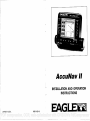
AccuNav II
INSTALLATION AND OPERATION
INSTRUCTIONS
LITHO IN U.S.A.
988-0129-18
EAGI
PDF compression, OCR, web-optimization with CVISION's PdfCompressor
NOTES:
WARNING!
USE THIS GPS RECEIVER ONLY AS AN AID TO NAVIGATION. A
CAREFUL NAVIGATOR NEVER RELIES ON ONLY ONE METHOD TO
OBTAIN POSITION INFORMATION.
CAUTION
This GPS receiver, (like all GPS navigation equipment) will show the
shortest, mostdirect path to a waypoint. It provides navigation datato the
waypoint regardless of obstructions. Therefore, the prudent navigator will
not only takeadvantage ofall available navigation toolswhentravelling to
awaypoint, butwill also visually check to make certain aclear, safepath to
the waypoint is always available.
NOTICE!
As of this writing, the Department of Defense (DOD) has not declared the
GPS navigation system operational. The system is still in a testing phase.
Satellites canbetumedofforaccuracycan bedegraded atwillbythesystem
operators. Remember thatthe AccuNav II, or anyGPSreceiveris only as
accurateas the systei it's using.
Copyright0 1993 EagleElectronics
All rightsreserved.
All featuresand specifications subjectto change withoutnotice.
All screens in this manual are simulated.
PDF compression, OCR, web-optimization with CVISION's PdfCompressor
Mp
I
MI
I
012
I
B
MI
I
006
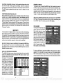
TABLE OF CONTENTS
•:jj?IIlfl[eI
(ii
INSTALLATION
POWER CONNECTIONS
GPS MODULE INSTALLATION
KEYBOARD
N
,pj4n,u,Ipumópip,p'In,,,,I'
:
GPS-HOWITWORKS
7
ACCURACY
THEEAGLE GPSMODULE
GETTING STARTED INITIALIZATION
CHANGE POSITION
CHANGEALTITUDE
CHANGE TIME
CHANGEDATE
COLD START
POSITION/NAVIGATION DISPLAYS
SATELLITE INFORMATION SCREEN
POSITION SCREEN
STEERING SCREEN
NAVIGATION SCREEN
CUSTOMIZE SCREENS
PLOTTER
PLOTTER CURSOR
PLOTTING WITH AWAYPOINT
PLOTTER MENUS
PLOTTER MENU . PAGE1
CLEAR PLOT
SETRANGE
ICON ON/OFF
ALARMS
GOTO CURSOR
CHANGE DISPLAY
PLOTTER MENU - PAGE2
SELECT UNITS OF MEASURE
BACK LIGHT ON/OFF
GRID LINES
PLOTTER UPDATE
EVENT MARKER
USING THE EVENT MARKER WITH THECURSOR
ERASING ICONS
HELP
WINDOWS
VIEWING WINDOWS OPTIONS
WAYPOINT NAVIGATION
HOWTO SAVE AWAYPOINT
QUICKSAVE METHOD
VIEWANDSAVE METHOD
ENTER NEWWAYPOINT
NAMEAWAYPOINT
ERASE A WAYPOINT
RECALL AWAYPOINT
ROUTES
CREATING A ROUTE
S
S
-
HH:MM:SS
00:00:20
GROUP "H"
NAMEAROUTE
WAYPOINT SELECTION
FOLLOWING A ROUTE
CANCEL NAVIGATION
MODIFYING A ROUTE
ERASING A ROUTE
GPSALARMS
ARRIVAL ALARM
XTE (CROSS TRACK ERROR) ALARM
ANCHOR ALARM
CHANGING GPSSETTINGS
46
1
2
3
6
9
10
10
10
11
II
12
12
13
14
15
15
16
17
17
IS
IS
IS
19
19
19
19
20
20
20
21
21
22
22
22
23
23
24
25
25
26
26
26
27
27
28
28
29
29
30
30
31
32
32
33
33
35
35
35
35
PDF compression, OCR, web-optimization with CVISION's PdfCompressor
TABLE OF CONTENTS (cant.)
SELECT NMENDGPS RECEIVER
TRUEANDMAGNETIC POSITION
PRESET
MAN OVERBOARD
PCFOFFSET
OPS MODULE SELF-TEST
GPSSIMULATOR
SPECIFICATIONS
WINDOWS SUMMARY
36
38
39
39
41
'13
c
44
45
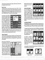
WINDOWS SUMMARY
All of the window groups Used by the
ACCUNaVII are shown on the following
pages. To view these groups, simply
press the WINDOWS key, then repeated press the downarrow key. This
will "cycle" the unit through all groups.
GROUP "A"
rcUEHENT POSITIOFf]
36°08.987'
— 950 50 559'
N
U
:
DIe
I
MPH
S
I
F*L.t*'4tiJj
'c"
"B"
I
{{11t
N'
J..i,
S
1MI
MI
I
A ''I,,,,,,A,,,,,,I,,,i,,A
I
a
U
,,,,o',,,,,I,,,,,i ''i,,
N
I
2800
I
010
I
MI
U
NI
''''A,,,,,,l,,,i,,
aA,,,,,,I,,,,,,A
U
I
,,,iM,,,iiI,'n,,
N
a
0.26 FAEL
GROUP "E"
GROUP "D"
BRG
FIPII
22.O
a
0.29
fl
GROUP
N
E
u
('I
PII
UI'u''Ain"I ,,,i,il
N
A',,,',I,',,,,,,I,,,,'
'.i.4u.iu
22.0 LE.L
GROUP
IMI
S
1111
rni4Ii ni
IDie
N
U
'A,,',,'I,,,,,,A,,,,,,
I
E
W
MI
__
_______
Lull
.4
GROUP"G"
GROUP"F"
45
PDF compression, OCR, web-optimization with CVISION's PdfCompressor
AccuNav II GPS RECEIVER SPECIFICATIONS
GPS Module Dimensions
2.5"H x 4.1W x 7" D
Channels
Five Parallel
Four continuous for position
All satellites in viewtracked
rate
One second
Update
Accuracy
PositionS
Velocity
Maximum accuracy achievable with
Standard Positioning Service
25 meters CEP
0.25 meters/sec RMS
Without SA PDOP<6.0
NMEA 0183 SENTENCES
Minimum Recommended Sentence, Part B
RMB
Minimum Recommended Sentence, Part C
RMC
Present Position - Latitude/Longitude
OLL
APB
Autopilot Steering Data
INTRODUCTION
The AccuNavII is a high quality, wide screen GPS receiverwith performance that is second to none in its class. Using menu featuresand "softkey"operation, the AccuNav II is also one oftheeasiest-to-use products
Eagle has ever built. Thewide "Ultravision" screen shows the navigation
and plotter screens with high resolution and detail. The display and
keyboard are also lighted for nightoperation. This unitis also differential
GPS (DGPS) ready for superioraccuracy.
Read this manual and takeit with youthe firstfewtimesyou useyour unit.
It makes a great reference if you need it.
MOUNTING
Install the AccuNav II in any convenient location, provided there is
clearance behind the unitwhenit is tiltedforthe best viewing angle. Holes
in the bracket base allowwoodscrewor through-bolt mounting. You may
need to placea piece of plywood on the back of thinfiberglass panelsto
secure the mounting hardware. Make certain thereis enough roombehind
the unitto attach the power and OPS module cables.
Thesmallestholethatwillpassone powerorOPSmodule plugisone inch.
Afterthe holeis drilled, passtheOPS cableconnectorupthroughthe hole
first, then passthepowercable downthrough it.
SLOT
Afterthecables havebeen routed, fill the hole with a good marinesealing
compound. Offsetthebrackettocoverthehole.Route the powerandGPS
module cables through the slot in the back of the bracket.
44
PDF compression, OCR, web-optimization with CVISION's PdfCompressor
1
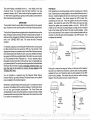
POWER CONNECTIONS
The AccuNavII works from a twelve-volt battery system. For the best
results, attach the power cable directly to the battery. You can attach the
power cable to an accessoryor power buss, however you may have
problems with electrical interference. Therefore, it's saferto goaheadand
attach thepowercabledirectlytothe battery. Ifthecableis tooshort, splice
#18 gaugewire onto it. The power cablehasfour wires; red,black, green,
and white. Red is the positive lead, black is negative or ground. Make
certain toattachthein-linefuseholdertothe red lead as close tothe power
source as possible. For example, ifyouhave to extend the powercableto
thebatteryorpowerbuss, attach one end ofthefuseholderdirectlytothe
batteryor powerbuss. Thiswill protect both the unitand thepowercable
in the eventof a short. The AccuNav II usesa 3-amp fuse.
IMPORTANT!
Do not use this productwithouta 3-amp fusewired into thepowercable!
Failure to use a 3-ampfuse will void your warranty.
TO "P' CONNECTOR
ON ACCUNAV II
WHITE
WIRE
RED
WIRE
TO
3 amp
NMEA
INTERFACE
FUSE
OPS MODULE SELF-TEST
This feature tests the UPS module and returns a special code. Thiscode
is of interest only to the servicedepartment. However, the AccuNav II
interprets this codeand displays astatusmessage. This message is either
"MODULE HAS PASSED" or "MODULE HAS FAILED" and shows at the
bottom of the screen. The current software version numberalso appears
near the bottom of the screen. Contact the factory customer service
department if the module fails the self test. Do not attempt to use this
product if itfails the self test.
To use the self test feature,
presstheMENU keytwicewhile
it'sintheUPSmode, thenpress
thekey nextto the "UPS MODULE SELF TEST" label. The
screen shown at right appears.
To exit fromthis screen, press
the CLEAR key.
P
CPS SELF TEST
BIT SUMMARY
LOW ORDER RAM
HIGH ORDER RAM
PRE PROCESS TEST
PRE PROCESS RAM
MULTI INTERFACE
0000
FFFF
FYFF
0000
FEFF
0000
0000
0000
TEST
SIGNAL INJS
320
0FTWARE_VERSION
CLEARI MODULE HAS PR RED
LICO
GPSSIMULATOR
This feature places position and navigation data on all screens, including
the plotter. The unit "navigates" a closed course. It shows bearing and
distance to go, course over ground, and other information. A recurring
message appears, alerting youthat the simulator mode is enabled. Don't
navigate whenthe simulator is on!
To turn the simulatoron, press the MENU key twice, then press the key
nextto the "UPS SIMULATOR OFF ON" label.The simulator mode starts
immediately. To turn the simulator off, either press and hold the OFFkey
or repeat the above steps. Press thekey nextto the "UPS SIMULATOR
OFF ON" label.
DOPS
BEACON
RECEIVER
AccuNav II POWER CONNECTIONS
2
43
PDF compression, OCR, web-optimization with CVISION's PdfCompressor
is the difference between the
location shown on the present
position display and the position shown on the chart.
Usetherightandleftarrow keys
to move the black box to the
numberthatyou wishtochange
in the latitude, then enter the
numbers.
Position Correction
flflr
flFsET:NIooOO.oOO
MOO'
*I
NUMERIC KEYS
IUSE
TO CHANGE VALUE
UP="N"
DH="S"
Use the up ordown arrow keys
tochange the latitude fromnorthtosouth, ifnecessary. Press the key next
to the "ACCEPT" label when you've entered the desired latitude offset.
Repeat this procedure to
the longitude. In this
CorrjoJ
Factor
Position
example, we have entered .012
degrees northlattitudeand .068
degrees east longitude as the
PCF offset. That is the difference between the present position shown ontheunitandour
position shown by the chart. In
otherwords, ourpositionshown
on the unit is 0.012 degrees
north and 0.068 degrees east
of the position shown on the
chart.
After you've entered the desired offset, press the key next to the "PCF
OFFSET OFF ON" label. This turns the PCF correction factor that you
entered on. To leave this screen, press the key nextto the "EXIT" label.
Thisreturns the unittothe last usedGPSscreen. It also puts yourchanges
intoeffect.
To turn these changes off, return to this screen and press the key nextto
the "PCF OFFSET OFF ON" label. Remember, Presetting the unit also
erases any PCF offset, thereby turning it off.
The white and green wires are for a NMEA interface and a DOPS
beacon receiver. The AccuNavll sends data to anotherelectronicnavigation devices through the white wire and receives data from a beacon
receiver through the green wire. If the white and green wires are not
used, tape their ends so that they cannot short.
To connect a device to the AccuNav's white or green wires, attach a
shielded, twisted pair cablefrom the device's NMEA intput to the white
wire on the AccuNav It's power cable. Solder the ground conductor of
the twisted pair and the shield to the black wire on thepowercable. Do
not connect the shield to the other device. See the other instrument's
manual for more wiring instructions.
See the NMEA section in this manual for moreinformation.
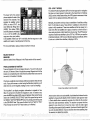
GPS MODULE INSTALLATION
The GPS module can be installed on a flat surface or (with the supplied
adapter) on a pole. Mount the module in an areathat guarantees a clear
view ofthesky at all times. In order forthe module to receive thesignals
from the satellites, it must not be obstructed. An ideal location is on a
cabin roof, or deck. The gunhels also make a good location. Attaching
the pole mounting adapter lets you
install the module on a one inch mast.
5.5mm (7/32")
17mm
However, for lightning protection, the
antenna shoutn't be the highest part
of the boat.
Surface Mounting - With Access
If you have access underneath the
mounting surface, use the gasket
supplied with the OPS module as a
template. Drill four 5.5 mm (7/32")
holes and one 17 mm (11/16") hole
for the module's cable. Attach the
cable to the module and pass it down
throughthe hole in thegasket and the
mounting surface. Use 5 mm
screws, flat washers, and lock washers to fasten the OPS module to the
mounting surface. Route the cable to
theAccuNavII.
(11/16")
Hole
(4 places)
GASKET
5 MM SCREWS
3
PDF compression,42OCR, web-optimization with CVISION's
PdfCompressor
Surface Mounting - Without Access
If you don't have access to the backside of the mounting surface,use
the "cleats" supplied with the AccuNav II. (Note: This is assuming you
can "snake" the module's cable to a location that is accessable. A hole
will still need to be drilled in the mounting surface for the cable.) Using
the gasketas a template, mark and drill the 17mm (11/16") hole for the
cable. Attach the cable to the module and drop the other end of the
cable through the gasket and down the hole. Place the module on the
gasket. Slide the "cleats" onto each end of the module and (using the
cleats as templates) mark four holesfor 5 mm (#10) mounting screws.
Drillthe holes, then replace thecleats on the module and fastenthem to
the mounting surface with 5 mm (#10) screws. Route the cable to the
AccuNavII.
PCFOFFSET
The GPSnavigation system relies on complex mathematical calculations
to determine your position based on satellite data and other factors. One
factor is the Earth's shape. Since the Earth is notatruesphere,variations
in the calculations haveto be made to accommodatedeviations. To make
matters more complex, not everyone uses the same data to determine
whatthe deviations are.Thesizeand shape ofthe ellipsoids that are used
to approximate the earth's surface are improved often. This can lead to
errors if your navigation device uses one ellipsoid,whileyour chart uses
a different one. The term used for theseellipsoids is "Datum."
To reduce theerrorfactorbetween datum, this unitgives youthecapability
to move or "offset"theposition shown on the display to match theone on
thechart. The unitwill add this offsetto all position displays at all times.
Remember, the UPS error is very dynamic and the PCF offset should
never be used in an attempt to cancel the error. In general terms this
featureshould only be usedif your map indicates whatthe possible error
is. Thisfeatureshouldalways be reset to zero (0) whenfinishedwith that
chart.
'CLEAT"
MARK AND
DRILL FOUR
PLACES
For example, suppose you are stopped at a location that is accurately
marked on a chart. Your unit shows a longitude position that is .010
degrees less than the one on the chart. Using the Positipn Correction
Factor (PCF) Offsetfeature, you make the unit readthe same as thechart.
If you move, the unit will continuously add the change to all position
displays. This makes it more closelymatch the datum used by the chart.
For this reason, youshould becareful whenenteringthePCFoffset. This
offset is saved in memory. It doesn't change when the unit is turned off.
However, a Preset does erase the PCFfactor.
To setthePCFfactor, firstpress the MENU key, then press thekey next
GPS
Position Correct ioid
Factor
______________
GASKET
LAT OFFSET: IIJ.tAUJ.UJ.U
______________
LON OFFSET: E 0°OO.000'
to the "CHANGE GPS SETTINGS" label. Now press the
key next to the "ADJUST FCF
OFFSET" label. The screen
shown below appears.
Nowpress the key adjacent to
the "CHANGE OFFSET" label
toenterthe correction factorfor
your location. The screen
shown at the top of the next
CABLE
page appears. Remember,this
4
41
PDF compression, OCR, web-optimization with CVISION's PdfCompressor
The plotter display automatically shows a .1 mile display in the Man
Overboard mode. Your position when the Man Overboard key was
pressedis shown by the "S" with a circle and by the waypoint icon with a
"0" Steertothewaypoint flag to get backto theposition saved whenthe
Man Overboard key was pressed.
IMPORTANT!
The AccuNav II doesn't savethe Man Overboard position inthewaypoint
table. However, it does save theposition on the Man Overboard screen.
TheAccuNav II always shows navigation datatotheposition shown on the
Man Overboard screen whenever the Man Overboard key is pressed. To
stopthe unitfromnavigatingtothe Man Overboard position, press thekey
next to the "DISABLE MOB" label. This resets the Man Overboard
Pole Mount
First, threadthe pole mounting adapter onto the mounting pole or ratchet
base. Align the pole mounting adapter so the module will facethe bow of
theboat. Install and tighten the set screw intothe polemounting adapter
and tighten it securely. This should prevent the GPS module from
unscrewing from the pole. Place the gasket onto the pole mounting
adapter. Now attach the cable to the GPS module and pass the cable
through the gasket, pole mounting adapter, and pole. Set the GPS
module on top of the pole mounting adapter and align the four threaded
holes in the module with the holes in the pole mounting adapter. Using
thefour stainless steel 5 mm screws and lock washerssuppliedwith the
AccuNav II, attach the pole mounting adapter to the GPS module. This
completes the assembly.
navigtion.
For example, supposeyouare viewingthePosition screen, andyou press
the Man Overboard key, then press the GPS key. The AccuNav II first
displays then stores your present positionon the Man Overboard screen,
thenswitches backtothePosition screen. Ifyoupress theMan Overboard
key again, itwillstill show navigation datato the position youwerein when
you first pressed the Man Overboard key - not your present position.
Repeated pressingof the Man Overboard key does not repeatedly save
yourpresent position!Theunitonlysavesthe position thefirsttimetheMan
Overboard key is pressed. To save a new Man Overboard postion. you
must first clear the old Dosition by Dressing the key adiacent to the
"DISABLE MOB" label.
You can navigate to a waypoint using the Waypoint Recall feature,
howeverwhen you go backto the Man Overboard screen, the AccuNavll
stops navigating to the recalled waypoint.
Remember, saving thevictimisthe primary goal. Tryall options to rescue
the person immediately afterthe accidenthappens. Training and education are also good accident preventatives. The Coast Guard has
excellentsafetycourses. Instructall members on board yourboaton safety
procedures before leaving thedock. Makecertain all on board knowwhat
to do before any emergency occurs.
POLE
MOUNTING
ADAPTER
SET
SCREW
POLE
If the pole or mast you're using isn't hollow or if the hole in the middleof
the pole is too small for the connectors, usethe cable mounting adapter
suppliedwith your unit.Thread thecable mounting adapterintothe OPS
pole mounting adapter. Then thread the pole into the cable mounting
adapter. Route the cable down the outsideof the pole.
DULE
CABLE
MOUNTING
ADAPTER
CABLE
MOUNTING
ADAPTER
POLE
POLE
PDF compression,40 OCR, web-optimization with CVISION's PdfCompressor
5
KEYBOARD
PRESET
The keyboard haskeys arranged intwo vertical columns plus a horizontal
rowatthebottom. The keys in the leftand right columns are used to enter
numbers, activatethe windows featureand menu selections.. The menu
keyinthebottomrightcomerofthekeyboard activates thefirstmenu page.
The keys along the bottomof the screen are used to activatethe event
markers or man overboard feature, and make menu selections with the
arrow keys.
The Preset featurereturns all sonarand GPSunits to theiroriginalfactory
settings. This resets the units of measure, speakervolume, display
contrast, and more. This doesn't erase anywaypoints or routes, however.
-
WINDOWS This key gives you access to the windows mode, which lets you
customizedisplays.
To presetthe unit, pressthe MENU key until the "PRESET UNIT' label
appears. Pressthekey nexttothatlabel.Themenu screen disappears and
theAccuNavII returns totheGPSposition screen.All unitswill be returned
to their factorysettings.
P05 - Press this key to showthe Position Screen.
PLOT - This key gives access to the Plotter.
NAV - Pressingthis key shows the Navigation Display.
STEER- Press this key to showthe Steering Screen.
MENU- Press this key to show the menus and gainaccessto most functions
WAYPOINT QUICKSAVES Press this keytoinstantly saveyourpresentposition.
WAYPTSAVE - Pressing this key lets you savea waypoint.
WAYPT RECALL- Press this key to recall a waypoint.
ALARM - Usethis key to set the OPSalarms.
CLEAR - This key clears menus and erasesentries from the screen.
EVENT MARKER - To mark a location on the plotter screen,use this feature.
MANOVERBOARD - Pressing this key instantlysavesyour presentpostion and
switchestheunit into amodethatshowsnavigation datatothelast saved position.
ARROW KEYS - These keys are used to make menu selectionsand to move
objects on the screen.
MAN OVERBOARD
One of boating's mostterrifying events is having afriend orfamily member
fall overboard. Thissituation canbe deadly on anybody ofwater,fresh or
salt. It'sparticularly dangerous at night or if you'reout of sight of land. Of
course, the first thing to do is remain calm and try all standard safety
measures to try to rescue the person. If you lose sightof the person, you
can usetheAccuNavII to help start a search pattern.
Onceyou're backat the helm afterinitial rescue effortshavefailed, press
the AccuNav Ii's M4N OVERBOARD key. The screen shown below
appears. Yourpositionatthetimeyoupressed the Man Overboard key is
shown inthe top left cornerof the display. Beneaththe position is thetime
that youpressedthe Man Overboard key. At thebottomof the screen are
the navigation data displays showing the Distance(DTG), Bearing (BRG),
Course (COG), and Time To Go (TTG) backtothe postion atthe top of the
display. Using thesedisplays along with theplotterin thelowerright corner
ofthe displaygives youthe information you need to steerbacktotheman
overboard position.
rrt
36°09.002'
jQiltlN
1'flbJ 9S°OE49'
•
DISABLE
ON - The ON key turns the AccuNav II on.
S:08;58
OFF - Press and HOLD the Off key to turn the AccuNav II off..
r iii
N
0113
BRG
COG
Q43
2390
IU1
IN
113° flj
T1G99:99:991W1
6
AM
39
id.
E
S
PDF compression, OCR, web-optimization with CVISION's PdfCompressor
The lower half of the screen
showsstatistics for each of the
receiver's five channels. This
includes the satellite number
15
13
OK
OK
OK
OK
BAD
01<
OK
OK
OK
OK
OK
OK
OK
OFF
OFF
02
ON
(PRN), its status (STAT), the
ë7
OK
ON
Differential
Error
User
Range
BAD
ON
26
Time
status
(TIME), _______
(UDRE),
and ifSA (SelectiveAvailablity)
CLEAR
_________
_____
is on or off. The UDRE is the
from
range error
your position
to the satellite. Ifthere is an "OK" in this field,then the range errorto that
satellite is 8 meters or less 68 percent of the time.
11
GPS - HOW IT WORKS
The Global Positioning System (GPS) is the bestapproach to navigation
that has ever been devised. Conceived by the Department of Defense
(DOD)andthe United States military,the GPSsystemisan answertotheir
needs of 24 hour global positioning, 365 days a year.
Basically, the system works by using a constellation of satellites orbiting
Earth 11,000miles in space. There will be 21 satellitesin orbit when the
systemis fully operational. Three more satellites will act as spares, for a
total of 24. When all satellites are in place, at least four of them will be in
viewnearlyanywhere on Earthtwenty-four hours a day. The OPS receiver
requires at leastthreesatellites to give a "2D"fix. (A2D fix isyour position
in latitude/longitude. A3Dfixisyourlatitude/longitude plus altitude.) When
it locks on to at leastfour satellites, it displays a 3D fix.
For more information, read your beacon receiver's manual.
SELECTUNITS OF
MEASURE
(See the Select Units of Measure in the Plotter section of this manual.)
TRUE and MAGNETIC POSITION
True and magnetic north are not always the same. True northis thetopof
theworld. It's where all lines of longitude converge. Magnetic north is the
location our compasses point. It lies several hundred miles tothe south of
true north, at a location in Canada.
Charts are usually laid outaccording to a Mercator projectionthat usestrue
north. If you plota course on a chart usingthe Mercator projection, you'll
either haveto convert magnetic readings to true or use true readings.
The AccuNav II can display navigation information in magnetic or true.
When it's turned on for the first time magnetic is used. To switch to true,
press the MENU key whilea GPS screen is displayed. Next, press the key
nextto the"CHANGE GPS SETTINGS" label. Now press thekey nextto
the"SELECT UNITS OF MEASURE"label. Nowsimply press thekey next
to the "BEARING" label. Thismoves the black boxfrom "MAO" to "TRU."
Press the key nextto the "EXIT' label whenyou're finished.
It takes three satellites todetermine
position.
As the receiverlockson toeach satellite, it calculates thedistancefromthe
satellite by measuring the length of timeit takesthe radio signal to reach
it. Each satellite has an extremely accurate clock that tells the receiver
when the radio transmission started. The receivercompares that time
against its own clock, thus it knows how long it took the radio signal
(travelling atthe speed oflightl)to reachit. Ifyouknowtimeandspeed, then
you cancalculate distance. Once you have this fromthree satellites, then
the receivercan determine position.
7
PDF compression, OCR, web-optimization with CVISION's
PdfCompressor
38
ACCURACY
You mayhaveheard talesof extraordinary accuracyfrom GPS receivers.
The DOD requires accuracy of 10 to 15 meters fromthesatellite system.
However, only the military getsthis precision. The way the militarykeeps
us and other unauthorized people fromusingthe moreprecise systemis
coding. In other words, the data coming from thesatellites is encrypted.
Civilian GPSreceivers use"C/A Code." It'saccuracy is intentionallyworse
than the military's "P Code." In this manner, civilian users worldwide can
benefit from excellent position fixes. Meanwhile, the military keeps the
most accurate systemaway from potential enemies. Theoretically, C/A
code can give accurate position fixes up to 15 meters.This is more than
adequate for most people.
However(as of thiswriting), the military isn't satisfied with C/A's potential
accuracy in the hands of the world. So, it's degrading it further with
"SelectiveAvailability" or SA. This is small, random errors intentionally
addedto the system so your accuracy will typicallybe within 100 meters.
Of course, accuracy also depends on the angle of the satellite above the
horizon,signal-to-noise ratio, the number of satellites tracked at one time
(the more the better), and otherfactors. Thesmallest ranges onthe plotter
maynot be usable ifthe SAis high.The present positionsymbolcanmove
offthe screen even whileyou're sitting still.
Don't let this discourage you, however. GPS by nature has much faster
updates thanothersystems (such as Loran), and typicallyis much easier
to use.Accuracy, even with SAon is still better than mostothernavigation
systems. You'vepurchased oneofthefinestnavigatiorrinstruments on the
markettoday. We hope you'll enjoyit for manyyearsto come.
The EAGLEEGP-1 GPS Module
This GPS receiver is currently used in all Eagle GPSreceivers. It'ssmall,
rugged, and fast.The five channel design lets it trackall satellites in view
and acquire up to five satellites at one time. It sends position information
to the AccuNav II once every second. By incorporating Rockwell's GPS
receivertechnology with Eagle's state-of-the-art designand manufacturing capabilities, Eagle brings to theconsumer the mostadvanced line of
GPS marinenavigation systems available in the world.
1'
8
DGPS (Differential GPS) BEACON RECEIVER SETUP
You'll haveto tell the AccuNav II which beacon receiver's data to expect
and set up the parameters forthat data. To do this, first press the MENU
key, then pressthekeynexttothe"CHANGE GPSSETTINGS" label. Now
press the key next to the "SELECT NMEA" label. The screen on the
previous pageappears. Press thekeynext tothedesired beacon receiver.
The beacon receiver is selected, now you'll need to set it up for the
frequencyand bit rate of the station you'll be using in your area.
Repeat the above stepstogetthe NMEA screen as shown on the previous
page. Nowpressthe key nextto the "SETUP BEACON" label. Thescreen
shown belowappears.
The station frequency and bit
rateareshown on the right side
of the screen. Press the key
adjacent to the "INC FREQ" to
increase the station frequency
orthe "DEC FREQ"todecrease
it. Do the samefor the bit rate.
When thestation frequency and
bit rate are adjusted to their
proper settings, press the key
next to the "EXIT" label. The
AccuNav II returns to the last used GPS screen. The letters "DGPS"
appear next to the "POSITION" on all screens that show your present
position, showing that the beacon receiver is working.
To viewthestatus ofthe beaconsignal, presstheMENU key until thefourth
menu pageappears. Nowpressthe key adjacentto the "DIFFERENTIAL
GPS STATUS" label. If the beacon receiver is receiving data from the
transmitterand is connected properly to the AccuNav II, a screensimilar
to the one shown at right appears.
This page showsthe station ID
number, its frequency and bit
rate, the "health" of the station
(0 = best, 5 = worst), signal
strength (the higher the number, the better), andthe signalto-noiseratio (SNR). The highertheSNR number, the better.
pcn
ah1
fl15
fl13
tJ02
It27
26
37
OK
OK
OK
OK
BAD
OK
OK
OK
OK
OK
OK
OK
OK
OK
BAD
OFF
OFF
ON
ON
OH
PDF compression, OCR, web-optimization with CVISION's PdfCompressor
SELECTNMEA
TheAccuNavIIsendsdataoutthewhitewireonthe powercableaccording
to standards set by the NMEA (National Marine Electronics Association).
This allows the AccuNav II to send position, depth, and navigation
information to "listener" units,such aschartinginstruments, autopilots, and
other marine instruments. TheAccuNav II usesthe following NMEA data
protocols: NMEA 0180 and 0183. NMEA 0180 sends steering information
only. It's useful mainly for autopilots. NMEA 0183 sends depth, position,
steering,speed, and more. In order to usethis feature, the whitewire on
the powercable must be connected to the NMEA data inputon the other
instrument. Seetheinstallation section inthefrontof this manual forwiring
connection information.
The AccuNav II also has the
ENTLY
INMEA OFF'MAGNAVOX
USING:
capability to receive differential
data from a beacon receiver.
This gives the unitmuch better
0180
accuracythan normal. However, before purchasing and in- rHFIEA 0183'SlIqRLINK DOPS
stallingabeaconreceiver,make
certain therearetransmitters in
the areayouwishto use. PresSETUP BEAC0N
ently, the AccuNav II can use
the Magnavox MRB-2A or
StarLink MX-50R. Please note that the AccuNav II doesn't send NMEA
0183 data whenthe Magnavox MRB-2A beacon receiver is activated.
?NMEA
F'MAGNAUOD0P3
NMEA SETUP
Once youconnectthe wiring properly,theAccuNav II mustbe told which
NMEA data format to use. Consult the owner's manual of the other
equipment to see which format it needs. Then set the AccuNav II as
follows:
First, press the MENU key. Next, pressthe key nextto the "CHANGE GPS
SETTINGS" label. Now press the key nextto the "SELECT NMEA" label,
The screen shown above appears.
Thedataformat
in useshows atthetop of the screen. Press the
currently
key next to the desired data output. Now press the CLEAR key. The
AccuNav II will return to the last used GPS screen and send NMEA data
out thewhite wire on thepower cable.
GETTING STARTED
Initialization - Power On
In orderfortheAccuNavII to lock ontothesatellites, it mustfirstfindthem.
Ifyousimplyturntheuniton and wait, the unitwill findthe satellites by itself
in 15 minutes orless. Thisiscalled "Cold Start." Ifyoulet itfindthe satellites,
thetime displaywill probably be wrong, since itwill be showing UTC time
orthe timeat Greenwich, England. However, allothernavigation displays,
including the position display will be correct. (Youcan set the timeto your
local time.) To speed upthesatellite acquisition process, you can initialize
the AccuNav II or "tell it where it is" the first time it's turned on. This
initialization process is usually done only once and requires the following
data:
1. Presentposition in latitude/longitude
2. Elevation above sea level (altitude)
3. Today's date and time
Theunitusuallyonlytakesafewminutes or less tofind the satellites once
it's been initialized by the user.
Afterthepowercable andGPSantenna module are installed, press theON
key, then pressthe MENU key. Nowpress the key nextto the "CHANGE
GPSSETTINGS" label. Finally, press the key nextto the "SETLAT,LON,
ALT, TIME, DATE" label.The screen shown below appears next.
This is the GPS setup screen.
The settings now in use are
shown atthe top ofthe display.
If you're using the unitfor the
first time, these settings are
probablywrong for your positionandtime.Tochange anyof
the numbers on this display,
simplypressthe key nexttothe
arrow with the desired label.
For example, to change the
local time, press thekeynextto
the "CHANGE TIME"label.
LATITUDE
LONGITUDE
ALTITUDE
LOCAL TINE
LOCAL DATE
N 36°08.852'
14 9E°SO.484'
1696
10:17:23 PM
1/03'1992_
ELATHAHGEAL
UANGETIMr
DATE
Note: Ifyou don't usethe "cold stari'feature,then youwill haveto change
all ofthesettingson this page to their correctvalues. In otherwords, you
can't simplyenteryour present position and have the unitfindthe correct
values by itself.
9
PDF compression, OCR, web-optimization with CVISION's
PdfCompressor
36
CHANGEPOSITION
Use a chart to determine your position if you don't know it. The latitude!
longitude that youenterdoesn't have to be extremely accurate. Typically,
if you enter a position within one degree of your present position, the
AccuNavII should quickly find your actual latitudeflongitude. To change
your present position, firstpress the key nexttothe"CHANGE LAT" label.
Thescreen shown below appears. Use the downarrow keytochange the
"N" to "5", if necessary. Next,
simplyenter your present latiLATITUDE
N 36008.852?
tude usingthe numbered keys.
LONGITUDE
U 96050.484?
Noticethattheposition entered
ALTITUDE
1696
is in degrees, minutes, and
LOCAL TIME
10:17:23 PM
hundredths of a minute. (Not
LOCAL DATE
1'03'1993
_____________________________
If
make
a
misseconds!) you
take, press the left or right arTO CHANGE LJALUE
row keys to moveto the numUP="N" DN="S"
ber in the latitude that needs
_________________________
changTh Aft rthe latitude
IUE ICKEYSIP
fl
as
nextto the "ACCEPT'label.
LccEPT
Now press the key next to the
"CHANGE LON" label. The black box will be next to the "E" on the
longitude. Again, usethe up or down arrow keys to switchthe "E" to "W"
or west longitude, if necessary. Now enter the longitude using the
numbered keys. Be certain to entera zero "0" as the first number in the
longitude ifit's lessthan 100 degrees!Afteryou'veentered the last number,
press the key next to the "ACCEPT'label.
ARRIVALALARM
The arrival alarm sounds a tone whenyour position is within the alarm's
radius ofa waypoint. For example, the alarm sounds ifyou come within .1
mileofa recalled waypoint ifthe arrival alarm's setting is .1 mile.Thealarm
is adjustable from .01 to 9.9 miles.
XTE ALARM
The XTE (cross track error) alarm sounds a tone when your cross track
error is greaterthan the alarm's setting. Changing the XTE alarm also
changesthe XTE range on thesteering screen. The alarm is adjustable
from 0.0 to 9.9 miles.
ANCHORALARM
Theanchor
alarm sounds atone whenthepresentposition movesoutside
a presetradius. For example, if you settheanchoralarmto .1 nautical mile
(600feet), then the alarm will sound if youmovemorethan 600 feet from
thelocation whereyousetthe alarm. It'sadjustable from0.01 to 9.9miles.
CHANGING GPS SETTINGS
The AccuNav II mustbeinitializedwhenit'sturned onforthe firsttime. This
is described atthebeginning ofthe GPS sectionin this manual. However,
ifyouwishto changeonlyoneof
LATITUDE
N 36°08.852'
theparameters (such as time),
U 95°5O.484'
LONGITUDE
use the menu features in the
ALTITUDE
1696
"CHANGE SETUP" menu. To
LOCAL
TIME
3:27:16
AM
do this, press the MENU key, LOCAL DATE
8'03'2032
then press the key next to the
"CF-lANGE GPS SETTINGS"la-
CHANGE ALTITUDE
To enteryour present altitude, press the key nextto the "CHANGE ALT"
label. The AccuNavII needs to know your elevation abovesea level. (Not
your heightabove the ground.) Again, an approximation is usually sufficient. Use the numbered keys to enter your altitude data. Press the up
arrow key if your altitude is below sealevel. Forexample, suppose you're
in Death Valleyand the spotyou'restanding in is 35 feet below sea level.
You wouldneed to enter the numbers "35", then press the up arrow keyto
changeitto-35feet. Pressthe keynexttothe"ACCEPT" labelwhenyou're
done.
CHANGE TIME
To change the local time (the timeat your position), press the key nextto
the"CHANGE TIME"label. The screen shown atthetop ofthe nextpage
bel. Finally, press the
to
keynext
the "SET LAT, LON, ALT,
TIME, DATE'label. Thescreen
shownbelowappears.
frE
..
'CHANGELATRZflW"ZLT
==
aGE LONJINEM
DATE
Using the menus on this and following menu pages, you canchange the
Initial Position, Time-Date-Time Offset, or Altitude withoutaffecting any
other initialization setting. All of these menus work identically to the ones
described in the initialization section at the beginning of the GPS section.
After you make a change, the unit returns to the GPSor plotterscreen.
You mayneed to re-initializetheunitifyou move a long distance (over100
miles) withtheunitoff. In this exampleyouwould need to entera new initial
position to help the AccuNav II find the correct satellites quicker.
appears.
10
35
PDF compression, OCR, web-optimization with CVISION's PdfCompressor
ARRIVAL_ON OFF
blackboxmoves overthe numbers on the right side. In the
example shown atthetop ofthe
next page, the arrival alarm is
p
<TE
NCH0
Itlil
flF4
selected.
Now pressthe key nextto the
"CHANGE LIMIT" label. The
screen shown below appears.
Thecurrentalarm valueshows
in a windowon thescreen which
I
IT
is
ished.
H
CHANGE
CHANGE DATE
LI1Ij
labled "OLD VALUE"
Use the numbered keys to changethe alarm's setting, then pressthe key
next to the "ACCEPT" labeltoenterit. Forexample, to setthe arrival alarm
to .2 mile, press the 0 key, then
the 2 key, then press the 0 key
NUMERIC KEYS TO
CHANGE VALUE. USE
again. When the desired value
RIGHT ARROW TO
has been entered, press the
key nexttothe "ACCEPT' label.
TheunitreturnstotheALARMS
screen as shown below. Notice
that the alarm has automaticallybeenturned on. Ifan alarm
is off, and you adjust it, the unit
automatically turns it on.
PA
I
1USE
rnLuro.lr
020
Remember,
if you need to set
EPT I
___________
an alarm to less than one (1), entera zero first. For example, to set the
arrival alarm to .5 miles, press the following number keys: 0 5 0.
Nowyou canchange anyother
alarm or press the key next to
the "EXIT" label to leave the
alarm menu.
Use the number keys to enter
the time. Press the up arrow
key to change the time from
AM to PM or the down arrow
key to change from PM to AM.
Press the key next to the "ACCEPT" label when you're fin-
To enter today's date, press
the key nextto the "CHANGE
LATITUDE
LONGITUDE
ALTITUDE
LOCAL TIME
LOCAL DATE
N 36*08.852'
W 95°5O.484'
1696
10:17:23
1/03/1993
WNUMERIC KEYS
L41TO
CHANSE VALUE
'AM"DN'PM"
E>IT IaISACcEPT.
DATE" label. The screen shown below appears. Enterthe date usingthe
numbered keys. When you'refinished, pressthe key "ACCEPT" label.
Thenumbers atthetopofthescreen should becorrect.Iftheyaren't,press
the key next to the label that
LATITUDE
N 36°O8.862'
you need to change. If every1.l 9S°5O.484'
LONGITUDE
thing is correct, press the key
1696
ALTITUDE
next to the "EXIT" label. The
10:17:23
TIME
unit will switch to the position
DATE
1/03/1993
screen and start searching for
KEYS
the satellites currentlyin view.
It should find the satellites and
show a position in a few min-
TMERIC
utes.
COLD START
CUALUE
ACEPT
When the AccuNav II is turned
on for the first time "out of the box", it automatically sends a "cold start"
message tothe GPSreceiver. You also can sendacold startmessage to
the receiver.
If the unit can't lock on to the satellites using thedata you've givenit, or if
it hastroublefinding the satellites, perhaps it is usingthe wrong data. This
can happen if you've entered the wrong data by accident. For example,
given iteastlongitude instead ofwest. Or ifyou've moved a longdistance
with the unitturned off.
You can return to this alarm
screenatanytimeto adjust any
alarm,turnoneoff, orallofthem
on, as desired. Each alarm
worksand adjusts indepentlyof
To senda cold start message to the receiver, pressthe MENU key. Now
press the key nexttothe"CHANGE GPS SETTINGS" label. Finally,press
the key nextto the "GPS "COLD" START" label.The unitwill begin a cold
start technique to find the available satellites. It should lockon to them in
15 minutes or less. Remember, whenit does, your local timeand possibly
theothers. Adescription ofeach
alarm follows.
34
11
PDF compression, OCR, web-optimization with CVISION's PdfCompressor
date display will probably be wrong. Use the method shown above to set
the time and date to their proper local settings. Once this is done, an
internal clockwill keepthe correct time, evenwhen the unitis turned off.
The GPS system updates this clock when the unit is locked on to the
satellites.
POSITION/NAVIGATION DISPLAYS
TheAccuNavII hasa position screen, navigation screen, plotter, steering
indicator, and a satellite information screen. These displays were designedto showthemostimportant data. However, you cancustomize all
of them (except the satellite position screen) to some extentthrough the
"Change Display" feature on the firstGPS menu screen. (There are other
screens that can be customized by using the Windows feature. See the
Windows section for more detail.) To customize these screens, seethe
"Customize" section.
IMPORTANT!
Ifthedatashown in digital numbers on any screen on this unitisflashing,
then it means that data is invalid. Do not rely on that data if it is flashing.
For example, if the position display is flashing, then the unit haslost the
satellites and hasn't re-aquired them. The position that is flashing is your
last known position, notyourpresentposition! Do notnavigatewiththis unit
until you have found the reason the unit has lost the satellites!
Each ofthe following screens is available by firstpressing the MENU key,
then pressing the key next to the desired screen label. A detailed
description ofeachscreen follows. (Press the MENU key twiceto seethe
SatelliteInformation menu.)
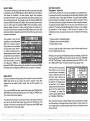
SATELLITEINFORMATION SCREEN
Thesatellite information screen shows technical data about each satellite
in view. The AccuNavII has a five channel GPS receiver. Dataon each
channel is shown at the top of
the display. The channelsare __________________________________
—s
:iau
numberedone throughfive on
13 T 600:31101 35
12 1 s 1 270132401 29
the left side of the screen. Ev'O'2
satellite
in
the
constellation
ery
24 1 T 250?3030t 42
has a number assigned to it,
14 1 T 19°i ?4°T 35
calledthePRN.ThePRNisthe
first number in the channel's
1.69 13 02 06 24
row. TR1C stands for "track." If HOOP
GOOP
3.87
the AccuNav II is trackingthe
POOP
3.33
satellite, then a "T" is placed in TOOP
1.98
thiscolumn. IftheAccuNavllis UDOP
2.87 _____________
.rii
&i
rT 1tjjofl
I
12
ERASINGA ROUTE
To create a route, first press the MENU key. Next, press the key next to
the"More" label.Nowpress thekey nexttothe "ROUTE PLANNING"label.
Route number one appears on the right side of the screen. The list of
waypoints used in the route are shown beneath the route number and
name. If you wish to erase a different route, press the key next to the
"÷RTE" or "-RTE" labels to cyclethrough the available routes.
After you'veselected thedesired route, pressthe key next to the "ERASE
RTE" label. Thiserases the routefrom memory. Finally, press the key next
to the"EXIT" label. This returns you to the GPS display.
GPSALARMS
The AccuNav II hasthreeOPS
alarms. One is an arrival alarm
that sounds when you come
within a preset distance to a
waypoint. The next is a cross
track error alarm that sounds
whenyoumoveoffcourse more
than the alarm's setting. The
lastalarm is an anchor alarm. It
sounds when you move outside of a preset radius. All of
these alarms are set identically.
IU
>TE
AL ON
0.1 0
ON
0.50
:
To adjusta GPSalarm, press the ALARM key. The screen shown above
appears.To turn any alarm on, press the key nextto the desired alarm's
label until the black box moves to "ON", as thescreen belowshows. To
changean alarm's setting, press the key nextto the desired alarm until the
c
"IN
2.1fl
TE.50
.
33
PDF compression, OCR, web-optimization with CVISION's PdfCompressor
IMPORTANT!
Turning the arrival alarm off prevents the AccuNavll from sequencing to
the next waypoint in the route. This, in effect, turnstheroute off. However,
the unitwill still show navigation data to the currentwaypoint in the route
at thetimethearrival alarm was turned off.
searching forthe satellite, then a"S" appears. ELV is theelevation (height)
of the satellite above the horizon from your position. AZM is the azimuth
or direction ofthesatellite fromyour position. For example, iftheazimuth
ofasatellite is 180 degrees, then it is duesouth. SNRisthe signal-to-noise
ratio. Thistells youhow strongthe satellite's signal is. ThehighertheSNR
number, the better.
CANCEL NAVIGATION
To stop the AccuNav II from navigating to waypoint or navigating to a
waypoint in a route, press the MENU key twice. Now press the key next
to the "CANCEL NAVIGATION" label. Thisstops all navigation.
NOTE:
Canceling navigation does not erase the route or any waypoints from
memory. It merelystopsthe AccuNav II from navigating.
MODIFYING A ROUTE
i
Anypartofa route canbechanged at anytime. Forexample, suppose you
have a route consisting of waypoints number 1, 2, and 3 and you wishto
changewaypoint numberatowaypointnumber5. SimplypresstheMENU
key, then press the key nextto the "More" label. Next, press the key next
to the "Route Planning" label. Finally, press the key next to the "Recall
Route" label. Route number one appears on the right side of the screen.
Thelistofwaypoints used in therouteare shown beneaththeroutenumber
and name.
Using
the down arrow key,
movetheblackboxtowaypoint
number 3. Now press the key
to the "CHANGE" label.
Use the numbered keys to
change the waypoint from3 to
next
5. Next, press the key nextto
the "ACCEPT" label. You've
changed thewaypointfrom3to
5. Finally, press thekey nextto
the "EXIT" label and you'refinished.
!
tJSIEL.
—
PIE
RSE
.OUTE it
1
NAME: JPiYS COLJE
1 BUOY 1
2 BUOY2
SANDY PT
Remember, any pad of the route can be changed at any time.
Thesatellites that arevisiblein the skyfromyour position are shown in the
lowerright corner of the screen underthe"VISIBLE SATS" heading.
In the lowerleft cornerof the screen are the DOPS displays. These show
youthe"Dilution Of Precision" (DOP)forthehorizontal (1-IDOP), geometric
(GDOP),position(PDOP),time(TDOP), and vertical (VDOP). The GDOP
is thecombination value of HDOP, VDOP, and TDOP. The smaller the
GDOP'snumber is, the better. The GPSreceiverselects satellites based
on GDOP, thereforeit always tries to usesatellites that have good DOP
values. These depend on the azimuth and elevation of the satellite, and
any ground based obstructions.
Remember, the smallerthe number - the betteron all of the DOPs.
POSITION SCREEN
The position screen automatically appears aftertheAccuNavII is initialized or youcanviewthis screen atanytimeby pressing the PUS key. The
position display shows your present position, course over ground (COG),
crosstrack error (XTE), bearing (BRG), and local time.
Your present position displays near the top of the screen in latitude!
longitude coordinates. This is shown in minutes, and thousandths of a
minute. For example, on this
page,thepresentposition is31
UU
degrees,8.642 minuteslatitude
and 82 degrees, 50.853 min-
utes longitude. Below the
present position ontheleft side
is the Bearing to Waypoint
(BRG) display. This is expressed in degrees true or
magnetic, depending on the
mode the AccuNavII is in. To
the right of the Bearing is the
Course Over Ground (COG)
N
U
36°08.856'
95°50.496'
jOM287OM
_____________
2:S:32
PMHIL
0101
mi
display.
PDF compression, OCR, web-optimization with CVISION's PdfCompressor
32
13
At the bottom of the screen are the Local Time and Cross Track Error
Displays. Pleasenote thatyou must recall a waypoint to use the Bearing
and Cross Track Error displays.
STEERING SCREEN
The steering screen shows a pictorial view of your boat and course
travelled. This is called a Course Deviation Indicator or CDI. It also shows
Distance To Go (DTG), Speed OverGround (SOG), Bearing to Waypoint
(BRG), and Course OverGround(COG). Pressthe STEER keytoviewthis
screen.
Yourpresentposition isshown bythearrow.Thearrowshows thedirection
the boat is heading relative to ________________________________
the waypoint. In theory, if you flu'_______
________
steer the boat with the arrow
_____
_______
always pointing towards the
___________________________
waypoint, thenyouwill arrive at
the waypoint. The solid line ____________________________
extendingfromthe arrow isyour
______________ _____________
track or path you've taken. To
traveldirectlytoawaypoint,try
____________________________
to keep the arrow onthecenter
line. The waypoint is depicted
by a box at the top of the CDI
___________________________N
display. As youapproach the
waypoint, the arrow andthe boxwillmoveclosertogether. Ifyoutravel past
thewaypoint, the waypoint's boxwill move to the bottom of the display.
'in
22.02
___
278° 4 298°
The numbers on the top left side of the screen are distance markers,
showing the remaining distanceto the recalled waypoint. If the numbers
have a blackboxsurrounding them, thenthedistance markers is showing
the distance FAST the waypoint. In other words, if the numbers are
surrounded by a black box, then youhavepassed thewaypoint and need
to turn around.
Thenumbers immediately below the CDIare the CDI range in miles. This
gives you an ideaof how far off course you are. For example, ifthe arrow
is halfwaybetween the course line and the outside left line and the CDI
range is 0.5 miles, then yourcrosstrack erroristo the left 0.25 miles. The
CDI range is thesame as the CDI alarm setting. See thesection on GFS
alarms to change the CDI range.
Using the digital displays at the bottom of the screen with the graphical
14
press the keynextto the "CHANGE" label and enterthe waypoint number
forthe second waypoint in the route. Continue entering thewaypoints until
all of the waypoints havebeen entered for the route. Then press the key
nextto the "EXIT" label. This saves your route in memory.
IMPORTANT!
You must select waypoints in the ordertheyare to be used in the route. In
otherwords, supposeyouwanta route thatconsists ofwaypoint numbers
1, 3, and 5. However, you wishto travel to 3 first,then 1, and finally 5. In
this case,you mustselect waypoint 3, 1, and 5 in that orderwhen making
the route.
FOLLOWING A ROUTE
To follow a route, press the MENU key, then press the key next to the
"More" label. Next, press the key nexttothe"Route Planning" label.Finally,
pressthe key nextto the "Recall Route" label. The screen shown below
appears. Routenumber one appears on the right side of the screen.The
listofwaypoints used in the routeareshown beneath the route numberand
name. If you wish to recall a
different route, press the key
ROUTE
I
+ RTE
WflME: JAYS COVE
next to the "÷RTE" or "-RTE"
labelstocyclethroughtheavailWJPQI.1
—RTE
2BUOY2
able routes.
*
—
Sb%ZZ
3
BUOY 3
After you've selected the de- VERSE
siredroute, you'llnoticeablack
box surrounding the first
waypoint in the route. This is
thestarting waypoint box. Ifyou
wishto startthe routeusing the
firstwaypoint in the route, simply press the key nextto the "START RTE" label. However, if youwishto
start the route using a different waypoint, simply use thedown arrow key
to move the blackboxtothedesired waypoint number. Then press the key
nextto the "STARTRTE' label.
To followa route backwards, press thekey nexttothe"REVERSE"label.
For example, suppose you havethree waypoints in a route and they're
numbered 3,6, and 2. If you travel forwardthroughthe route, the unitwill
shownavigation data towaypoint number 3first,then6, andfinally 2. Ifyou
travelbackward through the route, the unitwill start withwaypoint number
2 first, then 6, and end with waypoint number3. No matter if you travel
forwardor reverse through the route, when you reach the last waypoint in
the route, the arrival alarm sounds until you turn it off.
31
PDF compression, OCR, web-optimization with CVISION's PdfCompressor
This menu lets youselect the route number, name the route, and choose
thewaypoints used in the route.
Namea Route
To assign a name to a route, press the key next to the "-i-RTE"or "-RTE"
labelto move through the list of routes. When the desired route number
appears in the windowatthe top of the screen, press the down arrow key
until the black boxmoves to the "NAME" position. Now pressthe key next
to the "CHANGE" label. The screen shown below appears.
Use the keys on both sides of
thescreen toenterthe waypoint
name. For example, to name a
route"REEF 1", press the number "4" key repeatedly until the
letter "R" appears in the window. Next, press the right arrowkeyto move theblack box
to the next letter position. Now
press the "1" key. The letter "E"
appears onthescreen. Repeat
this process until the entire
name has been written on the screen. Now press the key next to the
"ACCEPT" or "ENTER" label. The AccuNav II returns to the route menu.
You can now enterthe waypoints used in the route.
Waypoint Selection
If you'venamed a route, the black boxshould beon the "0" atthetopofthe
screen. If not, move the black box to the "0" using the up or down arrow
keys. Now press the key nexttothe "CHANGE" label. The screen shown
below appears
Now press the numbered key
of thewaypoint you wishto go
to first in the route. For example, if you want waypoint
number 8to be first,press the 8
key. If you've named the
waypoint, it shows in the blank
spaceto theright ofthewaypoint
number. Next, press the key
next to the "ACCEPT" label.
The cursor should now be on
thesecondwaypointline. Again,
USE
RTE#
6
NUMERIC
NAME
REEF1
KEYS TO
CHANGE
UALUE
U
EXIT
30
..P
0
0
=iACCEP)
display at the top let you accu-
...'.
rately steer the boat to a
-,•I
278 MI
waypoint.
c
22.0MPH
NAVIGATION SCREEN
Use the navigation screen
when you're navigating to a
Mifli
waypoint. It shows your Distance ToGo (DTG), Bearing to
Waypoint (BRG), Local Time,
2:68:19 PHIHIL
MI
Speed Over Ground (SOG),
Course Over Ground (COG),
and Cross Track Error (XTE). To use the navigation screen, first recall a
waypoint, then press the NAV key. A screen similar to the one above
appears.
o5
a9*H
rwqi4ivr
021
rr
CUSTOMIZE SCREENS
Thedigital displays onthe bottom half ofthe Position andSteering screens,
plusall the displays on the Navigation screen canbe changed as desired.
To show how this is done, we'll use the Position screen as an example.
To customizethe PositionScreen, firstpress theMENU key. ThefirstGPS
menu screen appears. Press the key nextto the "CHANGE POSITION
DISPLAY' label. Thd unit returns to the Position Screen
with a black box around the
N
Bearing (BRO) label.
U
The black box identifies the
Bearing box as "ready for
change." To change the Bearing display, press the up or
down arrow keys to select the
displaythat you want to show
inside the box.
36°08.925'
95°50.386'
850
4
197*
H
____________________________
2:69:15 PM1L
0.08 MI
Inthis example, wechangedthe Bearing display to DIG (Distance To Go)
by pressing the up arrow key twice.
h850
NORMAL DISPLAY
DISPLAY READY FOR CHANGE
15
PDF compression, OCR, web-optimization with CVISION's PdfCompressor
=l———
To change anotherdigital display, press the left or right arrow key. The label in the next
digital displaybox changes as
youpressthearrow key. Again,
pressthe up ordownarrow key
N
U
The digital displays available
for use are:
WPTNAME
110
XTE
LOCAL TIME
COG
36° 08856'
95° 50.496'
.
27.8 MIIH 287°
to change thedisplay.
BRG
Bearing
SOG
DTG
DESTWPT
POSITION
ALT
RTE NAME
•ia
PMHIL
0.01
M
MI
Now press the key nextto the
"÷ WPT" or "-WPT" label until
the desired waypoint number
appears onthescreen. When it
does,simplypressthekeynext
to the "GO TO WYAPOINT"
label.TheAccuNavII returnsto
the last used sonar, navigation,
orplotterscreen,showingnavigation datatothe waypoint you
recalled.
Speed OverGround
Distance To Go
Destination Waypoint
Present Position
Altitude
Route Name
Waypoint Name
Time To Go
Cross Track Error
Time at your location
CourseOver Ground
When you have the displayarranged as desired, press the CLEAR key.
This"locks" the display. Every timeyou switch to this display, itwill appear
as you designed it, unless you presetthe unit
PLOTFER
The plotterlets you seeyourcourseand direction oftravelon the screen.
If you've recalled a waypoint, the plotter shows your starting location,
presentposition, and destination. However, you do not have to recall a
waypoint to usethe plotter.
The plotteralso canshowgrid lines on thedisplay. Thesegrid lines show
latitudeand longitude lines that can helpyou visulize your position orthe
location of other objects.
To usethe plotter, simply press the PLOT key. A screen similar to the one
at the top of the nextpage appears.
Theflashingcross is your present position. The solid line is your track, or
path you have just traveled. The large square is a compass rose marked
16
*WPT
1NAME
LJERO BROS
8IL0H
H
hi
jOT8
36009.869'
95037fl'
I....
I
MAUI BAT OH
(MILES)
BRO (MAO)
I h1FO
12S
86°
TUflT
I8EWPT#
ROUTES
Aroutegives you theabilityto navigatetoseveral waypointswithout having
to re-program theunitafterarriving ateach one. A routeconsists oftwoor
morewaypoints. When youtravell on a route, the AccuNavII firstshows
navigation information to the first waypoint in the route. When you reach
thefirstwaypoint,(signalled bytheArrival Alarm), theAccuNav II automaticallysequences to the next waypoint. Navigation information is shown to
thiswaypoint andthe process repeats. Whenyoureach thelast waypoint
in a route, the arrival alarm sounds until you turn it off.
Thereare fourstepsrequired to createand follow a route. First, youmust
createand name the route. Next, select the waypoints used in the route.
Thendetermine the startingwaypoint. Next, tell the unittofollowthe route.
Finally, theunitwillaskyouifyouwishtorun the routeforward orbackward.
After these steps are completed, the AccuNav II will start showing
navigation data to the first waypoint on the route.
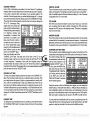
CREATING A ROUTE
To createaroute, firstpressthe
MENU key . Next, press the
key next to the "More" label.
Now press the key nextto the
"ROUTE PLANNING" label.
Finally, press the key next to
the "SAVE/EDIT ROUTE" la-
bel.The screen shown at rightS
appears.
IQUTE#
1
NAME:
—RTE
TE
TE
HG
..
uc::::E:E
::::::g:::EEEFE-:SE:
::::::g:::E:E:E:EEEEE::
.....9...................
29
PDF compression, OCR, web-optimization with CVISION's PdfCompressor
name. For example, to name a
waypoint "COVE 1", press the
number "0" keyrepeatedly until
the letter "C" appears in the
window. Next, press the right
arrow key to move the black
box to the next letter position.
Now press the "3" key repeatedly until the "0" appears on
the screen. Repeat this process until the entire name has
beenwritten onthescreen. Now
press the key nextto the "ACCEPT" or "ENTER" label. The AccuNavII
returns tothe waypoint savemenu as shown above. To save thewaypoint
with this name,first press the key nextto the "SAVE" label. Now press the
key nextto the "EXIT" label to exit the waypoint save menu.
Erasea Waypoint
TheWaypoint Erase feature lets you delete waypoints fromthe list.
Toerase awaypoint, firstpress
the WAYPT SAVE key. Now
press the key next to the "-iWPT" or "-WPT" label until the
desired waypoint number ap
pears on the screen. Simply
press the key next to the
"ERASE" label. The screen
_____
BRDG
]NAME I)ERO
N
36°09.869'
t7f1LAT
IL0N 95°37.171'
hi
_____________________________
Sr,tJc
_______________________________
i.su'.....__.naflj
I'
_____ DELETE bJi2iYPOINT
shownatright appears. A mesARE YOU SURE?
_______
sage appears on the screen
that says "WAIT!! DELETE
WAYPOINT ARE YOU LITh
SURE?." If you are certain this
is the waypoint that you wish to erase, press the key next to the "YES"
arrow. If not, press the key nextto the "NO"arrow. Press the key nextto
the "YES" arrow erases all information from the waypoint number that
appears at the top of the screen.
To exit fromthe waypoint save menu, press theCLEAR key.
RECALL A WAYPOINT
You must recall a waypoint in order to navigate to that position with the
AccuNav II. To recall a waypoint, first press the WAYPT RECALL . The
screen shown at the top of the next page appears.
with North, South, East, and
West. The square's height and
width shows at the bottom of
the screen.This is the distance
fromone side to the otherand
fromthetoptothe bottom. Your
present position isshown atthe
top of the screen.
N 36°O8.853'
I
•*Ifl
U
955O.662'
N
22.0
UI
Ifyourpresent position starts to
move outside the square, the
104° I _____________________
S
1111
______
AccuNavll clears the display,
then re-draws your present
position closertothecenterofthescreen. Yourpresentposition will always
be displayed on the plotter.
.,
To clearthe plotterscreen, seethe Plotter Menus section.
On the left side of the screen are the Distance To Go (DTG), Bearing
(BRG), Speed Over Ground (SOG), and Course Over Ground (COG)
digital displays. All ofthesedisplays are used whenawaypointis recalled,
except COG thatis a!ways active. Thesedisplays also canbecustomized.
See the Plotter Menus sectionfor more detail.
PLOTTER CURSOR
The plotter cursor can help you determine the latitude/longitude of a
waypoint oreventmarker. To useit, press the up or down arrow keywhile
the plotteris displayed. A screen similar to theone below appears. Two
new lines appear on the screen. These are the plottercursorlines. Also,
thepresent position displayat thetop of the screen switches to showthe
latitude/longitude position of the plottercursor- not your presentposition.
Usethe arrow keys to move theplottercursorlines to the desired location.
Toerasethecursorlines,press ______________________________
the CLEAR key. This also will
switch the position display at
N
the top of the screen back to •aI
showing your present position.
PLOTTING WITH A
WAYPOINT
Usingthe plotterwitharecalled
waypoint or route is an easy
way to seethe effects of wind
22.0
28°
17
.
.
S
1MI
PDF compression, OCR, web-optimization with CVISION's PdfCompressor
28
andcurrentonyourboat. Italso
1
N 36°09.037' U 95%0408' J
simplifies navigation. To use L
the plotter in this manner, first
DTEi
N
jul
recallawaypointorstartaroute.
(SeetheWaypointRecallsectionformoreinformation.) Then
r fl:
press the PLOT key. A screen
similar to the one at right appears.
f
fl:
'bpij
—l.
r'706
-:1
a.
E
The "5" is your starting locaS
2M1
____
tion. This was your position
whenyourecalledthewaypoint.
The flashingcircle with a cross is your present position. The "flag" with a
number inside is the destination (recalled waypoint). The number inside
the flagisthe recalled waypoint number. Inthisexample, waypoint number
10 is the destination. The dotted line is the shortest, most direct course
from the starting point to the destination. Follow this line to get to the
waypoint.
An arrival alarm canbe settosound atonewhenyoucome withinapreset
distance tothedestination. Seethesection onalarms formore information
about the arrival alarm.
PLOTTER MENUS
Pressing the MENU keywhile the plotterdisplays gives youa new set of
menus that relate onlyto the plotter. There are twopages of plottermenus.
PLOTTER MENU- PAGE 1
CLEAR PLOT
To clear or erase the solid track line fromthe screen, usetheClear Plot
menu selection. Theplotterwill
continue to drawyourtrack afterthis key is pressed, starting
from your present position.
SET RANGE
Use this menu to change the
plotter's range or distance
across theplotter'sdisplay. The
rangeis1 statute milewhenthe
PLOT
N.Y
ICON=jIiJ
S
LARNS
—
2MI
GOTO CURSOR.
UANGEOISP
Enter NewWaypoint
To savea location otherthanyourpresent position, firstpress theWAYPT
SAVE key. Using the up and downarrow keys, move the black boxdown
tothe latitude/longitude position. Nowpress the key nexttothe "CHANGE
FIELD" label at the bottom right cornerof the screen. The screen shown
below appears. Use the arrow
keys to change the "N"to a"Sn,
if your latitude is south. Now
NAME
enter the location you wish to
LET N I—°--—.———'
saveusingthenumbered keys.
Use the left arrow key as a
NUMERIC KEYS
SuIiRF
if
make a mis-
1LON
backspace you
_____ TO CHANGE VALUE
take. In otherwords, pressing
UP="N" ON=" 8"
the left arrow key moves the
blackboxover the last number
entered. Notice that the positionentered is in degrees, minutes, and hundredths of a
minute. (Notseconds!) Afteryou'veentered thelatitude, press thekeynext
to the"ACCEPT'label.The waypoint save menu reappears. Next, press
the key nextto the"CHANGE FIELD" label. Press the downarrow key to
switch the longitude from west to east, if necessary. Now enter the
longitude. Make certain to add a zero to the longitude if it's less than 100
degrees. For example, if the longitude is 85 degrees, then enter "085".
Press the keynextto the "ACCEPT" labelwhenyou've finished. Thesave
waypoint menu appears with the position you entered in the waypoint
position boxatthe topofthescreen. Ifthis position is correct, press the key
nextto the "SAVE" label.
LJSE
Name a Waypoint
To assign a name to a waypoint, press the WAYPT SAVE key. The
waypoint savemenu appears. Press the key nexttothe"+WPT" or"-WPT"
labelto move through the list of
waypoints. When the desired
waypoint appears in the window, press the downarrowkey
until theblack boxmovesto the
"NAME' position. Now press
the key next to the "CHANGE
FIELD"label.Thescreen shown
at right appears.
Use the keys on both sides of
thescreento enterthe waypoint
15
27
PDF compression, OCR, web-optimization with CVISION's PdfCompressor
Saving PresentPosition as a Waypoint
(QuickSave Feature)
TheAccuNav II lets yousaveyour present position as awaypoint with only
one key press. This"Quick Save" feature lets youeasilysavethe position
of a wreck or otherlocations.
To save your present position as waypoint, simply press the WAYPT
QUICKSAVE key. TheAccuNavII takes yourpresent position and assigns
the firstavailable waypoint number to it.
Saving PresentPosition - View and Save Method
The"Quick Save" feature doesn't letyou select the waypoint number.You
haveto usethe nextavailable number whenusingthat method. The View
and Save method lets you pick the waypoint number that your present
position is stored in. (Note: You can store a position under a waypoint
number that already hasa position assigned to it using this method.) To
saveyourpresent position, press the WAYPTSAVE key. A screen similar
to the one below appears.
The first waypoint number in
the list appears atthetop ofthe
page. This is the number that
your present position will be
stored under. Your position at
the time you pressed the
WAYPTSAVE key is shown in
AccuNavhis turned on forthe
first time. The available plotter
ranges are.1, .2, .5,1,2,5,10,
20, 50, and 100 miles. Thislets
you"zoomin"toseesmallvariations in your course or "zoom
out" to see your starting position, present position, track,
course, and destination.
ICON ONIOFF
Pressing this key turns on the
iconsthat you placed on thescreen usingthe EVENT MARKER key. For
more information on this feature, seethe Event Marker section.This also
turns on all of the waypoint icons, also.
ALARMS
Pressthis key for the alarms menu. For more information on thealarms,
seetheALARMS section.
GOTO CURSOR
CURRENT
PIJ TION
the "CURRENT POSITION"
boxinthe middleofthe screen.
As previously described, the cursor lines can be used to placean icon or
highhightaposition. When youusethe cursorlines, the position ofthecross
hairson the display are shown atthe top of the screen. Pressing the key
next to the "GOTO CURSOR" label on the plotter menu causes the
AccuNavII toshownavigation and steering data to the positionshown by
thecross hairs. Thisautomatically turns thearrival alarm on, also.
If you wish to savethe location
in the CURRENT POSITION
box under this waypoint number, simply press the key nextto the "USE CURRENT POSITION" label.
Theposition shown in the CURRENT POSITION boxalso will showin the
waypoint location at the top of the screen. To savethe waypoint without
naming it, simply press the key nextto the "SAVE" label.
To use this feature, first move the cursor lines to thedesired locationon
theplotterscreen. Next, press the MENU key. Finally, press thekey next
to the "GOTO CURSOR" label. The unit returns to the plotter screen. A
waypoint flagappears onthe screen (numbered "0") that wasthe location
of thecursorcross hairs when
Tosavethe location underadifferent waypoint number, press the key next
to the "+ WPT" labelto increase thewaypointnumber (i.e. fromwaypoint
number ito 2). Press the key nextto the "- WPT" label to decrease the
waypoint number. Onceyou've decided thewaypoint number to savethe
location under, press the key next to the "USE CURRENT POSITION"
label. Then press the key next to the "SAVE" label. This will store the
location under the waypoint number you selected and return to the last
used position, plot, or navigation screen.
All ofthenavigation displays on
theAccuNav II will show navigation data to the location you
marked. Thisincludes the navi-
you pressed the keynexttothe
"GOTO CURSOR" label.
gation, steering, and plotterdisplays.
Jj••
N
fl:
r
8013
_____
E
BRI3
H
77
COG
II 2700
F
S
2111
PDF compression, OCR, web-optimization with CVISION's PdfCompressor
26
19
CHANGE DISPLAY
The four digital displays on the left side of the plotter screen can be
changedor customized at will. When the AccuNav Ilis first turnedon, or
after it's preset, thefourdigital displays are DistanceTo Go (DTG), Speed
Over Ground (SOG), Bearing to waypoint (BAG), and Course Over
Ground (COG). The available displays that can be placed in these
windowsare: DistanceToGo(DTG), Speed OverGround (SOG), Bearing
towaypoint(BAG), CourseOver Ground (COG), Cross trackerror(XTE),
and Altitude (ALT).
rm
To change anyor all of the digital displays,first press the MENU key while
the plotteris showing. Nowpress the keynexttothe'CHANGEDISPLAY"
label. The unit returns to the plotterscreen with a black box surrounding
the DTG box. This means the
DTG box is ready to be
N 36009.021' 14 9S0S0.S40
changed. Press the left or right
_______________________
arrow key to change the display. For example, to change
700
the Distance To Go to Cross
U
Track Error (XTE), press the
22.0
'
right arrow key four times.
E
r
To change another digital box,
presstheup or down arrowkey
until theflashingbox is on the
desired display. Nowpress the
right or left arrow key until the
340
S
2M1
PLOT'and "GOTO CURSOR". This is
Two of these labels are window menus. Pressing the key
adjacenttoone ofthe "window
menu"labelsgivesyou amenu
with functions that relate only
tothat window. Forexample, if
you press the key adjacent to
the plotter menu label on the
plotter window, the screen will
clear and you will have a new
menu as shown above with
selections such as "CLEAR
the normal plotter menu screen.
To exit froma windowmenu, pressthe CLEAR key.
VIEWING WINDOWS OPTIONS
To seeall of the available windows, press the WINDOWS
key, then press theMENU key.
Now press the key adjacent to
the "MAIN MENU" label.Finally, press the key flext to the
"VIEW ALL WINDOWS" label.
The screen at right appears.
Plotter
YOU MAY SET ANY
desired display appears.
When you have the digital displays customized, press the CLEAR key.
This locksthe screen displays, evenif the unit is turned off and on again.
PLOUER MENU - PAGETWO
SELECTUNITS OF MEASURE
TheAccuNav II candisplay distance in miles, kilometers, or nautical miles,
velocityin miles perhour, kilometers perhour, or knots, bearing in degrees
magnetic or true,Altitudein feet or meters, andtimein 12 houror24 hour
format.
To change anythese, first press the menu key twice. Next, press the key
next to the "SELECT UNITS OF MEASURE" label. The screen shown
below appears. The black box on each line shows the unit of measure
currentlyin use. In the screen shown below, the units of measure are in
20
Thefirstwindowappears in the
PLOTTER PARAMETER
upperright cornerof thescreen.
INDEPENDENTLY FROM MENU.
A description of the screen ______________________________
shows in the boxatthe bottom
of the screen. Now press the key adjacent to the "NEXT" label. This
changes the displayed window and description. When you've finished
viewing the windows, press the CLEAR key.
WAYPOINT NAVIGATION
HOW TO SAVE A WAYPOINT
Waypoints are locations onthe earth'ssurfacethat youwishto go or return
to. Waypoints are useful for marking shipwrecks, hot fishing spots, and
otherfishingor navigation locations. Storing wsypoint's intheAccuNavIi's
memory makes it easyto return to anypoint intheworld bysimplypressing
afew buttons. TheAccuNavIIcanstore upto 200waypoints.Youcanstore
your present position as a waypoint or enter latitudeAongitude positions as
waypointlocations.
25
PDF compression, OCR, web-optimization with CVISION's PdfCompressor
WINDOWS
You can change the displays on the AccuNav II by using the windows
feature. This lets you use different displays to suit your own fishing or
boating situations.The screensavailable in thewindowsmode are divided
intotwo or morewindows per screen. Eachscreen ofwindowsis called a
"group". ThisAccuNavil givesyou 8 differentwindow groups. Group"A"as
shown at right has the plotter,
Course Over Ground, and
'' I,;,t
'
'
steering displays showing in
three separate windows. A
group can have as many as
four windows. A window can
display digital GPSdata, GPS 0.1111
steering ornavigationdisplays,
and many more.
' '' '
'
..-..-.
statute milesfordistance, miles
per hour for velocity, degrees
magnetic forbearing, altitudein
feet, and time is in the 12 hour
format (a.m./p.m.)
Press the key nexttothe unit that
you wishtochange.Forexample,
pressthekey nexttothe Distance
labeltwicetoswitchfrom miles to
kilometers. This moves the black
boxtwo timesfromthe"Ml" tothe
"KM'.
Whenyou havetheunitsofmeasuresetasdesired,pressthekey
nextto the "EXIT' label.
:zJ:!::::::::x:::..'
To use the windows feature,
firstpresstheWINDOWS key.
BACK LIGHT ON/OFF
To turn the back lighting on,
A screen similar to the one
shown at left appears. The
menu at the bottom of the
screenlets youswitchbetween
the"pages" ofdisplays. These
are leftered "A" through "H".
Group "A" shows first. Press
the down arrow key to move
forward through the screens.
Pressthe uparrowkeytomove
backward.
pressthe menu keytwice,then
press the key next to the
"BACK LIGHT" label. This
moves the black box from
"OFF" tothe "ON"position. To
turn the backlights off, repeat
the steps.
GRID LINES
Theplottercan show latitude/longitude grid lines by pressing the key next
to the"GRIDOFF/ON" labelon the second plottermenu page. Totumthe
grid lines off, repeatthe previous step.
For example, pressing the
down arrow key once shows
the group "B" screen . To exit
the windows mode, press the
PLOTTER UPDATE
P03, PLOT, NAV,orSTEER
The plottershowsyourtrackby
drawing asolid line behindyour
present position. The track is
updated once every instantly
when the unit is turned on for
thefirsttime.However, ifyou're
keys. Every one of the group
screens can be modified to
some extent. For example,
press the MENU key while
group "A" is displayed. Four
new labels appear onthe display as shown at right.
24
IN 36°08.967'
r-b13 1—
a:
hi
96°EU.656'
'a
Ui
In
C
—I
r
COG
21
Th.
iiii
PDF compression, OCR, web-optimization with CVISION's PdfCompressor
..
travellinga long distance, the
trackline mayend prematurely
due to the limited number of
- .-.
dotsavailablethat plotthetrack.
Using a longerupdatetimeTo
changethe update rate, press
the MENU key whilethe unit is
10 SECONOS
CURRENT
in theplottermode. Nowpress
UPDATE RATE
the keynext to the PLOT UP- r"cONDS
INSTANT
DATElabel. Thescreen shown
above appears. The available rCLEAR
plotupdate timesareinstant, 2,
5, 10, and 20 seconds. Simply
pressthe keynexttothe desired update time. TheAccuNavII immediately
returns to the plotterscreen using the new time.
NoS3r00.1
th
1U1I MAIT
EVENTMARKER
The AccuNavIl can placeevent markers or "icons"on the plotterto mark
fishing spots, shallow water, or other special locations. There are five
differenticons to choose fromand thereare 100of eachicon for a totalof
500. You can place eachicon individually, however, you haveto erase all
of theiconsin a group.
To placean icon,firstpress the EVENT MARKER key. Thescreen shown
belowappears.
Now selectone of thefive icons shown on the left side of thescreenby
pressing the key next to the
desired icon. As soon as you
Ui 95°EO.709'
press the key, the AccuNav II
places the icon at your present f'O8.888'
position. Thisicon always stays
SELECT MN ICON TO
in this location. It's saved in
PLACE ON PLOTTER.
memory so itwill alwaysshow
onthe display, evenifthe unitis
turned off and on again.
H
•
141°
IDELETE ICON
BANK
itlI
Using the Event Marker with
the Cursor
Normally, whenyouselect an icon, it's placed onthe plotteratyourpresent
position. However, you can place an icon anywhere on the plotter using
22
thecursor. Todothis,firstpress
one of the arrow keys. This
makes the plottercursor lines
appear on the display. Now
move the lines to the desired
l'1pI:l
position on the display by
22.0
N
36°09.061'
hi
96°SO.496'
N
60.7
pressingthe arrow keys. When
it's at the desired location,
press the EVENT MARKER
key, then select an icon. The
AccuNavII places the icon at
the intersection of the plotter
cursor lines.
E
hi
700
S
1MI
To erase thecursor lines, press the CLEAR key.
Erasing the Icons
Although you can place icons on the plotterindividually, you can't erase
them one at a time. You have to erase the whole group of icons. For
example, ifyou'veplace20fish symbol icons, erasing one of themerases
all 20.
To erase anicon,firstpress the
EVENT MARKER key. Next,
press the key nextto the "DELETE ICON BANK' label.The
screen shown belowappears.
Nowselectthe group of icons
thatyouwishtoerase by pressing the key nextto the desired
icon. Afterpressingthekey, the
AccuNav II erases all of the
selected icons from the plotter.
E°°9002'
'
hi
96°SO 389'
?
SELECT AN ICON
1
hiARNING!
J
156°
TO ERASE
FROM PLOTTER.
GROUP
S
1MI
HELP
An extremely usefulfeatureincorporated into the AccuNav II is the Help
menus. Virtuallyeveryfeature has a helpmenu label that, when pressed,
gives one or more pages of text describing how to use that feature. For
example, pressing the MENU key shows thefirstmenu page. A helplabel
also appears onthescreen. Pressingthekey adjacentto thehelplabelgives
you a description of each of the menuitems and howtheywork.
23
PDF compression, OCR, web-optimization with CVISION's PdfCompressor