1
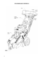
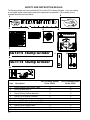
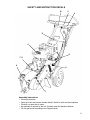
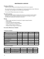
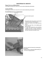
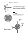
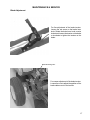
Operator’s And
Parts Manual
MANUAL NO. 8531 REV. 02 (08/12/03)
Models:
SG1114
SG1314
2
CONTENTS
Index
Operator’s Guide Page
Specifications ................................................................................................ 5
Features and Controls .................................................................................. 6
General Information ....................................................................................... 7
Equipment Purpose ....................................................................................... 7
Safety Procedures ......................................................................................... 7
Normal Shutdown Procedure ......................................................................... 9
Emergency Shutdown Procedure .................................................................. 9
Safety and Instruction Decals ........................................................................ 10
Decal Placement ........................................................................................... 11
Assembly Instructions .................................................................................... 11
Operating Instructions
Before You Start ............................................................................................ 12
Operating the Stump Grinder ........................................................................ 12
Operating On Hills ......................................................................................... 13
Transport ....................................................................................................... 13
Maintenance and Service Instructions
Cleaning and Washing .................................................................................. 14
Two minute warning ....................................................................................... 14
Storage .......................................................................................................... 14
Preventative Maintenance Schedule
Inspection Schedule ............................................................................... 14
Lubrication Schedule ............................................................................. 14
Service
Engine Service and Maintenance .......................................................... 15
Cyclone Air Filter .................................................................................... 15
Drive Belt Replacement and Adjustment ................................................ 15
Blade, Pockets and Teeth Removal and Replacement .......................... 16
Brake Adjustment ................................................................................... 17
Wheels Maintenance, Removal and Replacement ................................. 18
Troubleshooting Guide ........................................................................... 19
Unit Assembly and Parts Diagrams ....................................................................... 20-23
General Product Information
Warranty .....................................................................................................24
3
Forward:
Congratulations on the purchase of your new BlueBird equipment!
Your purchase demonstrates trust in the BlueBird name and exemplifies your desire to own durable equipment which is easy to operate and easy to maintain.
To get the full benefit of your purchase, you will need to understand
how to use the controls and many features of your machine. This
operator’s guide has been prepared to assist you in this process.
Please read this guide carefully and familiarize yourself with the basic safety procedures, operating tips, and maintenance information.
Close consideration of the recommendations contained in this
manual will save time, money, and provide years of productivity from
your unit.
As we hope to meet your future needs, please take the time to record
your model and serial number on the back cover of this manual.
This will greatly assist in identification of your model and for future
parts ordering.
4
SPECIFICATIONS
Model
Engine
SG1114
SG1314
11HP Honda w/ cyclone air filter |
13HP Honda w/ cyclone air filter
Length
62'” - 73” (157 185cm) based on handle position
Width
27” (69cm)
Height
24” - 43” (61 - 109cm) based on handle position
Tires
12” knobby 4.10 6
Brakc
Disc type-Lcvcr activated
Drive
Direct
Belt
Gates HiPower Double V Belt BP54
Clutch
Noram Centrifugal Clutch
Cutter Wheel
Teeth
Vertical 14” x 3/8” Disk
8 Tungsten carbide tip teeth w/ pockets
Cutting Depth
Weight
Appr. 12"
249 Ibs (112.9kg)
254 Ibs (115.2kg)
5
FEATURES AND CONTROLS
Bail
Throttle
Handle
Adjustment
Lever
Drive
Cover
Cutting
Wheel
6
On/Off
Switch
Brake
Lever
OPERATOR’S GUIDE
General Information
This owner’s manual has been prepared for the owner and those responsible for the operation of
the BlueBird Stump Grinder. Its
purpose, aside from machine operation, is to promote safety through the use of accepted correct
safety, operating and maintenance
procedures. In order to obtain maximum life and performance from the BlueBird Stump Grinder and
to aid in operating and maintaining
the machine with safety, read the safety, operation and maintenance instructions thoroughly before
operating or servicing the machine
The following safety symbols are used throughout the manual to alert you to information about
unsafe actions or situations:
DANGER indicates immediate hazards that may result in severe injury or death.
WARNING indicates unsafe actions or situations that may cause severe injury, death and/or
major equipment or property damage.
CAUTION indicates unsafe actions or situations that may cause injury, and/or minor
equipment or property damage.
This equipment should not be modified without the manufacturer’s prior written authorization. Doing
so without our written permission may not only affect the equipment’s performance and durability,
but also create safety hazards for the operator and the surroundings. Warranty will be voided if
changes are made to the equipment without the manufacturer’s prior written authorization.
Equipment Purpose
The stump grinder is used to remove tree stumps by progressively grinding pieces of the stump in a
sweeping side to side motion of the
blade across the top and front of the stump.
Safety Procedures (ANSI/OPEI B71.4 1999)
I-Training:
· Read the Operator’s manual. If the operator(s) or mechanic(s) can not read English it is the
owner’s responsibility to explain this material to them.
· Become familiar with the safe operation of the equipment, operator’s controls, and safety signs.
· All operators and mechanics should be trained. The owner is responsible for training the users.
· Never let children or untrained people operate or service the equipment. Local regulations may
restrict the age of the operator.
· The owner/user can prevent and is responsible for accidents or injuries occurring to themselves,
other people or property.
7
OPERATOR’S GUIDE
2-Preparation:
· Wear appropriate clothing including hard hat, safety glasses and ear protection. Long hair, loose
clothing or jewelry may get tangled in moving parts.
· Inspect the area where the equipment is to be used and remove all objects such as rocks, toys and
wire which can be thrown by the machine.
· Use extra care when handling gasoline and other fuels. They are flammable and vapors are
explosive. Use only an approved container. Never remove gas cap or add fuel with engine running.
Allow engine to cool before refueling. Do not smoke. Never refuel or drain the machine indoors.
· Check that operator’s presence controls, safety switches and shields are attached and functioned
properly. Do not operate unless they are functioning properly.
3-Operation:
· Never run an engine in an enclosed area.
· Only operate in good light, keeping away from holes and hidden hazards.
· Be sure all drives are in neutral and parking brake is engaged before starting engine. Only start
engine from the operator’s position.
· Be sure of your footing while using the equipment, especially when backing up. Walk, don’t run.
Never operate on wet grass. Reduced footing could cause slipping.
· Slow down and use extra care on hillsides. Be sure to travel in the recommended direction on
hillsides. Use caution while operating near drop offs.
· Do not change the engine governor setting or overspeed the engine.
· Stop on level ground, stop the blade, disengage drive, engage parking brake and shut off engine
before leaving the operator’s position for any reason.
· Keep hands and feet away from the cutting units.
· Keep pets and bystanders away.
· Do not operate the equipment under the influence of alcohol or drugs.
· Use care and proper lifting technique when loading or unloading the machine into a trailer or truck.
4-Maintenance and Storage:
· Disengage drives, set parking brake, stop engine and disconnect spark plug wire. Wait for all
movement to stop before adjusting, cleaning or repairing.
· Clean grass and debris from cutting units, drives, mufflers, and engine to help prevent fires. Clean
up oil or fuel spillage.
· Let engine cool before storing and do not store near flame.
8
OPERATOR’S GUIDE
· Shut off fuel while storing or transporting. Do not store fuel near flames or drain indoors.
· Park machine on level ground. Never allow untrained personnel to service machine.
· Use jack stands to support components when required.
· Remove spark plug wire before making any repairs.
· Use care when checking blade and teeth. Wear gloves and use caution when servicing.
· Keep hands and feet away from moving parts. If possible, do not make adjustments with the
engine running.
· Keep all parts in good working condition and all hardware tightened. Replace all worn or damaged
decals.
Normal Shutdown Procedure
· Move throttle down to the START/DISENGAGE POSITION
· Wait at least 20 seconds for the blade to stop
· Turn ON/OFF switch to OFF position
· Make sure blade rests on the ground and is at a complete stop before doing anything else
Emergency Shutdown Procedure
· Turn ON/OFF switch to OFF position
· Wait at least 20 seconds for the blade to stop
· Make sure blade rests on the ground and is at a complete stop before doing anything else
9
SAFETY AND INSTRUCTION DECALS
The following decals are found on Model SG1114 and SG1314 Stump Grinders. If any are missing
or not legible, replace them before putting the equipment into operation. Part numbers for the
complete decal kits are listed below.
2
1
4
3
5
6
DANGER
7
SG1314 Stump Grinder
9
10
8
SG1114 Stump Grinder
11
Item
1
2
3
4
5
6
7
8
9
10
11
10
Description
SG1114 Stump Grinder
Kit No. 20236
Decal, BlueBird Logo W/Bird, Large
Decal, BlueBird Bird, 4”
Decal, Caution List
Decal, Warning Carbon Monoxide
Decal, Eye & Hearing Protection
Decal, Danger Foot
Decal, SG1314 Stump Grinder (13 HP)
Decal, SG1114 Stump Grinder (11 HP)
Decal, On/Off Toggle Switch
Decal, Throttle Control
Decal, Handle Adjustment
X
X
X
X
X
X
X
X
X
X
SG1314 Stump Grinder
Kit No. 20238
X
X
X
X
X
X
X
X
X
X
SAFETY AND INSTRUCTION DECALS
10
5
9
11
4
3
7, 8
6
2
1
Assembly Instructions
• Wear eye protection.
• Open top of box and remove wooden blocks. Watch for nails and wood splinters.
• Carefully cut open side of carton.
• No assembly is required on the unit. Carefully read the Operator’s Manual.
• Fill with gas and oil according to the Engine manual.
11
OPERATING INSTRUCTIONS
Before You Start
· Review all the safety decals on the unit
· Wear ear and eye protection
· Be familiar with the safety and shutdown procedures as described earlier in the manual
· Make sure all flaps are in place and in good condition
· Make sure that blade and teeth are in place and in good condition
· Make sure that working area and stump in particular is free of metallic object such as wire, nails,
etc. as such object may be thrown and harm bystanders and damage the equipment.
· Make sure that everyone in the area, including children and animals, are at least 50ft away from
the unit. Debris may be thrown and persons and animals could be harmed.
Operating The Stump Grinder
Warning: Never let the blade touch the ground until it stops rotating.
1.
2.
3.
4.
5.
6.
7.
8.
9.
Place the cutting blade near the right front top edge of the stump.
Set brake to lock position.
Set throttle to (START) DISENGAGE position.
Turn ON/OFF switch to the “ON”.
Start engine.
Allow cold engine to warm up for two minutes at idle before grinding.
Tilt unit on its wheels allowing the cutting wheel to be off the ground.
Move throttle lever to ENGAGE.
Set center of cutting wheel approx. one inch above the top of the stump and one to one
and half inch into the stump.
Note: If cutting wheel is too low, the unit may start to climb over stump and become unstable.
10. Place the cutting wheel into the front top corner of the stump. Swing the cutting wheel side
to side, lowering it approx. one inch before each sweep until the front portion of the stump
has been removed.
11. Before moving the equipment forward, make sure that the cutting wheel is off the ground
and to one side of the stump. Advance machine by releasing brake, push it forward, set
brake again and repeat steps 9 and 10.
12. Repeat steps 9 through 11 until top of stump is removed. Do not cut deeper than ground
level at this stage.
13. Push throttle lever to (START) DISENGAGE position and wait until cutting wheel stops
rotating.
14. Release brake and pull equipment away from stump.
15. It may be necessary to clear the area from wood chips.
16. As you consider cutting deeper than ground level it may become necessary to adjust the
handle position to provide a better hand and arm position while doing so. Pull handle
control lever and adjust handle to the desired position.
17. Repeat steps 6 through 10 until desired depth is achieved.
18. Stop machine when done.
12
OPERATING INSTRUCTIONS
Operating On Hills
Extreme caution must be exercised when grinding stumps on hills as equipment may slide or
move unexpectedly.
Never operate the stump grinder on slopes of 15° or more.
Transport
BlueBird’s Stump Grinder can be transported in the back of a truck, trailer, van or large S.U.Vs. It
features two lifting handles on both sides of the unit to allow two people to lift the unit if necessary.
Do not attempt to lift the equipment alone. Use safe lifting techniques and do not exceed your
physical limitations.
13
MAINTENANCE & SERVICE
Cleaning and Washing
Regular cleaning, washing and lubricating will prolong the life of your equipment.
Use care with power washers to avoid damage to the warning and operation decals. Watch also
for bearings, chain and engine and avoid direct spray to these items.
Do not exceed 1000 psi water pressure for cleaning.
Two minute warning
Stump grinder may be tipped for cleaning and access for no more than 2 minutes. Engine
damage may result from gasoline draining into the crankcase if prolonged. See engine
manufacturer’s operating and maintenance instructions.
Storage
• Refer to engine manufacturer’s instructions for engine storage information.
• Clean machine.
• Cover all scratches with touch up paint.
• Lubricate according to Lubrication Schedule.
• Lightly oil blade and teeth to inhibit rust.
• Covered or indoor storage is recommended.
Preventative Maintenance Schedule
A Inspection Schedule
Item
Out Of Box
Engine oil (Refer to engine manual)
X
Engine air filter (Refer to filter manual)
X
Belt wear and tension
X
Throttle handle and cable
X
Blade and teethwear
X
Fasteners
X
Frame condition
X
ON/OFF switch
X
Decals
X
First 5 Hours
X
X
Every 10 Hours Each Use
X
X
X
X
X
X
X
X
X
B Lubrication Schedule
Item
Engine
Blade bearings
Wheels
14
Lubricant
Oil, see Engine Manual
Chevron SR1 2
Lithium based grease
Every 10 Hours
X
X
As Required
X
X
X
Storage
X
MAINTENANCE & SERVICE
Engine Service and Maintenance
See Engine manufacturer’s manual for service and troubleshooting information.
Cyclone Air Filter
See Engine manufacturer’s manual for service and troubleshooting information.
Drive Belt Replacement and Adjustment
Jack Screw
Cutting shroud Mounting Bolts
1. Disassemble the belt guard by removing the
3 bolts on the face of the belt guard.
2. Loosen the 4 bolts on the cutting shroud as
shown.
3. Loosen the Jam Nuts on the adjusting jack
screws shown.
4 Turn the square head jack screws clockwise
to tighten the belt or counter clockwise to
loosen the belt. Be sure to tighten all nuts and
bolts after adjustment has been made.
Check for proper belt tension by squeezing the
belt together.
The belt should be depressed approximately 1/4”
- 3/4” from its original position.
15
MAINTENANCE & SERVICE
Blade, Pockets and Teeth Removal and Replacement
Roll Pin
Slide bolt through one pocket, through blade section
and through pocket on the other side. Tighten bolts to
120 150 ft lb. Make sure that the roll pins sit against
the back of the pockets. This provides the correct
gauging of the correct gauging of the teeth cutting
edge.
Bolts
WARNING
Cutting teeth may come free of cutting wheel
due to insufficient torque applied to bolts. Be
sure to follow recommended torque settings.
1 Left Tooth
1 Right Tooth
2 Left Teeth
2 Right Teeth
IMPORTANT
When assembling teeth and
pockets to the cutting wheel,
arrange as shown.
1 Left Tooth
1 Right Tooth
16
MAINTENANCE & SERVICE
Blade Adjustment
For fine adjustment of the brake tension.
Loosen the set screw on the brake lever
knob. Rotate the brake lever knob counter
clockwise to loosen the tension on the brake
or clockwise to tighten the tension on the
brake.
Brake mounting nuts.
For coarse adjustment of the brake tension.
Loosen the nuts to adjust the position of the
brake cable mount to the handle.
17
MAINTENANCE & SERVICE
Wheel Maintenance, Removal and Replacement
To remove the left wheel from the Stump Grinder, remove the set collar. Remove 1/4” bolts, 1/4” hex
nuts, springs and brake pad. The wheel is now free to slide off of the axle.
To remove the right wheel, remove the set collar and slide the wheel off the shaft.
18
TROUBLE SHOOTING GUIDE
DANGER
Before servicing unit, wait for all moving parts to come to a complete stop. Turn engine off
and remove the spark plug wire.
Problem
Possible Solutions
Engine will not start
1. Be sure that the kill switch is turned on and the bail (Operator
Presence Control) is actuated against the handle.
2. Check to see that the bail fully actuates the push button switch
on the instrument panel.
3. Check all electrical wires for damage.
Belt coming off
1. Pulleys are not aligned.
2. Belt tension is insufficient. Adjust belt tension.
Belt glazed or slipping
1. Belt tension can be increased using the instructions provided
in this manual.
2. Limit depth of cut.
Pulley is not staying tight
1. Inspect shaft, pulley and key for damage. Be sure that set
screws are tightened properly.
2. Replace any damaged parts.
Cutting wheel is not rotating
1. Engine RPM is not sufficient to actuate centrifugal clutch. Be
sure that the throttle cable is fiunctioning properly.
2. Belt tension is insufficient. Adjust belt tension.
Cutting wheel continues to
rotate
1. Be sure that the throttle lever is moved to the disengage
position.
2. Inspect throttle cable for damage.
3. Check to see that the throttCe cable is assembled to the
engine throttle correctly.
4. Engine RPM is not below 1,800 RPM which will disengage the
centrifugal clutch.
5. Centrifugal clutch is damaged and not disengaging properly.
Replace clutch.
Parking brake slips
1. Adjust brake tension per instructions in this manual.
2. Inspect brake cable and lever for damage.
3. Check to see if the brake pads are worn. Replace if
necessary.
19
ASSEMBLY AND PARTS DIAGRAM
HANDLE AND DECK ASSEMBLY
20
ASSEMBLY AND PARTS DIAGRAM
BELT COVER GUARD ASSEMBLY
CUTTING WHEEL ASSEMBLY
21
Item Part No.
Description
1 ......... 20200 ...........Handle
2 ......... 20201 ...........Bail Assy - includes bail and extension spring (2 ea)
3 ......... 20202 ...........Extension spring (1 ea)
4 ......... 20203 ...........Handle Adjustment Lever Assembly - includes lever, roll pins (2 ea), 1/2" hex
..................................nuts (2 ea)
5 ......... 20204 ...........Handle Adjustment Pin Assembly - includes plate, 1/2" adjustment pin (2 ea),
..................................1/4" bolts (2 ea), 1/4" flat washer (2 ea), 1/4" lock washers (2 ea), #10 bolt (2
..................................ea), #10 washer (4 ea), #10 lock nut (2 ea), compression spring (2 ea)
6 ......... 20205 ...........Brake Lever - includes lever, 5/16"-18 x 2 3/4" hex bolt (2 ea), 5/16 flat
..................................washer (4 ea), 5/16"-18 lock nut (2 ea)
7 ......... 20206 ...........Brake Cable
8 ......... 20207 ...........Brake Caliper Assembly - includes caliper assembly, 1/4"-20 lock nut (2 ea),
..................................1/4" washer (2 ea)
9 ......... 20208 ...........Throttle Cable Assembly - includes throttle assembly with knob, #10-24 x 3/4"
..................................slotted round head screw (2 ea), #10-24 lock nut (2 ea), #10 flat washer (2 ea)
10 ....... 20209 ...........On/Off Toggle Switch - includes switch, boot cover and hardware
11 ....... 20210 ...........Plunger Switch Assembly - includes switch, #10-24 x 3/4" slotted round head
..................................screw (2 ea), #10-24 lock nut (2 ea), #10 flat washer (2ea)
12 ....... 20211 ............Wire Harness Assembly
13 ....... 20212 ...........Drive Cover Assembly - includes cover, 3/8"-16 x 5/8" hex bolt (3 ea), 3/8"
..................................lockwasher (3 ea) 3/8" flat washer (3 ea)
14 ....... 20213 ...........Belt Guard Plate - includes plate, 3/8"-16 x 5/8" hex bolt (1 ea), 3/8"-16 x 1" hex
..................................bolt (2 ea), 5/16"-24 x 1 1/4" hex bolt (4 ea), 3/8" lock washer (3 ea), 3/8" flat
..................................washer (6 ea), 1/4" flat washer (12 ea), 1/4" lock washer (4 ea), 3/8"-16 x 1" set
..................................screw (3 ea), 3/8"-16 x 1 3/4" coupler nut (3 ea), 3/8"-16 x 1 1/8" coupler nut (3 ea)
15 ....... 20214 ...........Centrifugal Clutch Assembly - includes 2-groove centrifugal clutch B-4" OD,
..................................3/8-24 X 1 1/2" hex bolt (1 ea), 3/8” split lock washer (1 ea), 3/8" flat washer
..................................(1 ea), 1/2" flat washer (1 ea), 1/4" sq x 2" key (1 ea)
16 ....... 20215 ...........Double V-Pulley - includes B-3.55" OD V-pulley, 1/4" square x 2" key (1 ea)
17 ....... 20216 ...........Right Wheel - 12" short hub wheel, set collar 3/4" bore
18 ....... 20217 ...........Left Wheel - 12" wheel with disc brake, set collar 3/4" bore
19 ....... 20218 ...........Axle Assembly - Axle 3/4" diameter, 1/4-20 x 1 1/4" hex bolt (1 ea), 1/4"-20
..................................locknut (1 ea)
20 ....... 20219 ...........Engine Bolt Kit - 3/8"-16 x 1 3/4" carriage bolt (4 ea), 3/8" flat washer (4 ea),
..................................3/8"-16 lock nut (4 ea)
21 ....... 20220 ...........Jack Screw - includes 3/8"-16 x 3" square head set screw (2 ea), 3/8"-16 hex
..................................nut (4 ea)
22
Item
Part No.
Description
22 .......20221 ............. Handle Adjustment Bracket - includes bracket, 3/8"-16 x 1" hex bolt (2 ea), 3/
................................... 8 flat washer (4ea), 3/8" lock nut (2 ea)
23 .......20222 ............. Rear Deflector Kit and Deck Deflector Kit (same P/N for both) - includes
................................... deflector, 5/16"-18 x 3/4" hex bolt (6 ea), 5/16" flat washer (6 ea), 5/16" lock
................................... nut (6 ea)
24 .......20223 ............. Right Side Deflector Kit - includes neoprene deflector, deflector strap, 5/16"................................... 18 x 3/4" hex bolt (5 ea), 5/16" flat washer (5 ea), 5/16" lock nut (5 ea)
25 .......20224 ............. Double V-Belt, BP54
26 .......20225 ............. Cutting Wheel Shroud Kit - includes shroud, 3/8"-16 x 1" hex bolt (4 ea), 3/8"
................................... split lock washer (4 ea) 3/8" flat washer ( 4 ea)
27 .......20226 ............. Bearings, Flange - includes bearing (1 ea), 3/8"-16 x 1 3/4" hex bolt (4 ea), 3/
................................... 8" flat washer (4 ea), 3/8" lock nut (4 ea)
28 .......20227 ............. Cutting Wheel Assembly – (cutting wheel only / no teeth) - 11 1/4" diameter
29 .......20228 ............. Complete Set of Cutting Teeth - includes counter bore pocket (4 ea),
................................... threaded pockets (4 ea), left tooth (4 ea), right tooth (4 ea), socket head
................................... screw (8 ea)
30 .......20229 ............. Right Tooth (1 ea)
31 .......20230 ............. Left Tooth (1 ea)
32 .......20231 ............. Counter Bore Pocket (1 ea)
33 .......20232 ............. Threaded Pocket (1 ea)
34 .......20233 ............. Socket Head Screw (2 ea) - Note: 2 screws are required per complete
................................... pocket)
35 .......20234 ............. Deck, Stump Grinder
36 .......20237 ............. Left Side Deflector Kit – includes neoprene deflector, 5/16”-18 x 3/4” hex bolt
................................... (4 ea), 5/16” flat washer (4 ea), 5/16” lock nut (4 ea)
37 .......20235 ............. SG914 Decal Kit (9 hp) - See page 10 for detail of decals
38 .......20236 ............. SG1114 Decal Kit (11 hp) - See page 10 for detail of decals
23
ONE YEAR LIMITED WARRANTY
For one year from purchase, BlueBird, Inc. will replace for the original purchaser, free of charge, any
part or parts, found upon examination by any Factory Authorized Service Center, or by the Factory at
Beatrice, Nebraska, to be defective in material or workmanship or both.
All transportation charges on parts submitted for replacement under this warranty must be paid by
purchaser.
THERE IS NO OTHER WARRANTY EXPRESSED OR IMPLIED.
Implied warranties, including those of merchantability and fitness for a particular purpose, are limited
to one year from purchase and to the extent permitted by law any and all implied warranties are
excluded. This is the exclusion is permitted by law.
The engines on all units are warranted by the engine manufacturer. Consult Warranty shipped with
each unit. BlueBird, Inc. will not be responsible for any engine claims.
BlueBird, Inc. reserves the right to make changes in design and changes or improvements
upon its products without imposing any obligation upon itself to install the same upon its
products theretofore manufactured.
24
25
P.O. Box 8
Beatrice, Nebraska 68310