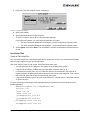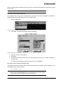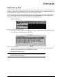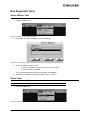
1
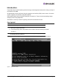
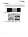
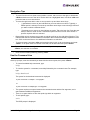
lp6dutil Utility
for LightPulse® Adapters
User Manual
P003639-01A Rev. A
Critical Connectivity Solutions™
Copyright © 2008 Emulex. All rights reserved worldwide. No part of this document may be reproduced by any
means or translated to any electronic medium without the prior written consent of Emulex.
Information furnished by Emulex is believed to be accurate and reliable. However, no responsibility is assumed by
Emulex for its use; or for any infringements of patents or other rights of third parties which may result from its use.
No license is granted by implication or otherwise under any patent, copyright or related rights of Emulex.
Emulex, AutoPilot Installer, BlockGuard, cLAN, FabricStream, FibreSpy, Giganet, HBAnyware, InSpeed, IntraLink,
LightPulse, MultiPulse, SAN Insite, SBOD and Vixel are registered trademarks, and AutoPilot Manager, Critical
Connectivity Solutions, EZPilot, SLI and VMPilot are trademarks of Emulex. All other brand or product names
referenced herein are trademarks or registered trademarks of their respective companies or organizations.
Emulex provides this manual “as is” without any warranty of any kind, either expressed or implied, including but not
limited to the implied warranties of merchantability or fitness for a particular purpose. Emulex may make
improvements and changes to the product described in this manual at any time and without any notice. Emulex
assumes no responsibility for its use, nor for any infringements of patents or other rights of third parties that may
result. Periodic changes are made to information contained herein; although these changes will be incorporated into
new editions of this manual, Emulex disclaims any undertaking to give notice of such changes.
DH-CHAP Notice.
License: Copyright (c) 1998-2006 The OpenSSL Project. All rights reserved. This product includes software
developed by the OpenSSL Project for use in the OpenSSL Toolkit. (http://www.openssl.org/) SSLeay License:
Copyright (C) 1995-1998 Eric Young ([email protected]) All rights reserved. This product includes cryptographic
software written by Eric Young ([email protected]). This product includes software written by Tim Hudson
([email protected]).
Windows DH-CHAP Notice.
Derived from the RSA Data Security, Inc. MD5 Message-Digest Algorithm.
Copyright (C) 1991-2, RSA Data Security, Inc. Created 1991. All rights reserved.
Emulex, 3333 Susan Street
Costa Mesa, CA 92626
lp6dutil Utility Manual for LightPulse Adapters
Page ii
Table of Contents
Introduction............................................................................................................. 1
Start lp6dutil ..................................................................................................... 1
Use the Menu Bar ............................................................................................ 2
Navigation Tips................................................................................................. 2
Use the Command Line.................................................................................... 3
Commands and Syntax Reference Table ........................................................ 4
Reset the Adapter ............................................................................................ 5
Perform a Warm Start ....................................................................................... 6
Exit the lp6dutil Utility ....................................................................................... 6
View Adapter Information ....................................................................................... 7
View Adapter Parameters ................................................................................. 7
View DC Bridge Information ............................................................................. 7
View VPD Information ...................................................................................... 8
View PCI Information........................................................................................ 9
View Revision Information ................................................................................ 9
View Service Parameters ............................................................................... 10
View Counter Information ............................................................................... 11
View Link Status Information .......................................................................... 11
View Link Attention Data ................................................................................ 12
View Wakeup Parameters .............................................................................. 13
View Service Level Interface Memory (SLIM) ................................................. 13
View Mailbox .................................................................................................. 14
View the Registers ......................................................................................... 15
Update Boot Code ................................................................................................ 15
Change the Boot Code State .......................................................................... 15
Load and Update Firmware, Test and Boot Code Files .................................. 16
View and Maintain the Flash Load List ........................................................... 17
View and Maintain Configuration Regions ............................................................ 18
View Configuration Region Information .......................................................... 18
Initialize a Region or Cleaning a Configuration ............................................... 20
Set an Adapter to Use Soft Jumpers .............................................................. 20
Use Script Files ........................................................................................ 21
View the Log File .................................................................................................. 23
Run Diagnostic Tests ............................................................................................ 24
Select HBAs to Test ........................................................................................ 24
Select Tests .................................................................................................... 25
Configure Tests .............................................................................................. 25
Start Tests ...................................................................................................... 26
Set or Reset Status Word Mask ...................................................................... 27
Debug Tasks......................................................................................................... 28
Dump Memory ................................................................................................
Run Program ..................................................................................................
Run Diagnostics .............................................................................................
Try to Recover an Adapter .............................................................................
lp6dutil Utility Manual for LightPulse Adapters
28
29
29
31
Page iii
Introduction
The lp6dutil utility for DOS includes options for doing routine diagnostic tasks and for viewing a variety of
information for the HBA.
All lp6dutil tasks can be performed using the graphical user interface (GUI) screen menus. All screens
require navigation and selection using the keyboard.
Some lp6dutil tasks can be performed using the command line. These include downloading images,
setting up and running diagnostics.
Information in view-only screens is typically presented in hexadecimal format.
Start lp6dutil
Note: You cannot start lp6dutil at the DOS prompt in Windows.
1. Boot up the system with DOS.
2. From the directory where the lp6dutil.exe file resides, enter the following command:
lp6dutil
Note: For debugging, activate the lp6dutil utility without restarting the adapter by entering
the following command: lp6dutil /nr
An Introduction screen appears. A menu bar is near the top. The lp> prompt is near the bottom.
Figure 1: Introduction Screen
lp6dutil Utility Manual for LightPulse Adapters
Page 1
Use the Menu Bar
•
To select a function, press and hold <Alt> and press the letter that is highlighted in the function
title. A menu is displayed. For example, if you hold down <Alt> and press <L>, the Flash menu
is displayed.To move through items within a menu, press the up and down arrow keys. You can
also press the letter that is highlighted for that menu item. In the following example, press <D> to
open the Download Image screen.
Figure 2: Flash Menu, Download Selected
Figure 3: Download Image Screen
lp6dutil Utility Manual for LightPulse Adapters
Page 2
Navigation Tips
•
To move from box to box (area to area) within a screen, tab to move to the right, or hold down
<Shift> and tab to move to the left. If the box title has a highlighted letter, hold down <Alt> and
press the letter to move into the box.
•
To move through items within a box or area, press the up and down arrow keys.
•
( ) parentheses next to an item indicate that you must select one choice. Typically, a
default option is selected. Press the up and down arrow keys to move through choices if
you want to select a different choice.
•
[ ] brackets near or next to an item indicate an option. Tab to the item list. Press the spacebar to select or clear an item. Sometimes optional choices are not active unless a
specific required choice is selected.
•
Boxes within various screens may contain a vertical scroll bar on the right side of the box. This
indicates that the box contains additional information that exceeds the display capabilities of the
box. Click on the scroll bar to view additional information or selections.
•
To select a button, hold down <Alt> and press the letter in red, or tab to the button and press
<Enter>. If an option does not contain a red letter, tab to that button and press <Enter>.
Note: Press <Enter> after selecting an item in a screen. If you do not press
<Enter>, the selection is not made.
•
Close a screen within lp6dutil by pressing <Esc>.
Use the Command Line
At the lp> prompt, enter the command you want with the correct syntax, then press <Enter>.
•
To view all available help commands, type:
help
•
To view the syntax for a command, enter help followed by the command name.For example,
type:
help download
The syntax for the download command is displayed:
Syntax: download <n=adapter> <i=imagepath>
or
Syntax: download <a=adaptertype> <i=imagepath>
•
The syntax requires one space between the command name and the first argument, and a
space between additional arguments.
•
There is no space before or after the equal sign within an argument.
•
To exit lp6dutil, type:
exit
The DOS prompt is displayed.
lp6dutil Utility Manual for LightPulse Adapters
Page 3
Commands and Syntax Reference Table
Note: Internal loopback and static random-access memory (SRAM) tests are not supported
for the LP1005DC-CM2.
Table 1: Commands and Syntax
Command
Syntax
Description
@
@ <command-file>
Executes commands in a script file. Follow
the @ sign with the pathname of the script
file. Example: @a:\script1.txt
enableboot
enableboot <n=adapter> <i=index>
Enables the selected boot code on the
adapter specified by its number.
logfile
logfile <l=filename>
Creates a log file using the specified file
name.
exit
exit
Terminates the lp6dutil session and passes
control to DOS.
jumper
jumper <n=adapter>
<s=selection> <r=region>
Changes the state of the adapter soft
jumpers, which can be used in place of the
physical jumpers on the adapter. s=0 for
none, 1 for hardware default, 2 for soft
jumper. Alternate regions, r= 6 or r=7 (used
only for selection 2, soft jumper).
pciloopback
pciloopback <n=adapter/all> <r=repeatcount> <o=option>
Runs the pciloopback test. You can run this
test on one adapter or on all HBAs in the
system. Options: o=1 for stop, o=2 for repeat,
and o=3 for ignore.
disableboot
disableboot <n=adapter>
Disables the current boot code on the adapter
specified by its number.
extloopback
extloopback <n=adapter/all> <r=repeatcount> <o=option>
Runs the external loopback test. The
loopback plug must be installed. You can run
this test on one adapter or on all HBAs in the
system. Options: o=1 for stop, o=2 for repeat,
and o=3 for ignore.
listhba
listhba
Lists the HBAs that are installed in the system
(adapter #, WWN, functional FW, adapter
type and mailbox error (if any).
reset
reset <n=adapter/all> <s=custom/
standard reset>
Resets one or all HBAs in the system. s=1
skips POST during a restart, s=0 performs a
standard reset.
repeat
repeat <script>
This command is used at the end of a script
file to repeat a series of commands from the
beginning of the script file.
download
download <a=adapter name>
<i=firmware image filename>
Downloads the specified firmware image to all
HBAs of the same name.
download
download <n=adapter number>
<i=firmware image filename>
Downloads the specified firmware image file
to the one adapter, as specified by its number.
lp6dutil Utility Manual for LightPulse Adapters
Page 4
Table 1: Commands and Syntax (Continued)
Command
Syntax
Description
help
help <command>
Lists the syntax for the specified command.
listboot
listboot <n=adapter>
Lists boot code versions with indices (base 1)
that are currently loaded in the flash of the
adapter specified by its number.
vpd
vpd n=<adapter number>
This command displays the VPD contents of
the adapter specified by its number.
Reset the Adapter
1. Select the Adapter menu.
Figure 4: Adapter Menu, Reset Selected
2. Press <R>. The Reset Adapter screen is displayed.
Figure 5: Reset Adapter Screen
3. Select the adapter to reset. The default is adapter #1.
4. Specify the type of reset:
•
Standard is a normal reset.
•
Custom allows you to reset the adapter with one or both of the custom options selected.
•
STUB resets only the functional firmware.
If you select a custom or STUB only reset, the Custom Options area becomes active and you
can specify whether to skip POST or whether to ignore errors. Select one or both options by
pressing the spacebar to select. Press the spacebar again to clear.
5. Select Reset. "Resetting" is displayed briefly.
6. Select Done. The screen closes.
lp6dutil Utility Manual for LightPulse Adapters
Page 5
Perform a Warm Start
1. Select the Adapter menu.
Figure 6: Adapter Menu, Warmstart/NoRam Selected
2. Press <W>. The Warmstart Adapter screen is displayed.
Figure 7: Warmstart Adapter Screen
3. Specify a type of warm start:
•
Warmstart Mode accesses the RAM.
•
NORAM Mode does not access RAM.
•
Restart causes the adapter to start in warm start mode and then restart normally.
4. Proceed to initiate the warm start.
5. Select Done to close the screen.
Exit the lp6dutil Utility
To exit lp6dutil:
1. Select the File menu.
Figure 8: File Menu, Exit Selected
2. Press <X>. The lp6dutil session is terminated and the DOS prompt appears.
lp6dutil Utility Manual for LightPulse Adapters
Page 6
View Adapter Information
View Adapter Parameters
To display a list of HBAs installed in the system, including adapter model number and device ID, from the
Adapter menu:
1. Select the Adapter menu.
Figure 9: Adapter Menu, Display Selected
2. Press <D>. The Installed Adapter Parameters screen is displayed.
Figure 10: Installed Adapter Parameters Screen
3. Select an HBA in the Adapters box. Information is displayed in the Adapter Info box. This
information is view-only.
4. Select OK to close the screen.
Note: A HS20 Blade can have one adapter and two ports (appears as a 1005DC HBA). A
HS40 Blade can have two HBAs or two ports (appears as two 1005DC HBAs).
View DC Bridge Information
1. Select the Adapter menu.
Figure 11: Adapter Menu, DC Bridges Selected
lp6dutil Utility Manual for LightPulse Adapters
Page 7
2. Press <B>. The Dual Channel Bridges screen is displayed.
Figure 12: Dual Channel Bridges Screen
3. Select an adapter in the Adapters box. Adapter information is displayed in the Information box.
4. Select OK to close the screen.
View VPD Information
1. Select the Adapter menu.
Figure 13: Adapter Menu, VPD Selected
2. Press <V>. The Adapters VPD screen is displayed.
Figure 14: Adapter VPD Screen
3. Select an adapter in the Adapters box. The adapter's VPD information is displayed in the VPD
box.
4. Select OK to close the screen.
lp6dutil Utility Manual for LightPulse Adapters
Page 8
View PCI Information
1. Select the Info menu.
Figure 15: Info Menu, PCI Info Selected
2. Press <P>. The PCI Parameters screen is displayed.
Figure 16: PCI Parameters Screen
3. Select an adapter in the Adapters box. PCI information is displayed in the PCI Info box.
4. Select OK to close the screen.
View Revision Information
1. Select the Info menu.
Figure 17: Info Menu, Revisions Selected
lp6dutil Utility Manual for LightPulse Adapters
Page 9
2. Press <R>. The Revisions Info screen is displayed.
Figure 18: Revisions Info Screen
3. Select an adapter in the Adapters box. Revision information is displayed in the Rev Info box.
4. Select OK to close the screen.
View Service Parameters
1. Select the Info menu.
Figure 19: Info Menu, Service Parameters Selected
2. Press <S>. The Service Parameters screen is displayed.
Figure 20: Service Parameters Screen
3. Select an adapter in the Adapters box. Service parameters are displayed in the Service
Parameters box.
4. Select OK to close the screen.
lp6dutil Utility Manual for LightPulse Adapters
Page 10
View Counter Information
1. Select the Info menu.
Figure 21: Info Menu, Counters Selected
2. Press <C> The Counters Display screen appears.
Figure 22: Counters Display Screen
3. Select an adapter in the Adapters box. Counter information is displayed in the Counters Info
box.
4. To set the counters to zero for all fields, select Clear.
5. Select Done to close the screen.
View Link Status Information
1.
Select the Info menu.
Figure 23: Info Menu, Link Status Selected
lp6dutil Utility Manual for LightPulse Adapters
Page 11
2. Press <L>. The Link Status screen is displayed.
Figure 24: Link Status Screen
3. Select an adapter in the Adapters box. Link status information is displayed in the Link Status
box.
4. Select OK to close the screen.
View Link Attention Data
5. Select the Info menu.
Figure 25: Info Menu
6. Press <A>. The Link Attention Data screen is displayed.
Figure 26: The Link Attention Data Screen
7. Select an adapter in the Adapters box. Link attention data is displayed in the Link Attention box.
8. Select OK to close the screen.
lp6dutil Utility Manual for LightPulse Adapters
Page 12
View Wakeup Parameters
1. Select the Flash menu.
Figure 27: Flash Menu, Wakeup Parms Selected
2. Press <W>. The Wakeup Parameters screen is displayed.
Figure 28: Wakeup Parameters Screen
3. Select an adapter in the Adapters box. Wakeup parameters are displayed in the Parameters
box.
4. Select OK to close the screen.
View Service Level Interface Memory (SLIM)
1. Select the Debug menu.
Figure 29: Debug Menu, SLIM Selected
lp6dutil Utility Manual for LightPulse Adapters
Page 13
2. Press <S>. The SLIM Memory screen is displayed.
Figure 30: SLIM Memory Screen
3. Select an adapter in the Adapters box.
4. Enter values to specify how SLIM is to be displayed:
•
The Offset field represents the starting byte at which information is displayed. An offset
of 0 means information is displayed at the beginning of SLIM. This value is displayed
based on your last session. You can change this value.
•
The Length field represents the number of bits that are displayed.
The contents of the SLIM are displayed in the SLIM Contents box.
5. Select OK to close the screen.
View Mailbox
1. Select the Debug menu.
Figure 31: Debug Menu, Mailbox Selected
2. Press <M>. The Read Mailbox screen is displayed.
Figure 32: Read Mailbox Screen
3. Select an adapter in the Adapter box. The contents of the mailbox are displayed in the Mailbox
Contents box.
4. Select OK to close the screen.
lp6dutil Utility Manual for LightPulse Adapters
Page 14
View the Registers
1. Select the Debug menu.
Figure 33: Debug Menu, Registers Selected
2. Press <R>. The Registers screen is displayed.
Figure 34: Registers Screen
Select an adapter in the Adapters box. Register information is displayed in the Registers box.
•
Host attention corresponds to 31 bits that describe information that the adapter provides to
the host. In Figure 34 the adapter informs the host when a current mailbox command is
finished.
•
Chip attention (also known as port attention) corresponds to how the utility gets the
adapter's attention. For the example, the utility informs the adapter when a pending Mailbox
Attention command has an error.
•
Host status corresponds to errors and events.
•
Host control corresponds to the driver utility.
3. Select OK to close the screen.
lp6dutil Utility Manual for LightPulse Adapters
Page 15
Update Boot Code
Change the Boot Code State
This procedure allows you to enable or disable boot code (if x86 BootBIOS or OpenBoot is installed).
1. Select the Flash menu.
Figure 35: Flash Menu, Boot Bios Selected
2. Press <B>. The Change Boot BIOS State screen is displayed.
Figure 36: Boot Code Disabled
3. Select an adapter in the Adapters box.
4. Select the boot code image in the BIOS Images list.
5. Select Change. The boot code is enabled or disabled for the selected adapter. In the following
example, the boot code is enabled.
Figure 37: Boot BIOS Enabled
6. Select OK to close the screen.
Note: The Change Boot BIOS State screen is used to enable or disable the boot code. For
x86 BootBIOS, you must also enable the adapter to boot from the SAN using the
BIOS utility.
lp6dutil Utility Manual for LightPulse Adapters
Page 16
Load and Update Firmware, Test and Boot Code Files
You can load and update files and images to one or more HBAs using the menu bar. You can also load
and update files using the utility that was loaded with the driver.
1. Select the Flash menu.
Figure 38: Flash Menu, Download Selected
2. Press <D>. The Download Image screen is displayed.
Figure 39: Download Image Screen
3. Select the location of the image file and the adapter to be updated.
4. Select the Reset After Download setting.
•
Defaults to Yes. If you are updating a single file to one adapter, keep the default setting.
•
If you are updating several HBAs or several files to one adapter, select No.
5. Select OK. The screen closes and the load process begins. Various steps of the download
process are displayed. When the download is finished, the results of the download (success or
error) are displayed.
lp6dutil Utility Manual for LightPulse Adapters
Page 17
View and Maintain the Flash Load List
The flash load list enables you to view or delete the images that have been installed on the adapter.
To view the flash load list:
1. Select the Flash menu.
Figure 40: Flash Menu, Display Flash Selected
2. Press <F>. The Flash Load List screen is displayed.
Figure 41: Flash Load List Screen
3. Select the adapter. The flash load list Information is displayed for the selected adapter.
4. Select Done to close the screen.
To delete an image from the adapter:
1. Display the flash load list and select an adapter.
2. Select the image you want to delete.
3. Select Delete.
A warning screen is displayed. On the warning screen, select Delete to delete the file, or Cancel
to close the warning screen and cancel the delete.The image selected in the Images box is
deleted.
4. Select Done to close the screen.
lp6dutil Utility Manual for LightPulse Adapters
Page 18
View and Maintain Configuration Regions
View Configuration Region Information
1. Select the Flash menu.
Figure 42: Flash Menu, Configuration Regions Selected
2. Press <C>. The Configuration Regions screen is displayed.
Figure 43: Configuration Regions Screen
3. Select the adapter and corresponding region.
Region Specifics •
Region 1 represents Node A configuration
•
Region 2 represents Node B configuration
•
Region 3 represents Node C configuration
•
Region 4 represents the wakeup parameters
•
Region 5 represents the default PCI configuration
•
Region 6 represents the download 1 (on the Soft Jumpers screen, PCI Alt-1)
•
Region 7 represents the download 2 (on the Soft Jumpers screen, PCI Alt-2)
Select Cleanup to clear the first 4 bytes of the specified configuration region in flash so that this
region can be programmed.
4. Enter values in the Hex Input area to specify the configuration region:
•
The Offset field represents the starting byte at which information is displayed. An offset
of 0 means information is displayed at the beginning of the region. The value displayed
is based on your last session. You can change this value.
•
The Length field represents the number of bits that are displayed.
For example, if you set the Offset value to 100 and the Length field to 100, information for the
selected region is displayed beginning at byte 100 and continuing through the next 100 bytes.
lp6dutil Utility Manual for LightPulse Adapters
Page 19
5. Select Read. Region information is displayed in the Region Data box.
Figure 44: Configuration Regions Screen with Information
6. Select Done to close the screen, or proceed to initializing or cleaning a region.
Initialize a Region or Cleaning a Configuration
1. After you have viewed configuration region information and determined that you want to initialize
a region or clean a configuration, make sure the adapter and region are selected in the
Configuration Regions screen.
On the Configuration Regions screen, select Init. The Init Region screen is displayed.
Figure 45: Init Region Screen
2. To initialize, select Init Region.
3. After the configuration is initialized, you can clean the configuration. Select Clean Config.
4. Select Done to close the screen.
Set an Adapter to Use Soft Jumpers
You can change the state of the adapter soft jumpers, which can be used in place of the physical
jumpers on the adapter.
1. Select the Flash menu.
Figure 46: Flash Menu, Soft Jumpers Selected
lp6dutil Utility Manual for LightPulse Adapters
Page 20
2. Press <J>. The Soft Jumpers screen is displayed.
Figure 47: Soft Jumpers Screen
3. Specify the adapter.
4. Specify Hardware Default or Soft Jumpers.
To select or clear an option, tab to it and press the spacebar.
If you select soft jumpers, you must select an alternate PCI region.
•
PCI Alt-1 represents Download 1 and Region 6 on the Configuration Regions screen.
•
PCI Alt-2 represents Download 2 and Region 7 on the Configuration Regions screen.
5. Select Update, then select Done. The information is updated on the adapter and the screen is
closed.
Use Script Files
Create or Edit Script Files
You can create script files to download images and run scripts from one file. You can download firmware
and boot code images from the Input Script screen.
Use a text editor to create or edit scripts. Script files follow these rules:
•
You can run scripts on one adapter in the system or on all HBAs in the system.
•
n represents the number of HBAs and may equal either a numeric value or all.
•
r represents the repeat count. You can cause the series of all commands in the script file to
repeat indefinitely by adding the repeat command as the last line of the script file. If you include
this command, press <s> to stop a running script at any time.
•
o represents the action option if an error is encountered. 1= stop the test, 2= repeat the test and
3= ignore the error.
For your convenience, this sample script (samplescript.txt) is included in the same directory as the
lp6dutil application:
download a=lp8000 i=c:\temp\dd381a3.awc;
reset n=1 s=0
;reset n=2 s=0
;reset n=all s=0
;pciloopback n=1 r=10 o=1
;pciloopback n=2 r=10 o=2
pciloopback n=all r=50 o=3
extloopback n=all r=40 o=3
lp6dutil Utility Manual for LightPulse Adapters
Page 21
Copy this sample script and modify it to fit your needs. Commented lines begin with a semicolon and are
not executed.
Note: All script files end with .txt.
Run Script Files from the Menu Bar
Use the Select Input Script screen to select and run script files. The results are logged in an output file
named lp6dlog.txt and are displayed in the Test Logfile screen.
1. Select the File menu.
Figure 48: File Menu, Open Input Script Selected
2. Press <O>. The Select Input Script screen is displayed.
Figure 49: Select Input Script Screen
3. Select the location of the script file.
4. Select OK.
5. The Select Input Script screen closes. All scripts listed in the file are run. Results are logged in
the output file.
To close the screen without selecting an input script, select Cancel.
Run Script Files Using the Command Line
Use the @ command to run scripts files. In the following example, the script1.txt script residing on the
root directory of the A drive would run:
@a:\script1.txt
Note: You can view results (log files) with a text editor by opening the lp6dlog.txt file
(always saved in c:\lp6dutil\lp6dlog.txt), or by using the menu bar. You can change
the name and location of the log file using the command line.
lp6dutil Utility Manual for LightPulse Adapters
Page 22
View the Log File
After you have run input scripts, view the test results in the Test Logfile screen. These test results are
logged in an output file named lp6dlog.txt. This file is automatically placed in the c:\lp6dutil directory. The
system appends the lp6dlog.txt file as tests are run and results are logged.
To save the test results and ensure that future test results are logged, copy and rename the lp6dlog.txt
file. The lp6dlog.txt file has a limited scrolling buffer size of approximately 12 screens. Copying and
renaming the .txt file helps you to avoid accumulating a large lp6dlog.txt file.
1. Select the File menu.
Figure 50: File Menu, Read Logfile Selected
2. Press <L>. The Test Logfile screen is displayed. Figure 51 below contains tips for using the log
file, rather than an example of the log file itself.
Figure 51: Test Logfile Screen
The most recent test results are displayed at the bottom of the screen. Use the up and down
arrows on your keyboard to scroll through the test results.
3. Select OK. The screen closes.
Note: You can always view test results using a Text Editor. After you copy and rename the
log file however, you cannot view the file in the Test Logfile screen. Renamed log files
must be viewed using a text editor.
lp6dutil Utility Manual for LightPulse Adapters
Page 23
Run Diagnostic Tests
Select HBAs to Test
1. Select the Test menu.
Figure 52: Test Menu, Select Adapters Selected
2. Press <A>. The Select Adapters screen is displayed.
Figure 53: Select Adapters Screen
3. Select the HBAs you want to test.
•
To select one adapter, press the up and down arrow keys.
•
To select all HBAs, select All.
To close the screen without selecting any HBAs, select None.
4. Select OK. The HBAs are selected and the screen is closed.
Select Tests
Note: Internal loopback and SRAM tests are not supported for the LP1005DC-CM2 adapter.
1. Select the Test menu.
Figure 54: Test Menu, Select Tests Selected
lp6dutil Utility Manual for LightPulse Adapters
Page 24
2. Press <T>. The Select Tests screen is displayed.
Figure 55: Select Tests Screen
3. Select the tests you want to perform on the HBAs.
•
To move through the test list, press <Tab>.
•
To select a test, move to the [ ] field for the test and press the spacebar or <Enter>.
•
To select all tests within a box, select All.
•
To clear all tests (de-select all tests), select None.
To close the screen without selecting any tests, select Cancel.
4. To confirm your options, select OK. Tests are now selected and the screen is closed.
Configure Tests
Note: Internal loopback and SRAM tests are not supported for the LP1005DC-CM2 adapter.
1. Select the Test menu.
Figure 56: Test Menu, Select Options Selected
2. Press <O>. The Configure Test Parameters screen is displayed.
Figure 57: Configure Test Parameters Screen
3. Select the test to configure. Press <Tab> to select the Test Specific Options box. Press the up
and down arrows keys to select the test you want to configure.
lp6dutil Utility Manual for LightPulse Adapters
Page 25
4. If you want the selected test to be repeated if an error is encountered, specify a value in the
Repeat Count field. The repeat count defaults to the last value entered in this field. To change
this value, tab to the Repeat Count field and press <Backspace> to clear the necessary fields.
Enter the new value. To repeat the tests indefinitely, set the count to 0.
5. To change the error action, tab to the Error Action list. Press the up and down arrow keys to select
an error action:
•
Stop - stops the test if an error is encountered. This is the default error action.
•
Repeat - runs the failed test again.
•
Ignore - ignores the error.
6. To confirm your options, select Done.
To cancel out of this screen, press <Esc>.
Start Tests
1. After you have configured the tests, select Start Tests from the Test menu.
Figure 58: Test Menu, Start Tests Selected
2. The Test Results screen is displayed.
Figure 59: Test Results Screen
3. Select Start. All tests are run on all HBAs in the Under Tests box. As applicable, test result
messages are displayed in the Messages box.
To interrupt a test while it is running, select Stop
When all tests are finished, select Done. The screen is closed.
Set or Reset Status Word Mask
The Set/Reset Status Word Bits screen allows you to test the adapter's behavior in various modes.
lp6dutil Utility Manual for LightPulse Adapters
Page 26
1. Select the Adapter menu.
Figure 60: Adapter Menu, Set Status Word Selected
2. Press S. The Set/Reset Status Word Bits screen is displayed.
Figure 61: Set/Reset Status Word Bits Screen
3. Select the adapter to test. The default is adapter #1.
4. Select the status and mask bits. Tab to the bit and press the spacebar to select or clear it. To
close the screen without changes, select Done.
5. Select Set, then select Done. The bits you have selected are set and the screen is closed.
Debug Tasks
Dump Memory
1. Select the Debug menu.
Figure 62: Debug Menu, Dump Selected
lp6dutil Utility Manual for LightPulse Adapters
Page 27
2. Press <D>. A warning screen is displayed.
Figure 63: Dump Memory Warning Screen
3. To continue with the memory dump, on the Warning screen select OK. To close the Warning
screen without dumping memory, select Cancel.
4. The Dump Memory screen is displayed.
Figure 64: Dump Memory Screen
5. Select an adapter in the Adapters box.
6. Enter values in the Hex Input area to set up the memory dump:
•
The Adr field represents the starting address.
•
The Len field represents the number of bytes.
7. Select Dump. The memory contents are displayed.
8. Select OK to close the screen.
Run Program
The Run Program screen allows you to run firmware test programs, if the firmware test images have
been downloaded. The test results are also displayed in this screen.
1. Select the Debug menu.
Figure 65: Debug Menu, Run Program Selected
lp6dutil Utility Manual for LightPulse Adapters
Page 28
2. Press <P>. The Run Program screen is displayed.
Figure 66: Run Program Screen
3. Select an adapter in the Adapter box.
4. Tab to the Program ID Word 1 field. Press <Backspace> to clear the necessary fields. Enter the
firmware test program name.
5. Select Start. Test results display in the Result box.
6. Select Done to close the screen.
Run Diagnostics
•
Four standard tests can be run using the Test menu (see “Run Diagnostics” on page 29). The
Run Diags screen allows you to run customized tests that must be downloaded to the adapter.
Instructions for creating customized tests are beyond the scope of this manual.
•
To download customized tests, use the same procedure for downloading other files and images
(see “Load and Update Firmware, Test and Boot Code Files” on page 17).
The Run Diags screen allows you to run up to five tests at one time.
1. After starting lp6dutil, Select the Debug menu.
Figure 67: Debug Menu, Run Diag Selected
lp6dutil Utility Manual for LightPulse Adapters
Page 29
2. Press <I>. The Run Diags screen is displayed.
Figure 68: Run Diags Screen
3. Select an adapter in the Adapter box.
4. Specify values in the Select Common Parameters area. To change a value, tab to the field, and
press <Backspace> to clear the field.
•
Repeat Count •
•
•
Display Option - A binary code that determines the message information that is printed
in ASCII format to a serial port.
•
•
•
•
0 = Test loops indefinitely until the test is stopped manually.
X = Enter any other number to indicate the number of times you want tests to be
repeated. If more than one test is specified, you cannot stop a test until all tests
are completed.
00 = No information is printed.
1F = All information is printed.
03 = Minimal information is printed.
Request Type •
•
1 = Only one test can be run.
2 = Multiple tests (up to five) can be run.
•
Entry Count - The number of tests to be run.
•
Error Action •
•
•
•
•
Stop = Test is stopped if an error is encountered.
Ignore = Errors are ignored during testing.
Repeat = If an error is encountered, the test is rerun.
Loop = If an error is encountered, all tests are rerun.
Select Parameters for - This field allows you to access a Parameters Selection screen
for the selected test. If multiple tests are downloaded, a down arrow is displayed on the
right side of this box. A separate Parameters Selection screen is displayed for each test.
lp6dutil Utility Manual for LightPulse Adapters
Page 30
Parameters Selection screen a. Enter values in this screen for the following custom test parameters:
• Version
• Program ID
• Revision Compatibility
• Subtest 3
• Subtest 2
• Subtest 1
• Subtest Selection
b. Select OK on the Parameters Selection screen to set up the test. The screen is closed.
5. On the Run Diags screen, select Start. Results are displayed in the Test Results box. If multiple
tests have run, a vertical scroll bar is displayed on the right side of the box. This indicates that
the box contains additional test results that exceed the display capabilities of the box. Click on
the scroll bar to view additional test results.
6. Select Done to close the screen.
Try to Recover an Adapter
If the adapter cannot be reset, the Try to Recover screen allows you to attempt recovery.
1. Select the Debug menu.
Figure 69: Debug Menu, Recovery Selected
2. Press <E>. All HBAs that are active in the system are displayed in the Try to Recover screen:
Figure 70: Try To Recover Screen
3. Select an adapter to recover.
4. Select Proceed to attempt recovery or Done to close the screen.
lp6dutil Utility Manual for LightPulse Adapters
Page 31