1
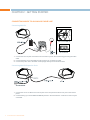
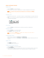
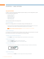
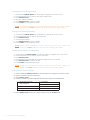
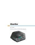
MAX™ EX
INSTALLATION & OPERATION MANUAL
TECHNICAL SUPPORT
Telephone:
Fax:
Email:
Web:
1-800-283-5936 (USA) or
1-801-974-3760
1-801-977-0087
[email protected]
www.clearone.com
MAX EX INSTALLATION & OPERATION MANUAL
CLEARONE PART NO. 800-158-015 SEPTEMBER 2007 (REV 4.0)
U.S. PATENT NO. D499,392. OTHER PATENTS PENDING.
© 2007 ClearOne Communications, Inc. All rights reserved. No part of this document may be reproduced in any
form or by any means without written permission from ClearOne Communications. ClearOne Communications
reserves specific privileges. Information in this document is subject to change without notice.
TABLE OF CONTENTS
CHAPTER 1: INTRODUCTION
1
Service and Support
Product Returns
Unpacking
Important Safety Information
1
1
2
2
CHAPTER 2: GETTING STARTED
Connecting MAX EX to an Analog Phone Line
Connecting MAX EX Expansion Pods
Connecting MAX EX to a Digital (PBX) Phone Line
Using your MAX EX Phone
CHAPTER 3: USER OPTIONS
Calling Features
Programming Features
Alert Tones
CHAPTER 4: MAINTENANCE
Caring for MAX EX Phones
Electrical Considerations
Troubleshooting
CHAPTER 5: APPENDIX
Specifications
Compliance
Warranty
4
4
4
5
6
8
8
9
11
12
12
12
12
14
14
15
18
CHAPTER 1: INTRODUCTION
Thank you for purchasing the ClearOne MAX™ EX expandable conferencing phone. MAX EX provides premium,
full-duplex audio to small conference rooms as a single unit, and to larger rooms by connecting up to four MAX EX
units together. Connecting MAX EX units together allows you to expand microphone and speaker coverage, as well
as control access, for a more natural communications experience in larger rooms.
Setting up the MAX EX conferencing phone is easy and requires only three connections: power, telephone, and
base unit to conference pod. MAX EX’s familiar keypad design ensures users will be comfortable using the phone,
reducing the need for training and support.
Max EX offers these key advantages:
• Expandability: MAX EX is ideal for conference rooms because it provides flexible microphone and
loudspeaker coverage, and easy access to controls, simply by linking units together to match room size.
• Superior Audio Quality: MAX EX delivers industry-leading, crystal-clear audio that facilitates more natural
interactions among conference participants.
• Easy to Use: The MAX EX controls are intuitive, user friendly, and simple to operate.
SERVICE AND SUPPORT
If you need additional information on how to set up or operate your MAX EX conferencing phone, please contact
us. We welcome and encourage your comments so that we can continue to improve our products and serve your
needs.
Technical Support
Sales and Customer Service
Telephone:
Telephone:
Fax:
E-mail:
Web:
1-800-283-5936 (USA) or
1-801-974-3760
1-801-977-0087
[email protected]
www.clearone.com
Fax:
E-mail:
1-800-945-7730 (USA) or
1-801-975-7200
1-800-933-5107 (USA) or
1-801-977-0087
[email protected]
Chapter 1: Introduction
1
PRODUCT RETURNS
All product returns require a return materials authorization (RMA) number. Please contact ClearOne Technical
Support before attempting to return your product. Make sure you return all the items that shipped with your product.
UNPACKING
Ensure you have received all items shown below for your MAX EX model (MAX EX and MAX Expansion Kit). After
unpacking, place the MAX EX Conferencing Pod and Base Unit on a level surface.
MAX EX Package Contents
MAX EX Expansion Kit Package Contents
IMPORTANT SAFETY INFORMATION
Read the safety instructions before using this product. This conferencing phone is not designed for making
emergency telephone calls when the power fails. Make alternative arrangements for access to emergency services.
• Read and understand all instructions.
• Follow all warnings and instructions marked on the product.
• Unplug this product from the wall outlet before cleaning. Use a damp cloth for cleaning. Do not use liquid
cleaners or aerosol cleaners.
• Do not use this product near water, including bathtubs, sinks, or near a swimming pool.
• Do not place this product on an unstable cart, stand, or table.
• Slots and openings in the back or bottom of the product are provided for ventilation. To prevent overheating,
these openings must not be blocked or covered.
• This product should never be placed near or over a radiator or heat register. This product should not used in
built-in installations unless proper ventilation is provided.
2
Technical Services: 800-283-5936
• This product should be operated only from the type of power source indicated on the marking label. If you
are not sure of the type of power supply in your location, consult your dealer or local power company.
• Do not overload wall outlets and extension cords as this can result in the risk of fire or electric shock.
• Never push objects of any kind into this product through cabinet slots as they may touch dangerous voltage
points or short out parts that could result in fire or electric shock.
• Never spill liquids on the product.
• To reduce the risk of electric shock, do not disassemble this product. Opening or removing covers may
expose you to dangerous voltages or other risks. Incorrect reassembly can cause electric shock during
subsequent use.
• Unplug this product from the wall outlet and battery source and refer servicing to qualified service personnel
under the following conditions:
» When the power supply cord or plug is damaged or frayed.
» If liquid has been spilled into the product.
» If the product does not operate normally according to the operating instructions.
» If the product has been dropped or damaged.
» If the product exhibits a distinct change in performance.
• Do not use this product or other phones during an electrical storm. There is a remote risk of electric shock
from lightning.
• Do not use this product to report a gas leak in the vicinity of the leak.
• Do not use this product near intensive care medical equipment or by persons with pacemakers.
• Due to the radio signals between base station and POD, wearers of hearing aids may experience interference
in the form of a humming noise.
• This product can interfere with electrical equipment such as answering machines, TV sets, radios, computers
and microwave ovens if placed too close.
Telephone Wiring and Jack Information
To reduce the risk of fire or injury to persons, read and follow these instructions:
•
•
•
•
Use caution when installing or modifying telephone lines.
Never install telephone wiring during an electrical storm.
Never install telephone jacks in wet locations unless the jack is specifically designed for wet locations.
Never touch un-insulated telephone wires or terminals unless the telephone line is disconnected at the
network interface.
Save These Instructions
Chapter 1: Introduction
3
CHAPTER 2 : GETTING STARTED
CONNECTING MAX EX TO AN ANALOG PHONE LINE
Connecting MAX EX
1. Connect the Link Out jack on the base unit to the Link In jack on the conferencing pod using the CAT-5
cable.
2. Connect the base unit to the telephone jack using the RJ-11 telephone cable.
3. Connect the power cord to the base unit and plug it directly into an electrical outlet.
Connecting MAX EX Expansion Pods
1. Connect the 12' Cat. 5 cable to the Link Out jack on the first phone and the Link In jack on the second
phone.
2. Continue linking up to three additional MAX EX phones in the same fashion. A total of four units may be
connected.
4
Technical Services: 800-283-5936
CONNECTING MAX EX TO A DIGITAL (PBX) PHONE LINE
MAX EX phones can be connected to a PBX by using a digital-to-analog converter. To connect a MAX EX phone to a
digital (PBX) line, use the following diagram and procedure:
1. Connect the telephone cable to the phone jack on the back of the base unit, and the other end into the
digital-to-analog converter.
2. Connect the converter's AC power adapter to an electrical outlet.
3. Connect a second telephone cable from the converter to a digital or PBX phone. Consult the converter’s user
manual for more information.
4. Connect the power cable to the base unit and plug it into an AC outlet.
NOTE: Do not connect the MAX EX phone directly to a digital (PBX) line with out using a digital-toanalog telephone line converter. Permanent damage may result. For assistance, contact
ClearOne technical support.
Chapter 2 : Getting Started
5
USING YOUR MAX EX PHONE
To Make a Call
1. Press the ON/OFF key. You hear a dial tone.
2. Dial the number as you would on a standard phone. The number is displayed on the LCD screen.
NOTE: You can also pre-dial the number while in standby (inactive) mode and press the ON/OFF
key to connect the call. Press and hold the pound key (#) to enter a pause in the dialing
string.
To Answer a Call
1. Press any key (except the star “*” key, MUTE, VOLUME UP or VOLUME DOWN) on the keypad to answer the
call.
2. When there is an incoming call, the phone rings and the LEDs on the phone and the phone icon on the LCD
screen flash (as shown below).
Phone active icon
To End a Call
1. Press the ON/OFF key. This disconnects the call and returns the phone to standby mode.
To Redial a Number
1. Press the ON/OFF key. You will hear a dial tone.
2. Press REDIAL to dial the last number called.
NOTE: You can also press REDIAL while in Standby mode to display the last number called. To
connect the call, press the ON/OFF key.
To Adjust Ringer Volume
• While the phone is ringing, press VOLUME UP or VOLUME DOWN.
• While the phone is inactive, press VOLUME UP or VOLUME DOWN. The ringer melody will play once at the
new level.
To Mute a Call
• Press MUTE to mute the call.
• Press MUTE again to un-mute the call.
To Make a Call Using the Phonebook
1. Press the ON/OFF key. You will hear a dial tone.
2. Press PHONEBOOK.
3. Press the number key (0-9) that corresponds with the location of the stored phone number you want to dial.
This feature must be programmed before use. See Programming Features for additional information.
6
Technical Services: 800-283-5936
To Store a Number In the Phonebook
1. Enter the phone number you want to store while conferencing POD is in standby mode.
2. Press and hold the PHONEBOOK/EDIT key until the phonebook and program icons appear on the LCD
screen (as shown below).
The Phonebook and Program icons.
Adding Phonebook Entries
1. Assign a phonebook location (0–9) by pressing the corresponding number key.
2. Press PHONEBOOK again to save the entry. You will hear a confirmation tone.
3. Press CLEAR to exit phonebook edit mode before saving the entry.
NOTE: Press and hold the 1 numeric key to enter a hyphen or the “*” key to enter a space in the
number. Press CLEAR to delete the old number before entering a new number.
To Access a Speed Dial Number
• Press the SPEED DIAL key. This feature must be programmed before use. See Programming Features for
additional information.
To Access Your Service Center
• While in standby mode, press and hold the “0” key for 2 seconds. This feature must be programmed before
use. See Programming Features for additional information.
Chapter 2 : Getting Started
7
CHAPTER 3 : USER OPTIONS
CALLING FEATURES
In addition to the basic phone operations described in the previous chapter, you can use calling features to perform
any of the following functions during a call:
•
•
•
•
•
Change to Pulse Dialing
Send a Flash Signal
Display a Phone Number
Adjust Speaker Volume
Turn the Ringer On/Off.
These functions are described in the following sections.
To Use Pulse Dialing
MAX EX uses tone dialing by default. You can temporarily change to pulse dialing during a call.
• Press the star (*) key. A special character will appear. All numbers entered after this character will use pulse
dialing. When the call is finished, the dialing mode automatically reverts to tone dialing.
NOTE: When more than 18 characters are entered, a scroll button will appear on the LCD display,
and the numbers will scroll from right to left.
To Send a Flash Signal
If your telephone service includes call transfer, call waiting, conference calling, or other carrier features, use the flash
key to activate the feature. Refer to your local telephone service provider for details.
To Display Your Local Number During a Call
• Press CLEAR. The phone number will appear. After several seconds, the call timer will return.
To Adjust Speaker Volume
• Press the VOLUME UP key while on a call to increase volume.
• Press the VOLUME DOWN key while on a call to decrease volume.
To Turn the Ringer On/Off
• Press and hold the star (*) key. The ringer off icon illuminates when ringer is turned off (as shown below).
Ringer off icon
To Mute During Ringing
• Press the star (*) or the MUTE key to mute the ringer until the incoming call terminates.
8
Technical Services: 800-283-5936
PROGRAMMING FEATURES
To allow for individual preferences and enhanced usability, MAX EX provides the following programmable features:
•
•
•
•
•
•
•
Ringer Melody
Dialing Mode
Flash Duration
Local Phone Number
Speed Dial Numbers
Service Center Number
AGC/ALC (Automatic Gain Control/Automatic Level Control)
You may also restore factory defaults. The following sections describe how to program these features.
Entering Programming Mode
1. Press and hold the REDIAL/PROG key until the program icon appears on the LCD screen (as shown below).
Programming mode icon
To Change Ringer Melody
1.
2.
3.
4.
5.
Press the 1 numeric key to enter the ringer melody menu. There are five available melodies.
Press REDIAL/PROG. The current melody selection will flash.
Press numeric keys 1–5 to play the corresponding melody. The selected melody will play once.
Press REDIAL/PROG to save the selection.
Press CLEAR to exit programming mode.
To Change Dialing Mode
1. Press and hold the REDIAL/PROG key until the program icon appears on the LCD screen.
2. Press the 2 numeric key to enter the dialing mode menu. There are two dialing modes: tone and pulse. The
current dialing mode will be displayed (T for tone, P for pulse).
3. Press REDIAL/PROG. The current mode will flash.
4. Press the 1 numeric key to select tone dialing, or 2 to select pulse dialing.
5. Press REDIAL/PROG to save the selection.
6. Press CLEAR to exit programming mode.
To Change the Flash Duration
1. Press and hold the REDIAL/PROG key until the program icon appears on the LCD screen.
2. Press the 3 numeric key to enter the flash duration menu. The current duration will be displayed in
milliseconds. There are five duration settings: 600, 300, 150, 100 and 80.
3. Press REDIAL/PROG. The current duration will flash.
4. Press the 1–5 numeric keys to select a new duration setting.
5. Press REDIAL/PROG to save the selection.
6. Press CLEAR to exit programming mode.
Chapter 3 : User Options
9
To Program a Local Phone Number
1.
2.
3.
4.
5.
6.
Press and hold REDIAL/PROG until the program icon appears on the LCD screen.
Press the 4 numeric key to enter the user phone number menu.
Press REDIAL/PROG.
Enter the local phone number.
Press REDIAL/PROG to save the number.
Press CLEAR to exit programming mode.
NOTE: Press and hold the 1 numeric key to enter a hyphen. Press the “*” key to enter a space in
the number. Use CLEAR to delete the old number before entering a new number.
To Program a Speed Dial Number
1.
2.
3.
4.
5.
6.
Press and hold REDIAL/PROG until the program icon appears on the LCD screen.
Press the 5 numeric key to enter the speed dial menu.
Press REDIAL/PROG.
Enter the phone number.
Press REDIAL/PROG to save the number.
Press CLEAR to exit programming mode.
NOTE: Press & hold the 1 numeric key to enter a hyphen or the * key to enter a space in the
number. Use CLEAR to delete the old number before entering a new number.
To Program the Service Center Number
1.
2.
3.
4.
5.
6.
Press and hold the REDIAL/PROG key until the program icon appears on the LCD screen.
Press the 6 numeric key to enter the service center menu.
Press REDIAL/PROG.
Enter the number you want MAX EX to dial when the 0 numeric key is pressed.
Press REDIAL/PROG to save the number.
Press CLEAR to exit programming mode.
NOTE: Press & hold the 1 numeric key to enter a hyphen or the * key to enter a space in the
number. Use CLEAR to delete the old number before entering a new number.
To Program the Country Setting
1.
2.
3.
4.
Press and hold the REDIAL/PROG key until the program icon appears on the LCD screen.
Press 7 to enter the service center menu.
Press REDIAL/PROG.
Press the number key that corresponds with desired country from the table below.
1 = US/Canada/China/Japan/
Mexico/Singapore
4 = South Africa
5 = Brazil
2 = Europe CTR21
6 = New Zealand
3 = Australia
7 = South Korea
5. Press REDIAL/PROG to save the country setting, then press CLEAR to exit.
10
Technical Services: 800-283-5936
To Restore Factory Defaults
1.
2.
3.
4.
Press and hold the REDIAL/PROG key until the program icon appears on the LCD screen.
Press and hold the 9 numeric key. The number 8 appears across the LCD screen.
Press REDIAL/PROG to confirm the selection.
Press CLEAR to exit programming mode.
To Program Automatic Gain Control (AGC) and Automatic Level Control (ALC)
1.
2.
3.
4.
Press and hold the REDIAL/PROG key until the program icon appears on the LCD screen.
Press and hold the 8 numeric key. The current AGC setting number appears on the LCD screen.
Press REDIAL/PROG. The current setting number flashes.
Enter a new setting number using the AGC/ALC table shown below.
5. Press REDIAL/PROG to confirm selection.
6. Press CLEAR to exit programming mode.
ALERT TONES
The table below describes alert tones used by MAX EX.
Chapter 3 : User Options
11
CHAPTER 4 : MAINTENANCE
CARING FOR MAX EX PHONES
• Follow all warnings and instructions marked on your MAX EX phone.
• Unplug base unit and conferencing pod from the wall outlet before cleaning.
• Use a damp cloth moistened with water to clean the outside of your conferencing pod or base unit and
power supply. Do not use liquid or aerosol cleaners.
ELECTRICAL CONSIDERATIONS
• Use only the power adapter that comes with your conferencing phone.
TROUBLESHOOTING
If you are having trouble with your MAX EX, it might be configured or connected incorrectly, or other equipment
might be causing the malfunction. Use the following checklist and the chart on the following page to troubleshoot
malfunctions.
Connection Checklist
• The MAX EX base unit is plugged into the proper volt electrical outlet and its power light is on.
•• The telephone cord from the base unit is securely connected to the telephone wall jack.
• The equipment the other party is using should be of comparable quality to your MAX EX conferencing phone.
While MAX EX will work with lower-quality products, the quality of the conference call will be impacted if the
party you are conferencing with has poor quality equipment.
Troubleshooting Table
Use the table on the following page to troubleshoot your MAX EX system.
12
Technical Services: 800-283-5936
Chapter 4 : Maintenance
13
APPENDIX
SPECIFICATIONS
Dimensions (W X D X H)
Phone section: 10.5" x 10.5" x 3"
(26.7 cm x 26.7 cm x 7.6 cm)
Base unit: 4.25" x 5.5" x 2.5"
(10.8 cm x 14 cm x 6.4 cm)
Weight
Phone section: 2.7 lb (1.2 kg)
Base unit: .6 lb (0.27 kg)
Shipping: 10 lb (4.5 kg)
Environmental
Operating Temperature: 0–48° C
(32–118° F)
Storage temperature: 5–70° C
(41–158° F)
Operating Humidity: 15 to 80%
Storage humidity: 10 to 90%
Power
Base Unit:
Auto-adjusting power module;
100–240VAC; 50/60 Hz
Telephone Connection
Analog PBX or PSTN line
RJ-11C/CA11A, –12dBm nominal
Keypad
Alphanumeric standard keypad
Loudspeaker Volume
90 dBspl A weighted @ 1 ft
Bandwidth: 200Hz - 3.3kHz
Record Output
Connector: 2.5 mm mono audio
jack
Impedance: <1000 ohm
Bandwidth: 200Hz–3.3kHz
Dynamic Range: 60dB
THD <.01%
14
Technical Services: 800-283-5936
Echo Cancellation
Tail Time: 128 mS x 3
Noise Cancellation
Dynamic Noise Cancellation
Certifications
FCC Part 15/ICES-003 Class A
FCC Part 68/IC CS-03
CE
UL, C-UL Certified
Warranty
2 Years
Models
MAX EX*
MAX EX Expansion Kit*
*Call your sales representative for part numbers, or visit
www.clearone.com
COMPLIANCE
FCC Part 15/ICES-003 Compliance
This equipment has been tested and found to comply with the limits for a Class A digital device, pursuant to Part 15
of the FCC rules and Industry Canada ICES-003. These limits are designed to provide reasonable protection against
harmful interference when the equipment is operated in a commercial environment. This equipment generates,
uses, and can radiate radio frequency energy and, if not installed and used in accordance with the instruction
manual, may cause harmful interference to radio communications. Operation of this equipment in a residential area
is likely to cause harmful interference, in which case the user will be required to correct the interference at his/her
own expense.
Operation is subject to the following two conditions: (1) This device may not cause interference, and (2) This device
must accept any interference including interference that may cause undesired operation of the device.
Changes or modifications not expressly approved by ClearOne Communications could void the user's authority to
operate the equipment.
FCC Part 68 Compliance
US:FBIMT01B910158015 Ringer Equivalence Number (REN): 0.1B(ac)
This equipment complies with Part 68 of FCC Rules and Technical Requirements for Telephone Terminal Equipment
published by ACTA. The marking on the base unit of this equipment contains, among other information, the US
number and ringer Equivalence Number (REN) for this equipment. If requested, this information must be provided to
your telephone company.
The REN is used to determine the quantity of devices, which may be connected to the telephone line. Excessive
RENs on the telephone line may result in the devices not ringing in response to an incoming call. In most, but not
all areas, the sum of the RENs should not exceed five (5.0). To be certain of the number of devices that may be
connected to the line, as determined by the total RENs, contact the telephone company to obtain the maximum
RENs for the calling area.
If this equipment causes harm to the telephone network, the telephone company will notify you in advance that
temporary discontinuance of service may be required. If advance notice is not practical, the telephone company will
notify the customer as soon as possible. Also, you will be advised of your right to file a complaint with the FCC if you
believe it is necessary.
The telephone company may make changes in its facilities, equipment, operations, or procedures that could affect
the operation of the equipment. If this happens, the telephone company will provide advance notice for you to make
the necessary modifications in order to maintain uninterrupted service.
Notice
A plug and jack used to connect this equipment to the premises wiring and telephone network must comply with
the applicable FCC Part 68 Rules and Requirements adopted by the ACTA. A compliant telephone cord and
modular plug is provided with this product. It is designed to be connected to a compatible modular jack that is also
compliant. See installation instructions for details.
If you experience problems with this equipment, contact ClearOne Communications, 5225 Wiley Post Way, Salt Lake
City, Utah 84116, or by phone at (801) 975-7200 for repair and warranty information. If the trouble is causing harm to
the telephone network, the telephone company may request you remove the equipment from the network until the
problem is resolved.
No user serviceable parts are contained in this product. If damage or malfunction occurs, contact ClearOne
Communications for instructions on its repair or return.
This equipment cannot be used on telephone company provided coin service. Connection to Party Line Service is
subject to state tariffs.
Chapter 5 : Appendix
15
IC Compliance
IC: 1970A-158015
Ringer Equivalence Number (REN): 0.1B(ac)
Notice
The term "IC" before the certification/registration number signifies that Industry of Canada technical specifications
were met.
This certification means that the equipment meets certain telecommunications network protective operational and
safety requirements. The Department does not guarantee the equipment will operate to the user's satisfaction.
The REN is used to determine the quantity of devices, which may be connected to the telephone line. Excessive
RENs on the telephone line may result in the devices not ringing in response to an incoming call. In most, but not
all areas, the sum of the RENs should not exceed five (5.0). To be certain of the number of devices that may be
connected to the line, as determined by the total RENs, contact the telephone company to obtain the maximum
RENs for the calling area.
Before installing this equipment, users should ensure that it is permissible to be connected to the facilities of
the local telecommunications company. The equipment must also be installed using an acceptable method of
connection. In some cases, the companies inside wiring associated with a single line individual service may be
extended by means of a certified connector assembly (telephone extension cord). The customer should be aware
that compliance with the above conditions may not prevent degradation of service in some situations.
Repairs to certified equipment should be made by an authorized Canadian maintenance facility
designated by ClearOne Communications. Any repairs or alterations made by the user to this
equipment, or equipment malfunctions, may give the telecommunications company cause to request the user to
disconnect the equipment.
Users should ensure for their own protection that the electrical ground connections of the power
utility, telephone lines and internal metallic water pipe system, if present, are connected together. This precaution
may be particularly important in rural areas.
Waste Electrical and Electronic Equipment “WEEE Directive 2002/95/EC”:
ClearOne is compliant with the WEEE directive. For recovery and recycling information by country, visit our website:
www.clearone.com/support/recycling.php?content=main
16
Technical Services: 800-283-5936
European Compliance
Conformity of the equipment with the guidelines below is attested by the CE mark.
EC Declaration of Conformity
Manufacturer’s Name:
ClearOne Communications
Manufacturer’s Address:
Edgewater Corporate Park South Tower
5225 Wiley Post Way, Suite 500
Salt Lake City, Utah 84116 U.S.A.
EU Representative Name:
ClearOne Communications Ltd.
EU Representative Address:
Atlantic House
Imperial Way
Reading Berkshire
RG2 OTD
United Kingdom
Model:
MAX EX, MAX EX Expansion Kit.
Product Standard(s) to which Conformity of the Council Directive(s) is declared:
EMC - 2004/108/EC “Electromagnetic Compatibility (EMC) Directive”:
EN 55022: 2006 (Emissions)
Information technology equipment - Radio disturbance
characteristics - Limits and methods of measurement.
EN 61000-3-2: 2004
Part 3: Limits - Section 2: Limits for harmonic current
emissions.
EN 61000-3-3: 2002
Section 3: Limitation of voltage fluctuations and flicker
in low voltage supply systems for equipment with rated
current up to and including 16 A.
Information technology equipment - Immunity characteristics -Limits and methods of measurements.
EN 55024: 1998 (Immunity) + A1+A2
EN 61000-4-2: 2001
Electrostatic Discharge Immunity
EN 61000-4-3: 2002
Radiated RF Immunity
EN 61000-4-4: 2004
Electrical Fast Transients Immunity
EN 61000-4-5: 2005
Lightning Surge Immunity
EN 61000-4-6: 2004
Conducted RF Immunity
EN 61000-4-8: 1993
Power Frequency Magnetic Field Immunity
EN 61000-4-11: 2004
Voltage Dips and Voltage Interruptions
Chapter 5 : Appendix
17
Safety - 73/23/EEC “Low Voltage Directive (LVD)”:
IEC 60950-1: 2001
Safety of Information Technology Equipment, Including
Electrical Business Equipment.
Telecom - 1999/5/EC Radio equipment and Telecommunications Terminal Equipment (R&TTE)
Directive:
ETSI ES 203 021 - 1, 2 and 3
Access and Terminals (AT); Harmonized basic attachment requirements for Terminals for connection to analogue interfaces of the Telephone Networks; Update
of the technical contents of TBR 021, EN 301 437,
TBR 015, TBR 017; Part 1: General aspects, Part 2:
Basic transmission and protection of the network from
harm, Part 3: Basic Interworking with the Public
Telephone Networks.
Radio Equipment:
EN 300 328 V1.6.1 (2004-11)
Electromagnetic compatibility and Radio spectrum
Matters (ERM); Wideband transmission systems; Data
transmission equipment operating in the 2,4 GHz ISM
band and using wide band modulation techniques;
Harmonized EN covering essential requirements under
article 3.2 of the R&TTE Directive.
RoHS - 2002/95/EC Restrication of the Use of certain Hazardous Substances in Electrical and
Electronic Equipment (EEE) & WEEE - 2002/96/EC Waste of Electrical and Electronic Equipment
(EEE).
We herein certify that the products listed above are in compliance with the EU directive 2002/95/EC and
EU directive 2002/96/EC.
We, the undersigned, hereby declare that the equipment specified above conforms to the above directives and standards. Date of Issue: August 31, 2007
Manufacturer
Legal Representative in Europe
Signature
Signature
Tracy Bathurst
Chief Technology Officer
Martin Offwood
Managing Director - EMEA North
WARRANTY
ClearOne Communications, Inc. (Manufacturer) warrants that this product is free of defects in both materials and
workmanship. For warranty information and coverage, refer to the ClearOne website at www.clearone.com.
ClearOne Communications, Inc.
5225 Wiley Post Way
Salt Lake City, Utah 84116
18
Technical Services: 800-283-5936