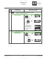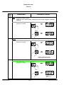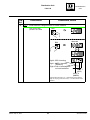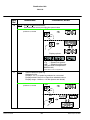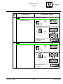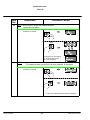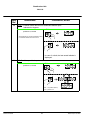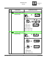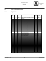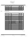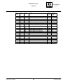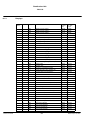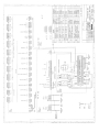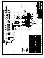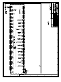
1
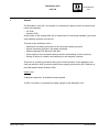
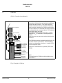
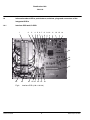
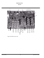
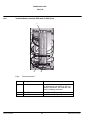
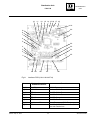
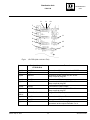
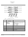
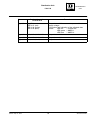
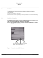
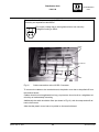
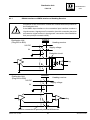
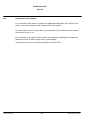
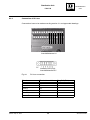
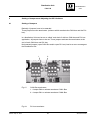
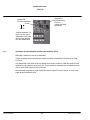
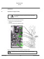
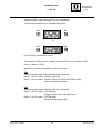
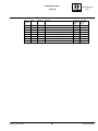
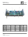
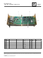
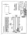
Raytheon Anschütz GmbH
Postfach 1166
D -- 24100 Kiel
Germany
Tel +49--4 31--30 19--0
Fax +49--4 31--30 19--501
Email [email protected]
www.raytheon--anschuetz.de
DISTRIBUTION UNIT
Type 138--118
1 Description
2 Installation
3647.DOC010302 Edition:
Sept. 17, 2008
Weitergabe sowie Vervielfältigung dieser Unterlage, Verwertung und
Mitteilung ihres Inhaltes nicht gestattet, soweit nicht ausdrücklich
zugestanden. Zuwiderhandlungen verpflichten zu Schadenersatz.
Copying of this document, and giving it to others and the use or
communication of the contents thereof, are forbidden without express
authority. Offenders are liable to the payment of damages.
Toute communication ou reproduction de ce document, toute
exploitation ou communication de son contenu sont interdites, sauf
autorisation expresse. Tout manquement à cette règle est illicite et
expose son auteur au versement de dommages et intérêts.
Sin nuestra expresa autorización, queda terminantemente prohibida la
reproducción total o parcial de este documento, así como su uso
indebido y/o su exhibición o comunicación a terceros. De los infractores
se exigirá el correspondiente resarcimiento de daños y perjuicios.
Distribution Unit
138--118
DISTRIBUTION
UNIT
CONTENTS
Page
Declaration of Conformity . . . . . . . . . . . . . . . . . . . . . . . . . . . . . . . . . . . . . . . . . . . . . . . .
1
1.1
General . . . . . . . . . . . . . . . . . . . . . . . . . . . . . . . . . . . . . . . . . . . . . . . . . . . . . . . . . . . . . . .
CAN--Bus . . . . . . . . . . . . . . . . . . . . . . . . . . . . . . . . . . . . . . . . . . . . . . . . . . . . . . . . . . . . .
1
2
1.2
Technical Data . . . . . . . . . . . . . . . . . . . . . . . . . . . . . . . . . . . . . . . . . . . . . . . . . . . . . . . . .
3
1.2.1
1.2.2
Mechanical Data . . . . . . . . . . . . . . . . . . . . . . . . . . . . . . . . . . . . . . . . . . . . . . . . . . . . . . .
Electrical Data . . . . . . . . . . . . . . . . . . . . . . . . . . . . . . . . . . . . . . . . . . . . . . . . . . . . . . . . .
3
3
1.3
Information about LED‘s, push buttons, switches, plugs and connectors
1.3.1
of the integrated PCB‘s . . . . . . . . . . . . . . . . . . . . . . . . . . . . . . . . . . . . . . . . . . . . . . . . .
Interface PCB and I/O PCB . . . . . . . . . . . . . . . . . . . . . . . . . . . . . . . . . . . . . . . . . . . . .
4
4
1.3.2
Terminal Board, Interface PCB and I/O PCB (E10) . . . . . . . . . . . . . . . . . . . . . . . . . .
10
2
2.1
Installation of the Distribution Unit . . . . . . . . . . . . . . . . . . . . . . . . . . . . . . . . . . . . . . . .
General remarks . . . . . . . . . . . . . . . . . . . . . . . . . . . . . . . . . . . . . . . . . . . . . . . . . . . . . . .
20
20
2.1.1
General information about establishing an earth connection . . . . . . . . . . . . . . . . .
23
2.2
2.2.1
Installation . . . . . . . . . . . . . . . . . . . . . . . . . . . . . . . . . . . . . . . . . . . . . . . . . . . . . . . . . . . .
Installation of the options . . . . . . . . . . . . . . . . . . . . . . . . . . . . . . . . . . . . . . . . . . . . . . . .
24
24
2.3
2.3.1
Connections . . . . . . . . . . . . . . . . . . . . . . . . . . . . . . . . . . . . . . . . . . . . . . . . . . . . . . . . . . .
Connection of the options . . . . . . . . . . . . . . . . . . . . . . . . . . . . . . . . . . . . . . . . . . . . . . .
26
28
2.3.2
RS422 -- Interface or NMEA Interface of Heading Receiver . . . . . . . . . . . . . . . . . .
27
2.3.3
3
Connection of DV--bus . . . . . . . . . . . . . . . . . . . . . . . . . . . . . . . . . . . . . . . . . . . . . . . . . .
Switching On the Distribution Unit . . . . . . . . . . . . . . . . . . . . . . . . . . . . . . . . . . . . . . . .
29
30
4
Setting of Jumpers and Adjusting the DIP--Switches . . . . . . . . . . . . . . . . . . . . . . . .
31
4.1
4.1.1
Setting of Jumpers . . . . . . . . . . . . . . . . . . . . . . . . . . . . . . . . . . . . . . . . . . . . . . . . . . . . .
Activation the termination resistors by switches (E10) . . . . . . . . . . . . . . . . . . . . . . .
31
32
4.2
Setting of DIP--Switches . . . . . . . . . . . . . . . . . . . . . . . . . . . . . . . . . . . . . . . . . . . . . . . .
34
4.2.1
4.2.2
Setting of DIP--Switches for DV--bus application . . . . . . . . . . . . . . . . . . . . . . . . . . . .
Setting of DIP--Switches for CAN--bus . . . . . . . . . . . . . . . . . . . . . . . . . . . . . . . . . . . .
34
35
4.2.3
General information in use of the DIP--Switch and push buttons . . . . . . . . . . . . . .
36
4.2.3.1
4.2.3.2
Setting of DV--bus address . . . . . . . . . . . . . . . . . . . . . . . . . . . . . . . . . . . . . . . . . . . . . .
Setting of CAN Bus address . . . . . . . . . . . . . . . . . . . . . . . . . . . . . . . . . . . . . . . . . . . . .
36
37
4.2.3.3
Adjustment of the 8 output channels (12 output channels --> E10) . . . . . . . . . . . .
39
4.2.3.4
4.2.3.5
Adjustment of NMEA Formats . . . . . . . . . . . . . . . . . . . . . . . . . . . . . . . . . . . . . . . . . . .
Adjustment of NMEA Formats (E10) . . . . . . . . . . . . . . . . . . . . . . . . . . . . . . . . . . . . . .
41
45
4.2.3.6
4.2.3.7
Left blank . . . . . . . . . . . . . . . . . . . . . . . . . . . . . . . . . . . . . . . . . . . . . . . . . . . . . . . . . . . . .
Scaling of RoT Output . . . . . . . . . . . . . . . . . . . . . . . . . . . . . . . . . . . . . . . . . . . . . . . . . .
49
50
4.2.3.8
Selection of magnetic compass . . . . . . . . . . . . . . . . . . . . . . . . . . . . . . . . . . . . . . . . . .
51
4.2.3.9
5
Displaying heading or speed information . . . . . . . . . . . . . . . . . . . . . . . . . . . . . . . . . .
Switching OFF the Distribution Unit . . . . . . . . . . . . . . . . . . . . . . . . . . . . . . . . . . . . . . .
52
53
6
Adjustments . . . . . . . . . . . . . . . . . . . . . . . . . . . . . . . . . . . . . . . . . . . . . . . . . . . . . . . . . . .
54
Edition: Nov. 28, 2005
I
3647.DOC010302
Distribution Unit
138--118
6.1
Adjustment of magnetic sonde . . . . . . . . . . . . . . . . . . . . . . . . . . . . . . . . . . . . . . . . . . .
54
7
Maintenance and Repair . . . . . . . . . . . . . . . . . . . . . . . . . . . . . . . . . . . . . . . . . . . . . . . .
56
7.1
8
Error indication . . . . . . . . . . . . . . . . . . . . . . . . . . . . . . . . . . . . . . . . . . . . . . . . . . . . . . . .
Functional description of DIP switch settings in the service mode . . . . . . . . . . . . .
56
58
8.1
Table of DIP--switch functions . . . . . . . . . . . . . . . . . . . . . . . . . . . . . . . . . . . . . . . . . . . .
81
8.1.1
8.1.2
Adjustments . . . . . . . . . . . . . . . . . . . . . . . . . . . . . . . . . . . . . . . . . . . . . . . . . . . . . . . . . . .
Adjustments E10 . . . . . . . . . . . . . . . . . . . . . . . . . . . . . . . . . . . . . . . . . . . . . . . . . . . . . . .
81
82
8.1.3
Displays . . . . . . . . . . . . . . . . . . . . . . . . . . . . . . . . . . . . . . . . . . . . . . . . . . . . . . . . . . . . . .
84
Spare parts catalogue
Drawings:
Distribution Unit Dimensional Drawing
138--118 HP005
Distribution Unit Wiring Diagram
Distribution Unit Wiring Diagram
138--118 HP008
138--118 HP013 (E10)
3647.DOC010302
II
Edition: Sept. 05, 2005
Distribution Unit
138--118
Edition: Sept. 05, 2005
III
DISTRIBUTION
UNIT
3647.DOC010302
Distribution Unit
138--118
3647.DOC010302
IV
Edition: Sept. 05, 2005
Distribution Unit
138--118
DISTRIBUTION
UNIT
Caused by technical progress the PC--Boards of the
Gyro Compass are changed.
Due to that some pictures and/or procedures have been
changed.
Respective changes are marked with “E10”.
Safety instructions
Caution:
z Installation, maintenance and repair work must be
carried out only by properly trained and qualified staff
with a good knowledge of national equipment safety
regulations.
Edition: Sept. 05, 2005
V
3647.DOC010302
Distribution Unit
138--118
Intentionally left blank
3647.DOC010302
VI
Edition: Sept. 05, 2005
Distribution Unit
138--118
1
DISTRIBUTION
UNIT
General
The Distribution Unit 138--118 consists of an aluminium casting in which 2 printed circuit
board are integrated.
-- I/O--PCB
-- Interface PCB.
At the bottom of the casting there are 40 cable inlets for connecting repeaters, gyros and
other heading receivers and sensors.
The task of this distribution Unit is:
-- Distribution of heading information to all connected heading receivers.
-- System monitoring by alarm--and status messages.
-- Gateway between DV--Bus and CAN--Bus.
-- Power supply of all connected heading receivers and heading sources (sensors).
-- Storing of values for variation and deviation for the magnetic compass.
There are no operating procedures during the normal operation of the distribution unit.
Only the setting to work--procedure needs some settings performed by DIP--Switches at
the CAN Network Modul Interface PCB.
Options are:
“Additional output box” for additional output signals.
“AC/DC--Converter” to generate the supply voltage for the distribution unit.
Edition: Sept. 05, 2005
1
3647.DOC010302
Distribution Unit
138--118
1.1
CAN-Bus
(CAN = Controller Area Network)
CAN bus
The CAN bus is a Multi-Master-Bus allowing the
connection of all devices and systems regardless
of their task and function. This means that any
number of devices can be connected. These devices must be designed for CAN bus technology.
For the CAN bus it is essential that every bus user
is addressable via a unique address. This address
is set within each bus user.
The usable address range is from 01(16) to 3F(16)
(address 00(16) is reserved for development purposes).
Each bus user can send and receive data via the
CAN bus.
Gyro compass
Gyro compass
GPS compass
Distribution unit
259.8
Operator unit
8 x heading
(course bus
or NMEA)
(12x E10)
The CAN bus must be terminated at both ends via
an ohmic resistor (125 Ohms). This terminating
resistor is activated by a jumper or a switch (E10)
on the respective PCB.
There are 2 redundant bus systems (CAN1 and
CAN2).
3 x step
1 x printer
1 x rate of turn
DV--bus
Magnetic
compass
Note:
The total length of CAN bus cable should not exceed 300m.
Fig.1:Principle of CAN bus
3647.DOC010302
2
Edition: Feb. 12, 2008
Distribution Unit
138--118
1.2
Technical Data
1.2.1
Mechanical Data
DISTRIBUTION
UNIT
see Dimensional Drawing “Distribution Unit 138--118.HP005”
Equipment category:
1.2.2
IP22
Electrical Data
Supply Voltage:
18VDC.......40VDC
Max. Current:
15A
(2 Gyros and 8 Repeaters)
Input:
--Spd--Log
--NMEA GPS
⎮ Pulslog
⎮ NMEA log
--Log
--CAN Bus
--DV Bus
--TMC
Output:
-- 8 Outputs (adjustable, with supply voltage 24V DC)
E10
-- 8 Outputs (adjustable, with supply voltage 24V DC)
-- 4 Outputs (adjustable, without supply voltage)
Heading serial (Course bus)
NMEA1
NMEA2
--RoT+/--10V (polarity adjustable)
--Course Printer Interface RS232C
--3 STEP--signal 1/6°/step (with supply voltage 35V DC)
-- DV--bus
-- CAN bus
Optional with an “Additional Output Box 146--103
Fast NMEA, SIF, STEP
Edition: Feb. 17, 2006
3
3647.DOC010302
Distribution Unit
138--118
1.3
Information about LED‘s, push buttons, switches, plugs and connectors of the
integrated PCB‘s
1.3.1
Interface PCB and I/O PCB
1
2
3
4 5 6 7 8
9 10 11
12 13 14
24
15
16
17
26
Fig.2:
3647.DOC010302
25
23
22 21 20 19 18
Interface PCB (138--118.100)
4
Edition: Sept. 05, 2005
Distribution Unit
DISTRIBUTION
UNIT
138--118
No.
Designation at the Interface
PCB
Remark
Fig.2/1
Terminal Board L1 of the
Distribution Unit
Connection of supply voltages
for the distribution unit itself and
for connected gyros, operator
unit and heading receivers.
Fig.2/2
LED H1
+5VDC DC/DC--Converter for
CAN--Bus and Course Bus
Fig.2/3
Terminal Board L1 of the
Interface PCB
Supply Voltage (+24V DC) for
this PCB
Fig.2/4
LED H7
+5VDC Course Bus
Fig.2/5
LED H4
+5VDC DV--Bus
Fig.2/6
Push Button B21
Reset Processor (CAN bus)
Fig.2/7
DIP--Switch B20
Adjustments for the Distribution
Unit
Fig.2/8
Push Button B23
Mode--Selection for DIP--Switch
B20
Fig.2/9
Jumper B2
Course--Bus/NMEA (Test only)
Fig.2/10 Display
Edition: Sept. 05, 2005
Fig.2/11 Push Button B22
Set--function for DIP--Switch B20
Fig.2/12 DIP Switch B24
DV--Bus setting (not used)
Fig.2/13 Push Button B11
Reset Processor (DV--Bus)
Fig.2/14 LED H6
Programming
Fig.2/15 Jumper B1
Programming (never set, development only)
Fig.2/16 Jumper B4
Bus--Resistor DV--Bus
(to be set if distribution unit is an
end device)
Fig.2/17 Terminal Board L2
Connection of Signals
Fig.2/18 Plug B6
CAN1--Bus
Fig.2/19 Jumper B31
Bus--Resistor CAN1--Bus
Fig.2/20 Jumper B32
Bus--Resistor CAN2--Bus
Fig.2/21 Plug B7
CAN2--Bus
Fig.2/22 LED H3
+5VDC CAN2--Bus
Fig.2/23 LED H2
+5VDC CAN1--Bus
Fig.2/24 LED H8
Processor clock
Fig.2/25 Fuse E1
10A, T; 24V DC input “Gyro1”
Fig.2/26 Fuse E2
10A, T; 24V DC input “Gyro2”
5
3647.DOC010302
Distribution Unit
138--118
1
2
3
4
5 6 7 8
9
10
52 51
47
48
49
50
43
44
45
46
39
40
41
42
33
34 30
35 31
36
32
37
38
29
28
27
23
24
25
26
19
20
21
22
15
16
17
18
11
12
13
14
Fig.3:I/O PCB (138--118.101)
3647.DOC010302
6
Edition: Sept. 05, 2005
Distribution Unit
DISTRIBUTION
UNIT
138--118
No.
Edition: Sept. 05, 2005
Designation at the I/O PCB
Remark
Fig.3/1
Connector B1
Connection to the Interface PCB
Fig.3/2
LED H30
35V DC Voltage (Step)
Fig.3/3
Push Button B40
Processor Reset
Fig.3/4
LED +5V5
+5VDC for RoT--Conversion
Fig.3/5
LED +5V4
+5VDC galvanically separated
supply voltage
Fig.3/6
LED +5V6
+5VDC for RS232C Interface
(Printer)
Fig.3/7
LED --15V
RoT Supply voltage
Fig.3/8
LED +15V
RoT Supply Voltage
Fig.3/9
LED H1
Processor Clock
Fig.3/10 LED H50
Relays ON/OFF Step--Supply
Fig.3/11 Plug B26
Output Channel 4 with 3 LED‘s
blue = NMEA 2
green = NMEA 1
red = Course bus
Fig.3/12 Plug B25
Output Channel 3 with 3 LED‘s
blue = NMEA 2
green = NMEA 1
red = Course bus
Fig.3/13 Plug B24
Output Channel 2 with 3 LED‘s
blue = NMEA 2
green = NMEA 1
red = Course bus
Fig.3/14 Plug B23
Output Channel 1 with 3 LED‘s
blue = NMEA 2
green = NMEA 1
red = Course bus
Fig.3/15 Fuse E4, 1A T
Protection for Channel 4
Fig.3/16 Fuse E3, 1A T
Protection for Channel 3
Fig.3/17 Fuse E2, 1A T
Protection for Channel 2
Fig.3/18 Fuse E1, 1A T
Protection for Channel 1
Fig.3/19 Plug B30
Output Channel 8 with 3 LED‘s
blue = NMEA 2
green = NMEA 1
red = Course bus
Fig.3/20 Plug B29
Output Channel 7 with 3 LED‘s
blue = NMEA 2
green = NMEA 1
red = Course bus
7
3647.DOC010302
Distribution Unit
138--118
No.
3647.DOC010302
Designation at the I/O PCB
Remark
Fig.3/21 Plug B28
Output Channel 6 with 3 LED‘s
blue = NMEA 2
green = NMEA 1
red = Course bus
Fig.3/22 Plug B27
Output Channel 5 with 3 LED‘s
blue = NMEA 2
green = NMEA 1
red = Course bus
Fig.3/23 Fuse E8, 1A T
Protection for Channel 8
Fig.3/24 Fuse E7, 1A T
Protection for Channel 7
Fig.3/25 Fuse E6, 1A T
Protection for Channel 6
Fig.3/26 Fuse E5, 1A T
Protection for Channel 5
Fig.3/27 Plug B3
+24V DC supply voltage for
repeaters
Fig.3/28 Plug B5
RoT--Output +/--10VDC
Fig.3/29 Plug B6
Plug for connection Printer
(RS232C Interface)
Fig.3/30 Plug B7
Step--output 1
Fig.3/31 Plug B8
Step--output 2
Fig.3/32 Plug B9
Step--output 3
Fig.3/33 LED H49
Indication Step--Interface 1
Fig.3/34 LED H48
Indication Step--Interface 2
Fig.3/35 LED H47
Indication Step--Interface 3
Fig.3/36 Fuse E9, 0.25A T
Protection for Step--output 1
Fig.3/37 Fuse E10, 0.25A T
Protection for Step--output 2
Fig.3/38 Fuse E11, 0.25A T
Protection for Step--output 3
Fig.3/39 Plug B20 with LED H11
Status--Signal with indication
“GPS COMPASS SELECTED”
Fig.3/40 Plug B17 with LED H8
Status--Signal with indication
“SENSOR DIFF. ALARM”
Fig.3/41 Plug B14 with LED H5
Status--Signal with indication
“SENSORALARM G3/GPS”
Fig.3/42 Plug B11 with LED H2
Status--Signal with indication
“SYSTEMALARM”
Fig.3/43 Plug B21 with LED H12
Status--Signal with indication
“CAN DISTURBED”
Fig.3/44 Plug B18 with LED H9
Status--Signal with indication
“TMC SELECTED”
Fig.3/45 Plug B15 with LED H6
Status--Signal with indication
“SENSORALARM TMC”
8
Edition: Sept. 05, 2005
Distribution Unit
DISTRIBUTION
UNIT
138--118
No.
Edition: Sept. 05, 2005
Designation at the I/O PCB
Remark
Fig.3/46 Plug B12 with LED H3
Status--Signal with indication
“SENSORALARM G1”
Fig.3/47 Plug B22 with LED H13
General Alarm RESET
Fig.3/48 Plug B19 with LED H10
Status--Signal with indication
“GYRO SELECTED”
Fig.3/49 Plug B16 with LED H7
Status--Signal with indication
“MONITORALARM GYRO/TMC”
Fig.3/50 Plug B13 with LED H4
Status--Signal with indication
“SENSORALARM G2”
Fig.3/51 Plug B2
TMC Connector IN/OUT
Fig.3/52 Jumper B41
Test purpose
9
3647.DOC010302
Distribution Unit
138--118
1.3.2
Terminal Board, Interface PCB and I/O PCB (E10)
1
3
3647.DOC010302
2
Fig.4:
Terminal board L1
No.
Designation
Remark
Fig.4/1
Terminal board L1
Connection for the supply voltage for
the Distribution Unit itself, for the connected compasses, the Operator Unit
and the heading receivers.
Fig.4/2
Fuse E1
10 A, T; 24V DC--Input Gyro 1
Fig.4/3
Fuse E2
10 A, T; 24V DC--Input Gyro 2
10
Edition: Sept. 05, 2005
Distribution Unit
DISTRIBUTION
UNIT
138--118
10
11
12 13 14 15 16 17 18
19
9
20
8
7
21
6
5
22
4
23
3
24
2
25
1
30 29
Fig.5:
No.
Edition: Sept. 05, 2005
28
27
26
Interface PCB (138--118.100 E10)
Designation at the
Interface PCB E10
Remark
Fig.5/1
Plug B7
CAN2--Bus
Fig.5/2
Switch B32
Resistor CAN2--Bus
Fig.5/3
LED H2
+5V DC CAN1--Bus
Fig.5/4
LED H3
+5V DC CAN2--Bus
Fig.5/5
LED H7
+5V DC Course bus
Fig.5/6
LED H4
+5V DC DV--Bus
Fig.5/7
Push button B21
Reset Processor (CAN--Bus)
Fig.5/8
LED H1
+5V DC DC/DC--Converter for CAN-bus and Course bus
11
3647.DOC010302
Distribution Unit
138--118
No.
3647.DOC010302
Designation at the
Interface PCB E10
Remark
Fig.5/9
Terminal board L1 of the Supply voltage +24V DC for the
Interface PCB
Interface PCB
Fig.5/10
Switch B2
Course bus/NMEA (test purpose only)
Fig.5/11
DIP--Switch B20
Einstellungen für die Distribution Unit
Fig.5/12
Push button B23
Mode selection together with DIP-Switch B20
Fig.5/13
LED H8
Processor clock (CAN--Bus Processor)
Fig.5/14
Display
Fig.5/15
Plug B9
Connection to flash CAN bus Processor
Fig.5/16
Push button B22
Set--Function together with
DIP--Switch B20
Fig.5/17
Plug B10
Connection to flash DV--bus Processor
Fig.5/18
Push button B11
Reset Processor (DV--bus)
Fig.5/19
LED H5
Processor clock (DV--bus Processor)
Fig.5/20
DIP--Switch B24
DV--bus adjustments (not used)
Fig.5/21
Plug B3
Connection to the I/O PCB
Fig.5/22
Switch B4
Bus resistor DV--bus
(only if the Distribution Unit is used as
an end device in a DV--bus application)
Fig.5/23
Plug B15
Connection for LOG, Control signals
and status signals
Fig.5/24
Plug B19
Connection MINS/RoT (Input)
Fig.5/25
Plug B17
Connection DV--Bus (Output)
Fig.5/26
Plug B18
Connection Kursbus (Output)
Fig.5/27
Plug B12
Connection GPS (Input)
Fig.5/28
Plug B13
Connection Data for SEC (Input)
Fig.5/29
Plug B6
Connection CAN1--bus
Fig.5/30
Switch B31
Resistor CAN1--bus
12
Edition: Sept. 05, 2005
Distribution Unit
DISTRIBUTION
UNIT
138--118
6 7 8 9 10 11
see Fig.7
12
13
14
5
4
15
3
2
Fig.6:
No.
1
see Fig.8
see Fig.9
see Fig.10
I/O PCB (138--118.101. E10)
Designation at the
I/O PCB E10
Remark
Fig.6/1
Switch B41
Test purpose only. Has to be always in closed
position.
Fig.6/2
Plug B2
TMC Connection IN/OUT
Fig.6/3
Plug B1
Connection to the Interface PCB
Fig.6/4
LED H38
35V DC for Step--function, lights up if present
Fig.6/5
Plug B10
Supply voltage 24V DC for the I/O PCB
Fig.6/6
Plug B4
Connection to flash
Fig.6/7,8,
9,10,11
LEDs
H42,H40,H41,H44,H43
Lights up if operating voltages + 5V DC and
+/-- 15V DC are present.
Fig.6/12
Push button B40
Reset CPU, after flashing
Fig.6/13
LED H1
Processor clock, blinks green
Fig.6/14
Switch B36
Not used, for future purpose
Fig.6/15
LED H50
Lights up red if the 35V DC for the Step--function
are switched off.
Edition: Sept. 05, 2005
13
3647.DOC010302
Distribution Unit
138--118
2
1
3
4
5
B 39
6
Fig.7:
No.
3647.DOC010302
I/O PCB (138--118.101. E10)
Designation at the
I/O PCB E10
Remark
Fig.7/1
LED H60
not used
Fig.7/2
Switch B42
not used
Fig.7/3
Push button B38
no function, not used
Fig.7/4
Switch B39
no function, not used
Fig.7/5
Push button B37
no function, not used
14
Edition: Nov. 28, 2005
Distribution Unit
DISTRIBUTION
UNIT
138--118
3
4
5
6
7
2
1
12
Fig.8:
No.
Edition: Sept. 05, 2005
11
10
9
8
I/O PCB (138--118.101. E10)
Designation at the
I/O PCB E10
Remark
Fig.8/1
Plug B16 with LED H7
Status--signal--connection with indication “MONITORALARM GYRO/TMC”
Fig.8/2
Plug B19 with LED H10
Status--signal--connection with indication “GYRO SELECTED”
Fig.8/3
Plug B22 with LED H13
General Alarm RESET
Fig.8/4
Plug B18 With LED H9
Status--signal--connection with indication “TMC SELECTED”
Fig.8/5
Plug B21 with LED H12
Status--signal--connection with indication “CAN DISTURBED”
Fig.8/6
Plug B17 with LED H8
Status--signal--connection with indication “SENSOR DIFF. ALARM”
Fig.8/7
Plug B20 with LED H11
Status--signal--connection with indication “GPS COMPASS SELECTED”
Fig.8/8
Plug B11 with LED H2
Status--signal--connection with indication “SYSTEMALARM”
15
3647.DOC010302
Distribution Unit
138--118
No.
3647.DOC010302
Designation at the
I/O PCB E10
Remark
Fig.8/9
Plug B14 with LED H5
Status--signal--connection with indication “SENSORALARM G3/GPS”
Fig.8/10
Plug B12 with LED H3
Status--signal--connection with indication “SENSORALARM G1/GPS”
Fig.8/11
Plug B15 with LED H6
Status--signal--connection with indication “SENSORALARM TMC”
Fig.8/12
Plug B13 with LED H4
Status--signal--connection with indication “SENSORALARM G2/GPS”
16
Edition: Sept. 05, 2005
Distribution Unit
DISTRIBUTION
UNIT
138--118
8
9
10
7
6
5
4
11
3
2
12
1
13
Fig.9:
No.
I/O PCB (138--118.101. E10)
Designation at the
I/O PCB E10
Remark
Fig.9/1
Plug B35
Connection of Course bus to the I/O PCB.
Fig.9/2
Plug B9
Connection of Step--output.
Fig.9/3
Fuse E11
Protection (0,25A, slow) 35V DC of the
Step--output at plug B9.
Fig.9/4
Plug B8
Connection of Step--output.
Fig.9/5
Fuse E 10
Protection (0,25A, slow) 35V DC of the
Step--output at plug B8.
Fig.9/6
Plug B7
Connection of Step--output.
Fig.9/7
Fuse E9
Protection (0,25A, slow) 35V DC of the
Step--output at plug B7.
Fig.9/8,9
and 10
LED H47, 48 and 49
Image of the Step--outputs
Fig.9/11
Plug B6
Connection of Course Printer.
Fig.9/12
Plug B5
Connection of RoT (analog).
Fig.9/13
Plug B3
24V DC connection to supply the repeaters
connected at the output channels 1 to 8.
Edition: Sept. 05, 2005
17
3647.DOC010302
Distribution Unit
138--118
(Channel 8) 4
5 (Channel 4)
(Channel 7) 3
6 (Channel 3)
(Channel 6) 2
7 (Channel 2)
(Channel 5) 1
8 (Channel 1)
12
(Channel 9)
10
(Channel 11) 9
11
(Channel 10)
(Channel 12)
Fig.10:
No.
I/O PCB (138--118.101. E10)
Designation at the
I/O PCB E10
Remark
Fig.10/1
Plug B 27
Fuse E5
LED 26 (red)
LED 27 (green)
LED 28 (blue)
Fig.10/2
B 28, E 6, H 29, H 30, H 31 Output channel 6
Fig.10/3
B 29, E 7, H 32, H 33, H 34 Output channel 7
Fig.10/4
B 30, E 8, H 35, H 36, H 37 Output channel 8
Fig.10/5
B 26, E 4, H 23, H 24, H25
Output channel 4
Fig.10/6
B 25, E 3, H 20, H 21, H22
Output channel 3
Fig.10/7
B 24, E 2, H 17, H 18, H 19 Output channel 2
Fig.10/8
B 23, E 1, H 14, H 15, H 16 Output channel 1
3647.DOC010302
Output channel 5 to connect repeater with supply
voltage.
Connection, protection and indication of the
adjusted data format.
LED red = Course bus
LED green = NMEA 1
LED blue = NMEA 2
18
Edition: Sept. 05, 2005
Distribution Unit
DISTRIBUTION
UNIT
138--118
No.
Designation at the
I/O PCB E10
Remark
Fig.10/9
Plug B 34
LED H 57 (red)
LED H 56 (green)
LED H 55 (blue)
Output channel 12 to connect repeater without
supply voltage.
Connection and indication of the adjusted data
format.
LED red
= Course bus
LED green = NMEA 1
LED blue
= NMEA 2
Fig.10/10
B 33, H 54, H 55, H 56
Output channel 11
Fig.10/11
B 32, H 51, H 52, H 53
Output channel 10
Fig.10/12
B 31, H 39, H 45, H 46
Output channel 9
Edition: Sept. 05, 2005
19
3647.DOC010302
Distribution Unit
138--118
2
Installation of the Distribution Unit
2.1
General remarks
Caution
When establishing cable connections ensure that the
cables are disconnected from the power supply.
It is essential to ensure that all cables are disconnected
from the power supply, if necessary measure the voltage
beforehand and/or disconnect the relevant distributor.
In order to ensure that the system operates correctly, it is essential that you follow the
procedures described below for establishing cable connections.
-- Strip approx. 180mm of the cable.
Make sure you do not damage the shielding layer.
-- Strip off the shielding to a remainder of approximately 15mm.
approx.
15mm
approx. 180mm
Fig.11
How to strip the connection cable
-- Screw the cable gland out from the distribution box and push the screw
connection components over the cable.
It is absolutely essential that the sequence (as shown in Fig.12) is adhered to.
-- Check the cone and counterpart on the earthing insert for corrosion and
if necessary remove corrosion using an appropriate process (emery board).
3647.DOC010302
20
Edition: Sept. 05, 2005
Distribution Unit
DISTRIBUTION
UNIT
138--118
-- Push the counterpart of the earthing insert as far as the end of the cable
shield.
-- Push the earthing insert cone below the shielding against the counterpart.
Observe a shared evenly distribution of the shielding via the cone (see Fig.12).
Wall and DIN socket
Earthing insert
-- Cone
-- Counterpart
Seal
+ Strain relief
Shielding
Washer
Counter nut
Fig.12
Making the cable entry
-- Insert the earthing insert, the seal with and the washer into the cable gland, place
the counter nut on top and hand-tighten.
-- Strip the cable cores to a length of approx. 1.5cm, twist slightly and clamp on the
cable end sleeves. Connect the cable strands in the junction box as shown in the
table below. Hand-tighten the terminal screws concerned
-- Check the connection is firm by pulling lightly.
Edition: Sept. 05, 2005
21
3647.DOC010302
Distribution Unit
138--118
Option: Cable connection with a screen clamp
Attach the angle with cross slotted screws
below the respective cable inlet at the housing. (angle and screws are part of the installation kit).
Strip off the cable according to section 2.1.
The screen must be led for appr. 15mm
through the cable inlet (as shown).
Jam the cable (screen area) with the screw-clamp at the angle and fix it with the knurled
head screw.
3647.DOC010302
22
Edition: Sept. 05, 2005
Distribution Unit
138--118
2.1.1
DISTRIBUTION
UNIT
General information about establishing an earth connection
In order to comply with the stringent EMC requirements, please abide by the information
given below regarding cable connections.
Use the cable types specified.
Earth connections should be connected to the gyro compass and to the junction box.
It is essential to ensure that these connections have a
common reference to the ship’s earth.
Any additional components (options) must also be connected to the common earth!
Fig.13:
Establishing an earth connection
All earth connections must be made as shown in Fig.13.
The earthing cable attached to the cable bracket must possess a cross-section of minimum 1.5 mm2.
The cable bracket should be mounted between two toothed discs.
Earth connections must be free of corrosion and well fastened.
Edition: Sept. 05, 2005
23
3647.DOC010302
Distribution Unit
138--118
2.2
Installation
The distribution unit has to be mounted according to the dimensional drawing
138--118.HP005.
The front cover should be removable.
Please note the comment depending the internal protection at the dimensional drawing.
2.2.1
Installation of the options
For installations of the options, as there are “Additional Output Box” and “AC/DC--Converter”, see service manual of the Compass STD 22 Compact.
NOTE: While connecting the AC/DC--Converter one cable inlet between “AC IN” and
“DC OUT” must not be used
AC In
DC Out
One cable inlet must not be used between “DC out” and “AC In” !!!
Fig.14:
3647.DOC010302
Connection at the AC/DC--Converter
24
Edition: Sept. 05, 2005
Distribution Unit
DISTRIBUTION
UNIT
138--118
The installation of the power supply (AC/DC--Converter) should only be performed by an experienced electrician.
The supply voltage has to be engineered as a low--security-voltage according to SELV.
Plastic
cover
Adhesive cable tie
mounts
Tie wrap
Fig.15
Cable connections at the AC/DC--Converter
To connect the cables to the terminal board, the plastic cover has to be pulled off from
the terminal board.
Cables should not be lengthened too long, to prevent a short circuit to a neighbour terminal by an inadvertently loosening.
Additionally the cable should be fixed (as shown in Fig.15) with tie wraps and self adhesive tie mounts.
After that the plastic cover has to be pulled on the terminal board.
Edition: Sept. 05, 2005
25
3647.DOC010302
Distribution Unit
138--118
2.3
Connections
At a Distribution Unit with DV--bus application no connections for speed and/or position should be made.
CAN--bus
Example:
Distribution Unit
DV--bus
NMEA Position/Speed
Log Direction/Speed
For example
Nautoconning
All connections to terminal boards and plugs have to be made according appended
drawings.
Please note manufacturer recommendations depending on the cable--diameters.
3647.DOC010302
26
Edition: Sept. 05, 2005
Distribution Unit
DISTRIBUTION
UNIT
138--118
2.3.1
RS422--Interface or NMEA Interface of Heading Receiver
Conclusion for the connection of NON RAYTHEON Anschütz products to
the Distribution Unit:
If the NMEA input interface or the coursebus input interface contains a
“signal common / signal ground” connection, then this connection has to be
connected to “signal common / signal ground” connection of the Distribition
Unit (see principle scematic below).
Distribution Unit
(Plug B23 to B30)
24V DC
0V
NMEA
Heading receiver
1
Supply voltage
2
3
Protection circuit
4
Heading
5
6
Distribution Unit
(Plug B23 to B30)
24V DC
0V
RS422
Heading receiver
1
Supply voltage
2
3
4
Heading
5
6
Must be connected to prevent potential differences.
Edition: Feb. 12, 2008
27
3647.DOC010302
Distribution Unit
138--118
2.3.2
Connection of the Options
For connection of the options, as there are “Additional Output Box” and “AC/DC--Converter”, see service manual of the Compass STD 22 Compact.
For connection of a UTC--signal (time--synchronisation of a connected course--printer),
see section 8 seq. no. 41.
For connection of an Alarm--Reset--function see respective drawings at the appendix.
With this function an alarm signal can be reset centrally.
This function has to be connected at plug B22 of the I/O PCB.
3647.DOC010302
28
Edition: Sept. 05, 2005
Distribution Unit
DISTRIBUTION
UNIT
138--118
2.3.3
Connection of DV--bus
Connections have to be made according section 2.1 and appended drawings.
Interface PCB:
Anschlußklemme L2
Interface PCB (E10):
Anschlußklemme B17
Fig.16:
Edition: Sept. 05, 2005
DV--bus connection
Function
Terminal board L2
Plug B17 (E10)
Screen A
22
1
Core A
23
2
Core A
24
3
Core B
25
4
Core B
26
5
Screen B
27
6
29
3647.DOC010302
Distribution Unit
138--118
3
Switching On the Distribution Unit
After connecting the supply voltage, the Distribution Unit is switched on.
All direct connected devices (as there are compass, and repeater with supply voltage) to
the Distribution Unit are supplied with operating voltage as well.
There is no separate switch for the Distribution Unit.
3647.DOC010302
30
Edition: Sept. 05, 2005
Distribution Unit
138--118
4
Setting of Jumpers and Adjusting the DIP--Switches
4.1
Setting of Jumpers
DISTRIBUTION
UNIT
Basically 3 jumpers have to be awarded.
These jumpers are the terminators (resistors which terminate the CAN--bus and the DV-bus).
Is a distribution Unit used as an so called “end--device” within a CAN--bus and DV--bus
application, all jumpers have to be set. These jumpers activates the terminators at the
end of each CAN--bus and DV--bus
Not inserted jumpers (open CAN--Bus and/or open DV--bus) lead to an error message at
the Distribution Unit.
1
Fig.17:
2
CAN--Bus terminators
1 = Jumper B32 to activate terminator CAN1--Bus
2 = Jumper B31 to activate terminator CAN2--Bus
Fig.18:
Edition: Sept. 05, 2005
DV--bus terminator
31
3647.DOC010302
Distribution Unit
138--118
Jumper B1
Programming
DV--bus
(never set while
operation)
Jumper B4
DV--bus terminator
1
2
Jumper between 1--2
has to be set, if the
distribution unit is an
end--device within a
DV--bus application
4.1.1
Activation the termination resistors by switches (E10)
Basically 3 switches have to be awarded.
These switches are the terminators (resistors which terminate the CAN--bus and the
DV--bus).
Is a distribution Unit used as an so called “end--device” within a CAN--bus and DV--bus
application, all switches have to be set. These switches activates the terminators at the
end of each CAN--bus and of the DV--bus
Not activated terminators (open CAN--Bus and/or open DV--bus) lead to an error message at the Distribution Unit.
3647.DOC010302
32
Edition: Sept. 05, 2005
Distribution Unit
DISTRIBUTION
UNIT
138--118
DV--bus
B4
CAN--bus
B32
Fig.19:
B31
Switches to activate the terminators
Switch B32 in position ON activates the terminator for CAN1--bus
Switch B31 in position ON activates the terminator for CAN2--bus
Switch B4 in position ON activates the terminator for DV--bus
Edition: Sept. 05, 2005
33
3647.DOC010302
Distribution Unit
138--118
4.2
Setting of DIP--Switches
4.2.1
Setting of DIP--Switches for DV--bus application
DIP--Switch B24
Fig.20:
DIP--Switch for DV--bus application
All DIP--Switches of B24 have to be switched to position “OFF”.
These switches are actually not used.
3647.DOC010302
34
Edition: Sept. 05, 2005
Distribution Unit
DISTRIBUTION
UNIT
138--118
4.2.2
Setting of DIP--Switches for CAN--bus
(B23)
2
(B22)
4
3
DIP--Switch 1
1
(B20)
DIP--Switch 8
Display
B22
B23
Fig.21:
8 7 6 5 4 3 2 1
DIP--Switch
E10
DIP--Switches, display and push buttons to select and adjust different
operation modes
1 = DIP--Switch B20 with 8 single switches
2 = Push button B23 to select the modes within the respective DIP--Switch settings
3 = Display
4 = Push button B22 to set selected mode
Edition: Sept. 05, 2005
35
3647.DOC010302
Distribution Unit
138--118
4.2.3
General information in use of the DIP--Switch and push buttons
The normal operation of the all DIP--Switches is the “DOWN”--position.
This means the respective switch is closed.
In the upper position the respective switch is open and by this, a mode can be selected
and adjusted.
After a switch is set into the upper position, a mode can be selected by the the push button on the left of the display (push button B23).
Before setting the selected mode the display--information does not blink.
After acknowledgement of selected mode with the push button on the right of the display
(push button B22) the display information is blinking -- this means selected mode is set.
After setting a mode all switches have to be set into the down--position (exception CAN-bus address).
4.2.3.1
Setting of DV--bus address
For DV--bus application in the meaning of information to distribution unit for DV--bus
operation and DV--bus address for the distribution unit see manual no.: 3648 “Operator
unit 130--613” under section “DV--bus application”.
3647.DOC010302
36
Edition: Sept. 05, 2005
Distribution Unit
DISTRIBUTION
UNIT
138--118
4.2.3.2
Setting of CAN Bus address
Each device within a CAN bus application has to be identified with an address.
This address must not be twice within this application (bus--conflict)!!
The CAN bus address is already adjusted by the manufacturer.
Below mentioned procedure to adjust the address is only necessary if a second Distribution Unit should be connected.
To read out the CAN bus address it is only necessary to switch the DIP switches 1 and 2
into the upper position (”OPEN”).
DIP--Switch B20
OPEN
B22
B23
Fig.22:
DIP--Switch position to adjust CAN--Bus address
Procedure:
-- Switches 1 and 2 of the DIP--Switch into the upper position. Display = Addr
-- Press push button B22 -- the actual address will be shown in the display.
-- With push button B23 the numbers will count up and with push button B22 the
numbers will count down. The numbers will be shown in the display.
Switches 1 and 2 into the lower position after the final number of the
CAN bus address is adjusted.
-- Operate push button B21 “RESET Processor” (Fig.2/6)
or
Switch off and on again the supply voltage to the Distribution Unit;
by this the address is set.
Edition: Sept. 05, 2005
37
3647.DOC010302
Distribution Unit
138--118
Operate push button B21 “RESET Processor” (Fig.2/6) to acknowledge
or
Switch OFF an ON again voltage supply to the Distribution
Unit, by this the changed address is set.
Below mentioned table shows the CAN bus addressees for one or several Distribution
Units.
Restrictions:
Address 00 must not be used!!
3647.DOC010302
Device(s)
CAN--Bus--Address
Operator Units
01 to 09
Sensors
(GPS--compass)
10 to 13
Sensors
(Gyro Compass)
14 to 19
Distribution Units
20 to 29
Repeaters
30 to ...
38
Edition: Sept. 05, 2005
Distribution Unit
DISTRIBUTION
UNIT
138--118
4.2.3.3
Adjustment of the 8 output channels (12 output channels --> E10)
Each of the 8 (12) output channels can be set to 3 different interfaces.
These interfaces are: Course bus, NMEA1 and NMEA2.
With the formats NMEA1 and NMEA2 to different configurations can be adjusted, these
configurations become active after selection (to the respective output channel).
For adjustment of this configurations see sections 4.2.3.4 .
DIP--Switch B20
OPEN
B23
Fig.23:
B22
DIP--Switch position to adjust the 8 (12) output channels
Procedure:
-- Switches 1, 2 and 3 of the DIP--Switch B20 into the upper position.
-- By each operation of push button B23 another channel and/or another format
referring to the selected channel is selected and displayed.
-- This adjustment has to be performed for each connected channel.
-- Each adjustment of a format has to be set by operating push button B22 (right side of
the display). Set format blinks on the display.
-- After adjustment of all connected channels, the DIP switches 1, 2 and 3 must be
switched into the “DOWN” position again.
Edition: Sept. 05, 2005
39
3647.DOC010302
Distribution Unit
138--118
Number of operations of
the push button B23
Display
after switching of switches 1, 2 and 3
(B20) into the upper position
Chn1
1x
2x
3x
HSEr
nME1
nME2
4x
Chn2
5x
6x
7x
HSEr
nME1
nME2
8x
Chn3
9x
10x
11x
HSEr
nME1
nME2
12x
Chn4
13x
14x
15x
HSEr
nME1
nME2
16x
Chn5
17x
18x
19x
HSEr
nME1
nME2
20x
Chn6
21x
22x
23x
HSEr
nME1
nME2
24x
Chn7
25x
26x
27x
HSEr
nME1
nME2
28x
Chn8
29x
30x
31x
HSEr
nME1
nME2
32x
Chn9
33x
34x
35x
HSEr
nME1
nME2
36x
Ch10
37x
38x
39x
HSEr
nME1
nME2
40x
Ch11
41x
42x
43x
HSEr
nME1
nME2
44x
Ch12
45x
46x
47x
HSEr
nME1
nME2
48x
Chn1
3647.DOC010302
Interface format
Plug at the PCB
Plug B23
Course bus (red LED)
NMEA1 (green LED)
NMEA2 (blue LED)
Plug B24
Course bus (red LED)
NMEA1 (green LED)
NMEA2 (blue LED)
Plug B25
Course bus (red LED)
NMEA1 (green LED)
NMEA2 (blue LED)
Plug B26
Course bus (red LED)
NMEA1 (green LED)
NMEA2 (blue LED)
Plug B27
Course bus (red LED)
NMEA1 (green LED)
NMEA2 (blue LED)
Plug B28
Course bus (red LED)
NMEA1 (green LED)
NMEA2 (blue LED)
Plug B29
Course bus (red LED)
NMEA1 (green LED)
NMEA2 (blue LED)
Plug B30
Course bus (red LED)
NMEA1 (green LED)
NMEA2 (blue LED)
Plug B31
Course bus (red LED)
NMEA1 (green LED)
NMEA2 (blue LED)
E10
E10
E10
E10
Plug B32
Course bus (red LED)
NMEA1 (green LED)
NMEA2 (blue LED)
E10
E10
E10
E10
Plug B33
Course bus (red LED)
NMEA1 (green LED)
NMEA2 (blue LED)
E10
E10
E10
E10
Plug B34
Course bus (red LED)
NMEA1 (green LED)
NMEA2 (blue LED)
E10
E10
E10
E10
Plug B23
40
Edition: Sept. 05, 2005
Distribution Unit
DISTRIBUTION
UNIT
138--118
4.2.3.4
Adjustments of NMEA Formats
The Distribution Unit can provide for each output one of three
different data formats (Course bus, NMEA1 and NMEA2).
Selected format can be recognized by the respective
LED colour.
The content of the course bus format cannot be changed, but
both NMEA formats can be adjusted concerning to telegram-type and repetition rate.
Procedure for NMEA1:
DIP--Switch B20
OPEN
B23
Fig.24:
B22
DIP--Switch position to adjust the NMEA1 interface
-- Switch 1 of the DIP--Switch into the upper position.
Operation of push
Display
button B23
after switching (B20)
switch 1 into the
nME1
upper position
1x
nME1.0
2x
nME0.1
3x
EHdT
4x
CHdT
5x
IHdG
6x
IroT
7x
EroT
*Adjustment of turn rate see section 4.2.3.7
Edition: Sept. 05, 2005
41
Interface
NMEA Channel1
NMEA 1.0sec
NMEA 0.1sec
HEHDT--Telegram
HCHDT--Telegram
HCHDG--Telegram
TIROT--Telegram*
HEROT--Telegram*
3647.DOC010302
Distribution Unit
138--118
Meaning of the telegram abbreviations:
HEHDT = Heading corrected, from a Gyro compass
HCHDT = Heading corrected, from a Magnetic compass
HCHDG = Heading uncorrected from a Magnetic compass
TIROT = Turn rate from a turn rate sensor
HEROT = Turn rate from a Gyro compass
-- By each operation of push button B23 another format is selected and displayed.
-- Each adjusted format has to be set wit push button B22 (right of the display).
The set format information blinks at the display.
-- After adjustment of all connected channels, the switch 1 has to be set
into lower position.
HCxxx--telegrams contain heading from magnetic compass. Not all heading--receivers are allowed to used this
heading source.
Telegramtype “HC” are transmitted from the respective
channel also, when a Gyro is selected at the connected
Operation Unit.
3647.DOC010302
42
Edition: Sept. 05, 2005
Distribution Unit
DISTRIBUTION
UNIT
138--118
Procedure for NMEA2:
DIP--Switch B20
OPEN
B23
Fig.25:
B22
DIP--Switch position to adjust the NMEA2 interface
-- Switch 2 of the DIP--Switch into the upper position.
Display
Operation of push
button B23
after switching (B20)
switch 2 into the
nME2
upper position
1x
nME1.0
2x
nM0.1
3x
EHdT
4x
CHdT
5x
IHdG
6x
IroT
7x
EroT
*Adjustment of turn rate see section 4.2.3.7
Interface
NMEA Channel2
NMEA 1.0sec
NMEA 0.1sec
HEHDT--Telegram
HCHDT--Telegram
HCHDG--Telegram
TIROT--Telegram*
HEROT--Telegram*
Meaning of the telegram abbreviations:
HEHDT = Heading corrected, from a Gyro compass
HCHDT = Heading corrected, from a Magnetic compass
HCHDG = Heading uncorrected from a Magnetic compass
TIROT = Turn rate from a turn rate sensor
HEROT = Turn rate from a Gyro compass
Edition: Sept. 05, 2005
43
3647.DOC010302
Distribution Unit
138--118
-- By each operation of push button B23 another format is selected and displayed.
-- Each adjusted format has to be set wit push button B22 (right of the display).
The set format information blinks at the display.
-- After adjustment of all connected channels, the switch 2 has to be set
into lower position.
Please note:
Restrictions for NMEA channel 1 and NMEA channel 2.
On selection of NMEA repetition rate of 1 second, all selected telegrams can be transmitted.
But on selection of NMEA repetition rate of 0.1 second, only 2 selected telegrams can
be transmitted.
More than 2 telegrams are not selectable at a repetition rate of 0.1 second.
HCxxx--telegrams contain heading from magnetic compass. Not all heading--receivers are allowed to used this
heading source.
Telegramtype “HC” are transmitted from the respective
channel also, when a Gyro is selected at the connected
Operation Unit.
3647.DOC010302
44
Edition: Sept. 05, 2005
Distribution Unit
DISTRIBUTION
UNIT
138--118
4.2.3.5
Adjustment of NMEA Formats (E10)
The Distribution Unit can provide for each output one of three
different data formats (Course bus, NMEA1 and NMEA2).
Selected format can be recognized by the respective
LED colour.
The content of the course bus format cannot be changed, but
both NMEA formats can be adjusted concerning to telegram-type and repetition rate.
Procedure for NMEA1:
DIP--Schalter B20
OPEN
B23
Fig.26:
B22
DIP--Switch position to adjust the NMEA1 interface
-- Switch 1 of the DIP--Switch into the upper position.
Number of operations of push button
B23
after switching switch 1
(B20) into the upper
position
1x
2x
3x
4x
5x
6x
7x
8x
9x
Display
Baudrate
nME1
Interface
NMEA Channel 1
CY. 1
CY.10
cY.10
CY.50
EHdT
CHdT
IHdG
IroT
EroT
4800Bd
4800Bd
9600Bd
38,4kBd
NMEA 1.0sec
NMEA 0.1sec
NMEA 0.1sec
NMEA 0.02sec
HEHDT--Telegram
HCHDT--Telegram
HCHDG--Telegram
TIROT--Telegram*
HEROT--Telegram*
* to adjust the turn rate, see section 4.2.3.7
Edition: Sept. 05, 2005
45
3647.DOC010302
Distribution Unit
138--118
Meaning of the telegram abbreviations:
CY and cY means “Cycle”
CY1
= 1Hz
CY10
= 10Hz
CY50 = 50Hz
HEHDT = Heading corrected, from a Gyro compass
HCHDT = Heading corrected, from a Magnetic compass
HCHDG = Heading uncorrected from a Magnetic compass
TIROT = Turn rate from a turn rate sensor
HEROT = Turn rate from a Gyro compass
-- By each operation of push button B23 another format is selected and displayed.
-- Each adjusted format has to be set wit push button B22 (right of the display).
The set format information blinks at the display.
-- After adjustment of all connected channels, the switch 1 has to be set
into lower position.
HCxxx--telegrams contain heading from magnetic compass. Not all heading--receivers are allowed to used this
heading source.
Telegramtype “HC” are transmitted from the respective
channel also, when a Gyro is selected at the connected
Operation Unit.
3647.DOC010302
46
Edition: Sept. 05, 2005
Distribution Unit
DISTRIBUTION
UNIT
138--118
Procedure for NMEA2:
DIP--Switch B20
OPEN
B23
Fig.27:
B22
DIP--Switch position to adjust the NMEA2 interface
-- Switch 2 of the DIP--Switch into the upper position.
Number of operations of push button
B23
after switching switch 2
(B20) into the upper
position
1x
2x
3x
4x
5x
6x
7x
8x
9x
Display
Baudrate
nME1
Interface
NMEA Channel 2
CY. 1
CY.10
cY.10
CY.50
EHdT
CHdT
IHdG
IroT
EroT
4800Bd
4800Bd
9600Bd
38,4kBd
NMEA 1.0sec
NMEA 0.1sec
NMEA 0.1sec
NMEA 0.02sec
HEHDT--Telegram
HCHDT--Telegram
HCHDG--Telegram
TIROT--Telegram*
HEROT--Telegram*
* to adjust the turn rate, see section 4.2.3.7
Meaning of the telegram abbreviations:
CY and cY means “Cycle”
CY1
= 1Hz
CY10
CY50
= 10Hz
= 50Hz
HEHDT = Heading corrected, from a Gyro compass
HCHDT = Heading corrected, from a Magnetic compass
HCHDG = Heading uncorrected from a Magnetic compass
TIROT = Turn rate from a turn rate sensor
HEROT = Turn rate from a Gyro compass
Edition: Sept. 05, 2005
47
3647.DOC010302
Distribution Unit
138--118
-- By each operation of push button B23 another format is selected and displayed.
-- Each adjusted format has to be set wit push button B22 (right of the display).
The set format information blinks at the display.
-- After adjustment of all connected channels, the switch 1 has to be set
into lower position.
Please note:
Restrictions for NMEA channel 1 and NMEA channel 2.
On selection of NMEA repetition rate of 1 second, all selected telegrams can be transmitted.
But on selection of NMEA repetition rate of 0.1 second, only 2 selected telegrams can
be transmitted.
More than 2 telegrams are not selectable at a repetition rate of 0.1 second.
HCxxx--telegrams contain heading from magnetic compass. Not all heading--receivers are allowed to used this
heading source.
Telegramtype “HC” are transmitted from the respective
channel also, when a Gyro is selected at the connected
Operation Unit.
3647.DOC010302
48
Edition: Sept. 05, 2005
Distribution Unit
138--118
4.2.3.6
Edition: Nov. 28, 2005
DISTRIBUTION
UNIT
Left blank
49
3647.DOC010302
Distribution Unit
138--118
4.2.3.7
Scaling of RoT Output
For the RoT--output an adjustment of the turn rate has to be performed.
DIP--Switch B20
OPEN
B22
B23
Fig.28:
DIP--Switch position to adjust the turn rate
Procedure:
-- Switch 3 of the DIP--Switch into the upper position.
Operation of push button
B23
after switching (B20) switch 3
into the upper position
1x
2x
3x
4x
Display
--ro-r 30
r100
r300
Gy
Rate of Turn
30 degree/minute
100 degree/minute
300 degree/minute
analog heading
output*
*Selection of “Gy” means: there is no RoT--function, the output is used for an analogue heading signal.
-- By each operation of push button B23 another rate of turn range is selected and
displayed.
-- Each adjusted rate has to be set wit push button B22 (right of the display).
The set format information blinks at the display.
-- After adjustment, the switch 3 has to be set into lower position.
Restriction:
If “Gy” is selected for an analog heading output,
no turn rate can be adjusted.
To test this function (RoT with 20°/minute) see manual for the compass STD 22.
3647.DOC010302
50
Edition: Feb. 17, 2006
Distribution Unit
DISTRIBUTION
UNIT
138--118
4.2.3.8
Selection of magnetic compass
DIP--Switch B20
OPEN
B22
B23
Fig.29:
DIP--Switch position to adjust application with Magnetic compass
With this adjustment it is to determine if a magnetic compass is connected to this application.
-- Switch 4 of the DIP--Switch (B23) into the upper position.
-- The display shows MAGn.
If this display--information blinks, then it is selected and the distribution unit is
prepared to support a magnetic compass.
-- By operating the push button B22 (right side) the selection is aborted. The display
information does not blink.
-- After adjustment, the switch 4 has to be set into lower position.
If a magnetic compass is connected to the Distribution Unit and
the setting is already performed, then the Operation Unit recognized the magnetic compass automatically.
But, if an external sensor as the magnetic sensor is disconnected (de--installation), a POWER OFF/POWER ON procedure
has to be performed at the Operation Unit (as a RESET).
Edition: Sept. 05, 2005
51
3647.DOC010302
Distribution Unit
138--118
4.2.3.9
Displaying heading or speed information
This setting allows to check the heading information of selected sensor, the speed information of the Log or information about supply voltages.
DIP--Switch B20
OPEN
B22
B23
Fig.30:
DIP--Switch position to adjust output of heading and speed values
Procedure:
Operation of push
button B23
after switching
switch 8 (B20) into
the upper position
1x
2x
3x
4x
Display
Heading information
Sen1
xxx.x°*
xxx.x°*
xxx.x°*
xxx.x°*
+/--Kts
Sen2
Sen3
Sen4
PLoG
no information with DV--bus application
*
5x
P--11
6x
P--35
11VDC supply voltage
of the I/O PCB
35VDC operating voltage for the 1/6 Step
function of the I/O PCB
Designations of SEN1 to SEN4 depends on the respective CAN bus address.
The lowest address is SEN1
-- Switch 8 of the DIP--Switch into the upper position.
-- By operating the push button B22 (right side) the display shows the heading value
(the speed or supply voltage) of the selected sensor (see table above).
-- After this check, the switch 8 has to be set into lower position.
3647.DOC010302
52
Edition: Sept. 05, 2005
Distribution Unit
138--118
5
DISTRIBUTION
UNIT
Switching OFF the Distribution Unit
By switching OFF the supply voltage, the distribution unit is switched OFF.
All direct connected devices to the Distribution Unit, as there are compass and repeaters
with supplied voltage are switched off as well.
A separate switching off of the Distribution Unit is not possible.
Edition: Sept. 05, 2005
53
3647.DOC010302
Distribution Unit
138--118
6
Adjustments
6.1
Adjustment of magnetic sonde
This adjustment should be performed only be well trained
technicians.
Necessary tools and measuring instruments
-- Screw driver to adjust potentiometer
-- Voltmeter
-- Iron tool to influence the magnetic sonde
TP0
TP12
TP11
R155
E10
R113 = SCALE
Switch B41
B2
Fig.31: Testpoint at the I/O PCB to adjust the magnetic sonde
Switch B41 has to be closed always. Switch position to the left.
3647.DOC010302
54
Edition: Sept. 05, 2005
Distribution Unit
138--118
DISTRIBUTION
UNIT
Adjustment after installation of the magnetic sonde
(see Fig.31)
The Distribution Unit is in operation.
Magnetic sonde is installed and connected to the Distribution Unit.
--
Switch the switches 6,7 and 8 of the DIP switch B20 into the upper position “OPEN”).
-- Operate push button B22 until the display shows “MAGS”.
-- Operate push button B23 once; the actual heading of the magnetic sonde is
displayed.
-- Measure the voltage at plug B2, there should be a voltage of 1,8Veff (400Hz)
between pin 2.1 and 2.2 .
-- Connect voltmeter (DC--range) at TP 11 or TP 12 (+) and TP0 (GND) at the I/O PCB.
-- Turn the magnetic sonde (in the holder) until a value between 4.3V and 4.6V is
displayed at the voltmeter.
-- If the voltage is less than 4.3V or higher than 4.6V, than the requested voltage has to
be adjusted with potentiometer R155 to a value between 4.3V and 4.6V.
-- If this value cannot be adjusted by potentiometer R155 (display in the Distribution
Unit shows “Err”), the distance between magnetic compass and sonde has to be
reduced. After that the voltage adjustment must be repeated until the heading value is
displayed (not “Err”).
-- After the voltage adjustment, the magnetic sonde has do be adjusted in that way, that
the display in the Distribution Unit shows the same heading value than the magnetic
compass.
If the potentiometer R113 is adjusted inadvertently
-- Divert the compass card into position 45° by an iron tool.
-- Voltage measurement at TP11 (+) and TP0 (GND
and
Voltage measurement at TP12 (+) and TP0 (GND)
Both values must be the same.
-- If applicable adjust potentiometer R113, so that both values are the same.
Edition: Sept. 05, 2005
55
3647.DOC010302
Distribution Unit
138--118
7
Maintenance and Repair
The Distribution Unit is maintenance free.
A repair is constrained to the exchange of the PCB‘s:
I/O PCB
Identnumber 138--118.101
Interface PCB
138--118.101 E10
Identnumber 138--118.103
138--118.100 E10
Operation during a repair can only be performed when the
CAN--bus is terminated.
It is absolute necessary that the CAN--bus is terminated
correctly on both ends.
If there is no terminator by jumpers within the respective
devices, than each CAN--bus (CAN1 and CAN2) has to be
terminated by, in total 4 resistors (each 120Ohm) from
CAN--low to CAN--high
Faults within the connected compass are not indicated. The have to be researched at
the display of the respective compass.
7.1
Error indication
An error is displayed by a blinking “ERRO”.
Fig.32: Error display at the Distribution Unit
3647.DOC010302
56
Edition: Sept. 05, 2005
Distribution Unit
DISTRIBUTION
UNIT
138--118
Operate the push button B23 during an error is displayed.
Two different information can be displayed after that.
B22
B23
or
B22
B23
Fig.33: Display to determine an error
Error indication “PCB0” points to a faulty Interface PCB, an error indication “PCB1”
points to a faulty I/O PCB.
Measures to continue determination of the error source:
PCB0
Operate both push buttons B23 and B22 at the same time.
Display = “Er.01” means: Interface PCB faulty.
Display = “Er.02” means: Interface PCB or I/O PCB or both PCB‘s faulty.
CAN--bus dialogue disturbed.
PCB1
Operate both push buttons B23 and B22 at the same time.
Display = “Er.01” means: I/O PCB faulty.
Supply voltage for the step output faulty
Display = “Er.02” means: I/O PCB faulty.
Internal voltage supply faulty.
Edition: Sept. 05, 2005
57
3647.DOC010302
Distribution Unit
138--118
8
Functional description of DIP switch settings in the Service mode
All data stated below should be selected and read out for servicing purposes only.
In standard operation the following data has no significance.
The Service Mode is switched ON with DIP--Switches 6+,7 and 8 into the upper position.
DIP--Schalter B20
OPEN
B23
Seq.
No.
1
B22
Indications
Comments, Notes
UnCo = (Uncorrected Compass) = heading without speed error correction value.
DIP--Switch B20:
positions 6,7 and 8
B23
3647.DOC010302
58
Displays the uncorrected gyro
heading
Edition: Sept. 05, 2005
Distribution Unit
DISTRIBUTION
UNIT
138--118
Seq.
No.
2
Indications
Comments, Notes
Corr = Corrected course (course taking SEC into account)
DIP--Switch B20:
positions 6,7 and 8
B22
1x
B23
3
GYr1 = Displays corrected heading for Gyro compass 1
B22
DIP--Switch B20:
positions 6,7 and 8
2x
B23
If there is no
“Gyro 1”
connected.
Edition: Sept. 05, 2005
59
3647.DOC010302
Distribution Unit
138--118
Seq.
No.
4
Indications
Comments, Notes
Addr = Displays CAN--bus address for Gyro Compass 1
DIP--Switch B20:
positions 6,7 and 8
B22
3x
B23
If there is no
“Gyro 1”
connected.
5
GYr2 = Displays corrected heading for Gyro compass 2
B22
DIP--Switch B20:
positions 6,7 and 8
4x
B23
If there is no
“Gyro 2”
connected.
3647.DOC010302
60
Edition: Sept. 05, 2005
Distribution Unit
DISTRIBUTION
UNIT
138--118
Seq.
No.
6
Indications
Comments, Notes
Addr = Displays CAN--bus address for Gyro Compass 2
DIP--Switch B20:
positions 6,7 and 8
B22
5x
B23
If there is no
“Gyro 2”
connected.
7
GYr3 = Displays corrected heading for Gyro compass 3
B22
DIP--Switch B20:
positions 6,7 and 8
6x
B23
If there is no
“Gyro 3”
connected.
Edition: Sept. 05, 2005
61
3647.DOC010302
Distribution Unit
138--118
Seq.
No.
8
Indications
Comments, Notes
Addr = Displays CAN--bus address for Gyro Compass 3
B22
DIP--Switch B20:
positions 6,7 and 8
7x
B23
If there is no
“Gyro 3”
connected.
9
MAGS = Displays heading of magnetic compass
B22
DIP--Switch B20:
positions 6,7 and 8
8x
B23
No heading available
or heading of magnetic compass faulty
No magnetic compass
connected
3647.DOC010302
62
Edition: Sept. 05, 2005
Distribution Unit
DISTRIBUTION
UNIT
138--118
Seq.
No.
10
Indications
MAGC =
Comments, Notes
Displays corrected heading or magnetic compass
Deviation and variation included
B22
DIP--Switch B20:
positions 6,7 and 8
8x
B23
No heading available
or heading of magnetic compass faulty
No magnetic compass
connected
11
MISS = Displays Variation value
B22
DIP--Switch B20:
positions 6,7 and 8
9x
B23
Edition: Sept. 05, 2005
63
3647.DOC010302
Distribution Unit
138--118
Seq.
No.
12
Indications
Comments, Notes
dEvI = Displays deviation value
Value out of an internal table, respective to the actual magnetic compass
heading
DIP--Switch B20:
positions 6,7 and 8
B22
10x
B23
13
Mrot = Displays Rate of Turn of the magnetic compass
DIP--Switch B20:
positions 6,7 and 8
B22
11x
B23
Display : Degree per minute
Sign negative: Direction Port
14
V--M = Displays this speed, which is manually set at the Operator Unit
DIP--Switch B20:
positions 6,7 and 8
B22
12x
B23
Range:
--90.0....90.0
3647.DOC010302
64
Edition: Sept. 05, 2005
Distribution Unit
DISTRIBUTION
UNIT
138--118
Seq.
No.
15
Indications
Comments, Notes
SCi = Serial Interface, telegram traffic on serial interface
B22
DIP--Switch B20:
positions 6,7 and 8
13x
B23
Contents
alternate
Digit 2: GPS--Interface
Digit 1: NMEA--Interface
(Speed in)
Digit 0: Sum of all telegrams
on both interfaces
UART 1
(GPS)
UART 2
(NMEA)
Digit diversifies at UART 1/2 --> data transfer at the interface
Digit non varying (must not be zero) --> no data transfer at the
interface
Edition: Sept. 05, 2005
65
3647.DOC010302
Distribution Unit
138--118
Seq.
No.
16
Indications
Comments, Notes
SrC.S = Source of Speed Information
Data about the source providing the speed value
B22
DIP--Switch B20:
positions 6,7 and 8
14x
B23
Display options:
PULS = Puls log*
vTg
= Speed over ground
vhW = Speed through water
(vtG and vhW corresponds to
NMEA 0183)
*also shown in DV--bus application
17
PULS =
Speed value from puls log
Indicated in Kts
Displays --no-- if no pulse log selected or connected
Displays 0000 if there is no input from selected source
Display range -- 80Kts to + 80 Kts (astern and ahead)
DIP--Switch B20:
positions 6,7 and 8
B22
15x
B23
3647.DOC010302
66
or
Edition: Sept. 05, 2005
Distribution Unit
DISTRIBUTION
UNIT
138--118
Seq.
No.
18
Indications
Comments, Notes
vtG.S = Speed from GPS--telegram (speed over ground)
B22
DIP--Switch B20:
positions 6,7 and 8
16x
B23
No telegram, DV--bus application
or faulty data from GPS
(vTg--telegram)
19
vtG.h = Course value from GPS telegram
DIP--Switch B20:
positions 6,7 and 8
B22
17x
B23
No telegram, DV--bus application,
or faulty data from GPS
(vTg--telegram)
Edition: Sept. 05, 2005
67
3647.DOC010302
Distribution Unit
138--118
Seq.
No.
20
Indications
Comments, Notes
vhw = Speed value in knots from NMEA telegram
(speed through water)
B22
DIP--Switch B20:
positions 6,7 and 8
18x
B23
No telegram, DV--bus application, or faulty serial speed
data (vHw--telegram)
21
SPd.A =
Speed in knots (actual value) (or value from DV--bus)
The speed for which the source has been selected, is displayed.
B22
DIP--Switch B20:
positions 6,7 and 8
19x
B23
In case of a fault the last actual speed is displayed.
3647.DOC010302
68
Edition: Sept. 05, 2005
Distribution Unit
DISTRIBUTION
UNIT
138--118
Seq.
No.
22
Indications
Comments, Notes
PoS = Position -- latitude in degrees
DIP--Switch B20:
positions 6,7 and 8
B22
20x
Automatic latitude from GPS or
actual latitude from the DV bus
B23
No latitude data available
(GPS defective) or DV--bus
application
23
ASPd = Alarm Speed
B22
DIP--Switch B20:
positions 6,7 and 8
21x
B23
3 2
Digit 3 ”Speed OK”
Digit 2 “ Speed Alarm
Digit 1 “Auto Speed OK”
Digit 0 “ Auto Alarm”
Edition: Sept. 05, 2005
Display 1
Display 0
Display 1
Display 0
Display 1
Display 0
Display 1
Display 0
69
1 0
Speed OK
Speed not OK
Speed Alarm
No Speed Alarm
Auto Speed OK
Auto Speed not OK
Auto Speed OK
No Auto Speed Alarm
3647.DOC010302
Distribution Unit
138--118
Seq.
No.
24
Indications
Comments, Notes
PoSn = Latitude value derives from automatic latitude input.
Indicated in degrees
B22
DIP--Switch B20:
positions 6,7 and 8
22x
Actual latitude (or manual set latitude value)
or automatic latitude from the DV bus
B23
In case of a fault, the last actual latitude is
displayed.
25
APoS = Alarm position input
B22
DIP--Switch B20:
positions 6,7 and 8
23x
B23
0001 = no position (alarm)
1100 = position o.k.
3647.DOC010302
70
Edition: Sept. 05, 2005
Distribution Unit
DISTRIBUTION
UNIT
138--118
Seq.
No.
26
Indications
Comments, Notes
nAn1 = 1st table for NMEA--requests
DIP--Switch B20:
positions 6,7 and 8
B22
24x
B23
L = telegram type GLL
G = telegram type GGA
t = telegram type VTG
h = telegram type VHW
1st digit = number of L--types
2nd digit = number of G--types
3rd digit = number of t--types
4th digit = number of h--types
27
nAn2 = nd table for NMEA--requests
DIP--Switch B20:
positions 6,7 and 8
B22
25x
B23
1x
B23
2x
b = telegram type VBW
l = telegram type SLL
1st digit = number of b--types
2nd digit = number of I--types
Edition: Sept. 05, 2005
71
3647.DOC010302
Distribution Unit
138--118
Seq.
No.
28
Indications
Comments, Notes
nSGG = NMEA--telegram (strings of the GGA--telegram)
B22
DIP--Switch B20:
positions 6,7 and 8
26x
B23
Number of ASCII--characters
per telegram
0000 = no telegram
The number of operations depends on the
number of characters.
(1 display content = max. 4 ASCII--characters)
See sequ. no. 29
3647.DOC010302
72
Edition: Sept. 05, 2005
Distribution Unit
DISTRIBUTION
UNIT
138--118
Seq.
No.
29
Indications
Comments, Notes
nSGL = NMEA--telegram (String of the GLL--telegram)
B22
DIP--Switch B20:
positions 6,7 and 8
27x
B23
1x
B23
Example
Length of the telegram
= 44 ASCII--characters
2x
B23
3x
B23
4x
B23
5x
B23
6x
Edition: Sept. 05, 2005
73
3647.DOC010302
Distribution Unit
138--118
Seq.
No.
cont.
29
Indications
Comments, Notes
nSGL = NMEA--telegram (Strings of the GLL--telegram)
DIP--Switch B20:
positions 6,7 and 8
B22
27x
B23
7x
B23
8x
B23
9x
B23
10x
B23
11x
B23
12x
Checksum
3647.DOC010302
74
Edition: Sept. 05, 2005
Distribution Unit
DISTRIBUTION
UNIT
138--118
Seq.
No.
cont.
29
Indications
Comments, Notes
nSGL = NMEA--telegram (Strings of the GLL--telegram)
DIP--Switch B20:
positions 6,7 and 8
B22
27x
B23
13x
With the 1st operation of the contact switch B23, the number of
ASCII--characters is displayed.
If the display shows “0000”, no telegram--output took place.
With every further operation of contact switch, 4 consecutive
ASCII--characters are displayed.
30
nSLL = NMEA--telegram (Strings of the SLL--telegram)
B22
DIP--Switch B20:
positions 6,7 and 8
29x
B23
1x
The number of operations depends on the number of characters
(1 display content = max. 4
ASCII--characters)
Number of ASCII-characters per telegram
0000 = no telegram
See seq. no. 29
Edition: Sept. 05, 2005
75
3647.DOC010302
Distribution Unit
138--118
Seq.
No.
31
Indications
Comments, Notes
nShw = NMEA--telegram (Strings of the VHW--telegram)
DIP--Switch B20:
positions 6,7 and 8
B22
30x
B23
1x
Number of ASCII--characters
per telegram
0000 = no telegram
The number of operations depends on
the number of characters.
(1 display content =
max. 4 ASCII--characters)
See seq. no. 29
32
nStG = NMEA--telegram (Strings of the VTG--telegram)
B22
DIP--Switch B20:
positions 6,7 and 8
31x
B23
1x
Number of ASCII--characters
per telegram
0000 = no telegram
The number of operations depends on
the number of characters.
(1 display content =
max. 4 ASCII--characters)
See seq. no. 29
3647.DOC010302
76
Edition: Sept. 05, 2005
Distribution Unit
DISTRIBUTION
UNIT
138--118
Seq.
No.
33
Indications
Comments, Notes
nSbw = NMEA--telegram (String of the VBW--telegram)
B22
DIP--Switch B20:
positions 6,7 and 8
31x
B23
1x
Number of ASCII--characters
per telegram
0000 = no telegram
The number of operations depends on
the number of characters.
(1 display content =
max. 4 ASCII--characters)
See seq. no. 29
34
tIME = Time since activating speed error correction
(Reset with power--off)
DIP--Switch B20:
positions 6,7 and 8
B22
32x
B23
1x
B23
2x
hours
days
(max. 99
minutes Seconds
B23
3x
Edition: Sept. 05, 2005
77
3647.DOC010302
Distribution Unit
138--118
Seq.
No.
35
Indications
Comments, Notes
Development only!
SCI . = Serial Communication Interface
NMEA Log/ GPS input)
DIP--Switch B20:
positions 6,7 and 8
B22
33x
B23
1x
The content of the two digits is during a data transfer
unrecognisable. Just the digits 1(16) and 0(16) are visible for a short moment; (10(16) means line feed).
All other sequentially indicated values are for development purpose only.
36
SGAd = CAN--bus address of selected gyro sensor
B22
DIP--Switch B20:
positions 6,7 and 8
34x
B23
1x
3647.DOC010302
78
Edition: Sept. 05, 2005
Distribution Unit
DISTRIBUTION
UNIT
138--118
Seq.
No.
37
Indications
AAdd =
Comments, Notes
Alarm address of a defective Gyro compass
DIP--Switch B20:
positions 6,7 and 8
B22
35x
B23
1x
0000 → no faulty Gyro
otherwise the CAN address.
38
dUin = Software version of the CAN--bus processor of the Interface PCB
B22
DIP--Switch B20:
positions 6,7 and 8
36x
B23
1x
39
doUt = Software version of the I/O--PCB of the Distribution Unit
B22
DIP--Switch B20:
positions 6,7 and 8
37x
B23
1x
Edition: Sept. 05, 2005
79
3647.DOC010302
Distribution Unit
138--118
Seq.
No.
40
Indications
Comments, Notes
dubS =Software version of the DV--bus processor of the Interface PCB
B22
DIP--Switch B20:
positions 6,7 and 8
38x
B23
1x
41
UTC = Time of *ZDA--Telegram
B22
DIP--Switch B20:
positions 6,7 and 8
39x
B23
1x
Hours
2x
Minutes
Seconds
3x
Day
Month
4x
Year
With this signal the time for a connected course printer is synchronised.
This UTC--signal normally is received via a GPS receiver. The signal may be connected
at terminal board L2, terminal 15(RX+) and terminal 16 (RX--)
3647.DOC010302
80
Edition: Sept. 05, 2005
Distribution Unit
DISTRIBUTION
UNIT
138--118
8.1
Table of DIP--switch functions
8.1.1
Adjustments
DIP-switch
Step
Display
Function
Push button B23
(left)
Push button B22
(right)
1+2
1
20 (address)
CAN--bus address setting of Distribution Unit.
Perform processor reset with B21 after changing address
upwards
downwards
4
1
MAGn
Magnetic compass activation
2
MAGn
Bring display to flash to activate input
choose
set
1
nME1
NMEA channel 1 configuration
2
nME1.0
Select for NMEA, 1/sec
choose
set
3
nME0.1
Select for NMEA, 10/sec
choose
set
4
EHdT
Select for HEHDT telegram
choose
set
5
CHdT
Select for HCHDT telegram
choose
set
6
IHdG
Select for HCHDG telegram
choose
set
7
IroT
Select for TIROT telegram
choose
set
8
EroT
Select for HEROT telegram
choose
set
1
nME2
NMEA channel 2 configuration
2
nME1.0
Select for NMEA, 1/sec
choose
set
3
nME0.1
Select for NMEA, 10/sec
choose
set
4
EHdT
Select for HEHDT telegram
choose
set
5
CHdT
Select for HCHDT telegram
choose
set
6
IHdG
Select for HCHDG telegram
choose
set
7
IroT
Select for TIROT telegram
choose
set
8
EroT
Select for HEROT telegram
choose
set
1
Chn1
Output channels 1--8 data selection
choose
2
HSEr
Select for heading serial (LED red)
choose
set
3
nME1
Select for NMEA, 1/sec (LED green)
choose
set
4
nME2
Select for NMEA, 10/sec (LED blue)
choose
set
5
Chn2
6
HSEr
Select for heading serial (LED red)
choose
set
7
nME1
Select for NMEA, 1/sec (LED green)
choose
set
8
nME2
Select for NMEA, 10/sec (LED blue)
choose
set
9
Chn3
10
HSEr
Select for heading serial (LED red)
choose
set
11
nME1
Select for NMEA, 1/sec (LED green)
choose
set
12
nME2
Select for NMEA, 10/sec (LED blue)
choose
set
13......
CHn4....8
1
2
1+2+3
choose
choose
choose
Same procedure than for channels above
Edition: Sept. 05, 2005
81
3647.DOC010302
Distribution Unit
138--118
8.1.2
DIP-switch
Step
Display
Function
Push button B23
(left)
3
1
--ro--
RoT output scaling
choose
2
r30
Select for 30°/minute
choose
set
3
r100
Select for 100°/minute
choose
set
4
r300
Select for 300°/minute
choose
set
5
Gy
Select for analog heading output
choose
set
Push button B23
(left)
Push button B22
(right)
Adjustments E10
DIP-switch
Step
Display
Function
1+2
1
20 (address)
CAN--bus address setting of Distribution Unit. upwards
Perform processor reset with B21 after changing address
4
1
MAGn
Magnetic compass activation
2
MAGn
Bring display to flash to activate input
1
downwards
choose
set
nME1
NMEA channel 1 configuration
1
CY.1
Adjusting Baudrate: 1/sec, 4800Bd
choose
set
2
CY.10
Adjusting Baudrate: 10/sec, 4800Bd
choose
set
3
cY.10
Adjusting Baudrate: 10/sec, 9600Bd
choose
set
4
CY.50
Adjusting Baudrate: 50/sec, 38.4kBd
choose
set
5
EHdT
Select for HEHDT telegram
choose
set
6
CHdT
Select for HCHDT telegram
choose
set
7
IHdG
Select for HCHDG telegram
choose
set
8
IroT
Select for TIROT telegram
choose
set
9
EroT
Select for HEROT telegram
choose
set
2
3647.DOC010302
Push button B22
(right)
nME2
NMEA channel 2 configuration
1
CY.1
Adjusting Baudrate: 1/sec, 4800Bd
choose
set
2
CY.10
Adjusting Baudrate: 10/sec, 4800Bd
choose
set
3
cY.10
Adjusting Baudrate: 10/sec, 9600Bd
choose
set
4
CY.50
Adjusting Baudrate: 50/sec, 38.4kBd
choose
set
5
EHdT
Select for HEHDT telegram
choose
set
6
CHdT
Select for HCHDT telegram
choose
set
7
IHdG
Select for HCHDG telegram
choose
set
8
IroT
Select for TIROT telegram
choose
set
9
EroT
Select for HEROT telegram
choose
set
82
Edition: Sept. 05, 2005
Distribution Unit
DISTRIBUTION
UNIT
138--118
DIP-switch
Step
Display
Function
Push button B23
(left)
1+2+3
1
Chn1
Output channels 1--8 data selection
choose
2
HSEr
Select for heading serial (LED red)
choose
set
3
nME1
Select for NMEA, 1/sec (LED green)
choose
set
4
nME2
Select for NMEA, 10/sec (LED blue)
choose
set
5
Chn2
6
HSEr
Select for heading serial (LED red)
choose
set
7
nME1
Select for NMEA, 1/sec (LED green)
choose
set
8
nME2
Select for NMEA, 10/sec (LED blue)
choose
set
9
Chn3
10
HSEr
Select for heading serial (LED red)
choose
set
11
nME1
Select for NMEA, 1/sec (LED green)
choose
set
12
nME2
Select for NMEA, 10/sec (LED blue)
choose
set
13......
CHn4....12
Push button B22
(right)
choose
choose
choose
Same procedure than for channels above
3
Edition: Sept. 05, 2005
1
--ro--
RoT output scaling
choose
2
r30
Select for 30°/minute
choose
set
3
r100
Select for 100°/minute
choose
set
4
r300
Select for 300°/minute
choose
set
5
Gy
Select for analog heading output
choose
set
83
3647.DOC010302
Distribution Unit
138--118
8.1.3
Displays
DIP-Switch
Step
Display
Function
Push button B23
(left)
Push button B22
(right)
8
1
Sen1
Heading value of Sensor 1
choose
display
2
Sen2
Heading value of Sensor 2
choose
display
3
Sen3
Heading value of Sensor 3
choose
display
4
Sen4
Heading value of Sensor 4
choose
display
5
PLoG
Speed value from puls log
choose
display
6
P--11
11V supply voltage of I/O PCB
choose
display
7
P--35
35V supply voltage for I/O PCB for step
choose
display
UnCo
Uncorrected course without SEC
display
choose
1
Corr
Corrected course with SEC
display
choose
2
Gyr1
Uncorrected heading of gyro 1
display
choose
3
Addr
CAN--bus address of gyro 1
display
choose
4
Gyr2
Uncorrected heading of gyro 2
display
choose
5
Addr
CAN--bus address of gyro 2
display
choose
6
Gyr3
Uncorrected heading of gyro 3
display
choose
7
Addr
CAN--bus address of gyro 3
display
choose
8
NAGS
Uncorrected heading of magnetic compass
display
choose
9
NAGC
Corrected heading of magnetic compass
display
choose
10
NISS
Variation value
display
choose
11
dEul
Deviation value
display
choose
12
Nrot
Rate of turn of magnetic compass
display
choose
13
u_N
Manual speed input from operator unit
display
choose
14
Sci
Telegram traffic on serial interface
display
choose
15
SrC.S
Speed source information
display
choose
16
PULS
Speed value from puls log
display
choose
17
vtG.S
Speed value from GPS
display
choose
18
vtG.h
Course value from GPS
display
choose
19
uhu.
Speed value from NMEA telegram (vhw)
display
choose
20
SPD.A
Selected speed value in knots
display
v
21
PoS
Latitude in degrees
display
choose
22
ASPD
Alarm speed information
display
choose
23
PoSn
Latitude from automatic latitude input
display
choose
24
APoS
Alarm position input information
display
choose
25
nAn1
1st table of NMEA requests
display
choose
26
nAn2
2nd table of NMEA requests
display
choose
27
nSGG
String of GGA telegram
display
choose
28
nSGL
String of GLL telegram
display
choose
29
nSLL
String of SLL telegram
display
choose
30
nShu
String of VHW telegram
display
choose
31
nStG
String of VTG telegram
display
choose
32
nSbu
String of VBW telegram
display
choose
6+7+8
3647.DOC010302
84
Edition: Sept. 05, 2005
Distribution Unit
DISTRIBUTION
UNIT
138--118
DIP-Switch
Edition: Sept. 05, 2005
Step
Display
Function
Push button B23
(left)
Push button B22
(right)
33
tINE
Time since activating SEC
display
choose
34
SCI
Display serial communication interface
display
choose
35
SGAd
CAN--bus address of selected sensor
display
choose
36
AAdd
Alarm address of defective Gyro
display
choose
37
dUIn
Software version interface pcb processor
display
choose
38
doUt
Software version I/O pcb processor
display
choose
39
dubs
Software version DV--bus processor
display
choose
40
UtC
Time telegram content
display
choose
85
3647.DOC010302
Distribution Unit
138--118
Intentionally left blank
3647.DOC010302
86
Edition: Sept. 05, 2005
Distribution Unit
Type 138--118.NG001
ANSCHÜTZ
1
Ersatzteilkatalog
SPARE PARTS
CATALOGUE
2
5
3
4
Pos. Lager--Nr.
Stock--No.
Benennung
Designation
Zeichnungs.Nr.
Part--No.
Stck. Herst.--Code Versorgungs--Nr.
Qty. MFRC
NSN
1
3609431
Interface PCB, AT
Interface PCB, recond
138--118.103 AT
1
D2865
2
3609430
I/O PCB, AT
I/O PCB, recond
138--118.101 AT
1
D2865
3
1.762017
G--Sicherungseinsatz
Fuse
8
D3841
4
1760517
G--Sicherungseinsatz
Fuse
3
D3841
5
1762137
G--Sicherungseinsatz
Fuse
T 1 A L 250 V
IEC 127--2
T 0,25 A L 250 V
IEC 127--2
T 10A 250 V
7006565
2
D2598
5920--12--167--4252
5920--00--780--8905
All depicted items which are not mentioned in the text are not applicable for this unit. Since further development may necessit
ate making modifications to existing
equipment, its conformity with the relevant illustrations and drawings is not always ensured. Raytheon Marine will be under no liability whatever that may arise from any
such differences.
14.626
RA/S--SU 0505 EDITION 01
Distribution Unit
Type 138--118.NG001, NG001 E10
ANSCHÜTZ
1
Ersatzteilkatalog
SPARE PART S
CATALOGUE
2
5
3
4
Pos. Lager--Nr.
Stock--No.
1 3609701
Benennung
Designation
Interface PCB, AT
2
3609702
I/O PCB, AT
3
1.762017
G--Sicherungseinsatz
4
1760517
G--Sicherungseinsatz
5
1762137
G--Sicherungseinsatz
Zeichnungs--Nr.
Part--No.
Interface PCB, recond. 138--118.100 AT
E10.X01
I/O PCB, recond.
138--118.101 AT
E10.X01
Fuse
T 1 A L 250 V
IEC 127--2
Fuse
T 0,25 A L 250 V
IEC 127--2
Fuse
T 10 A 250 V
7006565
Stck. Herst.--Code Versorgungs--Nr.
Qty. MFRC
NSN
1
D2865
1
D2865
8
D3841
3
D3841
2
D2598
5920--12--167--4252
5920--00--780--8905
All depicted items w hich are not mentioned in the tex t are not applicable for this uni t. Since further dev elopment may necessit ate making modifications to ex isting
equipment, its conformity w ith the relev ant illustrations and draw ings is not alw ays ensured. Raytheon Anschütz w ill be under no liability whatever that may arise
from any such differences.
14.626
RA/ST--SU 0603 EDITION 02
1
22.06.07
22.06.07