1
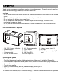
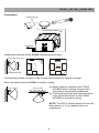
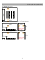
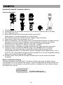
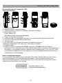
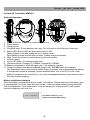
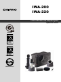
IWA-200 IWA-220 Infrared Wall Mounted Amplifier System Operation manual ISO 9001 R EG ISTER ED IS O 140 01 ISO 14001 R EG ISTER ED OHSAS 180 01 OHSAS 18001 GREEN PRODUCT Thank you for purchasing our infrared wireless microphone system. Please be sure to read the user's manual thoroughly and keep it for future reference. Cautions Do not cover the infrared emitter area of the wireless transmitter or the surface of the infrared sensor. Do not use the transmitter too close to speakers to prevent feedback. Do not replace the battery when power is on. Do not install near heat source or in a place subject to direct sunlight, excessive dust, mechanical vibration or shock. Do not use two transmitters on one channel at same time because it will cause abnormal operation. Parts and functions of amplifier 1 4 2 3 5 6 7 8 11 9 10 12 13 1. 2. 3. 4. 5. CH 1/CH 2 power indicators Infrared sensor Power switch Volume control MIC IN volume control 6. AUX IN volume control 7. TONE control 8. MIC input 9. LINE input R/L 10. LINE output R/L 11. External sensor input *3 12. DC input 13. External speaker output (4Ω load) Operating the system 1. First, find the optimal location with the widest view of the room to install the IR amplifier. 2. Connect power adaptor into nearby power outlet, and then connect the DC plug of adaptor to the amplifier. 3. Turn on the amplifier. 4. Switch on the transmitter and the channel indicator(s) will light up. 5. Adjust the volume control of amplifier to comfortable level. TIP: Reduce the treble slightly if feedback/howling, or operate transmitter further from speakers. -1- ISO 9001|ISO 14001|OHSAS 18001 Connections External sensor or IWA-200/220 amplifier AC adaptor Installing the external sensor IS-20A (wall/ceiling-mount type) fixing holder with a screw angle-adjustable shaft Find the best position for sensor to be mounted as illustrated for optimal coverage. Mount the external sensor IS-20A on a wall or ceiling. wall mounting ceiling mounting (a) Mount (Refer to illustration) the FIXING HOLDER (wall or ceiling) using a screw (provided) or two double-coated tapes (b) Find the best position with wide view of the room. Mount the sensor on the FIXING HOLDER on the wall or ceiling. NOTE: The LED of infrared sensor will turn red when power on. If not, please check your connections. -2- Installing the external sensor IS-30A (ceiling-mount type) In an ordinary space such as a classroom 1. Locate the IS-30A sensor in the middle of the ceiling, as illustrated below 2. Connect the sensor cable to the receiver. 3. Turn on the IR system and amplifier then operation can be started. In a larger space such as a fitness center 1. Locate 2 or 3 IS-30A sensors on the suggested positions on the cater-corner of the ceiling, as illustrated below. 2. Connect all sensor cables to the receiver. 3. Turn on the IR system and amplifier then operation can be started. Other sensor installing recommendations IS-30A rostrum IS-20A IRX2 One IS-20A wall sensor+one IS-30A ceiling sensor Ex: 10x10 sqm classroom IS-20A IRX2 rostrum IS-30A IS-30A 3~3.5m 1.5m please be careful of the angles -3- ISO 9001|ISO 14001|OHSAS 18001 Two IS-20A wall sensors rostrum IS-20A IRX2 IS-20A IS-20A IRX2 please be careful of the angles IS-20A rostrum IS-20A 2.5m 1.5m rostrum IRX2 Ex: 10x10 sqm classroom IS-20A 3~3.5m 1.5m please be careful of the angles -4- Handheld/Pendant IR Transmitter IWH-401 Parts and functions 1 2 3 4 5 7 8 6 9 1. 2. 3. 4. Cartridge screen. Infrared emitter. IR ray radiates from here. Do not block or hold this part of the body. Anti-rolling color ring. Status LED: Bicolor LED will glow when switch is put to ON. Green: Battery is full and transmitter is in normal mode. Red: Battery is weak and will shut off soon. Please charge the battery. 5. Power switch: Slide to turn transmitter on or off. 6. Battery compartment. Turn the battery cover counterclockwise and pull out. Make sure the transmitter is turned off when installing or replacing batteries. Install the new battery according to its correct polarity. IWH-401 uses only 1 AA battery to operate. 7. Channel selector. Channel A: 2.08MHz, Channel B: 2.54MHz 8. Sensitivity control. Clockwise to increase sensitivity level. Factory preset is max level. 9. Charging contact, workable with HC-40 (single-unit) / HC-402 (dual-unit) charger. Please note: This transmitter has a unique inbuilt safety feature to protect from overcharging the battery. It incorporates a special charging function enabled when 1cm of the PVC cover of the battery’s negative end is removed by 1cm. Any rechargeable batteries used must be used this way for safe charging. 10. Pendant holder. Place IWH-401 through this holder and it can be used as a pendant transmitter. Battery installation/charging Unscrew the battery cover and install 1 AA battery. Please make sure the battery type is rechargeable if it's to be used with the charger. It can be charged without being removed from the transmitter. If the transmitter is to be left unused for a long period of time, please remove the battery until next use. One Alkaline battery or 1cmnegative-peeled AA NiMH battery -5- ISO 9001|ISO 14001|OHSAS 18001 Handheld/Pendant IR Transmitter ITX2 Parts and functions 1 2 3 4 5 11 6 7 8 9 10 12 1. 2. 3. 4. Cartridge screen. Release buttons of pendant holder. Channel selector. Channel A: 2.08MHz, Channel B: 2.54MHz Bicolor status LED. Green: Battery full. Red: Battery weak and needs recharging. 5. Power on-off/audio mute switch. 6. Infrared emitter. IR ray radiates from here. Do not block or hold this part of the body. 7. Line input (Φ3.5mm) for external audio input. 8. Volume control. 9. Mic input (Φ2.5mm) for external headset or lavalier microphone. 10.Battery compartment. ITX2 uses only 1 AA battery to operate. 11.Pendant holder. 12.Charging contact, workable with HC-42 (single-unit) / HC-422 (dual-unit) charger.. Please note: This transmitter has a unique inbuilt safety feature to protect from overcharging the battery. It incorporates a special charging function enabled when 1cm of the PVC cover of the battery’s negative end is removed by 1cm. Any rechargeable batteries used must be used this way for safe charging. Battery installation/charging Press and slide off the battery cover and install 1 AA battery. Please make sure the battery type is rechargeable if it's to be used with the charger. It can be charged without being removed from the transmitter. If the transmitter is to be left unused for a long period of time, please remove the battery until next use. One Alkaline battery or 1cmnegative-peeled AA NiMH battery -6- Handheld IR Transmitter IWH-301 Parts and functions 1 2 3 6 5 7 4 8 1. Cartridge screen. 2. Status LED: Bicolor LED will glow when switch is put to ON: Green: Battery is full and transmitter is in normal mode. Red: Battery is weak and will shut off soon. Please charge the battery. 3. Power switch: Slide to turn transmitter on or off. 4. Infrared emitter. IR ray radiates from here. Do not block or hold this part of the body. 5. Battery compartment. Turn the battery cover counterclockwise and pull out. Make sure the transmitter is turned off when installing or replacing batteries. Install the new battery according to its correct polarity. IWH-301 uses only 2 AA batteries to operate. 6. Sensitivity control. Clockwise to increase sensitivity level. Factory preset is max level. 7. Channel selector. Channel A: 2.08MHz, Channel B: 2.54MHz 8. Charging contact, workable with HC-20+ charger.. Please note: This transmitter has a unique inbuilt safety feature to protect from overcharging the battery. It incorporates a special charging function enabled when 1cm of the PVC cover of the battery’s negative end is removed by 1cm. Any rechargeable batteries used must be used this way for safe charging. Battery installation/charging Unscrew the battery cover and install 2 AA batteries. Please make sure the battery type is rechargeable if it's to be used with the charger. It can be charged without being removed from the transmitter. If the transmitter is to be left unused for a long period of time, please remove the battery until next use. Two Alkaline batteries or 1cmnegative-peeled AA NiMH battery -7- ISO 9001|ISO 14001|OHSAS 18001 Pendant IR Transmitter IWM-402 Parts and functions 1 4 9 7 2 3 5 6 11 8 10 Mic in (Φ2.5mm). Headset or lavalier microphone. Power switch. Charging port. IR emitter area. IR ray radiates from here. Do not block or hold this part of the body. Status LED: Bicolor LED will glow when switch is ON. Green: Battery is full and transmitter is in normal mode. Red: Battery is weak and will shut off soon. Please charge the battery. 6. Mute. Press this button to mute/resume audio transmission. 7. Volume control. 8. Line in (Φ3.5mm), for external audio input. 9. Channel selector. Channel A: 2.08MHz, Channel B: 2.54MHz 10. Battery compartment. IWM-402 uses only 1 AA battery to operate. 11. Charging contact, workable with HC-40 (single-unit) / HC-402 (dual-unit) charger. This transmitter has a unique inbuilt safety feature to protect from overcharging the battery. It incorporates a special charging function enabled when 1cm of the PVC cover of the battery’s negative end is removed by 1cm. Any rechargeable batteries used must be used this way for safe charging. 1. 2. 3. 4. 5. Battery installation/charging Open the battery compartment and on install 1 AA battery. Please make sure the battery type is rechargeable if it's to be used with the charger. It can be charged without being removed from the transmitter. If the transmitter is to be left unused for a long period of time, please remove the battery until next use. One Alkaline battery or 1cmnegative-peeled AA NiMH battery -8- -9- ISO 9001|ISO 14001|OHSAS 18001 -10- CHIAYO ELECTRONICS CO.,LTD. Http://www.chiayo.com.tw|Email: [email protected] Office: 30, Lane 27, Section 4, Jen-Ai Road, Taipei 10685, Taiwan|Tel: 886-2-27415741|Fax: 886-2-27525242 Factory: 88, Chung-Hsiao Street 2, Chiayi 60080, Taiwan|Tel: 886-5-2711000|Fax: 886-5-5767611