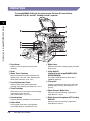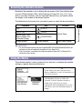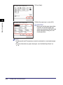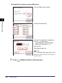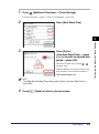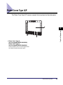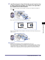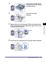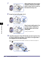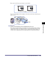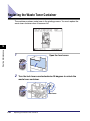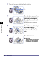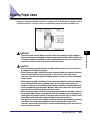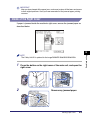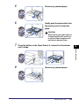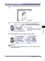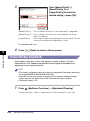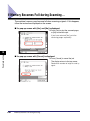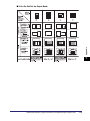
1
Reference Guide
Please read this guide before operating this product.
After you finish reading this guide, store it in a safe place for future reference.
ENG
imageRUNNER
2545i/2545
2535i/2535
2530i/2530
2525i/2525
2520i/2520
Reference Guide
Manuals for the Machine
The manuals for this machine are organized as shown below. Please refer to them for detailed
information. Some manuals may not be needed for certain system configurations and products
purchased.
Guides with this symbol are printed manuals.
• Quick Reference for Basic Operations
• Legal Notices
• Setup Instructions
• Basic Operations
• Troubleshooting
• Copying Instructions
• Sending and Fax Instructions
• Remote User Interface Instructions
• Network Connectivity
• Security Management
• Color Network ScanGear Instructions
• USB Memory Media Printing Instructions
• PS/PCL/UFRII LT Printer Instructions
• Windows Printer Driver Instructions
• Windows Fax Driver Instructions
• Macintosh Printer Driver Instructions
CD-ROM
Guides with this symbol are PDF manuals included on the
accompanying CD-ROM.
Easy Operation Guide
CD-ROM
User’s Guide
Reference Guide
(This Document)
CD-ROM
Copying Guide
CD-ROM
Sending and Facsimile Guide
CD-ROM
Remote UI Guide
CD-ROM
System Settings Guide
CD-ROM
Network ScanGear Guide
CD-ROM
Printer Guide
CD-ROM
Windows Printer Driver Guide
CD-ROM
Windows Fax Driver Guide
CD-ROM
Mac Printer Driver Guide
CD-ROM
To view the manual in PDF format, Adobe Reader/Adobe Acrobat Reader is required. If Adobe Reader/Adobe Acrobat Reader is not installed on your
system, please download it from the Adobe Systems Incorporated website.
How This Manual Is Organized
Chapter 1
Introduction to imageRUNNER 2545 Series
Chapter 2
Basic Operations
Chapter 3
Configuring the Machine’s Basic Settings
Chapter 4
Optional Equipment
Chapter 5
Routine Maintenance
Chapter 6
Troubleshooting
Chapter 7
Appendix
Includes tables detailing the Additional Functions settings, the available paper stock,
the relationship between original orientation and preprinted paper output, the
multifunctional operations, and the specifications of the main unit and optional
equipment, as well as the index.
Considerable effort has been made to ensure that this manual is free of inaccuracies and omissions. However, as we are constantly improving our
products, if you need an exact specification, please contact Canon.
Contents
Preface . . . . . . . . . . . . . . . . . . . . . . . . . . . . . . . . . . . . . . . . . . . . . . . . . . . . . . . . . ix
How to Use This Manual . . . . . . . . . . . . . . . . . . . . . . . . . . . . . . . . . . . . . . . . . . . ix
Symbols Used in This Manual . . . . . . . . . . . . . . . . . . . . . . . . . . . . . . . . . . . . . . ix
Keys Used in This Manual . . . . . . . . . . . . . . . . . . . . . . . . . . . . . . . . . . . . . . . . . ix
Illustrations Used in This Manual . . . . . . . . . . . . . . . . . . . . . . . . . . . . . . . . . . . . x
Displays Used in This Manual . . . . . . . . . . . . . . . . . . . . . . . . . . . . . . . . . . . . . . x
Abbreviations Used in This Manual . . . . . . . . . . . . . . . . . . . . . . . . . . . . . . . . . . xi
Trademarks . . . . . . . . . . . . . . . . . . . . . . . . . . . . . . . . . . . . . . . . . . . . . . . . . . . . xi
Operations and Terms Used in the Manuals . . . . . . . . . . . . . . . . . . . . . . . . . . . xi
Legal Notices . . . . . . . . . . . . . . . . . . . . . . . . . . . . . . . . . . . . . . . . . . . . . . . . . . . .xiii
Copyright . . . . . . . . . . . . . . . . . . . . . . . . . . . . . . . . . . . . . . . . . . . . . . . . . . . . . xiii
Third Party Software. . . . . . . . . . . . . . . . . . . . . . . . . . . . . . . . . . . . . . . . . . . . . xiii
Disclaimers. . . . . . . . . . . . . . . . . . . . . . . . . . . . . . . . . . . . . . . . . . . . . . . . . . . . xiv
Chapter 1
Introduction to imageRUNNER 2545 Series
What This Machine Can Do. . . . . . . . . . . . . . . . . . . . . . . . . . . . . . . . . . . . . . . . .1-2
Parts and Their Functions. . . . . . . . . . . . . . . . . . . . . . . . . . . . . . . . . . . . . . . . . .1-6
External View . . . . . . . . . . . . . . . . . . . . . . . . . . . . . . . . . . . . . . . . . . . . . . . . . .1-6
Internal View . . . . . . . . . . . . . . . . . . . . . . . . . . . . . . . . . . . . . . . . . . . . . . . . . .1-8
Control Panel . . . . . . . . . . . . . . . . . . . . . . . . . . . . . . . . . . . . . . . . . . . . . . . . . .1-9
Chapter 2
Basic Operations
Using the Touch Panel Display . . . . . . . . . . . . . . . . . . . . . . . . . . . . . . . . . . . . . .2-2
Selecting the Desired Function . . . . . . . . . . . . . . . . . . . . . . . . . . . . . . . . . . . .2-3
Using the Menus . . . . . . . . . . . . . . . . . . . . . . . . . . . . . . . . . . . . . . . . . . . . . . .2-3
Entering Characters . . . . . . . . . . . . . . . . . . . . . . . . . . . . . . . . . . . . . . . . . . . . .2-4
Entering Numbers . . . . . . . . . . . . . . . . . . . . . . . . . . . . . . . . . . . . . . . . . . .2-5
Entering Alphanumeric Characters . . . . . . . . . . . . . . . . . . . . . . . . . . . . . .2-5
Entering Characters Using a USB Keyboard . . . . . . . . . . . . . . . . . . . . . . .2-7
Logging in to the Machine . . . . . . . . . . . . . . . . . . . . . . . . . . . . . . . . . . . . . . . . .2-9
Entering the Department ID and Password . . . . . . . . . . . . . . . . . . . . . . . . . . .2-9
Using the Control Card. . . . . . . . . . . . . . . . . . . . . . . . . . . . . . . . . . . . . . . . . .2-11
Entering a User ID and Password . . . . . . . . . . . . . . . . . . . . . . . . . . . . . . . . .2-12
iv
Placing Originals . . . . . . . . . . . . . . . . . . . . . . . . . . . . . . . . . . . . . . . . . . . . . . . . 2-14
Document Sizes. . . . . . . . . . . . . . . . . . . . . . . . . . . . . . . . . . . . . . . . . . . . . . . 2-14
Orientation . . . . . . . . . . . . . . . . . . . . . . . . . . . . . . . . . . . . . . . . . . . . . . . . . . . 2-14
Platen Glass . . . . . . . . . . . . . . . . . . . . . . . . . . . . . . . . . . . . . . . . . . . . . . . . . 2-16
Feeder . . . . . . . . . . . . . . . . . . . . . . . . . . . . . . . . . . . . . . . . . . . . . . . . . . . . . . 2-18
Loading Paper in the Stack Bypass. . . . . . . . . . . . . . . . . . . . . . . . . . . . . . . . . 2-21
Volume Control . . . . . . . . . . . . . . . . . . . . . . . . . . . . . . . . . . . . . . . . . . . . . . . . . 2-30
Setting the Audible Tones
(When the Optional Super G3 Fax Board-AG1 Is Not Attached) . . . . . . . . . . 2-30
Controlling Volume of the Audible Tones (Optional). . . . . . . . . . . . . . . . . . . . 2-31
Accessing the System Monitor . . . . . . . . . . . . . . . . . . . . . . . . . . . . . . . . . . . . 2-33
Checking the Page Counts on a Control Card . . . . . . . . . . . . . . . . . . . . . . . . 2-36
Accessing the Additional Functions Menu . . . . . . . . . . . . . . . . . . . . . . . . . . . 2-38
Printing the User’s Data List . . . . . . . . . . . . . . . . . . . . . . . . . . . . . . . . . . . . . 2-39
Chapter 3
Configuring the Machine’s Basic Settings
Specifying Common Settings. . . . . . . . . . . . . . . . . . . . . . . . . . . . . . . . . . . . . . . 3-2
Initial Function at Power ON . . . . . . . . . . . . . . . . . . . . . . . . . . . . . . . . . . . . . . 3-2
Default Display after Auto Clear. . . . . . . . . . . . . . . . . . . . . . . . . . . . . . . . . . . . 3-4
Setting the Toner Save Mode. . . . . . . . . . . . . . . . . . . . . . . . . . . . . . . . . . . . . . 3-5
Adjusting the Print Density. . . . . . . . . . . . . . . . . . . . . . . . . . . . . . . . . . . . . . . . 3-6
Entering Values in Inches . . . . . . . . . . . . . . . . . . . . . . . . . . . . . . . . . . . . . . . . 3-7
Auto Paper Selection/Auto Drawer Switching . . . . . . . . . . . . . . . . . . . . . . . . . 3-8
Identifying the Type of Envelope in Paper Drawer 2 . . . . . . . . . . . . . . . . . . . 3-10
Identifying the Type of Paper in a Paper Source . . . . . . . . . . . . . . . . . . . . . . 3-11
Energy Consumption in the Sleep Mode . . . . . . . . . . . . . . . . . . . . . . . . . . . . 3-13
Tray Designation . . . . . . . . . . . . . . . . . . . . . . . . . . . . . . . . . . . . . . . . . . . . . . 3-14
Standard Paper for the Stack Bypass . . . . . . . . . . . . . . . . . . . . . . . . . . . . . . 3-17
Registering Nonstandard Paper Sizes. . . . . . . . . . . . . . . . . . . . . . . . . . . . . . 3-21
Selecting the Paper Feed Method . . . . . . . . . . . . . . . . . . . . . . . . . . . . . . . . . 3-22
Changing the Language on the Display. . . . . . . . . . . . . . . . . . . . . . . . . . . . . 3-24
Reversing the Display Contrast . . . . . . . . . . . . . . . . . . . . . . . . . . . . . . . . . . . 3-26
Displaying a Feeder Error Message Prompt . . . . . . . . . . . . . . . . . . . . . . . . . 3-27
Setting the Gamma Value for Remote Scans . . . . . . . . . . . . . . . . . . . . . . . . 3-28
Setting the Limited Functions Mode . . . . . . . . . . . . . . . . . . . . . . . . . . . . . . . 3-29
Specifying B5/EXEC Paper . . . . . . . . . . . . . . . . . . . . . . . . . . . . . . . . . . . . . . 3-30
Specifying A5R/STMTR Paper . . . . . . . . . . . . . . . . . . . . . . . . . . . . . . . . . . . 3-31
Returning the Common Settings to Their Defaults . . . . . . . . . . . . . . . . . . . . 3-32
Timer Settings . . . . . . . . . . . . . . . . . . . . . . . . . . . . . . . . . . . . . . . . . . . . . . . . . . 3-33
Date & Time Settings . . . . . . . . . . . . . . . . . . . . . . . . . . . . . . . . . . . . . . . . . . . 3-33
Auto Sleep Time . . . . . . . . . . . . . . . . . . . . . . . . . . . . . . . . . . . . . . . . . . . . . . 3-36
Auto Clear Time . . . . . . . . . . . . . . . . . . . . . . . . . . . . . . . . . . . . . . . . . . . . . . . 3-38
Auto Shutdown Time . . . . . . . . . . . . . . . . . . . . . . . . . . . . . . . . . . . . . . . . . . . 3-39
v
Chapter 4
Optional Equipment
System Configuration . . . . . . . . . . . . . . . . . . . . . . . . . . . . . . . . . . . . . . . . . . . . .4-2
Optional Equipment . . . . . . . . . . . . . . . . . . . . . . . . . . . . . . . . . . . . . . . . . . . . .4-2
System Options . . . . . . . . . . . . . . . . . . . . . . . . . . . . . . . . . . . . . . . . . . . . . . . .4-4
Available Combination of Options . . . . . . . . . . . . . . . . . . . . . . . . . . . . . . . . . .4-6
Feeder (DADF-AA1/-AB1) . . . . . . . . . . . . . . . . . . . . . . . . . . . . . . . . . . . . . . . . . .4-7
Optional Accessory . . . . . . . . . . . . . . . . . . . . . . . . . . . . . . . . . . . . . . . . . . . . .4-8
Platen Cover Type Q/P. . . . . . . . . . . . . . . . . . . . . . . . . . . . . . . . . . . . . . . . . . . . .4-9
Cassette Module-W1/CST. Feeding Unit-AE1 . . . . . . . . . . . . . . . . . . . . . . . . .4-10
Optional Accessory . . . . . . . . . . . . . . . . . . . . . . . . . . . . . . . . . . . . . . . . . . . .4-10
Envelope Feeder Attachment-D1 . . . . . . . . . . . . . . . . . . . . . . . . . . . . . . . . . . .4-11
Copy Card Reader-F1 . . . . . . . . . . . . . . . . . . . . . . . . . . . . . . . . . . . . . . . . . . . .4-12
Inner Finisher-B1 . . . . . . . . . . . . . . . . . . . . . . . . . . . . . . . . . . . . . . . . . . . . . . . .4-13
Finishing Modes . . . . . . . . . . . . . . . . . . . . . . . . . . . . . . . . . . . . . . . . . . . . . . .4-14
Inner 2 Way Tray-G1. . . . . . . . . . . . . . . . . . . . . . . . . . . . . . . . . . . . . . . . . . . . . .4-18
Chapter 5
Routine Maintenance
Paper Drawers . . . . . . . . . . . . . . . . . . . . . . . . . . . . . . . . . . . . . . . . . . . . . . . . . . .5-2
Loading Paper . . . . . . . . . . . . . . . . . . . . . . . . . . . . . . . . . . . . . . . . . . . . . . . . .5-3
Adjusting a Paper Drawer to Hold a Different Paper Size . . . . . . . . . . . . . . . .5-5
Envelope Feeder Attachment-D1 . . . . . . . . . . . . . . . . . . . . . . . . . . . . . . . . . . . .5-8
Preparing Envelopes . . . . . . . . . . . . . . . . . . . . . . . . . . . . . . . . . . . . . . . . . . . .5-9
Loading Envelopes. . . . . . . . . . . . . . . . . . . . . . . . . . . . . . . . . . . . . . . . . . . . .5-10
Loading a Different Type of Envelopes. . . . . . . . . . . . . . . . . . . . . . . . . . . . . .5-12
Replacing the Toner. . . . . . . . . . . . . . . . . . . . . . . . . . . . . . . . . . . . . . . . . . . . . .5-17
Replacing the Waste Toner Container . . . . . . . . . . . . . . . . . . . . . . . . . . . . . . .5-22
Replacing the Stamp Ink Cartridge . . . . . . . . . . . . . . . . . . . . . . . . . . . . . . . . .5-25
Replacing the Staple Cartridge . . . . . . . . . . . . . . . . . . . . . . . . . . . . . . . . . . . .5-27
Routine Cleaning . . . . . . . . . . . . . . . . . . . . . . . . . . . . . . . . . . . . . . . . . . . . . . . .5-30
Platen Glass and Cover . . . . . . . . . . . . . . . . . . . . . . . . . . . . . . . . . . . . . . . . .5-30
Feeder Scanning Area and Rollers . . . . . . . . . . . . . . . . . . . . . . . . . . . . . . . .5-31
Automatic Feeder Cleaning . . . . . . . . . . . . . . . . . . . . . . . . . . . . . . . . . . . . . .5-34
Transfer Roller Cleaning. . . . . . . . . . . . . . . . . . . . . . . . . . . . . . . . . . . . . . . . .5-36
Drum Cleaning . . . . . . . . . . . . . . . . . . . . . . . . . . . . . . . . . . . . . . . . . . . . . . . .5-37
Fixing Unit Cleaning . . . . . . . . . . . . . . . . . . . . . . . . . . . . . . . . . . . . . . . . . . . .5-38
Checking the Page Counters . . . . . . . . . . . . . . . . . . . . . . . . . . . . . . . . . . . . . .5-40
vi
Consumables . . . . . . . . . . . . . . . . . . . . . . . . . . . . . . . . . . . . . . . . . . . . . . . . . . . 5-41
Paper Stock . . . . . . . . . . . . . . . . . . . . . . . . . . . . . . . . . . . . . . . . . . . . . . . . . . 5-41
Toner . . . . . . . . . . . . . . . . . . . . . . . . . . . . . . . . . . . . . . . . . . . . . . . . . . . . . . . 5-42
Be careful of counterfeit toners . . . . . . . . . . . . . . . . . . . . . . . . . . . . . . . . 5-42
Stamp Ink Cartridge. . . . . . . . . . . . . . . . . . . . . . . . . . . . . . . . . . . . . . . . . . . . 5-43
Staple Cartridge. . . . . . . . . . . . . . . . . . . . . . . . . . . . . . . . . . . . . . . . . . . . . . . 5-43
Genuine Supplies. . . . . . . . . . . . . . . . . . . . . . . . . . . . . . . . . . . . . . . . . . . . . . 5-43
Chapter 6
Troubleshooting
Identifying and Isolating Problems . . . . . . . . . . . . . . . . . . . . . . . . . . . . . . . . . . 6-2
Paper Jam Problems . . . . . . . . . . . . . . . . . . . . . . . . . . . . . . . . . . . . . . . . . . . . 6-2
Print Quality Problems . . . . . . . . . . . . . . . . . . . . . . . . . . . . . . . . . . . . . . . . . . . 6-3
Other Problems . . . . . . . . . . . . . . . . . . . . . . . . . . . . . . . . . . . . . . . . . . . . . . . . 6-5
Self-diagnostic Display . . . . . . . . . . . . . . . . . . . . . . . . . . . . . . . . . . . . . . . . . . . . 6-7
Error Messages . . . . . . . . . . . . . . . . . . . . . . . . . . . . . . . . . . . . . . . . . . . . . . . . 6-7
Error Codes . . . . . . . . . . . . . . . . . . . . . . . . . . . . . . . . . . . . . . . . . . . . . . . . . . 6-15
Clearing Paper Jams . . . . . . . . . . . . . . . . . . . . . . . . . . . . . . . . . . . . . . . . . . . . . 6-27
Locating Paper Jams . . . . . . . . . . . . . . . . . . . . . . . . . . . . . . . . . . . . . . . . . . . 6-28
Fixing Unit . . . . . . . . . . . . . . . . . . . . . . . . . . . . . . . . . . . . . . . . . . . . . . . . . . . 6-29
Inside of the Right Cover . . . . . . . . . . . . . . . . . . . . . . . . . . . . . . . . . . . . . . . . 6-31
Stack Bypass . . . . . . . . . . . . . . . . . . . . . . . . . . . . . . . . . . . . . . . . . . . . . . . . . 6-32
Paper Drawers 1 and 2 . . . . . . . . . . . . . . . . . . . . . . . . . . . . . . . . . . . . . . . . . 6-33
Paper Drawers 3 and 4 . . . . . . . . . . . . . . . . . . . . . . . . . . . . . . . . . . . . . . . . . 6-37
Feeder . . . . . . . . . . . . . . . . . . . . . . . . . . . . . . . . . . . . . . . . . . . . . . . . . . . . . . 6-39
Paper Output Unit . . . . . . . . . . . . . . . . . . . . . . . . . . . . . . . . . . . . . . . . . . . . . 6-41
Inner Finisher-B1 (Optional). . . . . . . . . . . . . . . . . . . . . . . . . . . . . . . . . . . . . . 6-43
Clearing Staple Jams . . . . . . . . . . . . . . . . . . . . . . . . . . . . . . . . . . . . . . . . . . . . 6-46
Adjusting the Machine Settings . . . . . . . . . . . . . . . . . . . . . . . . . . . . . . . . . . . . 6-49
Improving Print Quality and Density. . . . . . . . . . . . . . . . . . . . . . . . . . . . . . . . 6-49
Preventing Paper Curl or Jams Caused by a High-humidity Environment. . . 6-51
Preventing Paper Jams when Printing on the Back Side of Printed Paper . . . 6-53
Preventing Paper Curl Due to Paper Type . . . . . . . . . . . . . . . . . . . . . . . . . . . 6-54
Adjusting Print Speed for Higher Print Quality . . . . . . . . . . . . . . . . . . . . . . . . 6-55
Reducing Wait Time for the Next Job . . . . . . . . . . . . . . . . . . . . . . . . . . . . . . 6-56
Adjusting Output Speed in the Rotate + Collate Mode . . . . . . . . . . . . . . . . . 6-57
Feeder Smudge Adjustment . . . . . . . . . . . . . . . . . . . . . . . . . . . . . . . . . . . . . 6-58
Adjusting Density for Printing Security Images . . . . . . . . . . . . . . . . . . . . . . . 6-59
Preventing Toner from Smudging or Bleeding on Prints . . . . . . . . . . . . . . . . 6-60
If Memory Becomes Full during Scanning.... . . . . . . . . . . . . . . . . . . . . . . . . . 6-62
Service Call Message . . . . . . . . . . . . . . . . . . . . . . . . . . . . . . . . . . . . . . . . . . . . 6-63
Restarting the Machine . . . . . . . . . . . . . . . . . . . . . . . . . . . . . . . . . . . . . . . . . 6-63
Using the Machine with Limited Functions. . . . . . . . . . . . . . . . . . . . . . . . . . . 6-64
Requesting Repairs from the Control Panel . . . . . . . . . . . . . . . . . . . . . . . . . 6-65
Contacting Your Local Authorized Canon Dealer. . . . . . . . . . . . . . . . . . . . . . 6-67
vii
Chapter 7
Appendix
Additional Functions Settings Table . . . . . . . . . . . . . . . . . . . . . . . . . . . . . . . . .7-2
Available Paper Stock . . . . . . . . . . . . . . . . . . . . . . . . . . . . . . . . . . . . . . . . . . . . .7-8
Relationship between Original Orientation and
Preprinted Paper Output Chart. . . . . . . . . . . . . . . . . . . . . . . . . . . . . . . . . . . . .7-10
Multifunctional Operations . . . . . . . . . . . . . . . . . . . . . . . . . . . . . . . . . . . . . . . .7-14
Specifications. . . . . . . . . . . . . . . . . . . . . . . . . . . . . . . . . . . . . . . . . . . . . . . . . . .7-15
Main Unit . . . . . . . . . . . . . . . . . . . . . . . . . . . . . . . . . . . . . . . . . . . . . . . . . . . .7-15
Feeder . . . . . . . . . . . . . . . . . . . . . . . . . . . . . . . . . . . . . . . . . . . . . . . . . . . . . .7-19
Cassette Module-W1 . . . . . . . . . . . . . . . . . . . . . . . . . . . . . . . . . . . . . . . . . . .7-20
CST. Feeding Unit-AE1 . . . . . . . . . . . . . . . . . . . . . . . . . . . . . . . . . . . . . . . . .7-20
Inner Finisher-B1 . . . . . . . . . . . . . . . . . . . . . . . . . . . . . . . . . . . . . . . . . . . . . .7-21
Inner 2 Way Tray-G1 . . . . . . . . . . . . . . . . . . . . . . . . . . . . . . . . . . . . . . . . . . .7-22
Copy Card Reader-F1 . . . . . . . . . . . . . . . . . . . . . . . . . . . . . . . . . . . . . . . . . .7-22
Index . . . . . . . . . . . . . . . . . . . . . . . . . . . . . . . . . . . . . . . . . . . . . . . . . . . . . . . . . .7-23
viii
Preface
Thank you for purchasing the Canon imageRUNNER 2545i/2545/2535i/2535/2530i/2530/
2525i/2525/2520i/2520. Please read this manual thoroughly before operating the machine to
familiarize yourself with its capabilities, and to make the most of its many functions. After
reading this manual, store it in a safe place for future reference.
How to Use This Manual
Symbols Used in This Manual
The following symbols are used in this manual to explain procedures, restrictions,
handling precautions, and instructions that should be observed for safety.
WARNING
Indicates a warning concerning operations that may lead to death or
injury to persons if not performed correctly. To use the machine safely,
always pay attention to these warnings.
CAUTION
Indicates a caution concerning operations that may lead to injury to
persons if not performed correctly. To use the machine safely, always pay
attention to these cautions.
IMPORTANT Indicates operational requirements and restrictions. Be sure to read
these items carefully to operate the machine correctly, and avoid
damage to the machine or property.
NOTE
Indicates a clarification of an operation, or contains additional
explanations for a procedure. Reading these notes is highly
recommended.
Indicates an operation that must not be performed. Read these items
carefully, and make sure not to perform the described operations.
Keys Used in This Manual
The following table provides a few examples of how keys to be pressed are
expressed in this manual:
Keys
Control Panel
Touch Panel Display
Example
Key icon + (Key Name)
(Additional Functions)
[Key Name]
[OK], [Cancel], etc.
[Key Icon]
[
], [
], etc.
ix
Illustrations Used in This Manual
The machine illustrations used in this manual are those of the imageRUNNER
2545i with the following optional equipment attached: the Inner Finisher-B1, Inner
Finisher Additional Tray-B1, and CST. Feeding Unit-AE1.
Displays Used in This Manual
Screen shots used in this manual may differ from actual displays depending on the
machine configuration.
The keys to be pressed are marked with a
, as shown below.
When multiple keys can be pressed, all of them will be marked. Select the keys best
suited to your needs.
x
Abbreviations Used in This Manual
In this manual, product names are abbreviated as follows:
Microsoft Windows 2000 operating system:
Windows 2000
Microsoft Windows XP operating system:
Windows XP
Microsoft Windows Vista operating system:
Windows Vista
Microsoft Windows 7 operating system:
Windows 7
Microsoft Windows Server 2003 operating system:
Windows Server 2003
Microsoft Windows Server 2008 operating system:
Windows Server 2008
Microsoft Windows operating system:
Windows
Trademarks
Macintosh and Mac OS are trademarks of Apple Inc., registered in the U.S. and
other countries.
Microsoft, Windows, Windows Vista, and Windows Server are either registered
trademarks or trademarks of Microsoft Corporation in the United States and/or
other countries.
Other product and company names herein may be the trademarks of their
respective owners.
Operations and Terms Used in the Manuals
This machine makes effective use of memory to perform print operations efficiently.
For example, as soon as the machine has scanned the original that you want to
copy, it can immediately scan the next person’s original. You can also print from this
machine, using a function other than the Copy function. In this machine, these
operations take place in a complex way, so that not only copies, but also various
kinds of prints may sometimes have to wait their turn before they can be printed.
To avoid confusion when reading the manuals, the terms, “scanning,” “printing,” and
“copying,” used throughout the manuals are defined below. When making a copy,
the process of scanning originals and printing copies may be described as separate
functions.
xi
Scanning
Scanning an original to be
copied or sent to a client
computer, fax machine, etc.
Printing
Outputting documents such as a
copy, fax, or data sent from a client
computer to the machine.
Copying
Printing data scanned from
an original, followed by
finishing options, such as
stapling.
xii
Legal Notices
Copyright
Copyright 2012 by Canon Inc. All rights reserved.
No part of this publication may be reproduced or transmitted in any form or by any
means, electronic or mechanical, including photocopying and recording, or by any
information storage or retrieval system without the prior written permission of
Canon Inc.
Third Party Software
Third Party Software
A. This product includes third-party software modules. Use and distribution of this
software modules (the “SOFTWARE”) are subject to conditions (1) through (9)
below.
(1) You agree that you will comply with any applicable export control laws,
restrictions or regulations of the countries involved in the event that this
product including the SOFTWARE is shipped, transferred or exported into
any country.
(2) Rights holders of the SOFTWARE retain in all respects the title, ownership
and intellectual property rights in and to the SOFTWARE. Except as
expressly provided herein, no license or right, expressed or implied, is
hereby conveyed or granted by rights holders of the SOFTWARE to you for
any intellectual property of rights holders of the SOFTWARE.
(3) You may use the SOFTWARE solely for use with the Canon product you
purchased (the “PRODUCT”).
(4) You may not assign, sublicense, market, distribute, or transfer the
SOFTWARE to any third party without prior written consent of rights
holders of the SOFTWARE.
(5) Notwithstanding the foregoing, you may transfer the SOFTWARE only when
(a) you assign all of your rights to the PRODUCT and all rights and
obligations under the conditions to transferee and (b) such transferee
agrees to be bound by all these conditions.
(6) You may not decompile, reverse engineer, disassemble or otherwise reduce
the code of the SOFTWARE to human readable form.
xiii
(7) You may not modify, adapt, translate, rent, lease or loan the SOFTWARE or
create derivative works based on the SOFTWARE.
(8) You are not entitled to remove or make separate copies of the SOFTWARE
from the PRODUCT.
(9) The human-readable portion (the source code) of the SOFTWARE is not
licensed to you.
Disclaimers
The information in this document is subject to change without notice.
CANON INC. MAKES NO WARRANTY OF ANY KIND WITH REGARD TO THIS
MATERIAL, EITHER EXPRESS OR IMPLIED, EXCEPT AS PROVIDED HEREIN,
INCLUDING WITHOUT LIMITATION, THEREOF, WARRANTIES AS TO
MARKETABILITY, MERCHANTABILITY, FITNESS FOR A PARTICULAR
PURPOSE OR USE OR NON-INFRINGEMENT. CANON INC. SHALL NOT BE
LIABLE FOR ANY DIRECT, INCIDENTAL, OR CONSEQUENTIAL DAMAGES OF
ANY NATURE, OR LOSSES OR EXPENSES RESULTING FROM THE USE OF
THIS MATERIAL.
xiv
Introduction to
imageRUNNER 2545 Series
1
CHAPTER
This chapter provides an overview of the machine, including basic functions and part names.
What This Machine Can Do . . . . . . . . . . . . . . . . . . . . . . . . . . . . . . . . . . . . . . . . . . . . . . . 1-2
Parts and Their Functions. . . . . . . . . . . . . . . . . . . . . . . . . . . . . . . . . . . . . . . . . . . . . . . . . 1-6
External View . . . . . . . . . . . . . . . . . . . . . . . . . . . . . . . . . . . . . . . . . . . . . . . . . . . . . . . . . . . . . . . .1-6
Internal View . . . . . . . . . . . . . . . . . . . . . . . . . . . . . . . . . . . . . . . . . . . . . . . . . . . . . . . . . . . . . . . . .1-8
Control Panel . . . . . . . . . . . . . . . . . . . . . . . . . . . . . . . . . . . . . . . . . . . . . . . . . . . . . . . . . . . . . . . .1-9
1-1
What This Machine Can Do
All the elements you will ever need in a digital
multitasking machine
Introduction to imageRUNNER 2545 Series
1
The imageRUNNER 2545i/2545/2535i/2535/2530i/2530/2525i/2525/2520i/2520
incorporates a rich array of input and output features that can greatly enhance your
efficiency.
Equipped with features that meet the needs of document work in a digitized office, the
imageRUNNER 2545i/2545/2535i/2535/2530i/2530/2525i/2525/2520i/2520 represents the
ultimate in digital multitasking machines.
Copying
In addition to basic copying functions,
convenient new functions are provided to
increase your productivity, such as Image
Combination, which enables you to
automatically reduce two- or four-page originals
to fit on the selected paper size, and Different
Size Originals for copying originals of different
sizes together in one copy operation.
(See the Copying Guide.)
2 on 1 Combination
Sending*
The Send function enables you to send
scanned image or document data to file servers
or USB memory media or by e-mail or I-fax. The
function supports a variety of file formats,
including TIFF, JPEG, and PDF (with some
variants) for either black-and-white or color
scans. (The available file formats vary
depending on the modes selected and the
machine configuration.)
These file formats offer you greater flexibility in
accommodating digital workplace
environments.
(See the Sending and Facsimile Guide.)
* To use the Send function with the imageRUNNER
2545/2535/2530/2525/2520, the optional Color
Send Kit-Y1 and System Upgrade RAM-C1 are
required.
1-2
What This Machine Can Do
I-fax
Original
E-mail
USB Memory
Media
File Server
Faxing*
The machine’s Super G3 fax function is
compatible with most Super G3 fax machines
used in office environments.
Original
Fax
If the optional Super G3 Fax Board-AG1 and
Fax Driver are installed, you can send
facsimiles from your computer.
(See the Sending and Facsimile Guide.)
Introduction to imageRUNNER 2545 Series
1
* The Fax function is available only when the optional
Super G3 Fax Board-AG1 is attached to the
machine.
Printing
This machine uses UFRII LT (Ultra Fast
Rendering II LT) Technology, which utilizes a
newly invented printing algorithm to minimize
file processing and achieve maximum
performance. You can also use the machine as
a PCL (Printer Command Language)/PS
(PostScript) emulation printer with or without the
appropriate optional equipment.
(See the Windows Printer Driver Guide, the Mac
Printer Driver Guide, or the help on the printer
driver.)
If you are printing TIFF/JPEG files, you can print
them from a USB memory device by inserting it
directly into the machine and selecting the
desired images on the touch panel display.
(See the Printer Guide.)
USB Memory Media
Printing
1
Computer
With the optional Barcode Printing Kit, the
BarDIMM function is also available.
Remote User Interface
The machine can be connected to a network
using Ethernet. Connecting to a network
enables you to use the Remote UI.
With the Remote UI, you can perform functions
from your computer’s Web browser, such as
confirming the status of the machine and job
operations and making various settings.
Web
Browser
Once the Ethernet interface port is configured
properly, the machine can be controlled and set
up from a computer through the Remote UI and
network. (See the Remote UI Guide.)
What This Machine Can Do
1-3
Network Scanning
The Remote Scan function enables you to use
the machine as a conventional scanner. You
can scan a document using the machine, and
read the data in a TWAIN-compliant application
on your computer. To use this function, the
machine must be connected to an IPv4 network
and the Color Network ScanGear* must be
installed on your computer.
(See the Network ScanGear Guide.)
Introduction to imageRUNNER 2545 Series
1
* The Color Network ScanGear software is supplied
on the accompanying CD-ROM.
Security
You can protect the machine from unauthorized
access by setting department/user IDs. If these
IDs are set, only the users who enter the correct
ID and password can gain access to the
machine. (See the System Settings Guide.)
If your network is designed to require user
authentication, the machine offers flexible
solutions as listed below.
-Authorized Send
(See the Sending and Facsimile Guide.)
-IEEE802.1X authentication
-SSL communications
-Secure Printing
(See the System Settings Guide.)
Versatile Configurations
The Additional Functions menu enables you to
make the machine’s basic settings, as well as
customize specific functions to suit your needs.
You can access the menu by pressing
(Additional Functions). (See “Accessing the
Additional Functions Menu,” on p. 2-38.)
1-4
What This Machine Can Do
Scanning
originals
Importing scans
to a computer
Energy Conservation
You can conserve power efficiently by setting
the Sleep mode and the Auto Shutdown Time
setting.
You can put the machine into the Sleep mode
manually by pressing the control panel power
switch, or you can specify a preset time for the
machine to enter the Sleep mode. (See “Auto
Sleep Time,” on p. 3-36.)
Introduction to imageRUNNER 2545 Series
1
You can set the machine to automatically shut
down by enabling the Auto Shutdown Time
setting. The machine turns OFF the main power
switch after the specified period of idle time has
elapsed since entering the Sleep mode. (See
“Auto Shutdown Time,” on p. 3-39.)
System Monitor
The System Monitor screen enables you to
check the status of the machine and cancel
copy, sending (TX)/receiving (RX), and print
jobs. The job information is recorded as a log
and can be viewed in list form.
You can also check the status of consumables
loaded in the machine. (See “Accessing the
System Monitor,” on p. 2-33.)
Other Useful Functions
This machine also includes the useful functions
listed below.
-Auto Paper Selection (APS)/Auto Drawer
Switching (ADS)
(See “Auto Paper Selection/Auto Drawer
Switching,” on p. 3-8.)
-Auto Clear (See “Auto Clear Time,” on p. 3-38.)
-Auto Orientation (See the Copying Guide.)
Auto Orientation
What This Machine Can Do
1-5
Parts and Their Functions
This section provides you with the names and functions of all of the parts on the
outside and inside of the main unit and control panel. The illustrations in this section
show some optional equipment attached to the machine. For more information on
the optional equipment, see Chapter 4, “Optional Equipment.”
Introduction to imageRUNNER 2545 Series
1
External View
The imageRUNNER 2545i with the
optional Inner Finisher-B1, Inner
Finisher Additional Tray-B1, and CST.
Feeding Unit-AE1 attached.
1-6
Parts and Their Functions
The imageRUNNER 2520 with the
optional Inner 2 Way Tray-G1,
Cassette Module-W1, and
CST. Feeding Unit-AE1 attached.
Press to the “I” side to turn ON the machine. (See
Chapter 2, “Before You Start Using the Machine,”
in the User’s Guide.)
b Feeder
(Optional for the imageRUNNER 2545/
2535/2530/2525/2520)
Originals placed in the feeder are automatically
fed sheet by sheet to the scanning area. The
feeder also automatically turns over two-sided
originals to make one- or two-sided copies.
c Control Panel
The control panel includes the keys, touch panel
display, and indicators required for operating the
machine. (See “Control Panel,” on p. 1-9.)
d Platen Cover
(Optional for the imageRUNNER 2545/
2535/2530/2525)
The platen cover secures the originals placed on
the platen glass.
e Stack Bypass
Use the stack bypass to feed paper manually,
and for loading nonstandard paper stock, such as
envelopes. (See “Loading Paper in the Stack
Bypass,” on p. 2-21.)
f Paper Drawer 1
Paper Drawer 1 holds up to 550 sheets (250
sheets for the imageRUNNER 2520i/2520) of
paper (80 g/m2).
1
g Paper Drawer 2
(Optional for the imageRUNNER 2520i/
2520)
Paper Drawer 2 holds up to 550 sheets of paper
(80 g/m2).
h Paper Drawers 3 and 4 (Optional)
The CST. Feeding Unit-AE1 provides two
additional sources of paper for printing jobs.
Each paper drawer holds up to 550 sheets of
paper (80 g/m2).
Parts and Their Functions
1-7
Introduction to imageRUNNER 2545 Series
a Main Power Switch
Internal View
The imageRUNNER 2545i with the optional Inner Finisher-B1, Inner Finisher
Additional Tray-B1, and CST. Feeding Unit-AE1 attached.
Introduction to imageRUNNER 2545 Series
1
a Front Cover
Open this cover to replace the waste toner
container.
b Drum
c Waste Toner Container
When the waste toner container becomes full,
replace it with a new one. (See “Replacing the
Waste Toner Container,” on p. 5-22.)
d Toner Replacement Cover
Open this cover when replacing the toner
cartridge. (See “Replacing the Toner,” on p. 5-17.)
e Toner Cartridge
When toner runs out, pull out the toner cartridge
and replace it with a new one.
(See “Consumables,” on p. 5-41.)
f Scanning Area
Originals placed in the feeder are scanned here.
g Platen Glass
Place originals here when scanning books,
heavyweight originals, transparencies, etc.
1-8
Parts and Their Functions
h Right Cover
Open this cover when clearing a paper jam inside
the main unit.
i 2 Way Unit-B1
(Optional for the imageRUNNER 2530/
2525/2520i/2520)
The 2 Way Unit-B1 delivers the prints to the
additional output tray.
j Fixing Unit
If paper is jammed in the fixing unit, remove the
jammed paper carefully. (See “Fixing Unit,” on
p. 6-29.)
k Paper Drawer’s Right Cover
Open this cover when clearing a paper jam in
Paper Drawers 1 and 2.
l Right Cover of the optional CST. Feeding
Unit-AE1
Open this cover when clearing a paper jam in
Paper Drawers 3 and 4.
Control Panel
a Touch panel display
The menu screen for each function is
displayed here. (See “Using the Touch Panel
Display,” on p. 2-2.)
b Display Contrast dial
Turn clockwise or counterclockwise to adjust
the contrast of the touch panel display.
c COPY key
Press to use the Copy function.
(See the Copying Guide.)
d SEND key
Press to use the Send/Fax function.
(See the Sending and Facsimile Guide.)
e SCAN/PRINT key
Press to use functions such as Remote
Scan, Media Print, Secure Printing, etc. (See
the Network ScanGear Guide and the Printer
Guide.)
f Control panel power switch
(Sub power supply)
Press to turn the control panel ON or OFF.
When the control panel is turned OFF, the
machine is in the Sleep mode. (See Chapter
2, “Before You Start Using the Machine,” in
the User’s Guide.)
g Additional Functions key
Press to access the Additional Functions
menu. (See “Accessing the Additional
Functions Menu,” on p. 2-38.)
Introduction to imageRUNNER 2545 Series
1
h Volume Control key
Press to set the machine’s audible tone settings.
(See “Volume Control,” on p. 2-30.)
i Counter Check key
Press to view the machine’s print/scan page counts.
j Stop key
Press to stop a job in progress, such as copying,
printing, scanning, etc.
k Start key
Press to start an operation.
l Main Power indicator
Lights up green when the main power is turned ON.
m Error indicator
Flashes or lights up red if an error occurs in the machine.
n Processing/Data indicator
Flashes or lights up green when the machine is
performing operations.
o Clear key
Press to clear entered values or characters.
p Log In/Out key
Press to log in to/out of the machine, such as when it is
managed with Department ID/User ID Management.
q Numeric keys
Press to enter numbers.
r Reset key
Press to cancel all settings and return to the top screen.
Parts and Their Functions
1-9
Introduction to imageRUNNER 2545 Series
1
1-10
Parts and Their Functions
Basic Operations
2
CHAPTER
This chapter describes information you should know before using the machine’s various
functions.
Using the Touch Panel Display . . . . . . . . . . . . . . . . . . . . . . . . . . . . . . . . . . . . . . . . . . . . . 2-2
Selecting the Desired Function . . . . . . . . . . . . . . . . . . . . . . . . . . . . . . . . . . . . . . . . . . . . . . . . . .2-3
Using the Menus . . . . . . . . . . . . . . . . . . . . . . . . . . . . . . . . . . . . . . . . . . . . . . . . . . . . . . . . . . . . .2-3
Entering Characters . . . . . . . . . . . . . . . . . . . . . . . . . . . . . . . . . . . . . . . . . . . . . . . . . . . . . . . . . . .2-4
Logging in to the Machine. . . . . . . . . . . . . . . . . . . . . . . . . . . . . . . . . . . . . . . . . . . . . . . . . 2-9
Entering the Department ID and Password . . . . . . . . . . . . . . . . . . . . . . . . . . . . . . . . . . . . . . . . .2-9
Using the Control Card. . . . . . . . . . . . . . . . . . . . . . . . . . . . . . . . . . . . . . . . . . . . . . . . . . . . . . . .2-11
Entering a User ID and Password . . . . . . . . . . . . . . . . . . . . . . . . . . . . . . . . . . . . . . . . . . . . . . .2-12
Placing Originals. . . . . . . . . . . . . . . . . . . . . . . . . . . . . . . . . . . . . . . . . . . . . . . . . . . . . . . 2-14
Document Sizes . . . . . . . . . . . . . . . . . . . . . . . . . . . . . . . . . . . . . . . . . . . . . . . . . . . . . . . . . . . . .2-14
Orientation . . . . . . . . . . . . . . . . . . . . . . . . . . . . . . . . . . . . . . . . . . . . . . . . . . . . . . . . . . . . . . . . .2-14
Platen Glass . . . . . . . . . . . . . . . . . . . . . . . . . . . . . . . . . . . . . . . . . . . . . . . . . . . . . . . . . . . . . . . .2-16
Feeder . . . . . . . . . . . . . . . . . . . . . . . . . . . . . . . . . . . . . . . . . . . . . . . . . . . . . . . . . . . . . . . . . . . .2-18
Loading Paper in the Stack Bypass . . . . . . . . . . . . . . . . . . . . . . . . . . . . . . . . . . . . . . . . 2-21
Volume Control . . . . . . . . . . . . . . . . . . . . . . . . . . . . . . . . . . . . . . . . . . . . . . . . . . . . . . . . 2-30
Setting the Audible Tones (When the Optional Super G3 Fax Board-AG1 Is Not Attached) . . .2-30
Controlling Volume of the Audible Tones (Optional). . . . . . . . . . . . . . . . . . . . . . . . . . . . . . . . . .2-31
Accessing the System Monitor . . . . . . . . . . . . . . . . . . . . . . . . . . . . . . . . . . . . . . . . . . . . 2-33
Checking the Page Counts on a Control Card . . . . . . . . . . . . . . . . . . . . . . . . . . . . . . . . . . . . . .2-36
Accessing the Additional Functions Menu . . . . . . . . . . . . . . . . . . . . . . . . . . . . . . . . . . . 2-38
Printing the User’s Data List . . . . . . . . . . . . . . . . . . . . . . . . . . . . . . . . . . . . . . . . . . . . . . . . . . . .2-39
2-1
Using the Touch Panel Display
The touch panel display on the control panel enables you to access and make
settings by touching the screen directly. For example, if you wish to view and select
from the Finishing options, press [Finishing] directly on the display. The machine
will display the available Finishing options.
2
Basic Operations
IMPORTANT
Press the touch panel display keys gently with your fingers. Do not use a pencil,
ballpoint pen, or other sharp object that can scratch the surface of the touch panel
display. Doing so may damage the touch panel display.
The screen shot below is an example of the top screen of the Copy function.
Operational
Instructions
Settings Menu
Status/Error Message
Lighter
2-2
Darker
Using the Touch Panel Display
System Monitor key
NOTE
If the touch panel display is difficult to
view, use the Display Contrast dial on
the control panel. Turn the dial
clockwise or counterclockwise to
obtain the desired contrast.
Selecting the Desired Function
By default, the machine is set to display the top screen of the Copy function when
you turn ON the machine. (See “Initial Function at Power ON,” on p. 3-2.) If you
wish to use other functions, such as Send and Remote Scan, you need to switch
the display to the screen of the desired function.
The table below lists the keys that you need to press to select the desired function.
Key
Copy
(COPY)
Send or Fax
(SEND)
2
Control Panel
Remote Scan, USB
Memory Media Print,
or Secure Printing
System Monitor
Location
Basic Operations
Functions
(SCAN/PRINT)
[System Monitor]
Touch Panel Display
IMPORTANT
• To use the Send function with the imageRUNNER 2545/2535/2530/2525/2520, the
function must be activated with the optional Color Send Kit-Y1.
• The Fax function is available only when the optional Super G3 Fax Board-AG1 is
attached to the machine.
Using the Menus
The machine employs a menu system that you can use to configure the machine
settings or register important information.
Keys with a right triangle ( ) in the lower right
corner indicate that pressing these keys
displays additional screens or drop-down lists
to set their functions.
Not highlighted
(Not selected)
Highlighted
(Selected)
Highlighted keys indicate that the
corresponding settings or modes are
selected. To select the other settings or
modes, press the keys that are not
highlighted. Some highlighted keys can be
pressed to cancel the selected settings or
modes.
Using the Touch Panel Display
2-3
Grayed out
(Not available for selection)
Settings are
stored.
Basic Operations
2
No settings are
stored.
When certain modes are set, the characters
on some keys may become grayed out and
unavailable for selection. This means that the
settings or modes corresponding with these
keys cannot be selected in combination with
the presently set settings or modes.
Keys with a black square ( ) in the lower right
corner indicate that settings for a certain
purpose are already stored in these keys.
When the square is blank, no settings are
stored in the key.
NOTE
The display automatically returns to the top screen if the machine has not been
operated for the preset period of time. (See “Auto Clear Time,” on p. 3-38.)
Entering Characters
For screens that require alphanumeric entries, enter characters using the
on-screen keyboard and
(numeric keys) on the control panel.
NOTE
You can also use a standard USB keyboard to enter characters. (See “Entering
Characters Using a USB Keyboard,” on p. 2-7.)
2-4
Using the Touch Panel Display
Entering Numbers
Whenever the numeric keys icon ( ) is displayed on the screen, you can use
(numeric keys) on the control panel to enter a number.
Basic Operations
2
Entering Alphanumeric Characters
Whenever the on-screen keyboard is displayed, you are expected to enter
alphanumeric characters.
IMPORTANT
If the Language Switch setting is set to ‘On’, some characters are restricted and
cannot be entered. To enter all characters, set the Language Switch setting to ‘Off’.
(See “Changing the Language on the Display,” on p. 3-24.)
NOTE
The procedure below uses the Device Name screen as an example to show how to
enter characters. (See Chapter 7, “Other System Settings,” in the System Settings
Guide.)
1
Press [Entry Mode] to select the
desired entry mode.
The entry mode changes every time you
press [Entry Mode].
❑ To enter alphabetic characters, select
[Alphabet].
Using the Touch Panel Display
2-5
❑ To enter symbols, select [Other].
Basic Operations
2
2
Enter the desired characters.
● When the entry mode is [Alphabet]:
❑ Press the keys for the desired
characters.
To enter uppercase letters, press [Shift]
➞ enter the desired letters.
● When the entry mode is [Other]:
❑ Press [ ] or [ ] until the desired symbol
appears.
2-6
Using the Touch Panel Display
❑ Press the key for the desired symbol.
NOTE
• If you make a mistake when entering a character, press [ ] or [ ] to position the
cursor on the right side of the incorrect character ➞ press [Backspace] to delete the
character ➞ enter the correct character.
• To delete all of the entered characters, press
(Clear) on the control panel.
• The available entry modes and the maximum number of characters that you can enter
may vary depending on the type of entries you are making.
3
When you have entered all
characters, press [OK].
Entering Characters Using a USB Keyboard
Instead of using the on-screen keyboard, you can also use a standard USB
keyboard to enter characters.
IMPORTANT
• Make sure that the shape of the USB keyboard connector meets USB specifications.
Inserting a connector that does not meet USB specifications may damage the USB
port.
• Do not insert the connector of the USB keyboard into the USB port at an angle.
• Some USB keyboards may not operate correctly.
NOTE
The USB keyboard can be disconnected from the machine at any time. No special
operation is required to remove it.
Using the Touch Panel Display
2-7
Basic Operations
2
■ Using a USB Keyboard
Entering characters using the USB keyboard is easy. However, keep in mind the
following differences from the on-screen keyboard:
• Only ASCII characters can be entered from the USB keyboard.
• You do not need to change the entry mode. When the entry mode drop-down
list is displayed on the screen, you cannot enter characters from the USB
keyboard.
• Single key operations cannot be combined using both the USB keyboard and
the on-screen keyboard. For example, pressing [Shift] on the touch panel
display while entering characters <usb> from the USB keyboard results in the
lowercase entry <usb>, not the uppercase <USB>.
Basic Operations
2
• Even when using a USB keyboard, you must press [OK] on the touch panel
display when you have entered all the desired characters. The Enter key of the
USB keyboard is used only to enter line breaks.
• Keys that are not included in the on-screen keyboard, such as Delete, End, Tab,
Esc, and function keys, cannot be used on the USB keyboard.
NOTE
The key entry sound made when entering characters using the USB keyboard can be
controlled just as with the on-screen keyboard. (See “Volume Control,” on p. 2-30.)
2-8
Using the Touch Panel Display
Logging in to the Machine
The machine is equipped with various security functions that help you protect the
machine from unauthorized access. If the machine is managed with department
IDs or user IDs, you must log in to the machine before using it.
Entering the Department ID and Password
If Department ID Management has been set, you must enter your department ID
(and password) to log in to the machine.
NOTE
To log in to the machine, you must have a valid department ID (and password)
registered in the machine beforehand. For instructions on how to register a
department ID and password, see Chapter 6, “Protecting the Machine from
Unauthorized Access,” in the System Settings Guide.
1
Enter your department ID and
password (up to seven digits
respectively) using
(numeric keys).
❑ Press [Department ID] ➞ enter your
department ID.
❑ Press [Password] ➞ enter the password.
The numbers that you enter for the
password are displayed as asterisks
(*******).
NOTE
• If no password is set for the department ID, leave [Password] blank.
• If you make a mistake when entering the department ID/password, press
enter the correct ID/password.
(Clear) ➞
Logging in to the Machine
2-9
Basic Operations
2
2
Press
(Log In/Out) on the
control panel.
2
Basic Operations
The top screen appears on the touch panel
display.
NOTE
If the department ID/password that you
entered is incorrect, you will be
prompted to re-enter the correct ID/
password.
3
When your operations are complete, press
out.
(Log In/Out) to log
NOTE
• The log-in screen for Department ID Management automatically appears after the set
Auto Clear Time elapses. (See “Auto Clear Time,” on p. 3-38.)
• The modes that you have selected for a job are canceled when you log out.
2-10
Logging in to the Machine
Using the Control Card
If the optional Copy Card Reader-F1 is attached to the machine, you can use a
control card to log in to the machine that is managed with department IDs. (See
“Copy Card Reader-F1,” on p. 4-12.)
1
NOTE
The optional Copy Card Reader-F1
accepts only the magnetic stripe card
manufactured by Canon.
Insert the control card into the
card slot.
Make sure that the card is facing in the
correct direction and inserted as far as it
can go.
The top screen appears on the touch panel
display.
Logging in to the Machine
2-11
2
Basic Operations
Magnetic Stripe Card
2
When your operations are
complete, remove the control
card from the card slot.
NOTE
You can remove the control card
before all the jobs in the machine’s
memory are complete. The machine
automatically logs out as soon as
these jobs are complete.
Basic Operations
2
Entering a User ID and Password
If User ID Management has been set, you must enter your user ID (and password)
to log in to the machine.
IMPORTANT
To log in to the machine, you must have a valid user ID (and password) registered in
the machine beforehand. For instructions on how to register a user ID and password,
see Chapter 3, “Specifying Department ID and User Management,” in the Remote UI
Guide.
1
Enter your user ID and password
(up to 32 digits respectively)
using the on-screen keyboard
and
(numeric keys).
❑ Press [User ID] ➞ enter your user ID ➞
press [OK].
❑ Press [Password] ➞ enter the password
➞ press [OK].
The characters that you enter for the
password are displayed as asterisks
(********).
NOTE
• If no password is set for the user ID, leave [Password] blank.
• If you make a mistake when entering the user ID/password, press
(Clear) ➞ enter
the correct ID/password.
• You can also use a standard USB keyboard to enter characters. (See “Entering
Characters Using a USB Keyboard,” on p. 2-7.)
2-12
Logging in to the Machine
2
Press
(Log In/Out) on the
control panel.
NOTE
If the user ID/password that you
entered is incorrect, you will be
prompted to re-enter the correct ID/
password.
3
When your operations are complete, press
out.
(Log In/Out) to log
NOTE
• The log-in screen for User ID Management automatically appears after the set Auto
Clear Time elapses. (See “Auto Clear Time,” on p. 3-38.)
• The modes that you have selected for a job are canceled when you log out.
Logging in to the Machine
2-13
Basic Operations
2
The top screen appears on the touch panel
display.
Placing Originals
Place your originals on the platen glass or into the feeder, depending on the size
and type of your originals and the functions that you want to use.
■ Platen Glass
2
Basic Operations
Place the originals on the platen glass when scanning bound originals (such as
books and magazines), heavy or lightweight originals, and transparencies.
■ Feeder (Optional for the imageRUNNER 2545/2535/2530/2525/2520)
When you want to scan several originals at a time, place the originals into the
feeder and press
(Start). The machine automatically feeds the originals to
the scanning area and scans them. In the 2-Sided mode, two-sided originals can
also be automatically turned over and scanned as two-sided documents.
Document Sizes
The machine automatically detects the size of the original when scanning it. When
you fax a document, the recipient’s fax machine may not be able to print the
received data on paper of the same size as the scanned document’s. In this case,
the original image is either reduced in size or divided into smaller parts before
being sent.
The machine may not always detect the size of the original, especially if it is a
nonstandard size paper, such as a book. In this case, manually specify the size at
which you want to scan the original.
Orientation
You can place an original either vertically (portrait) or horizontally (landscape).
When using the platen glass, always align the top left corner of the original (face
down) with the platen glass corner indicated by an arrow. When using the feeder,
align the top edge of your original (face up) with the back edge of the feeder.
2-14
Placing Originals
Platen Glass (View from Above)
Arrow
Arrow
Place the
original
face down.
Place the original face down.
Vertical Placement
Basic Operations
2
Horizontal Placement
Feeder (View from Above)
Place the
original
face up.
Vertical Placement
Place the
original
face up.
Horizontal Placement
NOTE
• If the top left corner of the original (face down) is not aligned with that of the platen
glass, the original may not be scanned correctly.
• A4 and A5 originals can be placed either vertically or horizontally. However, the
scanning speed for horizontally placed originals is somewhat slower than for vertically
placed originals. Place originals horizontally when printing with a preset copy ratio,
such as when enlarging an A4 original onto A3 paper. (See Chapter 2, “Basic Copying
Features,” in the Copying Guide.)
• Horizontally placed A4 and A5 originals are referred to as A4R and A5R respectively.
• A3 originals must be placed horizontally.
• To achieve the same output orientation using the feeder as when the original is placed
on the platen glass, place the original upside down and face up. However, if an
appropriate size of paper is not loaded in the Staple mode, the output is rotated
automatically.
Placing Originals
2-15
Platen Glass
Use the platen glass when scanning bound originals (such as books and
magazines), heavy or lightweight originals, and transparencies. When copying ID
cards using the ID Card Copy function, you must use the platen glass. (See
Chapter 3, “Advanced Copying Features,” in the Copying Guide.)
1
Lift the feeder/platen cover.
2
Place your original face down.
Basic Operations
2
The original that you want to copy must be
placed face down. Align the top left corner
of the original with the platen glass corner
indicated by an arrow.
Place books and other bound originals on
the platen glass in the same way as
described above.
NOTE
When you are enlarging an A4 or A5 original onto A3 paper, place the original
horizontally on the platen glass and align it with the A4R or A5R marks.
2-16
Placing Originals
Gently close the feeder/platen
cover.
CAUTION
• Close the feeder/platen cover
gently to avoid catching your
hands, as this may result in
personal injury.
• Do not press down hard on the
feeder/platen cover when using
the platen glass. Doing so may
damage the platen glass and
result in personal injury.
When scanning is complete, lift the feeder/
platen cover, and remove the original from
the platen glass.
NOTE
The machine automatically detects the size of A4, A4R, and A3 originals (and A5
originals placed on the imageRUNNER 2545i/2545/2535i/2535). If the size of the
original is not detected, press
(Start) ➞ follow the instructions on the screen to
specify the original’s size. You can also manually select the paper size. (See Chapter
2, “Basic Copying Features,” in the Copying Guide.)
Placing Originals
2-17
2
Basic Operations
3
Feeder
Use the feeder when you want to scan several originals at a time. With the feeder,
the machine automatically feeds the originals to the scanning area and scans them.
If you are scanning in the 2-Sided mode, two-sided originals can also be
automatically turned over and scanned as two-sided documents.
Originals loaded in the feeder must meet the requirements outlined below.
Basic Operations
2
Size
A4, A4R, A3, A5, and A5R
Weight
imageRUNNER 2545i/2535i and DADF-AA1:
• One-sided: 42 to 128 g/m2
• Two-sided: 50 to 128 g/m2
• Color: 64 to 128 g/m2
imageRUNNER 2530i/2525i/2520i and DADF-AB1:
52 to 105 g/m2 (37 to 52 g/m2 and 105 to 128 g/m2 when scanning a single
page document)
IMPORTANT
• The Feeder (DADF-AA1/-AB1) is optional for the imageRUNNER 2545/2535/2530/
2525/2520. (See “Feeder (DADF-AA1/-AB1),” on p. 4-7.)
• Do not place the following types of originals in the feeder:
- Originals with tears, five or more binding holes, or cutouts
- Severely curled originals or originals with sharp folds
- Wrinkled originals
- Stapled originals or originals with paper clips
- Tabbed originals
- Originals with adhesive tape or glue
- Originals that are taped together
- Carbon backed paper or other originals which may not feed smoothly
- Transparencies and other highly transparent originals
• If the same original is fed through the feeder repeatedly, the original may fold or
become creased, making it impossible to feed. Limit repeated feeding to a maximum
of 30 times. (This number may vary depending on the type and quality of the original.)
• Clean the feeder regularly. (See “Feeder Scanning Area and Rollers,” on p. 5-31.) The
feeder rollers may become dirty if originals written in pencil are scanned.
• Always smooth out any folds in your originals before placing them into the feeder.
• Set the originals one by one when scanning very thin (37 to 52 g/m2) or very thick (105
to 128 g/m2) originals with the feeder of the imageRUNNER 2530i/2525i/2520i or the
optional Feeder (DADF-AB1).
2-18
Placing Originals
1
Adjust the slide guides to fit the
size of your originals.
2
Original Supply Tray
Neatly place your originals with
the side to be scanned face up
into the original supply tray.
Place your originals as far into the feeder
as they will go.
Make sure that the height of the paper
stack does not exceed the loading limit
mark (
or
).
CAUTION
Do not insert your fingers into the gaps around the original supply tray, as your
fingers may get caught.
IMPORTANT
Be careful not to drop objects such as paper clips into the gaps, as they may damage
the machine or cause it to break down.
Original Output Area
IMPORTANT
• Do not add or remove originals while
they are being scanned.
• When scanning is complete, remove
the originals from the original output
area to avoid paper jams.
• Do not place any objects in the
original output area. Blocking the
original output area may damage the
originals fed through the feeder, or
cause paper jams.
Placing Originals
2-19
Basic Operations
2
NOTE
• The scanned originals are output to the original output area in the order that they are
fed into the feeder.
• When you are enlarging an A4 or A5 original onto A3 paper, place the original
horizontally.
• You can place different size originals together into the feeder if you set the Different
Size Originals mode. (See Chapter 3, “Advanced Copying Features,” in the Copying
Guide and Chapter 3, “Specifying the Scan Settings,” in the Sending and Facsimile
Guide.)
Basic Operations
2
2-20
Placing Originals
Loading Paper in the Stack Bypass
If you are making prints on transparencies, labels, nonstandard-sized paper, or
envelopes, load the paper stock in the stack bypass.
Paper loaded in the stack bypass must meet the requirements outlined below.
2
Paper Size
Standard Size:
A4, A4R, A3, or A5R
Free Size:
99 mm × 148 mm to 297 mm × 432 mm
Envelope:
No.10 (COM10), ISO-B5, Monarch, ISO-C5, or DL
Paper Weight
64 to 128 g/m2
Basic Operations
NOTE
For more information, see “Available Paper Stock,” on p. 7-8.
■ Standard Size
You can select ISO paper sizes (such as A4 and B5) or North American paper
sizes (such as LTR and LGL) by switching the paper size group when you specify
the paper size.
■ Free Size
You can load nonstandard paper sizes ranging from 99 mm × 148 mm to
297 mm × 432 mm.
■ Envelope
The following envelopes can be loaded in the stack bypass:
• No.10 (COM10):
104.7 mm × 241.3 mm
• ISO-B5:
176 mm × 250 mm
• Monarch:
98.4 mm × 190.5 mm
• ISO-C5:
162 mm × 229 mm
• DL:
110 mm × 220 mm
IMPORTANT
• To feed paper from the stack bypass with the APS/ADS mode, the stack bypass must
be enabled for each function. (See “Auto Paper Selection/Auto Drawer Switching,” on
p. 3-8.)
Loading Paper in the Stack Bypass
2-21
• Rolled or curled paper must be straightened out prior to use so that it can be fed
smoothly through the stack bypass (allowable amount of curling: less than 10 mm for
normal paper and less than 5 mm for heavyweight paper).
• The stack bypass may not accept paper that has absorbed moisture.
• Do not load a mixture of different paper sizes and types.
• Make sure that the paper type setting is correct. An incorrect paper type setting may
adversely affect the image quality, damage the fixing unit, and cause paper jams.
• Feed label sheets one sheet at a time, and remove each sheet as it is delivered to the
output tray. Loading several label sheets together may cause paper jams.
• Loading multiple sheets of heavyweight paper in the stack bypass may result in a
paper jam. In this case, load only one sheet at a time.
• When printing on envelopes, empty the output tray once 10 envelopes have
accumulated in the tray.
• Envelopes may become creased in the printing process.
Basic Operations
2
NOTE
For high-quality printouts, use paper recommended by Canon.
1
Open the stack bypass.
If the paper size/type you are going to load
in the stack bypass differs from the default
paper size/type set for the stack bypass,
disable the default paper size/type
settings. (See “Standard Paper for the
Stack Bypass,” on p. 3-17.)
If you are loading large size paper, pull out
the auxiliary tray and extend the tray
extension.
Auxiliary Tray
Tray Extension
2
Adjust the slide guides to match
the size of the paper.
Slide Guides
2-22
Loading Paper in the Stack Bypass
3
Load the paper into the stack
bypass.
When the paper is loaded in the stack
bypass, the side facing down is the one
printed on.
Straighten out curled paper prior to use.
Curled paper may cause a paper jam.
Feeding
Direction
If you find it difficult to straighten out curled
paper, curl the front edges of the paper
upward.
Feeding
Direction
To print on the back side of preprinted
paper, load the preprinted side face up in
the stack bypass.
When copying on the back
side of a preprinted sheet
IMPORTANT
• When loading paper in the stack
bypass, align the paper stack neatly
between the slide guides.
• If you are loading heavyweight paper
or envelopes, curl the feeding edge
upward approximately 3 mm. Curling
the feeding edge enables the rollers
to grip the paper or envelopes as
they are fed into the stack bypass.
NOTE
• Follow the instructions on the paper package about which side of paper to print on.
• If paper becomes jammed, try turning the paper stack over and reloading it.
Loading Paper in the Stack Bypass
2-23
2
Basic Operations
Loading Limit Mark
Make sure that the height of the paper
stack does not exceed the loading limit
mark ( ).
● If you are loading envelopes into the stack bypass:
❑ Take five envelopes, loosen them as
shown, and then stack them together.
Repeat this step five times for each set of
five envelopes.
❑ Place the envelopes on a clean, level
2
Basic Operations
surface and press all the way around the
envelopes in the direction of the arrows
to remove any curls. Repeat this step five
times for each set of five envelopes.
Take particular care to spread the
envelopes out in the direction that they
will be fed.
❑ Hold down the top edge of the envelopes
firmly, so that the flaps stay flat.
NOTE
• If the envelopes become filled with
air, flatten them by hand before
loading them in the stack bypass.
• If you feed envelopes that have glue
attached to their flaps, the glue may
melt due to the heat and pressure of
the fixing unit.
Flap
2-24
Loading Paper in the Stack Bypass
❑ Load the envelopes face down.
Make sure that the height of the envelopes does not exceed the loading limit mark
( ).
Basic Operations
2
IMPORTANT
• Do not print on the back side of the envelopes (the side with the flap).
• Envelopes may become creased in the printing process.
4
Specify the paper size and type.
NOTE
When Stack Bypass Standard Settings is enabled, the screens for specifying the
paper size and type shown in the following steps are not displayed even if you load
paper or envelopes. Disable Stack Bypass Standard Settings to display the setting
screens. (See “Standard Paper for the Stack Bypass,” on p. 3-17.)
Loading Paper in the Stack Bypass
2-25
● If you want to select a standard paper size:
❑ Select the paper size ➞ press [Next].
IMPORTANT
Make sure that the paper size setting is
correct. If the paper size loaded on the
stack bypass and the paper size
setting do not match, a paper jam may
occur.
NOTE
To select an inch paper size, press
[Inch-size].
Basic Operations
2
❑ Select the paper type ➞ press [OK].
IMPORTANT
Make sure that the paper type setting
is correct. An incorrect paper type
setting may adversely affect the image
quality, damage the fixing unit, and
cause paper jams.
NOTE
• [Transparency] can be selected only when [A4] is selected as the paper size.
• For more information on paper sizes/types, see “Available Paper Stock,” on
p. 7-8.
2-26
Loading Paper in the Stack Bypass
● If you want to select a nonstandard paper size:
❑ Press [Irreg. Size].
❑ Press [X] ➞ enter the length along the
horizontal axis of the paper using the
numeric keys.
The horizontal length can be set
between 148 mm and 432 mm.
❑ Press [Y] ➞ enter the length along the
vertical axis of the paper using the
numeric keys.
The vertical length can be set between
99 mm and 297 mm.
❑ Press [OK].
IMPORTANT
Make sure that the paper size setting is correct. If the paper size loaded on the
stack bypass and the paper size setting do not match, a paper jam may occur.
NOTE
• If you make a mistake when entering values, press [C] (Clear) ➞ enter the
correct values.
• When entering values in millimeters, you can also use
(numeric keys)
and
(Clear) on the control panel.
• To enter values in inches, the Inch Entry setting must be enabled. (See “Entering
Values in Inches,” on p. 3-7.)
• When entering the length in inches, an underbar (_) must be entered between
integer and fraction.
• You can store up to two sets of frequently used sizes. Press [Store/Edit] ➞ [Size
1] or [Size 2] ➞ enter the value for <X> and <Y> ➞ press [OK].
• To recall the stored size, press [Size 1] or [Size 2] ➞ press [OK] and proceed to
the next step to specify the paper type.
Loading Paper in the Stack Bypass
2-27
Basic Operations
2
❑ Press [Next].
2
Basic Operations
❑ Select the paper type ➞ press [OK].
IMPORTANT
Make sure that the paper type setting
is correct. An incorrect paper type
setting may adversely affect the image
quality, damage the fixing unit, and
cause paper jams.
NOTE
• [3-hole punch] and [Transparency], cannot be selected for a nonstandard paper
size.
• For more information on paper sizes/types, see “Available Paper Stock,” on
p. 7-8.
2-28
Loading Paper in the Stack Bypass
● If you want to select an envelope type:
❑ Press [Envelope].
❑ Select the envelope type ➞ press [OK].
IMPORTANT
Make sure that the envelope type
setting is correct. If the envelopes
loaded on the stack bypass and the
envelope type setting do not match, a
paper jam may occur.
❑ Press [OK].
5
Press [Done].
The paper size and type you specified are
displayed on the key for the stack bypass.
NOTE
To change the paper size and type
settings, remove the paper from the
stack bypass, again load the paper,
and reset the settings from step 4.
Loading Paper in the Stack Bypass
2-29
Basic Operations
2
Volume Control
You can customize the machine to enable or disable the audible tones produced in
the events listed in the table below. The volume of these tones can be adjusted if
the optional Super G3 Fax Board-AG1 is attached to the machine.
2
Basic Operations
Tone
Sounds When...
Entry Tone
A key is pressed on the control panel or touch panel display.
Error Tone
The machine encounters a trouble, such as a paper jam,
operational error, etc.
Send (TX) Done Tone
A document is sent.
Receive (RX) Done Tone
A document is received.
Print Done Tone
Printing is complete.
Scan Done Tone
Scanning is complete.
Sleep Mode Tone
The machine enters or wakes from the Sleep mode.
Feeder Set Tone
Originals are placed in the feeder.
Monitor Volume (Dial tone) The machine is dialing to connect to the recipient’s fax device.
NOTE
• Depending on the machine configuration, some of the above tones may not be
available.
• The default settings are ‘1’ for Monitor Volume, ‘Off’ for Send Done Tone and Receive
Done Tone, and ‘On’ and ‘1’ for all the other tones.
Setting the Audible Tones (When the Optional Super G3
Fax Board-AG1 Is Not Attached)
If the machine is not configured as a traditional fax machine, set the audible tones
as described below.
1
2-30
Press
Volume Control
(Volume Control).
2
Press [On] or [Off] to enable or
disable each of the desired tones
➞ press [Done].
The selected mode is set.
Controlling Volume of the Audible Tones (Optional)
If the machine is configured as a traditional fax machine, you can adjust the volume
of the audible tones.
NOTE
The volume settings can be adjusted only when the optional Super G3 Fax Board-AG1
is attached to the machine.
1
Press
2
Specify the desired tone settings.
(Volume Control).
● To adjust the monitor (dial tone) volume:
❑ Press [
] (Decrease) or
[
] (Increase) to select the desired
volume from four levels (0 - 3).
❑ Press [Done].
The selected mode is set.
Volume Control
2-31
Basic Operations
2
● To specify the volume of each audible tones:
❑ Press [Audible Tones Volume].
Basic Operations
2
❑ Select the desired tone.
❑ Press [On] to enable the selected tone.
❑ Press [ ] (Decrease) or
[
] (Increase) to select the desired
volume from three levels (1 - 3).
❑ Press [OK].
The selected mode is set.
NOTE
To disable the tone, press [Off] ➞ [OK].
Repeat this step to specify the settings for
the other tones.
3
2-32
Press
Volume Control
(Reset) to return to the top screen.
Accessing the System Monitor
The System Monitor enables you to check the machine status and log.
You can also quickly acquire information about the machine, including the status of
consumables such as paper and toner, the available system memory, and
instructions for recovering from errors. If the optional Copy Card Reader-F1 is
attached to the machine, you can check the page counts on your control card.
1
Press [System Monitor].
Accessing the System Monitor
2-33
2
Basic Operations
By displaying the status for each job type, such as copy, sending (TX), fax, and
print, you can check the status of the current job or a job waiting to be processed.
The log lists all the jobs processed by the machine or canceled by some error,
which is indicated by a certain error code. (See “Error Codes,” on p. 6-15.) Logs of
sending, receiving, and fax jobs can be printed if you need a hard copy.
2
Select the function.
2
Basic Operations
● To check the status/log of the copy jobs:
❑ Press [Copy].
● To check the status/log of the Send/Receive jobs:
❑ Press [RX/TX].
● To check the status/log of the fax jobs:
❑ Press [Fax].
● To check the status/log of the print jobs:
❑ Press [Print].
● To check the status of the machine:
❑ Press [Device].
3
Check the job status/log of the selected function, or the status of
the machine.
● If [Copy], [RX/TX], [Fax], or [Print] is selected:
❑ Press [Status], [TX Job Status], or [RX
Job Status] to check the jobs currently in
the machine’s memory, or press [Log],
[TX Job Log], or [RX Job Report] to view
the records of jobs handled by the
machine.
The display on the left is an example of the
Copy status screen.
2-34
Accessing the System Monitor
The table below lists the icons that help you identify the job type.
Icon
Job Type
Copy Job
Fax Job
I-Fax Job
E-mail Job
2
Basic Operations
File Job
Print Job
Media Print Job
Report Print Job
The table below lists the icons that represent the job status.
Icon
Job Status
Executing
Waiting
Canceling
NOTE
• The current or most recently performed job is listed first on the screen.
• Each log lists up to 128 jobs (except for the fax log, which lists up to 45 jobs)
most recently handled by the machine.
• The log information can be hidden from the display. (See Chapter 7, “Other
System Settings,” in the System Settings Guide.)
• For more information on the status/log of the copy jobs, see Chapter 1,
“Introduction to Copy Function,” in the Copying Guide.
• For more information on the status/log of the Send/Receive/Fax jobs, see
Chapter 6, “Checking/Changing the Status of Documents in Memory,” in the
Sending and Facsimile Guide.
• For more information on the status/log of the print jobs, see Chapter 3,
“Managing Print Jobs,” in the Printer Guide.
Accessing the System Monitor
2-35
● If [Device] is selected:
❑ Check the current status of the machine.
NOTE
If an error occurs in the machine, a
square key appears under <Recovery
Steps>. Press this key for instructions
on how to recover from the error.
❑ Press [Consumable] to display the status
of toner, waste toner, and staples.
Basic Operations
2
❑ Check the status of toner, waste toner,
and staples.
❑ Press [Done] to return to the Device
status screen.
4
Press [Done] to return to the top screen.
Checking the Page Counts on a Control Card
If the optional Copy Card Reader-F1 is attached to the machine, you can check the
page counts on the control card you are currently using.
1
2-36
Accessing the System Monitor
Press [System Monitor].
2
Press [Device] ➞ [Pg Ct Chk].
3
Check the page counts.
Press [Done] to return to the Device status
screen.
4
Press [Done] to return to the top screen.
Accessing the System Monitor
2-37
Basic Operations
2
Accessing the Additional Functions Menu
When you press
(Additional Functions), the Additional Functions menu
appears. The Additional Functions menu enables you to change and customize the
machine’s various settings. When these settings are changed or specified, they are
saved and retained until they are changed again. The Additional Functions menu
consists of the following groups of settings:
Basic Operations
2
• Common Settings:
You can make the settings that are fundamental to the machine operations.
(See “Specifying Common Settings,” on p. 3-2.)
• Copy Settings:
You can make the settings related to the Copy function.
(See Chapter 4, “Customizing Settings,” in the Copying Guide.)
• Timer Settings:
You can make the settings related to the machine’s digital clock and timer system.
(See “Timer Settings,” on p. 3-33.)
• Communications Settings:
Specify how the machine sends/receives documents to/from other devices.
(See Chapter 7, “Customizing the Machine’s Settings,” in the Sending and
Facsimile Guide.)
• Adjustment/Cleaning:
Use these functions to clean or make adjustments to the machine.
(See “Routine Cleaning,” on p. 5-30 and “Adjusting the Machine Settings,” on
p. 6-49.)
• Printer Settings:
You can make the settings related to the Print function.
(See Chapter 4, “Customizing Settings,” in the Printer Guide.)
• Report Settings:
You can make settings for printing various kinds of reports.
(See Chapter 8, “Printing Communication Reports and Lists,” in the Sending and
Facsimile Guide.)
• Address Book Settings:
Register and edit contacts information here.
(See Chapter 4, “Specifying Destinations Easily and Quickly,” in the Sending and
Facsimile Guide.)
• System Settings:
Settings related to network connectivity and security management are available.
(See the System Settings Guide.)
2-38
Accessing the Additional Functions Menu
IMPORTANT
• Depending on the machine configuration, some functions and settings may not be
available.
• To access the System Settings, you must enter the System Manager ID and System
Password. For more information, see Chapter 1, “Before You Start,” in the System
Settings Guide.
NOTE
The current settings of the Additional Functions can be printed in list form. (See
“Printing the User’s Data List,” on p. 2-39.)
2
Basic Operations
Printing the User’s Data List
The User’s Data List enables you to check the current settings of the machine.
1
Press
(Additional Functions).
The Additional Functions menu appears.
2
Press [Report Settings].
Accessing the Additional Functions Menu
2-39
3
Press [Print List].
4
Press [User’s Data List].
Basic Operations
2
5
Press [Yes] to print the User’s
Data List.
To quit, press [No].
The User’s Data List is printed.
2-40
Accessing the Additional Functions Menu
Configuring the Machine’s
Basic Settings
3
CHAPTER
This chapter describes how to change the machine’s basic settings to suit your needs.
Specifying Common Settings . . . . . . . . . . . . . . . . . . . . . . . . . . . . . . . . . . . . . . . . . . . . . . 3-2
Initial Function at Power ON . . . . . . . . . . . . . . . . . . . . . . . . . . . . . . . . . . . . . . . . . . . . . . . . . . . . .3-2
Default Display after Auto Clear . . . . . . . . . . . . . . . . . . . . . . . . . . . . . . . . . . . . . . . . . . . . . . . . . .3-4
Setting the Toner Save Mode . . . . . . . . . . . . . . . . . . . . . . . . . . . . . . . . . . . . . . . . . . . . . . . . . . . .3-5
Adjusting the Print Density . . . . . . . . . . . . . . . . . . . . . . . . . . . . . . . . . . . . . . . . . . . . . . . . . . . . . .3-6
Entering Values in Inches . . . . . . . . . . . . . . . . . . . . . . . . . . . . . . . . . . . . . . . . . . . . . . . . . . . . . . .3-7
Auto Paper Selection/Auto Drawer Switching . . . . . . . . . . . . . . . . . . . . . . . . . . . . . . . . . . . . . . .3-8
Identifying the Type of Envelope in Paper Drawer 2 . . . . . . . . . . . . . . . . . . . . . . . . . . . . . . . . .3-10
Identifying the Type of Paper in a Paper Source . . . . . . . . . . . . . . . . . . . . . . . . . . . . . . . . . . . .3-11
Energy Consumption in the Sleep Mode . . . . . . . . . . . . . . . . . . . . . . . . . . . . . . . . . . . . . . . . . .3-13
Tray Designation. . . . . . . . . . . . . . . . . . . . . . . . . . . . . . . . . . . . . . . . . . . . . . . . . . . . . . . . . . . . .3-14
Standard Paper for the Stack Bypass . . . . . . . . . . . . . . . . . . . . . . . . . . . . . . . . . . . . . . . . . . . .3-17
Registering Nonstandard Paper Sizes . . . . . . . . . . . . . . . . . . . . . . . . . . . . . . . . . . . . . . . . . . . .3-21
Selecting the Paper Feed Method . . . . . . . . . . . . . . . . . . . . . . . . . . . . . . . . . . . . . . . . . . . . . . .3-22
Changing the Language on the Display . . . . . . . . . . . . . . . . . . . . . . . . . . . . . . . . . . . . . . . . . .3-24
Reversing the Display Contrast . . . . . . . . . . . . . . . . . . . . . . . . . . . . . . . . . . . . . . . . . . . . . . . . .3-26
Displaying a Feeder Error Message Prompt . . . . . . . . . . . . . . . . . . . . . . . . . . . . . . . . . . . . . . .3-27
Setting the Gamma Value for Remote Scans . . . . . . . . . . . . . . . . . . . . . . . . . . . . . . . . . . . . . . .3-28
Setting the Limited Functions Mode. . . . . . . . . . . . . . . . . . . . . . . . . . . . . . . . . . . . . . . . . . . . . .3-29
Specifying B5/EXEC Paper . . . . . . . . . . . . . . . . . . . . . . . . . . . . . . . . . . . . . . . . . . . . . . . . . . . .3-30
Specifying A5R/STMTR Paper . . . . . . . . . . . . . . . . . . . . . . . . . . . . . . . . . . . . . . . . . . . . . . . . . .3-31
Returning the Common Settings to Their Defaults . . . . . . . . . . . . . . . . . . . . . . . . . . . . . . . . . . .3-32
Timer Settings. . . . . . . . . . . . . . . . . . . . . . . . . . . . . . . . . . . . . . . . . . . . . . . . . . . . . . . . . 3-33
Date & Time Settings . . . . . . . . . . . . . . . . . . . . . . . . . . . . . . . . . . . . . . . . . . . . . . . . . . . . . . . . .3-33
Auto Sleep Time . . . . . . . . . . . . . . . . . . . . . . . . . . . . . . . . . . . . . . . . . . . . . . . . . . . . . . . . . . . . .3-36
Auto Clear Time . . . . . . . . . . . . . . . . . . . . . . . . . . . . . . . . . . . . . . . . . . . . . . . . . . . . . . . . . . . . .3-38
Auto Shutdown Time . . . . . . . . . . . . . . . . . . . . . . . . . . . . . . . . . . . . . . . . . . . . . . . . . . . . . . . . .3-39
3-1
Specifying Common Settings
You can specify the settings that are fundamental to the machine operations.
NOTE
The Common Settings menu consists of several pages. Use [ ] or [ ] to scroll to the
items you want to set.
Initial Function at Power ON
Configuring the Machine’s Basic Settings
3
You can specify the default top screen that is displayed, such as when you turn ON
the machine.
NOTE
The default settings are as follows:
- Select Initial Function:
- Set System Monitor Screen as Initial Function:
- Set [Device] as Default for System Monitor Screen:
1
Press
‘Copy’
‘Off’
‘On’
(Additional Functions).
The Additional Functions menu appears.
2
3-2
Specifying Common Settings
Press [Common Settings].
3
Press [Initial Function].
Select the settings for the default
top screen ➞ press [OK].
The screen shot on the left may differ from
the actual display depending on the
machine configuration.
<Select Initial Function>
Press [Copy], [Send](or [Fax]), or [Scan/Print] to select the initial function.
IMPORTANT
• To use the Send function with the imageRUNNER 2545/2535/2530/2525/2520,
the function must be activated with the optional Color Send Kit-Y1.
• [Fax] is displayed only when both of the following conditions are met:
- The optional Super G3 Fax Board-AG1 is attached.
- The Send function is not activated.
<Set System Monitor Screen as Initial Function>
[On]:
Press to set the System Monitor screen as the default top screen.
[Off]:
Press to set the top screen of the selected function (Copy, Send, or
Scan/Print) as the default top screen.
<Set [Device] as Default for System Monitor Screen>
[On]:
Press to set the Device status screen as the default screen of the
System Monitor. (The Device status screen is displayed when you
press [System Monitor].)
[Off]:
Press to set the Copy status screen as the default screen of the
System Monitor.
The selected mode is set.
Specifying Common Settings
3-3
3
Configuring the Machine’s Basic Settings
4
5
Press
(Reset) to return to the top screen.
Default Display after Auto Clear
You can select whether the display returns to the default top screen or the top
screen of the selected function after the Auto Clear mode is activated.
NOTE
• For more information on the Auto Clear mode, see “Auto Clear Time,” on p. 3-38.
• The default setting is ‘Initial Function’.
3
Configuring the Machine’s Basic Settings
1
Press
(Additional Functions)
➞ [Common Settings] ➞
[Auto Clear Setting].
2
Select [Initial Function] or
[Selected Function] ➞ press
[OK].
[Initial Function]: Press to return the display to the top screen of the initial function.
(See “Initial Function at Power ON,” on p. 3-2.)
Example) Initial Function: [Scan/Print], Display: any Copy screen
The Auto Clear mode returns the display to the default top screen
(Scan/Print).
[Selected
Function]:
3-4
Press to return the display to the top screen of the function that is
displayed when the Auto Clear mode initiates.
Example) Initial Function: [Scan/Print], Display: any Copy screen
The Auto Clear mode returns the display to the top screen (Copy).
Specifying Common Settings
The selected mode is set.
3
Press
(Reset) to return to the top screen.
Setting the Toner Save Mode
The Toner Save Mode enables you to select the level of toner consumption for
printing. Use this setting if you want to save toner and prolong the life of the toner
cartridge.
NOTE
The default setting is ‘Off’.
1
Press
(Additional Functions)
➞ [Common Settings] ➞
[Toner Save Mode].
2
Select [High], [Low], or [Off] ➞
press [OK].
NOTE
Selecting ‘High’ may affect the print
quality. If you notice a degradation in
print quality, set this mode to ‘Off’.
The selected mode is set.
3
Press
(Reset) to return to the top screen.
Specifying Common Settings
3-5
3
Configuring the Machine’s Basic Settings
IMPORTANT
This setting does not apply to print jobs sent from a computer via a printer driver. To
save toner when printing from a computer, enable the Toner Save setting in the Print
Quality settings. (See Chapter 4, “Customizing Settings,” in the Printer Guide.)
Adjusting the Print Density
You can adjust the density for your prints. Use this setting if you notice a difference
in density between the image on the original and the print.
IMPORTANT
This setting does not apply to print jobs sent from a computer via a printer driver. To
adjust the density when printing from a computer, use the Density setting in the Print
Quality settings. (See Chapter 4, “Customizing Settings,” in the Printer Guide.)
NOTE
The default setting is ‘±0’, in the middle of the scale of ‘-4’ to ‘+4’.
3
Configuring the Machine’s Basic Settings
1
Press
(Additional Functions)
➞ [Common Settings] ➞
[Printer Density].
2
Press [Light] or [Dark] to set the
desired density on the scale ➞
press [OK].
The selected mode is set.
3
3-6
Press
(Reset) to return to the top screen.
Specifying Common Settings
Entering Values in Inches
The Inch Entry mode enables you to select either inch or millimeter as the unit of
measurement. In this mode, the key for converting values from millimeters to inches
(or vice versa) is displayed on the various numeric entry screens.
NOTE
The default setting is ‘Off’.
Press
(Additional Functions) ➞ [Common Settings].
3
For help, see steps 1 and 2 in “Initial Function at Power ON,” on p. 3-2.
2
Press [ ] or [ ] until
[Inch Entry] appears ➞ press
[Inch Entry].
3
Press [On] or [Off] ➞ press [OK].
[On]:
Press to enable the Inch Entry mode.
[Off]:
Press to disable the Inch Entry mode.
The selected mode is set.
4
Press
(Reset) to return to the top screen.
Specifying Common Settings
3-7
Configuring the Machine’s Basic Settings
1
Auto Paper Selection/Auto Drawer Switching
The machine is equipped with the Automatic Paper Selection (APS) and Automatic
Drawer Switching (ADS) functions.
• APS: The machine automatically selects the appropriate paper size (paper
source) based on the size of the page or image to be printed. In copying, for
example, the paper source is automatically selected based on the original’s size
and the copy ratio setting.
• ADS: If a paper source runs out of paper during a continuous print job, the
machine automatically selects another paper source loaded with the same size
paper, and begins feeding paper from that paper source.
3
Configuring the Machine’s Basic Settings
The Drawer Eligibility For APS/ADS setting defines which paper source (such as
the stack bypass and Paper Drawer 1/2/3/4) is used for a specific purpose (such as
copying, printing, receiving (RX), and other types of jobs). The setting can be made
independently for all types of jobs (except sending (TX) jobs), and is especially
useful when you want to use different paper sources for different purposes.
IMPORTANT
The number of available paper sources may vary depending on the machine
configuration.
NOTE
The default settings are ‘Off’ for the stack bypass and ‘On’ for the paper drawers.
1
Press
(Additional Functions) ➞ [Common Settings].
For help, see steps 1 and 2 in “Initial Function at Power ON,” on p. 3-2.
2
3-8
Specifying Common Settings
Press [ ] or [ ] until
[Drawer Eligibility For APS/ADS]
appears ➞ press
[Drawer Eligibility For APS/ADS].
3
Press [Copy], [Printer],
[Receive](or [Fax]), or [Other].
The screen shot on the left may differ from
the actual display depending on the
machine configuration.
[Copy]:
Press to select the paper sources used for the copy jobs.
[Printer]:
Press to select the paper sources used for the print jobs.
[Receive]
(or [Fax]):
Press to select the paper sources used for the receiving (RX) jobs
(printing received I-faxes or traditional faxes).
[Other]:
Press to select the paper sources used for printing reports, such as
the Address Book List, User’s Data List, etc.
IMPORTANT
• [Receive] is displayed only when the Send function (optional for the imageRUNNER
2545/2535/2530/2525/2520) is activated.
• [Fax] is displayed only when both of the following conditions are met:
- The optional Super G3 Fax Board-AG1 is attached.
- The Send function is not activated.
4
Press [On] or [Off] for the stack
bypass and the paper drawers ➞
press [OK].
The available paper sources can be
identified by the following icons:
: Stack Bypass
: Drawer 1
: Drawer 2 (optional for the
imageRUNNER 2520i/2520)
: Drawer 3 (optional)
: Drawer 4 (optional)
[On]:
Press to enable the paper source for the selected job type.
[Off]:
Press to disable the paper source for the selected job type.
NOTE
You cannot disable all of the paper drawers at the same time. At least one of the paper
drawers must be enabled.
Specifying Common Settings
3-9
Configuring the Machine’s Basic Settings
3
The selected mode is set.
5
Press
(Reset) to return to the top screen.
Identifying the Type of Envelope in Paper Drawer 2
You can use Paper Drawer 2 as an envelope cassette if the optional Envelope
Feeder Attachment-D1 is attached to it. (See “Envelope Feeder Attachment-D1,” on
p. 4-11.) The Envelope Cassette settings define the type of envelopes loaded in the
paper drawer.
NOTE
• For more information on the envelope types available for the machine, see “Available
Paper Stock,” on p. 7-8.
• The default setting is ‘No.10 (COM10)’ for both [ENV.1] and [ENV.2].
Configuring the Machine’s Basic Settings
3
1
Press
(Additional Functions) ➞ [Common Settings].
For help, see steps 1 and 2 in “Initial Function at Power ON,” on p. 3-2.
2
3
3-10
Specifying Common Settings
Press [ ] or [ ] until
[Envelope Cassette] appears ➞
press [Envelope Cassette].
Press [ENV.1] or [ENV.2].
4
Press [No.10 (COM10)], [ISO-B5],
[Monarch], [ISO-C5], or [DL] to
select the desired envelope type
➞ press [OK].
IMPORTANT
Make sure that the selected envelope
type is the same type of envelopes
loaded in the drawer.
The selected mode is set.
Press
3
(Reset) to return to the top screen.
Identifying the Type of Paper in a Paper Source
To avoid frequent trouble, you should specify the correct paper type for the paper
loaded in each paper source. Use this setting to specify the type of paper loaded in
each paper drawer.
IMPORTANT
• Make sure that the paper type setting is correct. An incorrect paper type setting may
adversely affect the image quality, damage the fixing unit, and cause paper jams.
• The number of available paper drawers may vary depending on the machine
configuration.
NOTE
• For more information on the paper types available for the machine, see “Available
Paper Stock,” on p. 7-8.
• The default setting is ‘Plain’ for all paper sources.
1
Press
(Additional Functions) ➞ [Common Settings].
For help, see steps 1 and 2 in “Initial Function at Power ON,” on p. 3-2.
Specifying Common Settings
3-11
Configuring the Machine’s Basic Settings
5
2
3
3
Press [ ] or [ ] until
[Register Paper Type] appears ➞
press [Register Paper Type].
Select the desired paper source.
Configuring the Machine’s Basic Settings
The available paper sources can be
identified by the following icons:
: Drawer 1
: Drawer 2 (optional for the
imageRUNNER 2520i/2520)
: Drawer 3 (optional)
: Drawer 4 (optional)
4
Press [Plain ], [Recycled ],
[Color ], or [3-hole punch ] to
select the desired paper type ➞
press [OK].
IMPORTANT
Make sure that the selected paper type
is the same type of paper loaded in the
selected paper source.
The selected mode is set.
Repeat steps 3 and 4 to set the paper type
for the other drawers.
3-12
Specifying Common Settings
5
Press
(Reset) to return to the top screen.
NOTE
The registered paper types are
indicated for each paper source with
the corresponding paper type icons.
Energy Consumption in the Sleep Mode
You can select the level of energy consumed by the machine that is in the Sleep
mode.
NOTE
• Regardless of the setting, the energy consumption level is ‘High’ in the Sleep mode
while the machine is processing jobs (such as when receiving/forwarding faxes).
• The default setting is ‘Low’.
1
Press
(Additional Functions) ➞ [Common Settings].
For help, see steps 1 and 2 in “Initial Function at Power ON,” on p. 3-2.
2
Press [ ] or [ ] until
[Energy Consumption
in Sleep Mode] appears ➞ press
[Energy Consumption
in Sleep Mode].
Specifying Common Settings
3-13
Configuring the Machine’s Basic Settings
3
3
Press [Low] or [High] to select
the desired setting ➞ press [OK].
[Low]:
Energy consumption level in the Sleep
mode is low, but it takes longer to wake
from the Sleep mode.
[High]:
Energy consumption level in the Sleep
mode is high, but it takes less time to wake
from the Sleep mode.
The selected mode is set.
Configuring the Machine’s Basic Settings
3
4
Press
(Reset) to return to the top screen.
Tray Designation
You can designate the machine’s output trays to be used for specific job types. The
output trays are indicated by Tray A and Tray B.
Options Attached
Inner Finisher-B1 and
Inner Finisher
Additional Tray-B1
Inner 2 Way Tray-G1
Job Types
Copy:
(See the Copying Guide.)
Media Print:
(See the Printer Guide.)
Print:
(See the Windows Printer
Driver Guide or the
Mac Printer Driver
Guide.)
Receiving (RX):
(See the Sending and
Facsimile Guide.)
Others (e.g. report printing):
(See “Printing the User’s Data
List,” on p. 2-39 and the
Sending and Facsimile Guide.)
Trays A and B
B
A
B
A
Each of the output trays can be designated for multiple job types. If both of the
output trays are enabled for the same job type, the prints are delivered to Tray A
until it reaches its stacking limit.
3-14
Specifying Common Settings
IMPORTANT
• The Tray Designation setting is available only when the optional Inner Finisher-B1 with
the Inner Finisher Additional Tray-B1 or Inner 2 Way Tray-G1 is attached to the
machine.
• The Inner 2 Way Tray-G1 must be enabled prior to use. (See Chapter 7, “Other
System Settings,” in the System Settings Guide.)
• If the optional Inner Finisher Additional Tray-B1 or Inner 2 Way Tray-G1 is attached,
you must enable the functions for Tray B so that the machine can deliver the prints to
it.
1
Press
(Additional Functions) ➞ [Common Settings].
For help, see steps 1 and 2 in “Initial Function at Power ON,” on p. 3-2.
2
Press [ ] or [ ] until
[Tray Designation] appears ➞
press [Tray Designation].
Specifying Common Settings
3
Configuring the Machine’s Basic Settings
NOTE
The default settings are as follows:
- Tray A:
‘On’ for all job types (All kinds of prints can be delivered to Tray A.)
- Tray B:
‘Off’ for all job types (Tray B is disabled.)
3-15
3
Press [Copy], [Memory],
[Printer], [Receive](or [Fax]), or
[Other] to select the desired job
types for each output tray ➞
press [OK].
The selected job types are highlighted.
[Copy]:
Press to set the tray to handle copy jobs.
3
[Memory]:
Press to set the tray to handle prints from the USB memory media
device.
Configuring the Machine’s Basic Settings
The screen shot on the left may differ from
the actual display depending on the
machine configuration.
[Printer]:
Press to set the tray to handle prints via the printer driver.
[Receive](or [Fax]): Press to set the tray to handle received I-fax/fax documents.
[Other]:
Press to set the tray to handle report prints.
The selected mode is set.
IMPORTANT
• [Memory] is displayed only when the Use Media Print setting is set to ‘On’. (See
Chapter 7, “Other System Settings,” in the System Settings Guide.)
• [Receive] is displayed only when the Send function (optional for the imageRUNNER
2545/2535/2530/2525/2520) is activated.
• [Fax] is displayed only when both of the following conditions are met:
- The optional Super G3 Fax Board-AG1 is attached.
- The Send function is not activated.
4
3-16
Press
(Reset) to return to the top screen.
Specifying Common Settings
Standard Paper for the Stack Bypass
You can set the default paper size and type for the stack bypass. Use this setting if
you frequently load the same paper size and type in the stack bypass.
NOTE
• To feed paper from the stack bypass with the APS/ADS mode, the stack bypass must
be enabled for the desired job types. (See “Auto Paper Selection/Auto Drawer
Switching,” on p. 3-8.)
• For more information on the paper sizes/types available for the machine, see
“Available Paper Stock,” on p. 7-8.
• The default setting is ‘Off’.
1
Press
Configuring the Machine’s Basic Settings
3
(Additional Functions) ➞ [Common Settings].
For help, see steps 1 and 2 in “Initial Function at Power ON,” on p. 3-2.
2
3
Press [ ] or [ ] until
[Stack Bypass
Standard Settings] appears ➞
press [Stack Bypass
Standard Settings].
Press [On] ➞ [Store].
[Store] is activated only when [On] is
pressed.
Specifying Common Settings
3-17
4
Select the desired paper size/type.
● If you want to select a standard paper size:
❑ Select the desired paper size ➞ press
[Next].
IMPORTANT
Make sure that the paper size setting
is correct. If the paper size loaded on
the stack bypass and the paper size
setting do not match, a paper jam may
occur.
3
Configuring the Machine’s Basic Settings
NOTE
To select from North American paper
sizes, press [Inch-size].
❑ Select the desired paper type ➞ press
[OK].
The selected mode is set.
IMPORTANT
Make sure that the paper type setting
is correct. An incorrect paper type
setting may adversely affect the image
quality, damage the fixing unit, and
cause paper jams.
NOTE
• [Transparency] can be selected only when [A4] is selected as the paper size.
• If [Transparency] or [Labels] is selected, you cannot select Rotate, Offset, or
Staple as the Finishing mode.
● If you want to select a nonstandard paper size:
❑ Press [Irreg. Size].
3-18
Specifying Common Settings
❑ Press [X] ➞ enter the length along the
horizontal axis of the paper using the
numeric keys.
The horizontal length can be set
between 148 mm and 432 mm.
❑ Press [Y] ➞ enter the length along the
vertical axis of the paper using the
numeric keys.
The vertical length can be set between
99 mm and 297 mm.
❑ Press [OK].
NOTE
• If you make a mistake when entering numbers, press [C] (Clear) ➞ enter the
correct numbers.
• When entering numbers in millimeters, you can also use
(numeric keys)
and
(Clear) on the control panel.
• To enter values in inches, press [Inch]. (See “Entering Values in Inches,” on
p. 3-7.)
• When entering the length in inches, an underbar (_) must be entered between
integer and fraction.
• You can press [Size 1] or [Size 2] to specify the paper size if the values for the
horizontal and vertical axes are registered beforehand. (See “Registering
Nonstandard Paper Sizes,” on p. 3-21.)
❑ Press [Next].
Specifying Common Settings
3-19
3
Configuring the Machine’s Basic Settings
IMPORTANT
Make sure that the paper size setting is correct. If the paper size loaded on the stack
bypass and the paper size setting do not match, a paper jam may occur.
❑ Select the desired paper type ➞ press
[OK].
The selected mode is set.
IMPORTANT
Make sure that the paper type setting
is correct. An incorrect paper type
setting may adversely affect the image
quality, damage the fixing unit, and
cause paper jams.
NOTE
[3-hole punch] and [Transparency]
cannot be selected for a nonstandard
paper size.
Configuring the Machine’s Basic Settings
3
● If you want to select an envelope type:
❑ Press [Envelope].
❑ Select the desired envelope type ➞
press [OK].
IMPORTANT
Make sure that the envelope type
setting is correct. If the envelopes
loaded on the stack bypass and the
envelope type setting do not match, a
paper jam may occur.
3-20
Specifying Common Settings
❑ Press [OK].
The selected mode is set.
Press
(Reset) to return to the top screen.
3
Registering Nonstandard Paper Sizes
You can store the horizontal and vertical lengths for nonstandard paper sizes so
that you can specify the lengths with the simple press of a key. (See “Standard
Paper for the Stack Bypass,” on p. 3-17.) This setting is useful if you frequently use
nonstandard size paper of more than one kind.
1
Press
(Additional Functions) ➞ [Common Settings].
For help, see steps 1 and 2 in “Initial Function at Power ON,” on p. 3-2.
2
Press [ ] or [ ] until
[Register Irregular Size] appears
➞ press [Register Irregular Size].
Specifying Common Settings
3-21
Configuring the Machine’s Basic Settings
5
3
Specify the desired nonstandard paper size:
❑ Press [Size 1] or [Size 2].
You can register two kinds of
nonstandard paper sizes.
❑ Press [X] ➞ enter the length along the
horizontal axis of the paper using [-] or
[+].
The horizontal length can be set
between 148 mm and 432 mm.
❑ Press [Y] ➞ enter the length along the
vertical axis of the paper using [-] or [+].
3
Configuring the Machine’s Basic Settings
The vertical length can be set between
99 mm and 297 mm.
❑ Press [OK].
Repeat this step to register or edit another
size of nonstandard paper.
IMPORTANT
Make sure that the paper size setting is correct. If the paper size loaded on the stack
bypass and the paper size setting do not match, a paper jam may occur.
NOTE
• If you make a mistake when entering numbers, press [C] (Clear) ➞ enter the correct
numbers.
• When entering numbers in millimeters, you can also use
(numeric keys) and
(Clear) on the control panel.
• To enter values in inches, press [Inch]. (See “Entering Values in Inches,” on p. 3-7.)
• When entering the length in inches, an underbar (_) must be entered between integer
and fraction.
4
Press
(Reset) to return to the top screen.
Selecting the Paper Feed Method
You can set whether the printing speed is the priority for your job, or whether to print
on a specific side of the paper. This setting is useful when you want to make one- or
two-sided prints on preprinted paper (paper which has logos or patterns already
printed on it) without turning over the paper loaded in a paper source.
NOTE
The default settings are ‘Speed’ for all paper sources.
3-22
Specifying Common Settings
1
Press
(Additional Functions) ➞ [Common Settings].
For help, see steps 1 and 2 in “Initial Function at Power ON,” on p. 3-2.
2
Press [ ] or [ ] until
[Paper Feed Method Switch]
appears ➞ press
[Paper Feed Method Switch].
3
Press [Speed] or [Print Side] to
select the desired paper feed
method ➞ press [OK].
[Speed]:
When you feed one- or two-sided prints into the machine, the
method for delivering paper inside the machine changes, which
affects the printing speed. To maximize the printing speed, load
the paper manually as follows:
- One-sided printing
Load the paper face up into a paper drawer, or face down into
the stack bypass. The side facing up in the paper drawer, and
the side facing down in the stack bypass, are the sides printed
on.
- Two-sided printing
Load the paper face down into a paper drawer, or face up into
the stack bypass. The side facing down in the paper drawer,
and the side facing up in the stack bypass, are the sides that
are printed on first.
Specifying Common Settings
3-23
Configuring the Machine’s Basic Settings
3
[Print Side]:
If [Print Side] is selected, the side of the paper facing down in the
paper drawer is always the one printed on first, regardless of
one- or two-sided prints. (The side facing up is the one printed on
first for the stack bypass.) However, the print speed will be
sacrificed when making one-sided prints.
The selected mode is set.
4
Press
(Reset) to return to the top screen.
Changing the Language on the Display
3
Configuring the Machine’s Basic Settings
You can change the language displayed on the touch panel display.
NOTE
The default setting is ‘Off’.
1
Press
(Additional Functions) ➞ [Common Settings].
For help, see steps 1 and 2 in “Initial Function at Power ON,” on p. 3-2.
2
3-24
Specifying Common Settings
Press [ ] or [ ] until
[Language Switch] appears ➞
press [Language Switch].
3
Specify the desired language:
❑ Press [On].
The language can be changed only
when [On] is pressed.
❑ Press [ ] or [ ] until the desired
language appears in the list ➞ select the
desired language.
❑ Press [OK].
4
Press [Language Switch].
5
Press [Off] ➞ [OK].
IMPORTANT
If the Language Switch setting is set to
‘On’, some characters are restricted
and cannot be entered. To enter all
characters, set the Language Switch
setting to ‘Off’.
6
Restart the machine.
Turn OFF the machine, wait at least 10 seconds, and then turn it ON.
The top screen is displayed in the selected language.
Specifying Common Settings
3-25
Configuring the Machine’s Basic Settings
3
Reversing the Display Contrast
In the Reversed Display mode, the light and dark areas are reversed on the touch
panel display. Use this mode when you find it hard to see what is shown on the
display.
NOTE
The default setting is ‘Off’.
1
3
Press
(Additional Functions) ➞ [Common Settings].
Configuring the Machine’s Basic Settings
For help, see steps 1 and 2 in “Initial Function at Power ON,” on p. 3-2.
2
Press [ ] or [ ] until
[Reversed Display (B/W)]
appears ➞ press
[Reversed Display (B/W)].
3
Press [On] or [Off] to enable or
disable the mode ➞ press [OK].
The selected mode is set.
4
3-26
Press
(Reset) to return to the top screen.
Specifying Common Settings
Displaying a Feeder Error Message Prompt
If the feeder is not clean, the machine may scan and print dust and grime on the
output. You can set the machine to prompt you to clean the scanning area when the
machine detects streaks or stains.
IMPORTANT
This mode is available only when the machine is equipped with the feeder (optional for
the imageRUNNER 2545/2535/2530/2525/2520).
1
Press
(Additional Functions) ➞ [Common Settings].
For help, see steps 1 and 2 in “Initial Function at Power ON,” on p. 3-2.
2
Press [ ] or [ ] until
[Error Display for Dirty Feeder]
appears ➞ press
[Error Display for Dirty Feeder].
3
Press [On] or [Off] to enable or
disable the feeder error message
prompt ➞ press [OK].
The selected mode is set.
4
Press
(Reset) to return to the top screen.
Specifying Common Settings
3-27
3
Configuring the Machine’s Basic Settings
NOTE
• The feeder error message prompt appears when originals are placed in the feeder.
• The default setting is ‘On’.
Setting the Gamma Value for Remote Scans
You can set the gamma value used when scanning color documents into your
computer on the network. Select a gamma value that is most suited to your
computer settings so that your scans can be reproduced on the computer display to
the closest approximation of the original.
NOTE
• For more information on the remote scan function, see the Network ScanGear Guide.
• The default setting is ‘Gamma 1.8’.
3
Configuring the Machine’s Basic Settings
1
Press
(Additional Functions) ➞ [Common Settings].
For help, see steps 1 and 2 in “Initial Function at Power ON,” on p. 3-2.
2
Press [ ] or [ ] until
[Gamma Value
for Remote Scans] appears ➞
press [Gamma Value
for Remote Scans].
3
Press [Gamma 1.0], [Gamma 1.4],
[Gamma 1.8], or [Gamma 2.2] to
select the desired gamma value
➞ press [OK].
The selected mode is set.
4
3-28
Press
(Reset) to return to the top screen.
Specifying Common Settings
Setting the Limited Functions Mode
Using the finishing modes may sometimes result in problems due to their functional
complexity. You can manually limit the use of the finishing modes to prevent the
recurrence of the problems, if they occur.
IMPORTANT
The Limited Functions Mode is available only when the optional Inner Finisher-B1 is
attached to the machine.
NOTE
The default setting is ‘Off’.
1
Press
Configuring the Machine’s Basic Settings
3
(Additional Functions) ➞ [Common Settings].
For help, see steps 1 and 2 in “Initial Function at Power ON,” on p. 3-2.
2
Press [ ] or [ ] until
[Limited Functions Mode]
appears ➞ press
[Limited Functions Mode].
3
Press [On] or [Off] to enable or
disable the mode ➞ press [OK].
The selected mode is set.
4
Restart the machine.
Turn OFF the machine, wait at least 10 seconds, and then turn it ON.
Specifying Common Settings
3-29
Specifying B5/EXEC Paper
Specify B5 or EXEC when paper of these sizes is loaded in the paper drawers.
NOTE
The default setting is ‘B5’.
1
Press
(Additional Functions) ➞ [Common Settings].
For help, see steps 1 and 2 in “Initial Function at Power ON,” on p. 3-2.
3
Configuring the Machine’s Basic Settings
2
Press [ ] or [ ] until [B5/EXEC
Paper Selection] appears ➞
press [B5/EXEC Paper
Selection].
3
Press [B5] or [EXEC] for each
paper source to select the
desired paper size ➞ press [OK].
The available paper sources can be
identified by the following icons:
: Drawer 1
: Drawer 2 (optional for the
imageRUNNER 2520i/2520)
: Drawer 3 (optional)
: Drawer 4 (optional)
4
Open the paper drawer and then close it.
The selected mode is set.
5
3-30
Press
(Reset) to return to the top screen.
Specifying Common Settings
Specifying A5R/STMTR Paper
Specify A5R or STMTR when paper of these sizes is loaded in the paper drawers.
NOTE
The default setting is ‘A5R’.
1
Press
(Additional Functions) ➞ [Common Settings].
For help, see steps 1 and 2 in “Initial Function at Power ON,” on p. 3-2.
Press [ ] or [ ] until
[A5R/STMTR Paper Selection]
appears ➞ press [A5R/STMTR
Paper Selection].
3
Press [A5R] or [STMTR] for each
paper source to select the
desired paper size ➞ press [OK].
The available paper sources can be
identified by the following icons:
: Drawer 1
: Drawer 2 (optional for the
imageRUNNER 2520i/2520)
: Drawer 3 (optional)
: Drawer 4 (optional)
4
Open the paper drawer and then close it.
The selected mode is set.
5
Press
(Reset) to return to the top screen.
Specifying Common Settings
3-31
3
Configuring the Machine’s Basic Settings
2
Returning the Common Settings to Their Defaults
You can restore all of the Common Settings to their factory default settings.
NOTE
Returning the Common Settings to their default settings does not change the
language shown on the touch panel display. (See “Changing the Language on the
Display,” on p. 3-24.)
1
3
Press
(Additional Functions) ➞ [Common Settings].
Configuring the Machine’s Basic Settings
For help, see steps 1 and 2 in “Initial Function at Power ON,” on p. 3-2.
2
Press [ ] or [ ] until
[Initialize Common Settings]
appears ➞ press
[Initialize Common Settings].
3
Press [Yes] to restore the
defaults.
To quit, press [No].
4
3-32
Press
(Reset) to return to the top screen.
Specifying Common Settings
Timer Settings
To make effective use of the machine in a digitized office, set the current date and
time for the machine. The machine is also equipped with three types of automatic
functions that are controlled by the internal timer system: Auto Sleep Time, Auto
Clear Time, and Auto Shutdown Time.
Date & Time Settings
The date and time settings are used as the machine’s standard clock by various
functions that require them. You can also set the time zone and daylight saving time
as well.
1
Press
(Additional Functions).
The Additional Functions menu appears.
2
Press [Timer Settings].
3
Press [Date & Time Settings].
Timer Settings
3-33
Configuring the Machine’s Basic Settings
3
4
Specify the Date & Time Settings:
● To set the current date and time:
❑ Enter the current date and time using
-
(numeric keys).
Enter the day, month, and year, and then
the time in 24-hour notation:
DD/MM YYYY hh:mm
Example) 10:05 p.m. on May 6, 2011
➞ 06/05 2011 22:05
❑ Press [OK].
Configuring the Machine’s Basic Settings
3
NOTE
If you make a mistake when entering numbers, press [C] (Clear) ➞ enter the
correct numbers.
● To set the time zone:
❑ Press [Time Zone Settings].
❑ Press [ ] or [ ] until the desired time
zone appears in the list.
GMT (Greenwich Mean Time):
The time at the Greenwich Observatory
in England. The standard time zones of
the world are expressed globally in
terms of the difference in hours (up to
±12 hours) from GMT (±0 hours).
❑ Select the time zone in which the
machine is located.
❑ Press [OK].
3-34
Timer Settings
● To set the daylight saving time:
❑ Press [DaylightSaving Time Settings].
❑ Press [On] ➞ [Start Date].
❑ Specify the start date (month, week, and
day) of the daylight saving time using the
drop-down list boxes ➞ press [OK].
❑ Press [End Date].
Timer Settings
3-35
Configuring the Machine’s Basic Settings
3
❑ Specify the end date (month, week, and
day) of the daylight saving time using the
drop-down list boxes ➞ press [OK].
NOTE
If the daylight saving time is set, the
machine automatically shifts the
standard clock forward by one hour.
❑ Press [OK].
Configuring the Machine’s Basic Settings
3
5
Press
(Reset) to return to the top screen.
Auto Sleep Time
If the machine remains idle for a certain period of time, the control panel power
switch automatically switches OFF to save power. The machine enters the Sleep
mode when this occurs. You can specify the time it takes for the machine to enter
the Sleep mode (from one to 30 minutes)*. You can also disable the Auto Sleep
Time setting.
* It is recommended to use the factory-installed settings for this item.
NOTE
• To set the machine to manually enter the Sleep mode, or to wake the machine from
the Sleep mode, press the control panel power switch.
• The machine will not enter the Sleep mode in the following cases:
- The machine is in operation.
- Paper is jammed in the machine.
- All the paper drawers are empty for which APS/ADS are enabled for copying.
- The toner cartridge is empty.
- A service call message is displayed on the screen.
• The machine will automatically wake from the Sleep mode when the machine receives
jobs to print.
• The default settings are ‘On’ and ‘2 min’.
3-36
Timer Settings
1
Press
(Additional Functions) ➞ [Timer Settings].
For help, see steps 1 and 2 in “Date & Time Settings,” on p. 3-33.
2
Press [Auto Sleep Time].
3
Press [On] for
<Use Auto Sleep Time> ➞ press
[-] or [+] to enter the desired time
period ➞ press [OK].
You can also enter values using
(numeric keys).
-
The Auto Sleep Time can be set from one
to 30 minutes in one minute increments.
The selected mode is set.
NOTE
To disable the Auto Sleep Time setting, press [Off] for <Use Auto Sleep Time> ➞
press [OK].
4
Press
(Reset) to return to the top screen.
Timer Settings
3-37
Configuring the Machine’s Basic Settings
3
Auto Clear Time
If the machine remains idle for a certain period of time, the display returns to the
default top screen or the top screen of the selected function. This period of time is
called the “Auto Clear Time.”
NOTE
The default setting is ‘2 min’.
1
3
Press
(Additional Functions) ➞ [Timer Settings].
Configuring the Machine’s Basic Settings
For help, see steps 1 and 2 in “Date & Time Settings,” on p. 3-33.
2
Press [Auto Clear Time].
3
Press [-] or [+] to enter the
desired time period ➞ press
[OK].
The Auto Clear Time can be set to zero
(Off), from 10 to 50 seconds (in ten second
increments), and from one to nine minutes
(in one minute increments).
The selected mode is set.
NOTE
To disable the Auto Clear Time setting, select <0> ➞ press [OK].
4
3-38
Press
Timer Settings
(Reset) to return to the top screen.
Auto Shutdown Time
You can set the machine to automatically shut down. The machine automatically
turns OFF the main power switch after the specified period of idle time has elapsed
since entering the Sleep mode. Auto Shutdown Time can be set from one to eight
hours in one-hour increments, and can also be set to zero (Off).
IMPORTANT
When the optional Super G3 Fax Board-AG1 is attached to the machine, be sure to
set the Auto Shutdown Time setting to zero (Off).
1
Press
(Additional Functions) ➞ [Timer Settings].
For help, see steps 1 and 2 in “Date & Time Settings,” on p. 3-33.
2
Press [Auto Shutdown Time].
Timer Settings
3-39
3
Configuring the Machine’s Basic Settings
NOTE
• If <0> is selected, the Auto Shutdown mode is not enabled.
• If the machine has delayed send jobs (jobs stored in memory to be sent at the time
specified by the timer), the timer for the Auto Shutdown Time will start after the delayed
send jobs are sent.
• If the machine is operated from the Remote UI (including the Import/Export function)
while the machine is in the Sleep mode, the timer for the Auto Shutdown Time setting
is reset and the timing of the shutdown will be delayed.
• The default setting is ‘4 hrs’.
3
Press [-] or [+] to enter the
desired time period ➞ press
[OK].
You can also set the time period using
(numeric keys).
-
The Auto Shutdown Time can be set to zero
(Off), and from one to eight hours (in one
hour increments).
The selected mode is set.
NOTE
To disable the Auto Shutdown Time setting, select <0> ➞ press [OK].
Configuring the Machine’s Basic Settings
3
4
3-40
Press
Timer Settings
(Reset) to return to the top screen.
Optional Equipment
4
CHAPTER
This chapter introduces the machine’s optional equipment, that can dramatically enhance your
efficiency.
System Configuration . . . . . . . . . . . . . . . . . . . . . . . . . . . . . . . . . . . . . . . . . . . . . . . . . . . . 4-2
Optional Equipment . . . . . . . . . . . . . . . . . . . . . . . . . . . . . . . . . . . . . . . . . . . . . . . . . . . . . . . . . . .4-2
System Options . . . . . . . . . . . . . . . . . . . . . . . . . . . . . . . . . . . . . . . . . . . . . . . . . . . . . . . . . . . . . .4-4
Available Combination of Options . . . . . . . . . . . . . . . . . . . . . . . . . . . . . . . . . . . . . . . . . . . . . . . .4-6
Feeder (DADF-AA1/-AB1) . . . . . . . . . . . . . . . . . . . . . . . . . . . . . . . . . . . . . . . . . . . . . . . . 4-7
Optional Accessory . . . . . . . . . . . . . . . . . . . . . . . . . . . . . . . . . . . . . . . . . . . . . . . . . . . . . . . . . . .4-8
Platen Cover Type Q/P . . . . . . . . . . . . . . . . . . . . . . . . . . . . . . . . . . . . . . . . . . . . . . . . . . . 4-9
Cassette Module-W1/CST. Feeding Unit-AE1 . . . . . . . . . . . . . . . . . . . . . . . . . . . . . . . . 4-10
Optional Accessory . . . . . . . . . . . . . . . . . . . . . . . . . . . . . . . . . . . . . . . . . . . . . . . . . . . . . . . . . .4-10
Envelope Feeder Attachment-D1 . . . . . . . . . . . . . . . . . . . . . . . . . . . . . . . . . . . . . . . . . . 4-11
Copy Card Reader-F1 . . . . . . . . . . . . . . . . . . . . . . . . . . . . . . . . . . . . . . . . . . . . . . . . . . 4-12
Inner Finisher-B1 . . . . . . . . . . . . . . . . . . . . . . . . . . . . . . . . . . . . . . . . . . . . . . . . . . . . . . 4-13
Finishing Modes . . . . . . . . . . . . . . . . . . . . . . . . . . . . . . . . . . . . . . . . . . . . . . . . . . . . . . . . . . . . .4-14
Inner 2 Way Tray-G1 . . . . . . . . . . . . . . . . . . . . . . . . . . . . . . . . . . . . . . . . . . . . . . . . . . . . 4-18
4-1
System Configuration
This section shows you with illustrations of all the optional equipment that can be
attached to the machine, as well as examples of different system configurations.
For information on the complete range of optional equipment configurations,
contact your local authorized Canon dealer.
Optional Equipment
Optional Equipment
4
4-2
System Configuration
The Inner Finisher-B1 is equipped with the
Collate, Group, Offset, and Staple features.
b Inner Finisher Additional Tray-B1
The Inner Finisher Additional Tray-B1 can be
attached to the optional Inner Finisher-B1 to
provide an additional paper output tray.
c Platen Cover Type Q/P (Optional for the
imageRUNNER 2545/2535/2530/2525)
The platen cover secures the originals placed on
the platen glass.
d Document Tray-J1
Located on the top right side of the machine, the
Document Tray-J1 can be used for originals
waiting to be scanned, or that have already been
scanned. You can also use this tray for storing the
manuals within easy reach.
e Inner 2 Way Tray-G1
Attaching the Inner 2 Way Tray-G1 enables you to
have two output trays.
f Feeder (DADF-AA1/-AB1)
(Optional for the imageRUNNER 2545/
2535/2530/2525/2520)
Originals placed in the feeder are automatically
fed sheet by sheet to the scanning area. The
feeder also automatically turns over two-sided
originals to make one- or two-sided copies.
g Copy Card Reader-F1
The Copy Card Reader-F1 simplifies the process
of logging in to the machine that is managed with
department IDs.
h USB Application 3-Port Interface Kit-A1
Located on the right side of the machine, the USB
Application 3-Port Interface Kit-A1 provides an
easy access to three USB ports.
i 2 Way Unit-B1 (Optional for the
imageRUNNER 2530/2525/2520i/2520)
The 2 Way Unit-B1 delivers the prints to the
additional output tray.
j Cassette Spacer-A1 (Optional for the
imageRUNNER 2520i/2520)
The Cassette Spacer-A1 is required to attach the
Cassette Module-W1 or CST. Feeding Unit-AE1
to the imageRUNNER 2520i/2520.
k Cassette Module-W1 (Optional for the
imageRUNNER 2520i/2520)
The Cassette Module-W1 provides an additional
paper source for printing jobs. The paper drawer
holds up to 550 sheets of paper (80 g/m2).
l CST. Feeding Unit-AE1
The CST. Feeding Unit-AE1 provides two
additional sources of paper for printing jobs. Each
paper drawer holds up to 550 sheets of paper
(80 g/m2).
NOTE
For more information on the compatibility with other options, see “Available
Combination of Options,” on p. 4-6.
System Configuration
4-3
4
Optional Equipment
a Inner Finisher-B1
System Options
The system-related optional accessories listed below can dramatically enhance the
machine’s performance and capabilities.
IMPORTANT
The optional equipment listed here may require activation (license registration) before
it will function. (See Chapter 1, “Before You Start,” in the System Settings Guide.)
■ Color Send Kit-Y1 (Only for the imageRUNNER 2545/2535/2530/2525/2520)
The Color Send Kit-Y1 enables you to send scanned data by e-mail or I-fax, as
well as store your scans in file servers or USB memory media.
IMPORTANT
The Send function is available only when both of the following conditions are met:
- The machine’s memory capacity is expanded to 512 MB by attaching the System
Upgrade RAM-C1 (only for the imageRUNNER 2545/2535/2530/2525/2520).
- The Send function is activated.
Optional Equipment
4
■ Super G3 Fax Board-AG1
Installing the Super G3 Fax Board enables you to send and receive fax
documents. If you install the fax driver in your client computer, documents
created on your computer desktop can be faxed directly from the computer.
IMPORTANT
When the optional Super G3 Fax Board-AG1 is attached to the machine, be sure to
disable the Auto Shutdown Time setting. (See “Auto Shutdown Time,” on p. 3-39.)
■ PCL Printer Kit (Only for the imageRUNNER 2545/2535/2530/2525/2520)
The PCL Printer Kit supports PCL emulation printing solutions. PCL5e and PCL6
are supported.
IMPORTANT
The PCL printer function is available only when both of the following conditions are
met:
- The machine’s memory capacity is expanded to 512 MB by attaching the System
Upgrade RAM-C1 (only for the imageRUNNER 2545/2535/2530/2525/2520).
- The PCL printer function is activated.
4-4
System Configuration
■ PS Printer Kit
The PS Printer Kit supports PS emulation printing solutions.
IMPORTANT
The PS printer function is available only when both of the following conditions are met:
- The machine’s memory capacity is expanded to 512 MB by attaching the System
Upgrade RAM-C1 (only for the imageRUNNER 2545/2535/2530/2525/2520).
- The PS printer function is activated.
■ Barcode Printing Kit-B1
The Barcode Printing Kit-B1 enables you to use the machine as a barcode
printer.
■ System Upgrade RAM-C1 (512 MB) (Only for the imageRUNNER 2545/2535/
2530/2525/2520)
Some optional functions require increased memory capacity of the machine.
This option expands the machine’s memory capacity to 512 MB.
■ Color Send Searchable PDF Kit-C1
The Color Send Searchable PDF Kit-C1 enables the machine to perform OCR
(Optical Character Recognition) to extract data that can be recognized as text
from a scanned image. The text can then be added to the file to create a
searchable file in PDF format.
IMPORTANT
The OCR function is available only when all of the following conditions are met:
- The machine’s memory capacity is expanded to 512 MB by attaching the System
Upgrade RAM-C1 (only for the imageRUNNER 2545/2535/2530/2525/2520).
- The Send function is activated.
- The OCR function is activated.
System Configuration
4-5
4
Optional Equipment
IMPORTANT
The barcode printer function is available only when all of the following conditions are
met:
- The machine’s memory capacity is expanded to 512 MB by attaching the System
Upgrade RAM-C1 (only for the imageRUNNER 2545/2535/2530/2525/2520).
- The PCL printer function is activated.
- The barcode printer function is activated.
Available Combination of Options
The table below lists the optional equipment for the machine and includes
information about the purposes and compatibility with other options.
Optional Equipment
Purpose
Remarks
Feeder
(DADF-AA1/-AB1)
Scanning originals
Inner Finisher-B1
Finishing (Collate,
Group, Offset, and
Staple)
For the imageRUNNER 2530/2525/2520i/
2520, the 2 Way Unit-B1 is also required.
The Inner Finisher-B1 cannot be used with
the Inner 2 Way Tray-G1.
Inner Finisher
Additional Tray-B1
Additional output
tray for the finisher
The Inner Finisher-B1 is required.
Additional output
tray
For the imageRUNNER 2530/2525/2520i/
2520, the 2 Way Unit-B1 is also required.
The Inner 2 Way Tray-G1 cannot be used
with the Inner Finisher-B1.
The Feeder (DADF-AA1/-AB1) and the
Platen Cover Type Q/P cannot be installed
Protection cover for together. If the platen cover is attached,
Platen Cover Type Q/P
some functions may be unavailable.
the platen glass
Optional Equipment
4
Inner 2 Way Tray-G1
Cassette Module-W1/ Additional paper
CST. Feeding Unit-AE1 supply
Cassette Spacer-A1
Copy Card Reader-F1
4-6
System Configuration
The Cassette Module-W1 is optional for the
imageRUNNER 2520i/2520.
The Cassette Spacer-A1 is required in
order to attach these options to the
imageRUNNER 2520i/2520.
Spacer for the
Cassette
Module-W1/CST.
Feeding Unit-AE1
The Cassette Spacer-A1 is optional for the
imageRUNNER 2520i/2520.
Department ID
Management
The Card Reader Attachment-D3 is
required in order to attach the Copy Card
Reader-F1 to the machine.
Feeder (DADF-AA1/-AB1)
Originals placed in the feeder are automatically fed sheet by sheet to the scanning
area. The feeder also automatically turns over two-sided originals to make one- or
two-sided copies.
CAUTION
Do not insert your fingers into the gaps around the original supply tray, as your
fingers may get caught.
Feeder (DADF-AA1)
(for the imageRUNNER 2545/2535)
a Feeder Cover
Open this cover to remove jammed originals.
b Slide Guides
Adjust the slide guides to match the width of the
originals.
c Original Supply Tray
Originals placed here are automatically fed sheet
by sheet to the scanning area. Place originals into
this tray with the side that you want to scan face
up.
Feeder (DADF-AB1)
(for the imageRUNNER 2530/2525/2520)
d Original Output Area
Originals that have been scanned from the
original supply tray are output to the original
output area in the order that they are fed into the
feeder.
e Original Set Indicator
This indicator lights up when originals are placed
on the original supply tray.
Feeder (DADF-AA1/-AB1)
4-7
4
Optional Equipment
IMPORTANT
• The Feeder (DADF-AA1/-AB1) is optional for the imageRUNNER 2545/2535/2530/
2525/2520.
• Be careful not to drop objects such as paper clips into the gaps, as they may damage
the machine or cause it to break down.
• Do not place any objects in the original output area. Blocking the original output area
may damage the originals fed through the feeder, or cause paper jams.
Optional Accessory
■ Stamp Unit-B1
With the Stamp Unit-B1 attached to the feeder, originals scanned through the
feeder can be stamped to indicate that they have already been scanned. (See
Chapter 3, “Specifying the Scan Settings,” in the Sending and Facsimile Guide.)
■ ADF Access Handle-A1
This handle assists you to open and close the feeder.
Optional Equipment
4
a ADF Access Handle-A1
Use this handle when you open or close the
feeder.
4-8
Feeder (DADF-AA1/-AB1)
Platen Cover Type Q/P
The Platen Cover Type Q/P secures originals that are placed on the platen glass.
Optional Equipment
4
a Platen Cover Type Q
(for the imageRUNNER 2545/2535)/
Platen Cover Type P
(for the imageRUNNER 2530/2525)
Close the platen cover to secure originals that
have been placed on the platen glass.
Platen Cover Type Q/P
4-9
Cassette Module-W1/CST. Feeding Unit-AE1
If you attach the Cassette Module-W1, you have one additional paper source for
print jobs. If you attach the CST. Feeding Unit-AE1 to the machine, you have two
additional paper sources for print jobs. Each cassette holds up to 550 sheets of A4,
A4R, A3, or A5R paper (80 g/m2).
IMPORTANT
The optional Cassette Spacer-A1 is required in order to attach the Cassette
Module-W1 or CST. Feeding Unit-AE1 to the imageRUNNER 2520i/2520.
4
CST. Feeding Unit-AE1
Optional Equipment
Cassette Module-W1
a Paper Drawer
Each paper drawer holds up to 550 sheets of
paper (80 g/m2).
b Right Cover
Open this cover to remove jammed paper.
Optional Accessory
■ FL Cassette-AJ1/-AK1/-AL1
These drawers can be adjusted to hold various paper sizes. (See “Adjusting a
Paper Drawer to Hold a Different Paper Size,” on p. 5-5.)
Available Locations
-FL Cassette-AJ1: Paper Drawer 1
(only for the imageRUNNER 2545i/2545/
2535i/2535/2530i/2530/2525i/2525)
-FL Cassette-AK1: Paper Drawers 2/3/4
-FL Cassette-AL1: Paper Drawer 1
(only for the imageRUNNER 2520i/2520)
Available Paper Sizes:
-A4, A4R, A3, or A5R
4-10
Cassette Module-W1/CST. Feeding Unit-AE1
Envelope Feeder Attachment-D1
If you need to print on a number of envelopes, the stack bypass may not be large
enough in capacity. In such a case, attach the Envelope Feeder Attachment-D1 to
Paper Drawer 2.
NOTE
• The Envelope Feeder Attachment-D1 can hold the following types of envelopes:
- No.10 (COM10)
- ISO-B5
- Monarch
- ISO-C5
- DL
• For instructions on how to use the Envelope Feeder Attachment-D1, see “Envelope
Feeder Attachment-D1,” on p. 5-8.
a Side Guide
Use the side guide of the paper drawer to align
the length of the envelopes being loaded.
b Envelope Receptacle
The Envelope Receptacle holds the envelopes
from above.
c Back Width Guide
Fix this guide in place using the provided screws
to match the width of the envelopes.
d Front Width Guide
Fix this guide in place using the provided screws
to match the width of the envelopes.
e Size Switch
Select either ‘1’ or ‘2’ for the envelope type.
Envelope Feeder Attachment-D1
4-11
4
Optional Equipment
IMPORTANT
• The Envelope Feeder Attachment-D1 can only be attached to Paper Drawer 2
(optional for the imageRUNNER 2520i/2520).
• The maximum number of envelopes that can be loaded is about 50. This number may
vary depending on the envelope type and user operating conditions.
Copy Card Reader-F1
When the machine is managed with department IDs, you must enter your
department ID (and password) using
(numeric keys) each time you operate
the machine. This log-in process can be simplified with the Copy Card Reader-F1.
If the Copy Card Reader-F1 is attached to the machine, you can log in to the
machine merely by inserting a control card instead of entering the department ID
(and password). (See “Using the Control Card,” on p. 2-11.)
Optional Equipment
4
a Copy Card Reader-F1
Attaching the card reader to the machine enables
the Department ID Management. Insert the
magnetic stripe card to log in to the machine.
b Card Reader Attachment-D3
This part is required to attach the Copy Card
Reader-F1 to the machine.
NOTE
For more information on the Department ID Management, see Chapter 6, “Protecting
the Machine from Unauthorized Access,” in the System Settings Guide.
4-12
Copy Card Reader-F1
Inner Finisher-B1
With the Inner Finisher-B1 attached to the machine, you can make copies in sets
arranged in paper order (Collate) or in groups of each page (Group) as well as
staple copies (Staple). The finisher also enables you to combine the Collate mode
or Group mode with the Offset mode. (See “Finishing Modes,” on p. 4-14.)
If the optional Inner Finisher Additional Tray-B1 is attached to the Inner Finisher-B1,
prints can be delivered to two different locations.
a Output Tray
Prints are output to this tray.
b Auxiliary Tray
If you are printing on large size paper, such as
A3, pull out the auxiliary tray.
c Inner Finisher Additional Tray-B1
This option can be attached to the finisher to
provide an additional paper output tray.
d Front Cover of the Inner Finisher-B1
Open this cover to replace the staple cartridge in
the staple case, or to clear a staple jam. (See
“Replacing the Staple Cartridge,” on p. 5-27 and
“Clearing Staple Jams,” on p. 6-46.)
Inner Finisher-B1
4-13
4
Optional Equipment
IMPORTANT
• To use the finisher with the imageRUNNER 2530/2525/2520i/2520, the optional 2 Way
Unit-B1 is also required.
• The Inner Finisher-B1 cannot be installed with the optional Inner 2 Way Tray-G1.
• If the Inner Finisher Additional Tray-B1 is attached, you must enable the functions for
Tray B so that the machine can deliver the prints to it. (See “Tray Designation,” on
p. 3-14.)
Finishing Modes
The Inner Finisher-B1 is equipped with the finishing modes described below.
CAUTION
Do not place your hand in the
following parts of the finisher, as this
may result in personal injury:
- Trays
- Stapler unit (where stapling is
performed)
- Rollers
- Spaces between the trays and the
main unit
4
Optional Equipment
IMPORTANT
• Do not place anything other than output
paper in the trays of the finisher, as this
may damage the trays.
• Do not place anything under the trays
of the finisher, as this may damage the
trays.
NOTE
• The output trays move downward as the stack of paper that is output increases in
quantity and thickness. Once the output trays have reached their stacking limit,
printing stops temporarily. Remove all of the prints from the output trays to resume
printing.
• For more information on the Finishing modes, see Chapter 2, “Basic Copying
Features,” in the Copying Guide and Chapter 4, “Customizing Settings,” in the Printer
Guide.
■ Collate Mode
The copies are automatically collated into sets arranged in page order.
Three Copies
of Each Page
Collated in
Page Order
Originals
1
1
2
3
4
Set 3
1
2
3
Inner Finisher-B1
Set 2
1
2
4-14
Set 1
2
3
4
3
4
4
IMPORTANT
The Collate mode is available for the following paper sizes: A4, A4R, A3, and A5R.
■ Group Mode
All copies of the same original page are grouped together.
Three Copies
of Each Page
Grouped by
Page
Originals
Set 1
1
Set 2
Set 3
2
3
2
1
1
Set 4
4
4
3
2
4
3
IMPORTANT
The Group mode is available for the following paper sizes: A4, A4R, A3, and A5R.
The copies are automatically collated into sets arranged in page order and
stapled. The available staple types are ‘Corner’ and ‘Double’. The available
staple positions are ‘TopLeft’, ‘TopRight’, ‘BtmLeft’, or ‘BtmRight’ for ‘Corner’, and
‘Left’ or ‘Right’ for ‘Double’.
• When you select ‘Corner’ and ‘TopLeft’:
Three Copies
of Each Page
Collated in
Page Order
Originals
1
Set 1
1
1
2
Set 2
Set 3
1
3
4
• When you select ‘Double’ and ‘Left’:
Three Copies
of Each Page
Collated in
Page Order
Originals
1
Set 1
1
2
Set 2
1
Set 3
1
3
4
Inner Finisher-B1
4-15
Optional Equipment
4
■ Staple Mode
Prints are stapled in the places indicated below.
• If an original is placed on the platen glass:
Corner Staple Area
Top Left
Top Right
Bottom Right
Top Left
Top Right
Bottom Right
Bottom Left
Bottom Left
Double Staple Area
Optional Equipment
4
Left
Left
Right
Right
• If originals are placed in the feeder:
Corner Staple Area
Top Right
Top Left
Bottom Left
Bottom Right
Top Right
Top Left
Bottom Left
Bottom Right
Double Staple Area
4-16
Inner Finisher-B1
Right
Right
Left
Left
You can use the 64 to 128 g/m2 paper for stapling. The maximum number of sheets
that can be stapled when you are using the 80 g/m2 paper is as follows:
• A4: 50 sheets
• A4R and A3: 30 sheets
IMPORTANT
• The Staple mode is available for the following paper sizes: A4, A4R, and A3.
• You cannot staple envelopes, transparencies, or labels.
• Double stapling is available for the following paper types: Plain, Recycled, or Color.
• Do not pull prints out of the output area while they are being stapled. Remove the
prints after they are output to the output trays.
■ Offset Mode
The Offset mode can be selected in combination with the Collate or Group mode.
Each set of prints is output with the same orientation, but staggered back and
forth in alternating layers.
Copies
Originals
1
1
2
1
3
1
4
IMPORTANT
The Offset mode is available for the following paper sizes: A4, A4R, and A3.
Inner Finisher-B1
4-17
4
Optional Equipment
NOTE
If the message <Load staples.> is displayed on the touch panel display, the machine is
out of staples. Replace the staple cartridge with a new one. (See “Replacing the
Staple Cartridge,” on p. 5-27.)
Inner 2 Way Tray-G1
If you attach the Inner 2 Way Tray-G1 to the machine, prints can be delivered to
both the main tray and the Inner 2 Way Tray-G1.
IMPORTANT
• To use the Inner 2 Way Tray-G1 with the imageRUNNER 2530/2525/2520i/2520, the
optional 2 Way Unit-B1 is also required.
• The Inner 2 Way Tray-G1 cannot be installed with the optional Inner Finisher-B1.
• The Inner 2 Way Tray-G1 must be enabled prior to use. (See Chapter 7, “Other
System Settings,” in the System Settings Guide.)
• If the Inner 2 Way Tray-G1 is attached, you must enable the functions for Tray B so that
the machine can deliver the prints to it. (See “Tray Designation,” on p. 3-14.)
Optional Equipment
4
a Main Output Tray (Tray A)
b Inner 2 Way Tray (Tray B)
Prints are output to this tray.
Prints are output to this tray.
4-18
Inner 2 Way Tray-G1
Routine Maintenance
5
CHAPTER
This chapter describes how to load paper, clean the machine, and replace consumables such
as toner, stamp ink, and staple cartridges.
Paper Drawers . . . . . . . . . . . . . . . . . . . . . . . . . . . . . . . . . . . . . . . . . . . . . . . . . . . . . . . . . 5-2
Loading Paper . . . . . . . . . . . . . . . . . . . . . . . . . . . . . . . . . . . . . . . . . . . . . . . . . . . . . . . . . . . . . . .5-3
Adjusting a Paper Drawer to Hold a Different Paper Size . . . . . . . . . . . . . . . . . . . . . . . . . . . . . .5-5
Envelope Feeder Attachment-D1 . . . . . . . . . . . . . . . . . . . . . . . . . . . . . . . . . . . . . . . . . . . 5-8
Preparing Envelopes . . . . . . . . . . . . . . . . . . . . . . . . . . . . . . . . . . . . . . . . . . . . . . . . . . . . . . . . . .5-9
Loading Envelopes. . . . . . . . . . . . . . . . . . . . . . . . . . . . . . . . . . . . . . . . . . . . . . . . . . . . . . . . . . .5-10
Loading a Different Type of Envelopes . . . . . . . . . . . . . . . . . . . . . . . . . . . . . . . . . . . . . . . . . . .5-12
Replacing the Toner . . . . . . . . . . . . . . . . . . . . . . . . . . . . . . . . . . . . . . . . . . . . . . . . . . . . 5-17
Replacing the Waste Toner Container . . . . . . . . . . . . . . . . . . . . . . . . . . . . . . . . . . . . . . 5-22
Replacing the Stamp Ink Cartridge. . . . . . . . . . . . . . . . . . . . . . . . . . . . . . . . . . . . . . . . . 5-25
Replacing the Staple Cartridge. . . . . . . . . . . . . . . . . . . . . . . . . . . . . . . . . . . . . . . . . . . . 5-27
Routine Cleaning . . . . . . . . . . . . . . . . . . . . . . . . . . . . . . . . . . . . . . . . . . . . . . . . . . . . . . 5-30
Platen Glass and Cover . . . . . . . . . . . . . . . . . . . . . . . . . . . . . . . . . . . . . . . . . . . . . . . . . . . . . . .5-30
Feeder Scanning Area and Rollers . . . . . . . . . . . . . . . . . . . . . . . . . . . . . . . . . . . . . . . . . . . . . .5-31
Automatic Feeder Cleaning . . . . . . . . . . . . . . . . . . . . . . . . . . . . . . . . . . . . . . . . . . . . . . . . . . . .5-34
Transfer Roller Cleaning . . . . . . . . . . . . . . . . . . . . . . . . . . . . . . . . . . . . . . . . . . . . . . . . . . . . . . .5-36
Drum Cleaning . . . . . . . . . . . . . . . . . . . . . . . . . . . . . . . . . . . . . . . . . . . . . . . . . . . . . . . . . . . . . .5-37
Fixing Unit Cleaning . . . . . . . . . . . . . . . . . . . . . . . . . . . . . . . . . . . . . . . . . . . . . . . . . . . . . . . . . .5-38
Checking the Page Counters . . . . . . . . . . . . . . . . . . . . . . . . . . . . . . . . . . . . . . . . . . . . . 5-40
Consumables . . . . . . . . . . . . . . . . . . . . . . . . . . . . . . . . . . . . . . . . . . . . . . . . . . . . . . . . . 5-41
Paper Stock . . . . . . . . . . . . . . . . . . . . . . . . . . . . . . . . . . . . . . . . . . . . . . . . . . . . . . . . . . . . . . . .5-41
Toner. . . . . . . . . . . . . . . . . . . . . . . . . . . . . . . . . . . . . . . . . . . . . . . . . . . . . . . . . . . . . . . . . . . . . .5-42
Stamp Ink Cartridge . . . . . . . . . . . . . . . . . . . . . . . . . . . . . . . . . . . . . . . . . . . . . . . . . . . . . . . . . .5-43
Staple Cartridge . . . . . . . . . . . . . . . . . . . . . . . . . . . . . . . . . . . . . . . . . . . . . . . . . . . . . . . . . . . . .5-43
Genuine Supplies . . . . . . . . . . . . . . . . . . . . . . . . . . . . . . . . . . . . . . . . . . . . . . . . . . . . . . . . . . . .5-43
5-1
Paper Drawers
This section describes how to load paper in the paper drawers.
When any of the paper drawers are empty, a message prompting you to load paper
may appear on the touch panel display, indicating which paper drawer needs
additional paper supply. To clear the message, load paper as described below.
CAUTION
Take care not to cut your hands on the edges of the paper when loading it into
the machine.
IMPORTANT
• The paper sizes/types that can be loaded in the paper drawers are as follows:
- Size: A4, A4R, A3, and A5R
- Type: Plain, Recycled, Color, and 3-hole punch
(See “Available Paper Stock,” on p. 7-8.)
• With the optional Envelope Feeder Attachment-D1, the following envelopes can be
loaded in the Paper Drawer 2: No.10 (COM10), ISO-B5, Monarch, ISO-C5, and DL.
(See “Envelope Feeder Attachment-D1,” on p. 5-8.)
• The number of available paper drawers may vary depending on the machine
configuration. (See “Available Features,” in the User’s Guide.)
Routine Maintenance
5
NOTE
• If paper runs out while printing is in
progress, the screen on the left
appears. The remaining prints are
automatically completed as soon as
you load the correct paper.
• The screen on the left appears also
when the paper drawers are not fully
inserted in the machine.
5-2
Paper Drawers
Loading Paper
Load paper in the paper drawers as described below.
1
2
Press the button on the paper
drawer in which you want to load
paper.
Grip the handle and pull out the
paper drawer until it stops.
Paper Drawers
5-3
5
Routine Maintenance
IMPORTANT
• Do not load nonstandard-sized paper in the paper drawers.
• Do not load the following types of paper in the paper drawers, as they may cause
paper jams:
- Severely curled or wrinkled paper
- Lightweight straw paper (less than approximately 64 g/m2)
- Transparencies
- Labels
- Paper on which color images have been copied (Do not print on the reverse side of
such paper.)
- Paper which has been printed on using a thermal transfer printer (Do not print on the
reverse side of such paper.)
• Fan the stack of paper well before loading it, and align the edges of the paper stack on
a flat surface.
• Never place paper or anything in the empty part of the drawer next to the paper stack.
Doing so may cause paper jams.
3
Open a package of paper and
take out the paper stack from the
package.
CAUTION
Take care not to cut your hands on
the edges of the paper when
loading it into the machine.
IMPORTANT
Rewrap any remaining paper in its
original package, and store it in a dry
place, away from direct sunlight.
NOTE
• For high-quality printouts, use paper
recommended by Canon.
• Before loading paper, always fan the
sheets several times, and align the
edges to facilitate feeding.
Routine Maintenance
5
4
Load the paper stack into the
paper drawer.
Even out the edges of the paper stack, and
load the paper stack against the right wall
of the paper drawer.
CAUTION
Take care not to cut your hands on
the edges of the paper when
loading it into the machine.
IMPORTANT
• Rolled or curled paper must be straightened out prior to use.
• Make sure that the height of the paper stack does not exceed the loading limit marks
(
) both on the left and back sides of the slide guides.
• Make sure that the paper size setting of the paper drawer matches the size of the
paper that is being loaded.
NOTE
• Each paper drawer holds about 550 sheets of paper (80 g/m2) except that Drawer 1 of
the imageRUNNER 2520i/2520 holds 250 sheets of paper (80 g/m2).
• If there are instructions on the package of paper about which side of the paper to load
facing up, follow those instructions.
• When printing one-sided documents on paper loaded in the paper drawer, the side
facing up is the one printed on.
5-4
Paper Drawers
• If problems occur, such as poor print quality or paper jams, try turning the paper stack
over and reloading it.
• For more information on the print direction of preprinted paper (paper which has logos
or patterns already printed on it), see “Relationship between Original Orientation and
Preprinted Paper Output Chart,” on p. 7-10.
5
Gently push the paper drawer
back into the machine until it
clicks into place.
CAUTION
When returning the paper drawer to
its original position, be careful not
to get your fingers caught, as this
may result in personal injury.
NOTE
If there are remaining prints to be completed, the machine automatically resumes
printing as soon as you load the correct paper.
6
Specify the paper type as required.
For help, see “Identifying the Type of Paper in a Paper Source,” on p. 3-11.
IMPORTANT
Make sure that the paper type setting of the paper drawer matches the type of the
paper that is being loaded.
Adjusting a Paper Drawer to Hold a Different Paper Size
If you want to change the size of paper in the paper drawer, adjust the slide guides
for the new paper size as described below.
1
Open the paper drawer and
remove all the loaded paper.
For instructions on how to open the paper
drawer, see steps 1 and 2 in “Loading
Paper,” on p. 5-3.
Paper Drawers
5
Routine Maintenance
IMPORTANT
Make sure that the paper drawer is fully inserted. You will not be able to make prints if
the paper drawer is not completely pushed into the machine.
5-5
2
Squeeze the lever on the side guide. Without releasing the lever,
slide the side guide leftward or rightward to align it with the mark
for the desired paper size.
Lever
Side Guide
3
Routine Maintenance
5
Squeeze the lever on the front guide. Without releasing the lever,
slide the front guide backward or forward to align it with the mark
for the desired paper size.
Lever
Front Guide
IMPORTANT
Adjust the guides correctly. Failure to do so may cause paper jams or dirty prints, or
make the inside of the machine dirty.
4
Load the appropriate size of
paper into the paper drawer.
CAUTION
Take care not to cut your hands on
the edges of the paper when
loading it into the machine.
IMPORTANT
• Rolled or curled paper must be straightened out prior to use.
• Make sure that the height of the paper stack does not exceed the loading limit marks
(
) both on the left and back sides of the slide guides.
• Make sure that the paper size setting of the paper drawer matches the size of the
paper that is being loaded.
5-6
Paper Drawers
5
Change the paper size plates to indicate the correct paper size on
the paper drawer.
Paper Drawer’s Capacity: 550 sheets
Paper Size Plate
Paper Drawer’s Capacity: 250 sheets
Paper Size Plate
IMPORTANT
The paper sizes marked on the plates may include sizes that the machine is unable
to use.
6
Gently push the paper drawer
back into the machine until it
clicks into place.
CAUTION
When returning the paper drawer to
its original position, be careful not
to get your fingers caught, as this
may result in personal injury.
7
Specify the paper type as required.
For help, see “Identifying the Type of Paper in a Paper Source,” on p. 3-11.
IMPORTANT
Make sure that the paper type setting of the paper drawer matches the type of the
paper that is being loaded.
Paper Drawers
5-7
Routine Maintenance
5
Envelope Feeder Attachment-D1
This section describes how to use the optional Envelope Feeder Attachment-D1.
The envelope feeder attachment can only be attached to Paper Drawer 2. (See
“Envelope Feeder Attachment-D1,” on p. 4-11.)
The envelope feeder attachment can hold the following types of envelopes: No.10
(COM10), ISO-B5, Monarch, ISO-C5, and DL. (See “Available Paper Stock,” on
p. 7-8.)
IMPORTANT
• When you attach the envelope feeder attachment to the paper drawer, do not forcefully
move the front and side guides of the paper drawer in the wrong direction. Doing so
may damage the paper drawer.
• Do not print on both sides of an envelope. Doing so may cause paper jams or dirty
prints, or make the inside of the machine dirty.
• Correctly define the Envelope Cassette settings to match the size of the envelopes
being loaded. Failure to do so may cause paper jams or dirty prints, or make the inside
of the machine dirty.
• Do not load the following types of envelopes in the envelope cassette, as they may
cause paper jams or dirty prints, or make the inside of the machine dirty:
- Curled, creased, or folded envelopes
- Very thick or thin envelopes
- Damp or wet envelopes
- Torn envelopes
- Irregularly shaped envelopes
- Envelopes with clasps or windows
- Envelopes that have already been sealed
- Envelopes with holes or perforations
- Envelopes with specially coated surfaces
- Envelopes made of surface-treated colored paper
- Envelopes that are self-sticking, which use ink, glue, or other substances that can
melt, burn, vaporize, or emit smells under the heat of the fixing unit (approximately
200°C). (Depending on the materials used for the seal, the glue may melt under the
fixing unit's heat, sealing the envelopes.)
• If you want to adjust the width guides to load ISO-C5 or ISO-B5 envelopes, contact
your local authorized Canon dealer.
Routine Maintenance
5
NOTE
• When printing on envelopes, empty the output tray once 10 envelopes have
accumulated in the tray.
• Envelopes should be stored in a place away from heat and humidity.
5-8
Envelope Feeder Attachment-D1
• If there is a temperature difference between the location where the envelopes were
stored and the location where the envelopes are being printed, leave the envelopes in
the printing location at room temperature before you use them.
Preparing Envelopes
Before loading envelopes in the paper drawer, prepare the envelopes as described
below.
1
Take five envelopes, loosen them
as shown, and then stack them
together. Repeat this step five
times for each set of five
envelopes.
2
Place the envelopes on a clean,
level surface and press all the
way around the envelopes in the
direction of the arrows to remove
any curls. Repeat this step five
times for each set of five
envelopes.
Take particular care to spread the
envelopes out in the direction that they will
be fed.
3
Hold down the top edge of the
envelopes firmly, so that the
flaps stay flat.
Envelope Feeder Attachment-D1
5-9
Routine Maintenance
5
NOTE
• If the envelopes become filled with
air, flatten them by hand before
loading them in the paper drawer.
• If you feed envelopes that have glue
attached to their flaps, the glue may
melt due to the heat and pressure of
the fixing unit.
Flap
Loading Envelopes
After preparing your envelopes, load them in Paper Drawer 2 as described below.
1
Routine Maintenance
5
2
5-10
Envelope Feeder Attachment-D1
Press the button on Paper
Drawer 2.
Grip the handle and pull out the
paper drawer until it stops.
Load 10 envelopes at a time with the side you want to print on face
up. While loading the envelopes, press down on the right side of
the receptacle to lock them into place.
Make sure that the height of the envelope stack does not fall below the height limit
mark (
).
Claw
Make sure that the flaps are positioned as shown below.
5
Front
Align the leading edges of the envelopes, and make sure that they are held in place
under the claw.
Claw
IMPORTANT
• Rolled or curled envelopes must be straightened out prior to use.
• The maximum height (quantity) of envelopes that can be loaded into the cassette is
approximately 30 mm. As a reference, 30 mm is approximately 50 envelopes. (This
number may vary depending on the envelope type and user operating conditions.)
Envelope Feeder Attachment-D1
5-11
Routine Maintenance
3
4
Gently push the paper drawer
back into the machine until it
clicks into place.
CAUTION
When returning the paper drawer to
its original position, be careful not
to get your fingers caught, as this
may result in personal injury.
IMPORTANT
Do not place paper or any other items in the empty part of the paper drawer next to the
envelopes. Doing so may cause paper jams.
NOTE
An insufficient number of envelopes may cause the machine to stop feeding
envelopes. If this happens, load more envelopes.
Loading a Different Type of Envelopes
Routine Maintenance
5
If you want to load different types of envelopes in Paper Drawer 2, adjust the
envelope feeder attachment as described below.
1
Select the Envelope Cassette settings for the new envelope type.
For help, see “Identifying the Type of Envelope in Paper Drawer 2,” on p. 3-10.
IMPORTANT
Correctly define the Envelope Cassette settings to match the size of the envelopes
being loaded. Failure to do so may cause paper jams or dirty prints, or make the inside
of the machine dirty.
2
Open Paper Drawer 2.
For help, see steps 1 and 2 in “Loading
Envelopes,” on p. 5-10.
5-12
Envelope Feeder Attachment-D1
3
Grasp the left and right sides of
the paper drawer to pull and lift it
out of the machine.
4
Squeeze the lever on the side guide. Without releasing the lever,
slide the side guide leftward or rightward to align it with the mark
for the desired envelope size.
Lever
Side Guide
6
Unscrew the front width guide of the envelope feeder attachment.
Envelope Feeder Attachment-D1
5-13
5
Routine Maintenance
5
Remove all the loaded
envelopes.
7
8
While holding down the envelope
receptacle, move the front width
guide to align it with the mark for
the desired envelope size.
Screw the front width guide to fix it.
5
Routine Maintenance
9
Move the back width guide of the
envelope feeder attachment in
the same manner as the front
width guide.
For help, see steps 6 to 8.
10
Load 10 envelopes at a time with the side you want to print on face
up. While loading the envelopes, press down on the right side of
the receptacle to lock them into place.
Make sure that the height of the envelope stack does not fall below the height limit
mark (
).
Claw
5-14
Envelope Feeder Attachment-D1
Make sure that the flaps are positioned as shown below.
Front
Align the leading edges of the envelopes, and make sure that they are held in place
under the claw.
Claw
IMPORTANT
• Rolled or curled envelopes must be straightened out prior to use.
• The maximum height (quantity) of envelopes that can be loaded into the cassette is
approximately 30 mm. As a reference, 30 mm is approximately 50 envelopes. (This
number may vary depending on the envelope type and user operating conditions.)
Envelope Feeder Attachment-D1
5-15
Routine Maintenance
5
11
Use the size switch to select the preset envelope type.
● If the type of the loaded envelopes has been set for [ENV.1]:
❑ Slide the size switch to the ‘1’ side.
● If the type of the loaded envelopes has been set for [ENV.2]:
❑ Slide the size switch to the ‘2’ side.
IMPORTANT
Correctly define the Envelope Cassette settings to match the size of the envelopes
being loaded. Failure to do so may cause paper jams or dirty prints, or make the inside
of the machine dirty.
Routine Maintenance
5
12
Change the paper size label to indicate the correct envelope type
on the paper drawer.
For help, see step 5 in “Adjusting a Paper Drawer to Hold a Different Paper Size,” on
p. 5-5.
13
Gently push the paper drawer
back into the machine until it
clicks into place.
CAUTION
When returning the paper drawer to
its original position, be careful not
to get your fingers caught, as this
may result in personal injury.
IMPORTANT
Do not place paper or any other items in the empty part of the paper drawer next to the
envelopes. Doing so may cause paper jams.
NOTE
An insufficient number of envelopes may cause the machine to stop feeding
envelopes. If this happens, load more envelopes.
5-16
Envelope Feeder Attachment-D1
Replacing the Toner
When only a small amount of toner is left inside the machine, the message
<Prepare the toner.> is displayed on the screen. Although you may continue
printing, it is highly recommended that you prepare to install a new toner cartridge
before the toner completely runs out.
When toner runs out completely and prints can no longer be made, the message
<Replace the toner.> appears on the touch panel display. Pressing [Recover Later]
enables you to continue operations. However, you have to replace the toner
cartridge to make further prints.
WARNING
• Do not burn or throw used toner cartridges into open flames, as this may cause
the toner remaining inside the cartridges to ignite, resulting in burns or a fire.
• Do not store toner cartridges or paper in places exposed to open flames, as this
may cause the toner or paper to ignite, resulting in burns or a fire.
Replacing the Toner
5-17
Routine Maintenance
5
• If you accidentally spill or scatter toner, carefully gather the toner particles
together or wipe them up with a soft, damp cloth in a way that prevents
inhalation.
Never use a vacuum cleaner that does not have safeguards against dust
explosions to clean up spilled toner. Doing so may cause a malfunction in the
vacuum cleaner, or result in a dust explosion due to static discharge.
CAUTION
• Keep toner out of the reach of small children. If toner is ingested, consult a
physician immediately.
• Take care not to allow toner to come into contact with your hands or clothing. If
toner gets onto your hands or clothing, wash it off immediately with cold water.
Washing with warm water may set the toner permanently, making the stains
impossible to remove.
• When discarding used toner cartridges, put the cartridges in a bag to prevent
the toner remaining inside the cartridges from scattering, and dispose of them
in a location away from open flames.
IMPORTANT
• Use only toner cartridges intended for use with the machine. (See “Consumables,” on
p. 5-41.)
• Do not replace toner cartridges until the message prompting you to do so appears.
• Do not attempt to replace the toner cartridge while the machine is printing.
Routine Maintenance
5
NOTE
If toner runs out during a print job, the remaining prints are completed after you
replace the toner cartridge.
1
5-18
Replacing the Toner
Open the toner replacement
cover.
2
Turn the locking lever
counterclockwise until it
becomes vertical.
IMPORTANT
Make sure that the down arrow ( ) on
the locking lever is aligned with the up
arrow ( ) of the Unlock icon position
before proceeding.
Unlock icon
Pull the toner cartridge out of the toner supply port.
Pull the toner cartridge out halfway with one hand, support it with the other hand from
underneath, and then remove it completely while keeping it level.
5
WARNING
Do not burn or throw used toner cartridges into open flames, as this may ignite
the toner remaining inside the cartridge, and result in burns or a fire.
IMPORTANT
• If the toner cartridge cannot be pulled
out, check that the knob is turned all
the way to the appropriate position.
• Do not touch the opening of the toner
cartridge or subject it to shock by
hitting it. Doing so may cause the
toner to leak out of the cartridge.
Replacing the Toner
5-19
Routine Maintenance
3
4
Take the new toner cartridge out of the package and uncap it.
IMPORTANT
• Use only toner cartridges intended for use with the machine. (See “Consumables,” on
p. 5-41.)
• Do not touch the opening of the toner cartridge or subject it to shock by hitting it. Doing
so may cause the toner to leak out of the cartridge.
Routine Maintenance
5
5
Insert the new toner cartridge in the toner supply port as far as it
will go.
Support the new toner cartridge with one hand from underneath while pushing it into
the machine with the other hand.
5-20
Replacing the Toner
6
Return the locking lever to its
original position.
IMPORTANT
Make sure that the down arrow ( ) on
the locking lever is aligned with the
right arrow ( ) of the Lock icon
position.
Lock icon
Close the toner replacement
cover.
CAUTION
When closing the cover, be careful
not to get your fingers caught, as
this may result in personal injury.
IMPORTANT
Make sure that you clean the fixing unit
every time you replace the toner
cartridge. (See “Fixing Unit Cleaning,”
on p. 5-38.)
Replacing the Toner
5-21
5
Routine Maintenance
7
Replacing the Waste Toner Container
The machine produces waste toner in the printing process. You must replace the
waste toner container when it becomes full.
Routine Maintenance
5
1
2
Open the front cover.
Turn the lock lever counterclockwise 90 degrees to unlock the
waste toner container.
Lock Lever
5-22
Replacing the Waste Toner Container
3
Remove the waste toner
container.
4
Detach the cap mounted on the
side of the container, and use it
to seal the opening so that the
waste toner does not spill out.
Do not burn or throw waste toner containers into open flames, as this may ignite
the waste toner inside the container, and result in burns or a fire.
5
6
Attach the cap of the new waste
toner container to the protrusion
on the side of the container.
Insert the new container in place.
Replacing the Waste Toner Container
5-23
5
Routine Maintenance
WARNING
7
Turn the lock lever clockwise 90 degrees to lock the container.
Lock Lever
8
Close the front cover.
CAUTION
When closing the cover, be careful
not to get your fingers caught, as
this may result in personal injury.
Routine Maintenance
5
5-24
Replacing the Waste Toner Container
Replacing the Stamp Ink Cartridge
When you send or fax documents, originals fed into the feeder can be stamped to
indicate that they have been scanned already. If you notice that this mark is faint or
no longer visible, replace the stamp ink cartridge as described below.
IMPORTANT
• When replacing the stamp ink cartridge, take care not to allow ink to come into contact
with your hands or clothing. If ink gets onto your hands or clothing, wash it off
immediately with cold water.
• The Stamp mode is available only when the optional Stamp Unit-B1 is attached to the
feeder (optional for the imageRUNNER 2545/2535/2530/2525/2520).
2
5
Open the feeder cover.
Routine Maintenance
1
Open the inner cover, holding it by the front tab.
Tab
Replacing the Stamp Ink Cartridge
5-25
3
Remove the old stamp ink cartridge using tweezers.
Stamp Ink Cartridge
4
Attach the new stamp ink
cartridge using tweezers.
Make sure that the cartridge clicks into
place, not protruding from the surface.
IMPORTANT
Insert the stamp ink cartridge properly,
or originals may be jammed in the
feeder.
Routine Maintenance
5
5
Close the inner cover, and then the feeder cover.
CAUTION
When closing the covers, be careful not to get your fingers caught, as this may
result in personal injury.
5-26
Replacing the Stamp Ink Cartridge
Replacing the Staple Cartridge
When the optional Inner Finisher-B1 runs out of staples, the message <Load
staples.> appears on the touch panel display. In this case, replace the staple
cartridge as described below.
NOTE
We recommend that you order new
staple cartridges from your local
authorized Canon dealer before your
stock runs out. (See “Consumables,”
on p. 5-41.)
1
Routine Maintenance
5
Open the front cover of the
finisher.
2
Grasp the staple case by the
green tab to lift and pull it from
the stapler unit.
Staple Case
Replacing the Staple Cartridge
5-27
3
Squeeze the staple case from
both sides (press the area
indicated by PUSH), and lift the
spring-loaded case.
NOTE
You can lift the spring-loaded case
only when no staples are left inside the
cartridge.
4
Remove the empty staple cartridge.
Routine Maintenance
5
5
Insert a new staple cartridge in
the staple case.
IMPORTANT
• Use only staple cartridges designed
for use with this machine.
(See “Consumables,” on p. 5-41.)
• Do not remove the seal that holds the
staples together in this step.
NOTE
The staple case can hold only one staple cartridge.
6
5-28
Replacing the Staple Cartridge
Press the spring-loaded case
down until it clicks into place.
7
Remove the seal that holds the
staples together by pulling it
straight out.
IMPORTANT
Do not pull the seal out at an angle, as
it may tear.
8
Return the staple case to its
original position in the stapler
unit.
Make sure that the staple case clicks into
place.
9
Close the front cover of the
finisher.
CAUTION
When closing the cover, be careful
not to get your fingers caught, as
this may result in personal injury.
NOTE
As soon as the cover is closed, the stapler unit automatically conducts several dry fires
to reposition the staples.
Replacing the Staple Cartridge
5-29
Routine Maintenance
5
Routine Cleaning
If the original is not copied clearly, clean the following parts of the machine:
• Platen glass
• Underside of the feeder/platen cover
• Feeder scanning area and rollers
For high-quality printouts, we recommend that you clean these parts regularly.
WARNING
• When cleaning the machine, first turn OFF the main power switch, then
disconnect the power cord. Failure to observe these steps may result in a fire or
electrical shock.
• Do not use alcohol, benzene, paint thinner, or other solvents for cleaning. Doing
so may damage the plastic parts.
• Disconnect the power cord from the power outlet regularly, and clean the area
around the base of the power plug’s metal pins and the power outlet with a dry
cloth to ensure that all dust and grime is removed. If the power cord is
connected for a long period of time in a damp, dusty, or smoky location, dust
can build up around the power plug and become damp. This may cause a short
circuit and result in a fire.
Routine Maintenance
5
IMPORTANT
• Do not dampen the cloth too much, as excess water may damage the machine.
• Turning the main power OFF will erase all jobs in the machine’s memory.
Platen Glass and Cover
Clean the platen glass and the underside of the feeder/platen cover as described
below.
IMPORTANT
If the platen glass or the underside of the feeder/platen cover is dirty, the original may
not be scanned clearly, or the size of the original may be incorrectly detected.
5-30
Routine Cleaning
1
Clean the platen glass and the underside of the feeder/platen
cover with a water-moistened cloth, and then wipe them clean with
a soft, dry cloth.
IMPORTANT
Do not dampen the cloth too much, as excess water may damage the machine.
Feeder Scanning Area and Rollers
Clean the feeder scanning area and rollers regularly as described below.
IMPORTANT
Do not dampen the cloth too much, as excess water may damage the machine.
NOTE
The Feeder (DADF-AA1/-AB1) is optional for the imageRUNNER 2545/2535/2530/
2525/2520.
1
2
Open the feeder cover.
Clean the rollers (a total of three
places) inside the feeder cover
with a water-moistened cloth.
Then, wipe the area with a soft,
dry cloth.
Spin the rollers with your hand while
cleaning them.
Routine Cleaning
5-31
Routine Maintenance
5
3
Open the inner cover, holding it by the front tab.
Tab
4
Clean the rollers (a total of three
places) inside the inner cover
with a water-moistened cloth.
Then, wipe the area with a soft,
dry cloth.
Spin the rollers with your hand while
cleaning them.
Routine Maintenance
5
5
6
Clean the transparent plastic part
of the inner cover with a
water-moistened cloth. Then,
wipe the area with a soft, dry
cloth.
Close the inner cover.
CAUTION
When closing the cover, be careful
not to get your fingers caught, as
this may result in personal injury.
5-32
Routine Cleaning
7
Place your index finger on the feed dial. Without releasing the
finger from the feed dial, open the feeder.
Feed Dial
8
While using the feed dial to turn the resin roller, wipe the resin
roller and its surroundings with a water-moistened cloth. Then,
wipe the area with a soft, dry cloth.
Feed Dial
NOTE
If the feed dial cannot be reached while the feeder is opened, close the feeder ➞ turn
the feed dial slightly ➞ open the feeder ➞ clean the roller. Repeat these steps until the
roller surface is completely clean.
Routine Cleaning
5-33
Routine Maintenance
5
9
Clean the feeder scanning area
(the left side of the platen glass)
with a water-moistened cloth.
Then, wipe the area with a soft,
dry cloth.
Feeder Scanning Area
10
Close the feeder.
CAUTION
• When closing the feeder, be
careful not to get your fingers
caught, as this may result in
personal injury.
• Be aware that the light emitted
from the platen glass may be very
bright when closing the feeder.
Routine Maintenance
5
11
Close the feeder cover.
CAUTION
When closing the cover, be careful
not to get your fingers caught, as
this may result in personal injury.
Automatic Feeder Cleaning
If the originals fed through the feeder have black streaks or appear dirty, clean the
feeder rollers by repeatedly feeding blank sheets of paper through the feeder.
NOTE
The Feeder (DADF-AA1/-AB1) is optional for the imageRUNNER 2545/2535/2530/
2525/2520.
1
Press
(Additional Functions).
The Additional Functions menu appears.
5-34
Routine Cleaning
2
Press [Adjustment/Cleaning].
3
Press [Feeder Cleaning].
4
Place 10 sheets of blank A4 paper (64 to 90 g/m2) into the feeder.
Make sure to fan the sheets of paper well.
5
Press [Start] to start cleaning the
feeder.
To quit, press [Cancel].
NOTE
Automatic feeder cleaning takes
approximately 15 seconds for the
imageRUNNER 2545i/2545/2535i/
2535 and 30 seconds for the
imageRUNNER 2530i/2530/2525i/
2525/2520i/2520.
After the cleaning is completed, try
scanning again.
Routine Cleaning
5-35
Routine Maintenance
5
Transfer Roller Cleaning
If the back side of printed paper is smudged, the transfer roller in the main unit may
be dirty. In this case, use the Transfer Roller Cleaning function to clean the transfer
roller.
1
Press
(Additional Functions)
➞ [Adjustment/Cleaning] ➞
[Transfer Roller Cleaning].
5
Routine Maintenance
2
Press [Start] to start cleaning the
roller.
To quit, press [Cancel].
NOTE
The cleaning process cannot be
canceled once it begins. Please wait
until it is completed.
5-36
Routine Cleaning
Drum Cleaning
If print quality decreases, the drum in the main unit may be dirty. In this case, use
the Drum Cleaning function to clean the drum.
2
Press
(Additional Functions)
➞ [Adjustment/Cleaning] ➞
[Drum Cleaning].
Press [Start] to start cleaning the
drum.
To quit, press [Cancel].
NOTE
The cleaning process cannot be
canceled once it begins. Please wait
until it is completed.
Routine Cleaning
5-37
5
Routine Maintenance
1
Fixing Unit Cleaning
If black streaks appear on the printed page, the fixing unit may be dirty. Use the
Fixing Unit Cleaning function to print the cleaning pattern on A4 paper to clean the
Fixing Unit. You should also use the Fixing Unit Cleaning function every time the
toner cartridge is replaced.
IMPORTANT
The cleaning pattern can be printed only when A4 paper is loaded.
1
Set the paper size and type for the stack bypass to ‘A4’ and ‘Plain’.
For help, see “Standard Paper for the Stack Bypass,” on p. 3-17.
2
Routine Maintenance
5
3
Press
(Additional Functions)
➞ [Adjustment/Cleaning] ➞
[Fixing Unit Cleaning].
Press [Cleaning Sheet Print] to
print the cleaning sheet.
IMPORTANT
• Before printing the cleaning sheet,
make sure that A4 paper is loaded in
any one of the machine’s paper
sources.
• The cleaning sheet cannot be printed
when an error has occurred in the
machine. Clear errors before printing
the cleaning sheet.
The cleaning sheet is printed.
5-38
Routine Cleaning
5
6
Open the stack bypass.
Load the cleaning sheet with the
printed side facing up, inserting
the white edge into the stack
bypass first.
Press [Start] to start cleaning the
fixing unit.
To quit, press [Cancel].
NOTE
• Fixing unit cleaning takes
approximately 100 seconds.
• The cleaning process cannot be
canceled once it begins. Please wait
until it is completed.
• If the cleaning sheet jams while
cleaning, the error indicator flashes.
Remove the jammed cleaning sheet
and try again.
Routine Cleaning
5-39
5
Routine Maintenance
4
Checking the Page Counters
The machine is equipped with a number of counters for various purposes. This
section describes how to check the page counters on the control panel.
NOTE
• A total of six page counters can be displayed on the screen.
• For more information on the available counter types, contact your local authorized
Canon dealer.
1
Press
2
Check the desired counters.
(Counter Check).
Routine Maintenance
5
If you need a hard copy, press [Print List] ➞
[Yes].
NOTE
• The number and types of counters
displayed on the screen may vary
depending on the machine
configuration.
• The controller version (Serial
Number) is also displayed on the
bottom of the screen.
• To return to the previously displayed
screen, press [Done].
5-40
Checking the Page Counters
Consumables
The consumables described in this section are available from Canon. For more
information, contact your local authorized Canon dealer.
We recommend that you order these consumables from your local authorized
Canon dealer before your stock runs out.
CAUTION
Keep toner and other consumables out of the reach of small children. If these
items are ingested, consult a physician immediately.
In addition to plain paper (A4, A3, and A5), recycled paper, color paper,
transparencies (recommended for the machine), labels, and other types of paper
stock are available. For more information, contact your local authorized Canon
dealer.
CAUTION
Do not store paper in places exposed to open flames, as this may cause the
paper to ignite, resulting in burns or a fire.
IMPORTANT
To prevent moisture build-up, tightly wrap any remaining paper in its original package
for storage.
NOTE
• For high-quality printouts, use paper recommended by Canon.
• Some commercially available paper types are not suitable for this machine. Contact
your local authorized Canon dealer when you need to purchase paper.
Consumables
5-41
5
Routine Maintenance
Paper Stock
Toner
If a message prompting you to replace the toner cartridge appears on the touch
panel display, replace the toner cartridge with a new one. Use only toner cartridges
intended for use with the machine.
For optimum print quality, using Canon genuine toner is recommended.
Product Name
Supported Canon Genuine Toner
imageRUNNER 2545i/2545/2535i/2535
Canon C-EXV 32 Black Toner
imageRUNNER 2530i/2530/2525i/2525/
2520i/2520
Canon C-EXV 33 Black Toner
WARNING
• Do not burn or throw used toner cartridges into open flames, as this may cause
the toner remaining inside the cartridges to ignite, resulting in burns or a fire.
• Do not store toner cartridges in places exposed to open flames, as this may
cause the toner to ignite and result in burns or a fire.
• If you accidentally spill or scatter toner, carefully gather the toner particles
together or wipe them up with a soft, damp cloth in a way that prevents
inhalation.
Never use a vacuum cleaner that does not have safeguards against dust
explosions to clean up spilled toner. Doing so may cause a malfunction in the
vacuum cleaner, or result in a dust explosion due to static discharge.
Routine Maintenance
5
CAUTION
Keep toner and other consumables out of the reach of small children. If these
items are ingested, consult a physician immediately.
IMPORTANT
• Store toner cartridges in a cool location, away from direct sunlight. The recommended
storage conditions are temperatures below 30°C, and humidity below 80%.
• Do not store toner cartridges in an upright position.
Be careful of counterfeit toners
Please be aware that there are counterfeit Canon toners in the marketplace.
Use of counterfeit toner may result in poor print quality or machine
performance. Canon is not responsible for any malfunction, accident or
damage caused by the use of counterfeit toner.
For more information, see http://www.canon.com/counterfeit.
5-42
Consumables
Stamp Ink Cartridge
The stamp ink cartridge is used to stamp originals. Use the tweezers provided to
remove and replace the stamp ink cartridge.
■ Stamp Ink Cartridge-C1
IMPORTANT
The Stamp mode is available only when the optional Stamp Unit-B1 is attached to the
feeder (optional for the imageRUNNER 2545/2535/2530/2525/2520).
Staple Cartridge
If a message prompting you to load new staples appears on the touch panel
display, replace the staple cartridge with a new one. Use only staple cartridges
intended for use with the machine.
■ Staple-J1
IMPORTANT
The Staple mode is available only when the optional Inner Finisher-B1 is attached to
the machine.
Genuine Supplies
Canon has developed and manufactured Toner, Parts, and Supplies specifically for
use in this machine. For optimal print quality and for optimal machine performance
and productivity, we recommend that you use Genuine Canon Toner, Parts, and
Supplies. Contact your Canon Authorized Dealer or Service Provider for Genuine
Canon Supplies.
Consumables
5-43
Routine Maintenance
5
Routine Maintenance
5
5-44
Consumables
Troubleshooting
6
CHAPTER
This chapter describes how to identify and solve problems you may face when operating the
machine.
Identifying and Isolating Problems . . . . . . . . . . . . . . . . . . . . . . . . . . . . . . . . . . . . . . . . . . 6-2
Paper Jam Problems . . . . . . . . . . . . . . . . . . . . . . . . . . . . . . . . . . . . . . . . . . . . . . . . . . . . . . . . . .6-2
Print Quality Problems . . . . . . . . . . . . . . . . . . . . . . . . . . . . . . . . . . . . . . . . . . . . . . . . . . . . . . . . .6-3
Other Problems . . . . . . . . . . . . . . . . . . . . . . . . . . . . . . . . . . . . . . . . . . . . . . . . . . . . . . . . . . . . . .6-5
Self-diagnostic Display . . . . . . . . . . . . . . . . . . . . . . . . . . . . . . . . . . . . . . . . . . . . . . . . . . . 6-7
Error Messages . . . . . . . . . . . . . . . . . . . . . . . . . . . . . . . . . . . . . . . . . . . . . . . . . . . . . . . . . . . . . .6-7
Error Codes . . . . . . . . . . . . . . . . . . . . . . . . . . . . . . . . . . . . . . . . . . . . . . . . . . . . . . . . . . . . . . . .6-15
Clearing Paper Jams . . . . . . . . . . . . . . . . . . . . . . . . . . . . . . . . . . . . . . . . . . . . . . . . . . . 6-27
Locating Paper Jams . . . . . . . . . . . . . . . . . . . . . . . . . . . . . . . . . . . . . . . . . . . . . . . . . . . . . . . . .6-28
Fixing Unit. . . . . . . . . . . . . . . . . . . . . . . . . . . . . . . . . . . . . . . . . . . . . . . . . . . . . . . . . . . . . . . . . .6-29
Inside of the Right Cover . . . . . . . . . . . . . . . . . . . . . . . . . . . . . . . . . . . . . . . . . . . . . . . . . . . . . .6-31
Stack Bypass . . . . . . . . . . . . . . . . . . . . . . . . . . . . . . . . . . . . . . . . . . . . . . . . . . . . . . . . . . . . . . .6-32
Paper Drawers 1 and 2 . . . . . . . . . . . . . . . . . . . . . . . . . . . . . . . . . . . . . . . . . . . . . . . . . . . . . . .6-33
Paper Drawers 3 and 4 . . . . . . . . . . . . . . . . . . . . . . . . . . . . . . . . . . . . . . . . . . . . . . . . . . . . . . .6-37
Feeder . . . . . . . . . . . . . . . . . . . . . . . . . . . . . . . . . . . . . . . . . . . . . . . . . . . . . . . . . . . . . . . . . . . .6-39
Paper Output Unit. . . . . . . . . . . . . . . . . . . . . . . . . . . . . . . . . . . . . . . . . . . . . . . . . . . . . . . . . . . .6-41
Inner Finisher-B1 (Optional) . . . . . . . . . . . . . . . . . . . . . . . . . . . . . . . . . . . . . . . . . . . . . . . . . . . .6-43
Clearing Staple Jams . . . . . . . . . . . . . . . . . . . . . . . . . . . . . . . . . . . . . . . . . . . . . . . . . . . 6-46
Adjusting the Machine Settings . . . . . . . . . . . . . . . . . . . . . . . . . . . . . . . . . . . . . . . . . . . 6-49
Improving Print Quality and Density. . . . . . . . . . . . . . . . . . . . . . . . . . . . . . . . . . . . . . . . . . . . . .6-49
Preventing Paper Curl or Jams Caused by a High-humidity Environment. . . . . . . . . . . . . . . . .6-51
Preventing Paper Jams when Printing on the Back Side of Printed Paper . . . . . . . . . . . . . . . .6-53
Preventing Paper Curl Due to Paper Type . . . . . . . . . . . . . . . . . . . . . . . . . . . . . . . . . . . . . . . . .6-54
Adjusting Print Speed for Higher Print Quality . . . . . . . . . . . . . . . . . . . . . . . . . . . . . . . . . . . . . .6-55
Reducing Wait Time for the Next Job. . . . . . . . . . . . . . . . . . . . . . . . . . . . . . . . . . . . . . . . . . . . .6-56
Adjusting Output Speed in the Rotate + Collate Mode . . . . . . . . . . . . . . . . . . . . . . . . . . . . . . .6-57
Feeder Smudge Adjustment . . . . . . . . . . . . . . . . . . . . . . . . . . . . . . . . . . . . . . . . . . . . . . . . . . .6-58
Adjusting Density for Printing Security Images . . . . . . . . . . . . . . . . . . . . . . . . . . . . . . . . . . . . .6-59
Preventing Toner from Smudging or Bleeding on Prints . . . . . . . . . . . . . . . . . . . . . . . . . . . . . .6-60
If Memory Becomes Full during Scanning.... . . . . . . . . . . . . . . . . . . . . . . . . . . . . . . . . . 6-62
Service Call Message. . . . . . . . . . . . . . . . . . . . . . . . . . . . . . . . . . . . . . . . . . . . . . . . . . . 6-63
Restarting the Machine . . . . . . . . . . . . . . . . . . . . . . . . . . . . . . . . . . . . . . . . . . . . . . . . . . . . . . .6-63
Using the Machine with Limited Functions. . . . . . . . . . . . . . . . . . . . . . . . . . . . . . . . . . . . . . . . .6-64
Requesting Repairs from the Control Panel . . . . . . . . . . . . . . . . . . . . . . . . . . . . . . . . . . . . . . . .6-65
Contacting Your Local Authorized Canon Dealer . . . . . . . . . . . . . . . . . . . . . . . . . . . . . . . . . . .6-67
6-1
Identifying and Isolating Problems
You may experience problems while operating the machine. Take a minute to see if
there is a simple solution to your problem before contacting your local authorized
Canon dealer.
Paper Jam Problems
Paper is jammed.
Cause
Paper or an original is jammed in the machine.
Remedy
Remove the jammed paper or original from the machine. (See “Clearing Paper
Jams,” on p. 6-27.)
Paper jams occur frequently.
Troubleshooting
6
Cause 1
Paper bits are left inside the machine.
Remedy
Pulling jammed paper out of the machine by force may leave parts of the paper
torn inside, leading to frequent paper jams. Make sure that all the torn pieces
are removed if the jammed paper tears inside the machine. (See “Clearing
Paper Jams,” on p. 6-27.)
Cause 2
The paper type setting is incorrect.
Remedy
Set the appropriate paper type. (See “Identifying the Type of Paper in a Paper
Source,” on p. 3-11.)
Cause 3
The paper guides are incorrectly set.
Remedy
Make sure that the paper guides in each paper drawer match the size of the
paper loaded. Incorrectly set paper guides may cause frequent paper jams.
(See “Adjusting a Paper Drawer to Hold a Different Paper Size,” on p. 5-5.)
Cause 4
The paper used is unsuitable for the printer.
Remedy 1 Make sure that the paper used meets the paper requirements. (See “Available
Paper Stock,” on p. 7-8.)
Remedy 2 Check for unsuitable paper types. If you are printing on paper that curls easily,
such as lightweight paper or recycled paper, Special Mode P may reduce the
frequency of paper jams. (See “Preventing Paper Curl Due to Paper Type,” on
p. 6-54.)
6-2
Identifying and Isolating Problems
Remedy 3 Check for unsuitable paper conditions. Do not use severely curled or wrinkled
paper. (See “Loading Paper,” on p. 5-3.) In a high-humidity environment, Special
Mode N may reduce the frequency of paper jams. (See “Preventing Paper Curl
or Jams Caused by a High-humidity Environment,” on p. 6-51.)
Cause 5
Paper is preprinted.
Remedy
If you are printing on the back side of printed paper, use Special Mode O. (See
“Preventing Paper Jams when Printing on the Back Side of Printed Paper,” on
p. 6-53.) Avoid using paper on which color images have been copied, or paper
which has been printed on using a thermal transfer printer (or the reverse side
of such paper).
The machine does not become operational after all the jammed paper
has been removed.
Cause
At least one of the covers is left open.
Remedy
Close all the open covers and return all the levers to their original position.
Insert each paper drawer as far as it will go. (See “Loading Paper,” on p. 5-3.)
Originals are not copied clearly.
Cause 1
The machine’s platen glass/cover is dirty.
Remedy
Clean the platen glass and cover. (See “Platen Glass and Cover,” on p. 5-30.)
Cause 2
The feeder scanning area is dirty.
Remedy
Clean the feeder scanning area. (See “Feeder Scanning Area and Rollers,” on
p. 5-31.)
Identifying and Isolating Problems
6-3
Troubleshooting
6
Print Quality Problems
Black streaks appear on prints.
Cause
The feeder (scanning area/rollers), fixing unit, or drum is dirty.
Remedy
Clean the feeder scanning area and rollers. (See “Feeder Scanning Area and
Rollers,” on p. 5-31, and “Automatic Feeder Cleaning,” on p. 5-34.) If the
problem persists, clean the fixing unit. (See “Fixing Unit Cleaning,” on p. 5-38.) If
the problem persists, clean the drum. (See “Drum Cleaning,” on p. 5-37.)
NOTE
• To solve this problem, always clean the machine from the feeder, followed by the fixing
unit, and then the drum.
• If the problem persists even after cleaning all of the above parts, contact your local
authorized Canon dealer.
Print density is irregular.
Troubleshooting
6
Cause 1
The machine’s transfer output is not appropriate for the paper used.
Remedy
Use Special Mode M. This mode enables you to select the machine’s transfer
output from three levels. (See “Improving Print Quality and Density,” on p. 6-49.)
Cause 2
The machine’s print speed is too high for the paper used.
Remedy
Use Special Mode G. This mode improves print quality by reducing the
machine’s print speed, thus allowing more time for the toner to become fixed on
the paper. (See “Adjusting Print Speed for Higher Print Quality,” on p. 6-55.)
Dots, lines, or stains appear on prints.
Cause 1
The machine’s platen glass/cover is dirty.
Remedy
Clean the platen glass and cover. (See “Platen Glass and Cover,” on p. 5-30.)
Cause 2
The feeder scanning area is dirty.
Remedy 1 Clean the feeder scanning area. (See “Feeder Scanning Area and Rollers,” on
p. 5-31.)
Remedy 2 Use the Auto Adjustment for Dirty Feeder mode. This mode prevents dirt and
grime in the feeder from appearing on your copies and prints. (See “Feeder
Smudge Adjustment,” on p. 6-58.)
Images are obliquely printed.
6-4
Cause
The original or paper placed is not aligned to the appropriate guides or edges.
Remedy
Make sure that the original and paper are placed properly.
Identifying and Isolating Problems
The backside of the prints is smudged.
Cause
The transfer roller is dirty.
Remedy
Clean the transfer roller. (See “Transfer Roller Cleaning,” on p. 5-36.)
Toner smudges or bleeds easily on prints.
Cause
In a high-humidity environment, excessive moisture inside the machine may
cause toner to smudge or bleed on prints.
Remedy
Use Special Mode F. This mode prevents excessive moisture inside the
machine from adversely affecting prints. (See “Preventing Toner from Smudging
or Bleeding on Prints,” on p. 6-60.)
Other Problems
Staples are jammed.
Staples are jammed in the finisher.
Remedy
Remove the jammed staples from the finisher. (See “Clearing Staple Jams,” on
p. 6-46.)
Prints are not delivered to the additional paper output tray.
Cause 1
None of the functions have been selected for Tray B, so no prints are delivered
to it.
Remedy
Select the desired functions for Tray B. The prints for the selected functions are
delivered to the additional paper output tray. (See “Tray Designation,” on
p. 3-14.)
Cause 2
The optional Inner 2 Way Tray is not enabled.
Remedy
Enable the optional Inner 2 Way Tray. (See Chapter 7, “Other System Settings,”
in the System Settings Guide.) After the Inner 2 Way Tray is enabled, select the
desired functions for Tray B. (See “Tray Designation,” on p. 3-14.)
Identifying and Isolating Problems
6-5
6
Troubleshooting
Cause
There is a wait time while making prints.
Cause 1
A certain wait time is required to resume printing when you continue to make
copies after copying on A4R, A5, or A5R paper.
Remedy
Use Special Mode S to reduce the wait time for your next job. (See “Reducing
Wait Time for the Next Job,” on p. 6-56.)
Cause 2
The machine is printing in the Rotate + Collate mode.
Remedy
Use the Rotate Collate Adjustment Mode to give priority to speed over image
quality. (See “Adjusting Output Speed in the Rotate + Collate Mode,” on
p. 6-57.)
Black streaks appear on the original after passing through the feeder.
Cause
The feeder scanning area/rollers are dirty.
Remedy
Clean the feeder scanning area and rollers. (See “Feeder Scanning Area and
Rollers,” on p. 5-31, and “Automatic Feeder Cleaning,” on p. 5-34.)
Some keys are missing in the on-screen keyboard.
Troubleshooting
6
Cause
If the Language Switch setting is set to ‘On’, some characters are restricted and
cannot be entered.
Remedy
Set the Language Switch setting to ‘Off’ to allow entry by all characters. (See
“Changing the Language on the Display,” on p. 3-24.)
The optional equipment attached to the machine is not displayed on
the printer driver.
6-6
Cause
The printer configuration has not been updated since the printer driver
installation.
Remedy
If the machine is connected to a networked Windows computer, update the
printer configuration by clicking [Get Device Status] on the Device Settings
sheet of the printer driver. (If the machine is shared with other network users via
a print server, the Canon Driver Information Assist Service must be installed in
the server computer.) If the machine is used as a local printer (connected to an
LPT port, USB port, etc.), manually set the printer configuration. (See the
Printer Driver Installation Guide.)
For instructions on how to check or change the printer configuration of the
printer driver on a Macintosh computer, see the Mac Printer Driver Installation
Guide.
Identifying and Isolating Problems
Self-diagnostic Display
The machine displays simple messages and codes that help you understand what
is occurring in the machine. Use these messages and codes to identify the actions
you need to take to solve problems, when necessary.
Error Messages
If the machine displays an error message, follow the instructions on the touch panel
display.
A4 Load Paper.
The optimum paper size selected by the Automatic Paper Selection mode is not
available in the machine.
Remedy 1 Load the indicated paper size into the machine. (See “Paper Drawers,” on
p. 5-2.) If you press
(Start) while this message is displayed, prints are made
with the currently selected paper size.
Remedy 2 If the message continues to be displayed even after the indicated paper size is
loaded, enable the paper drawer for the desired functions. (See “Auto Paper
Selection/Auto Drawer Switching,” on p. 3-8.)
Cannot complete searching due to timeout. Check the settings.
Cause 1
The machine could not search for destinations within the specified time.
Remedy
Increase the time setting for Search Timeout in Register LDAP Server. (See
Chapter 3, “Setting up the Machine for Your Network Environment,” in the
System Settings Guide.)
Cause 2
The machine could not authenticate a user against an authentication server and
retrieve attributes about the user from the server within the specified time.
Remedy
Increase the time setting for <Timeout Settings> on the Send Function
Authentication Settings page. (See Chapter 4, “Customizing Settings,” in the
Remote UI Guide.)
Cause 3
An error occurred on the LDAP server side.
Remedy
Check that the LDAP server is functioning normally.
Self-diagnostic Display
6-7
6
Troubleshooting
Cause
Cannot connect to the selected server. Check the settings.
Cause
The machine cannot connect to the specified IP address/port.
Remedy 1 Check the gateway address setting. (See Chapter 2, “Connecting the Machine
to a TCP/IP Network,” in the System Settings Guide.)
Remedy 2 Check the server address and port number for the LDAP server. (See Chapter
3, “Setting up the Machine for Your Network Environment,” in the System
Settings Guide, or Chapter 4, “Customizing Settings,” in the Remote UI Guide.)
Remedy 3 Check that the LDAP server is operating properly.
Remedy 4 If <Login Information> is set to ‘Use (security authent.)’ for the LDAP server,
check whether UDP (User Datagram Protocol) packages are blocked by the
filter.
Cannot connect to the server because timer settings for this device differ to those of the
selected server.
Cause
The time setting of the LDAP server and the time setting of the machine are
more than five minutes apart.
Remedy
The machine cannot connect to an LDAP server if the time setting of the server
and the time setting of the machine are more than five minutes apart with
<Login Information> set to ‘Use (security authent.)’ for the LDAP server. Check
the time settings on the server and the machine.
Troubleshooting
6
Cannot find the selected server. Check the settings.
Cause 1
The IP address that the machine should connect to cannot be determined.
Remedy 1 Check the DNS (Domain Name System) server settings. (See Chapter 2,
“Connecting the Machine to a TCP/IP Network,” in the System Settings Guide.)
Remedy 2 Check whether the DNS server’s DNS settings are correct.
6-8
Cause 2
If <Login Information> is set to ‘Use (security authent.)’ for the LDAP server, the
machine cannot determine the host name.
Remedy
Check the DNS (Domain Name System) server settings. (See Chapter 2,
“Connecting the Machine to a TCP/IP Network,” in the System Settings Guide.)
Self-diagnostic Display
Check the TCP/IP.
Cause 1
The machine’s TCP/IP is not operating.
Remedy
Check the IP address settings (IP address, DHCP, RARP, BOOTP). (See
Chapter 2, “Connecting the Machine to a TCP/IP Network,” in the System
Settings Guide.)
Cause 2
The machine and the network cable are not properly connected.
Remedy
Check that the network cable is properly connected between the machine and
the network.
Check the user name and password or check settings.
Cause 1
The user name, password, or server name for access to Authorized Send is
incorrect.
Remedy
Make sure that the specified user name, password, and server name are
correct.
Cause 2
The user attribute name, administrator’s ID, or password for access to
Authorized Send is incorrect.
Remedy
Check that <Attribute of User Name>, <User Name>, and <Password> on the
LDAP Authentication Server Settings page are set correctly. (See Chapter 4,
“Customizing Settings,” in the Remote UI Guide.)
Check your document.
Cause
Paper or originals are jammed.
Remedy
Remove the jammed paper or originals. (See “Clearing Paper Jams,” on
p. 6-27.)
Load paper.
Cause 1
The machine has run out of paper.
Remedy
Load paper. (See “Loading Paper,” on p. 5-3.)
Cause 2
The paper drawer is not fully inserted.
Remedy
Insert the paper drawer as far as it will go.
Self-diagnostic Display
6-9
Troubleshooting
6
No response.
Cause 1
The server was not running when you tried to send.
Remedy
Check the destination.
Cause 2
The network connection was lost when you tried to send. (Either you could not
connect to the destination or the connection was lost before the job could
complete.)
Remedy
Check the status of the network.
Cause 3
A TCP/IP error occurred when you tried to send an e-mail or I-fax.
Remedy
Check that the network cables and connectors are properly connected.
No response from the server. Check the settings.
Troubleshooting
6
Cause
The specified server settings are incorrect, or the server is not turned ON.
Alternatively, the machine’s TCP/IP resources may be low.
Remedy
Wait for a while, and try browsing again. If you still fail, try selecting another
server.
Out of resources. Wait for a moment, then perform operation again.
Cause
You cannot browse the network due to a lack of TCP/IP resources. This may be
because documents have just been continuously sent or are being continuously
sent through FTP or Windows (SMB).
Remedy
Wait for a while, and try browsing again.
Place the original on the platen glass.
Cause
The specified mode requires that the original be placed on the platen glass, but
there is no original on the platen glass.
Remedy
Place the original on the platen glass. (See “Placing Originals,” on p. 2-14.)
Remove the paper from the output tray.
6-10
Cause
Prints from the previous job remain in the output tray.
Remedy
Remove the prints remaining in the output tray. Printing automatically resumes.
Self-diagnostic Display
Replace the toner.
Cause
The toner has run out.
Remedy
Replace the toner cartridge with a new one. (See “Replacing the Toner,” on
p. 5-17.)
Return page 1 to the top, and then press the Start key.
Cause
Scanning was stopped due to a problem with the feeder.
Remedy
Arrange the originals in page order with the first page on top. Place the originals
back into the feeder’s original supply tray, and press
(Start).
Search condition includes characters that cannot be used with the selected server.
“\” is used in the search criterion.
Remedy
Remove “\” from the search criterion, and then search again.
Cause 2
The combination of characters used in the search criterion does not constitute
an acceptable search criterion.
• There is an unequal number of “(” and “)”.
• “*” is not placed within “( )”.
Remedy
Make sure that the characters for the search criterion are combined properly,
and then search again.
Cause 3
If <Server LDAP version and character code> is set to ‘Ver.2 (JIS)’, characters
other than ASCII Code (0x20-0x7E) are being used.
Remedy
Omit characters that cannot be used, and then search again.
Set the IP Address.
Cause
No IP address has been set for the machine.
Remedy
Specify the IP address, and then turn the machine’s main power OFF and back
ON again. (See Chapter 2, “Connecting the Machine to a TCP/IP Network,” in
the System Settings Guide.)
Self-diagnostic Display
6-11
6
Troubleshooting
Cause 1
SSL Error (POP)
Cause 1
POP authentication failed and a transmission error occurred due to
SSL-encrypted communication error when using POP before SMTP.
Remedy 1 Check the settings for SSL-encrypted communications on the POP server.
Remedy 2 Disable SSL-encryption for communications with the POP server by setting
<Allow SSL (POP)> in the E-mail/I-Fax setting to ‘Off’. (See Chapter 3, “Setting
up the Machine for Your Network Environment,” in the System Settings Guide.)
Remedy 3 Disable POP before SMTP by setting <POP Authentication before Send> in the
E-mail/I-Fax setting to ‘Off’. (See Chapter 3, “Setting up the Machine for Your
Network Environment,” in the System Settings Guide.)
Cause 2
POP authentication failed and a reception error occurred due to an
SSL-encrypted communication error.
Remedy 1 Check the settings for SSL-encrypted communications on the POP server.
Remedy 2 Disable SSL-encryption for communications with the POP server by setting
<Allow SSL (POP)> in the E-mail/I-Fax setting to ‘Off’. (See Chapter 3, “Setting
up the Machine for Your Network Environment,” in the System Settings Guide.)
Troubleshooting
6
Cause 3
The machine detected a problem with the SSL server certificate and the
communication failed.
Remedy
Check the SSL server certificate. For information on the certificate verification,
see Chapter 4, “Customizing Settings,” in the Remote UI Guide.
SSL Error (SMTP Receive)
Cause
An error occurred because SSL encryption could not be started due to the
incompatibility of the encryption algorithms used on the machine and on the
SMTP server.
Remedy
Check the server certificates and the settings on the SSL client.
SSL Error (SMTP RX Rject)
Cause
The machine is configured to receive SSL-encrypted data only. (‘SSL’ is
selected for <Allow SSL (SMTP Receive)> in the E-mail/I-Fax setting.)
Remedy 1 Select ‘On’ for <Allow SSL (SMTP Receive)> in the E-mail/I-Fax setting. (See
Chapter 3, “Setting up the Machine for Your Network Environment,” in the
System Settings Guide.)
Remedy 2 Change the settings on the client to send data using SSL encryption.
6-12
Self-diagnostic Display
SSL Error (SMTP Send)
Cause 1
An error occurred when sending SSL-encrypted data because the machine and
the mail server do not have a common encryption algorithm.
Remedy 1 Disable data transmissions using SSL encryption by setting <Allow SSL (SMTP
Send)> in the E-mail/I-Fax setting to ‘Off’. (See Chapter 3, “Setting up the
Machine for Your Network Environment,” in the System Settings Guide.)
Remedy 2 Change the mail server settings to add a common encryption algorithm that is
available both on the machine and the mail server.
Cause 2
An error occurred when sending SSL-encrypted data because the mail server
requested a client certification. (A client certification is unsupported on the
machine.)
Remedy 1 Change the mail server settings not to request a client certificate.
Remedy 2 Disable data transmissions using SSL encryption by setting <Allow SSL (SMTP
Send)> in the E-mail/I-Fax setting to ‘Off’. (See Chapter 3, “Setting up the
Machine for Your Network Environment,” in the System Settings Guide.)
The machine detected a problem with the SSL server certificate and the
communication failed.
Remedy
Check the SSL server certificate. For information on the certificate verification,
see Chapter 4, “Customizing Settings,” in the Remote UI Guide.
The memory is full.
Cause
The scanned document data is too large for the machine’s memory.
Remedy 1 Print the already scanned pages and continue scanning the remaining pages.
(See “If Memory Becomes Full during Scanning...,” on p. 6-62.)
Remedy 2 Divide the original into smaller batches and scan them one by one.
The number of search results has exceeded limits. If the desired destination is not displayed,
change the search conditions and try again.
Cause
The number of addresses that meet the search criteria exceeds the specified
maximum number of addresses to search.
Remedy 1 Narrow down the search criteria, and then search again.
Remedy 2 Increase the maximum number of addresses to search. (See Chapter 3,
“Setting up the Machine for Your Network Environment,” in the System Settings
Guide.)
Self-diagnostic Display
6-13
Troubleshooting
6
Cause 3
The platen glass is dirty.
Cause
The feeder scanning area is dirty.
Remedy
Clean the feeder scanning area. (See “Feeder Scanning Area and Rollers,” on
p. 5-31.)
There are too many subdirectories.
Cause
You have exceeded the maximum number of subdirectory levels allowed.
Remedy
The directory level that you are trying to access cannot be specified. Specify a
different destination.
The send function currently cannot be used. Confirm with administrator.
Cause
All the sending functionalities are disabled.
Remedy
Check the following settings:
• <Send Restriction Settings> on the Send Function Authentication Settings
page (See Chapter 4, “Customizing Settings,” in the Remote UI Guide.)
6
Troubleshooting
• Use Scan to Memory Media in Memory Media Settings (See Chapter 4,
“Setting the Send Function,” in the System Settings Guide.)
Transmission has been suspended. Contact system manager.
Cause 1
Although [Specify LDAP authentication user address as the sender name] is
selected, the machine cannot obtain an e-mail address attribute from an
authentication server.
Remedy 1 Deselect [Specify LDAP authentication user address as the sender name]. (See
Chapter 4, “Customizing Settings,” in the Remote UI Guide.)
Remedy 2 Make sure that an e-mail address attribute is registered on an authentication
server.
6-14
Cause 2
You tried to send e-mails or I-faxes when the machine is in the User ID
Management with the e-mail address of the login user not registered.
Remedy
Register the e-mail address for each user when User ID Management is
enabled. (See Chapter 3, “Specifying Department ID and User Management,” in
the Remote UI Guide.)
Self-diagnostic Display
Error Codes
If your copy, sending (TX)/receiving (RX), fax, or print job turns out unsuccessful,
check for an error code to identify the problem. Error codes can be found in the log
of the System Monitor screen, or are printed on the communication reports. (See
Chapter 8, “Printing Communication Reports and Lists,” in the Sending and
Facsimile Guide.)
# 0001
Cause
Paper or originals are jammed.
Remedy
Remove any jammed paper or originals. (See “Clearing Paper Jams,” on
p. 6-27.)
# 0003
Communications that take longer than the preset time (64 minutes) caused the
error.
Remedy 1 Reduce the resolution or divide the document into two or more parts, and then
try sending it again. (See Chapter 3, “Specifying the Scan Settings,” in the
Sending and Facsimile Guide.)
Remedy 2 When receiving a document, ask the sender to either reduce the resolution at
which the document is scanned or divide the document into two or more parts
before sending it.
# 0005
Cause 1
The recipient did not answer within 35 seconds.
Remedy
Confirm that the recipient’s machine is able to communicate, and try again.
Cause 2
The recipient’s machine is not a G3 fax.
Remedy
Check the type of receiving machine with the receiving party.
# 0009
Cause 1
There is no paper.
Remedy
Load paper. (See “Loading Paper,” on p. 5-3.)
Cause 2
The paper drawer is not correctly inserted into the machine.
Remedy
Insert the paper drawer properly.
Self-diagnostic Display
6-15
6
Troubleshooting
Cause
# 0012
Cause
The document could not be sent because the recipient’s machine was out of
paper.
Remedy
Ask the recipient to load paper into their fax machine.
# 0018
Troubleshooting
6
Cause 1
The recipient’s machine did not respond when your machine retried sending
documents.
Remedy
Confirm that the recipient’s machine is able to communicate, and then try again.
Cause 2
The documents could not be sent because the recipient’s machine was busy.
Remedy
Confirm that the recipient’s machine is able to communicate, and then try again.
Cause 3
The settings on your machine do not match the settings on the recipient’s
machine.
Remedy
Check that the settings on your machine match those on the recipient’s
machine, and that the recipient’s machine is able to communicate. Try sending
again.
Cause 4
No pause is inserted in the fax number when sending a fax overseas.
Remedy
Insert a pause after the international access code or after the recipient’s fax
number, and then dial the number again. (See Chapter 2, “Sending
Documents,” in the Sending and Facsimile Guide.)
Cause 5
Long Distance on the Option screen is set to ‘Domestic’ when sending a fax
overseas.
Remedy
Set Long Distance to ‘Long Distance (1)’, ‘Long Distance (2)’, or ‘Long Distance
(3)’, and then dial the number again. (See Chapter 4, “Specifying Destinations
Easily and Quickly,” in the Sending and Facsimile Guide.)
# 0022
6-16
Cause
Documents could not be forwarded to the specified destination because there is
insufficient memory available. The machine can store up to total of 71 jobs of
send and transmission report in memory.
Remedy
Delete unwanted jobs from memory or wait until these jobs are complete, and
then try again.
Self-diagnostic Display
# 0037
Cause
Documents could not be received because there is insufficient memory
available.
Remedy
Delete unwanted documents and documents with errors from memory to
increase the amount of available memory. (See Chapter 6, “Checking/Changing
the Status of Documents in Memory,” in the Sending and Facsimile Guide.)
# 0059
Cause
Your transmission was canceled because the number you dialed was different
from the number registered on the other party’s fax machine.
Remedy
Check to see that the correct fax number is registered on the other party’s fax
machine.
# 0099
Cause 1
A job was canceled during transmission to a USB memory media device.
Remedy
Try sending again if necessary.
Cause 2
A secured print job was automatically canceled after the timeout period
elapsed.
Remedy
Try printing again if necessary. For instructions on how to change the timeout
period, see Chapter 7, “Other System Settings,” in the System Settings Guide.
# 0401
Cause
The USB memory media device is full or the maximum number of files that can
be stored in the root directory (the top level of the directory tree in the USB
memory media device) has been reached.
Remedy
Delete unnecessary files in the USB memory media device or organize the files
in the root directory by moving existing files to a newly created folder.
# 0403
Cause
The job failed because a file with the same name already exists. Generally, if a
file with the same name exists, a number ranging from 1 to 999 is added to the
tail of the name to prevent naming conflicts. However, this error occurred
because a file with the same number added to its file name already exists.
Remedy
Rename the file, and then write the data again.
Self-diagnostic Display
6-17
Troubleshooting
6
# 0404
Cause
The job failed because the write protect switch of the USB memory media
device was on.
Remedy
Turn off the write protect switch of the USB memory media device.
# 0406
Cause 1
The job failed because the USB memory media device was pulled out during
transmission.
Remedy
Check that the USB memory media device is properly inserted, and then try
sending again.
Cause 2
An error occurred while data, such as image data, was being transferred to the
USB memory media device. (The connected device may be formatted with a file
system that is not supported by the machine.)
Remedy
Check the status of the USB memory media device, or make sure that the
device is formatted with a file system supported by the machine (FAT16 or
FAT32), and then try again.
Troubleshooting
6
# 0407
Cause 1
The length of the full path to the specified file (or folder) exceeded the
supported limit.
Remedy
The full path must not be longer than 120 characters. Change or shorten the file
name.
Cause 2
The transmission to the USB memory media device was not properly performed
because the length of the full path including the root and file name exceeded the
limit.
Remedy 1 The full path must not be longer than 120 characters. Change or shorten the file
name.
Remedy 2 Change the folder to which the data is saved.
# 0701
6-18
Cause
The specified Department ID does not exist, or the password has changed.
Remedy
Enter the correct Department ID and password using
(numeric keys) on
the control panel, and try again. (See “Entering the Department ID and
Password,” on p. 2-9.)
Self-diagnostic Display
# 0703
Cause
The memory for image data is full when sending color documents.
Remedy 1 Wait for a few moments and try again after other send jobs are complete.
Remedy 2 Delete documents stored in memory. If the machine still does not operate
normally, turn the main power OFF and then back ON.
# 0705
Cause
The send operation was interrupted because the size of the image data is larger
than that specified in <Maximum TX Data Size> in E-mail/I-Fax Settings.
Remedy 1 Change the setting for <Maximum TX Data Size> in E-mail/I-Fax Settings. (See
Chapter 4, “Setting the Send Function,” in the System Settings Guide.)
Remedy 2 Select a lower resolution. (See Chapter 3, “Specifying the Scan Settings,” in the
Sending and Facsimile Guide.)
Remedy 4 Set Divide into Pages to ‘On’ on the File Format screen. (See Chapter 3,
“Specifying the Scan Settings,” in the Sending and Facsimile Guide.)
# 0749
Cause
You could not execute the job because a service call message is being
displayed.
Remedy
Restart the machine. (See “Restarting the Machine,” on p. 6-63.) If the machine
does not restore, turn OFF the main power switch, and disconnect the power
cord from the power outlet. Then, contact your local authorized Canon dealer.
# 0751
Cause 1
The file server is not functioning.
Remedy
Check that the file server is operating properly.
Cause 2
The network is down (the server is unable to connect to the network or was
disconnected).
Remedy
Check the network status.
Self-diagnostic Display
6
Troubleshooting
Remedy 3 If you are using I-fax, decrease the number of pages containing images that you
are sending each time, so that you do not exceed the data size limit specified in
<Maximum TX Data Size>.
6-19
# 0752
The SMTP server name and e-mail address are incorrect.
Remedy
Check that SMTP Server and E-mail Address in E-mail/I-Fax are set correctly.
(See Chapter 3, “Setting up the Machine for Your Network Environment,” in the
System Settings Guide.)
Cause 2
The domain name is incorrect.
Remedy
Check that Domain Name in DNS Host Name/Domain Name Settings is set
correctly. (See Chapter 3, “Setting up the Machine for Your Network
Environment,” in the System Settings Guide.)
Cause 3
The SMTP server is not functioning.
Remedy
Check that the SMTP server is operating properly.
Cause 4
The network is down.
Remedy
Check the network status.
6
# 0753
Troubleshooting
Cause 1
Cause
A TCP/IP error occurred while sending an e-mail. (Socket, Select error, etc.)
Remedy
Check that the network cable is properly connected between the machine and
your computer. If the machine still does not operate normally, turn the main
power OFF and then back ON.
# 0755
6-20
Cause 1
Jobs cannot be sent because TCP/IP is not functioning correctly.
Remedy
Check that TCP/IP Settings in Network Settings is set correctly. (See Chapter 2,
“Connecting the Machine to a TCP/IP Network,” in the System Settings Guide.)
Cause 2
The IP address is not set.
Remedy
Check that TCP/IP Settings in Network Settings. (See Chapter 2, “Connecting
the Machine to a TCP/IP Network,” in the System Settings Guide.)
Cause 3
When the machine was turned ON, an IP address was not assigned to the
machine by the DHCP, RARP, or BOOTP server.
Remedy
After the machine is turned ON, communication with a network will not start until
the time specified in Startup Time Settings in Network Settings elapses. (See
Chapter 7, “Other System Settings,” in the System Settings Guide.) Wait a few
moments, and then try sending again.
Self-diagnostic Display
# 0801
Cause 1
A timeout error occurred while the machine was communicating with the SMTP
server to send an e-mail or send/receive an I-fax.
Remedy
Check that the SMTP server is functioning normally, or check the network
status.
Cause 2
The SMTP server returned an error while trying to connect. The destination is
not correct.
Remedy
Check the destination setting.
Cause 3
An error occurred on the server side during transmission to a file server.
Remedy
Check that the file server is functioning normally.
# 0802
The name of the SMTP server is incorrect.
Remedy
Check that SMTP Server in E-mail/I-Fax is set correctly. (See Chapter 3,
“Setting up the Machine for Your Network Environment,” in the System Settings
Guide.)
Cause 2
The DNS server address settings are incorrect.
Remedy
Check that Primary DNS Server and Secondary DNS Server in DNS Server
Address Settings are set correctly. (See Chapter 3, “Setting up the Machine for
Your Network Environment,” in the System Settings Guide.)
Cause 3
The domain name is incorrect.
Remedy
Check that Domain Name in DNS Host Name/Domain Name Settings is set
correctly. (See Chapter 3, “Setting up the Machine for Your Network
Environment,” in the System Settings Guide.)
Cause 4
Connection to the DNS server failed.
Remedy
Check that the DNS server is functioning normally.
# 0804
Cause
You do not have permission to access the folder.
Remedy
Check that the user name and password you specified match the user accounts
(user name and password) registered to the computer (file server). (See
Chapter 5, “Setting up Computers to Use Print and Send Functions,” in the
System Settings Guide.)
Self-diagnostic Display
6-21
6
Troubleshooting
Cause 1
# 0806
Cause 1
An incorrect user name or password was specified when sending documents to
a file server.
Remedy
Check that the user name and password you specified match the user accounts
(user name and password) registered to the computer (file server). (See
Chapter 5, “Setting up Computers to Use Print and Send Functions,” in the
System Settings Guide.)
Cause 2
An incorrect destination was specified when sending an e-mail or I-fax.
Remedy
Check the e-mail or I-fax address.
# 0808
Cause 1
A timeout error occurred while the machine was communicating with the FTP
server.
Remedy 1 Check that the FTP server is functioning normally.
Remedy 2 Check the network status.
6
Troubleshooting
Cause 2
The FTP server returned an error while trying to connect. The destination is not
correct. An error occurred on the server during transmission.
Remedy 1 Check that the FTP server is functioning normally.
Remedy 2 Check the network status.
Remedy 3 Check the destination setting.
Remedy 4 Check the status and setting of the file server.
# 0810
Cause 1
A POP server connection error occurred while receiving an I-fax.
Remedy 1 Check that POP Server in E-mail/I-Fax is set correctly. (See Chapter 3, “Setting
up the Machine for Your Network Environment,” in the System Settings Guide.)
Remedy 2 Check that the POP server is functioning normally.
Remedy 3 Check the network status.
Cause 2
The POP server returned an error during the connection.
Remedy 1 Check that POP Server in E-mail/I-Fax is set correctly. (See Chapter 3, “Setting
up the Machine for Your Network Environment,” in the System Settings Guide.)
Remedy 2 Check that the POP server is functioning normally.
6-22
Self-diagnostic Display
Remedy 3 Check the network status.
Cause 3
A timeout error occurred on the server while connecting to the POP server.
Remedy 1 Check that POP Server in E-mail/I-Fax is set correctly. (See Chapter 3, “Setting
up the Machine for Your Network Environment,” in the System Settings Guide.)
Remedy 2 Check that the POP server is functioning normally.
Remedy 3 Check the network status.
# 0813
Cause
The login name or password for access to the POP server is incorrect.
Remedy
Check that POP Address and POP Password in E-mail/I-Fax are set correctly.
(See Chapter 3, “Setting up the Machine for Your Network Environment,” in the
System Settings Guide.)
# 0816
You have reached the quota for the number of pages you can scan.
Remedy
Reset or increase the page quota or contact your system administrator.
6
# 0818
Cause
You have received data that cannot be processed (the attached file cannot be
printed).
Remedy
Check the settings and ask the sender to resend the data.
# 0819
Cause
You have received data that cannot be processed (MIME information is
incorrect).
Remedy
Check the settings and ask the sender to resend the data.
# 0820
Cause
You have received data that cannot be processed (BASE 64 or uuencode is
incorrect).
Remedy
Check the settings and ask the sender to resend the data.
Self-diagnostic Display
6-23
Troubleshooting
Cause
# 0821
Cause 1
You have received data that cannot be processed (TIFF analysis error).
Remedy
Check the settings and ask the sender to resend the data.
Cause 2
When you are using the Media Print function, printing cannot be performed
because you have selected a JPEG or TIFF file with unsupported file formats or
a corrupted image file.
Remedy
Check the supported file formats of JPEG or TIFF files and select a supported,
uncorrupted image file. (See Chapter 2, “Printing from USB Memory Media
(Media Print),” in the Printer Guide.)
# 0827
You have received data that cannot be processed (contains MIME information
that is not supported).
Remedy
Check the settings and ask the sender to resend the data.
6
# 0828
Troubleshooting
Cause
Cause
You have received HTML data.
Remedy
Ask the sender to use a file format other than HTML and resend the data.
# 0829
Cause
Data consisting of more than approximately 1,000 pages is received.
Remedy
This machine can store up to approximately 1,000 pages of data in memory, but
will delete any data that exceeds this limit. Ask the sender to resend the
remaining pages.
# 0839
6-24
Cause
The user name or password for the SMTP Authentication is incorrect.
Remedy
Check that User and Password on the Authentication/Encryption Settings
screen are set correctly. (See Chapter 3, “Setting up the Machine for Your
Network Environment,” in the System Settings Guide.)
Self-diagnostic Display
# 0841
Cause
An error occurred when sending SSL-encrypted data because the machine and
the mail server do not have a common encryption algorithm.
Remedy 1 Disable data transmissions using SSL encryption by setting <Allow SSL (SMTP
Send)> in the E-mail/I-Fax setting to ‘Off’. (See Chapter 3, “Setting up the
Machine for Your Network Environment,” in the System Settings Guide.)
Remedy 2 Change the mail server settings to add a common encryption algorithm that is
available both on the machine and the mail server.
# 0842
Cause 1
An error occurred when sending SSL-encrypted data because the mail server
requested a client certification. (A client certification is unsupported on the
machine.)
Remedy 1 Change the mail server settings not to request a client certificate.
Cause 2
The machine detected a problem with the SSL server certificate and the
communication failed.
Remedy
Check the SSL server certificate. For information on the certificate verification,
see Chapter 4, “Customizing Settings,” in the Remote UI Guide.
# 0844
Cause
POP authentication failed and a transmission error occurred due to
SSL-encrypted communication error when using POP before SMTP.
Remedy 1 Check the settings for SSL-encrypted communications on the POP server.
Remedy 2 Disable SSL-encryption for communications with the POP server by setting
<Allow SSL (POP)> in the E-mail/I-Fax setting to ‘Off’. (See Chapter 3, “Setting
up the Machine for Your Network Environment,” in the System Settings Guide.)
Remedy 3 Disable POP before SMTP by setting <POP Authentication before Send> in the
E-mail/I-Fax setting to ‘Off’. (See Chapter 3, “Setting up the Machine for Your
Network Environment,” in the System Settings Guide.)
Self-diagnostic Display
6-25
6
Troubleshooting
Remedy 2 Disable data transmissions using SSL encryption by setting <Allow SSL (SMTP
Send)> in the E-mail/I-Fax setting to ‘Off’. (See Chapter 3, “Setting up the
Machine for Your Network Environment,” in the System Settings Guide.)
# 0852
Cause
An error occurred because the main power switch was turned OFF while a job
was being processed.
Remedy
Check to see if the main power switch is turned ON. Retry the job, if necessary.
# 0853
Cause
A print job sent from a computer via a printer driver is canceled since <Only
allow secure print jobs> is set to ‘On’.
Remedy 1 Set <Only allow secure print jobs> to ‘Off’, and then send the job again.
Remedy 2 Assign a password to the job, and then send it again.
# 0995
Cause
The communication reservation was canceled.
Remedy
If necessary, try again from the beginning.
Troubleshooting
6
6-26
Self-diagnostic Display
Clearing Paper Jams
If paper is jammed inside the machine, a screen such as shown below appears on the
touch panel display. Use this screen to immediately locate and clear the paper jam.
There are some areas inside the machine which are subject to high-voltages.
When removing jammed paper or when inspecting the inside of the machine, do
not allow necklaces, bracelets, or other metal objects to touch the inside of the
machine, as this may result in burns or electrical shock.
CAUTION
• When removing jammed originals or paper, take care not to cut your hands on
the edges of the original or paper.
• When removing paper which has become jammed inside the machine, take care
not to cut your hands or injure yourself on the parts on the inside of the
machine. If you cannot remove the paper, please contact your local authorized
Canon dealer.
• When removing paper which has become jammed inside the machine, take care
not to allow the toner on the jammed paper to come into contact with your
hands or clothing, as this will dirty your hands or clothing. If they become dirty,
wash immediately with cold water. Washing with warm water may set the toner
and make it impossible to remove the toner stains.
• When removing paper which has become jammed inside the machine, remove
the jammed paper gently to prevent the toner on the paper from scattering and
getting into your eyes or mouth. If the toner gets into your eyes or mouth, wash
immediately with cold water and immediately consult a physician.
• The fixing unit and its surroundings inside the machine may become hot during
use. When removing jammed paper or when inspecting the inside of the
machine, do not touch the fixing unit and its surroundings, as this may result in
burns or electrical shock.
Clearing Paper Jams
6-27
Troubleshooting
6
WARNING
• After clearing all paper jams, remove your hands from the machine immediately.
Even if the machine is not in operation, your hands, hair, or clothing may get
caught in the feed rollers, which could result in personal injury or damage if the
machine suddenly starts printing.
IMPORTANT
After you have cleared all the paper jams, make sure to return all the levers and covers
to their original positions. Once you have removed all of the jammed paper, printing
resumes.
NOTE
When all the paper jams are cleared, the machine automatically recalculates the
number of copies or prints to make. You do not need to re-enter the number of copies
or prints, even if you are printing multiple sets.
Locating Paper Jams
When paper is jammed inside the machine, the machine detects the jammed paper
and displays where you can find it. Approximate locations of the jammed paper are
indicated with dots on the machine’s image. Check for all paper jam locations on
the touch panel display and see the appropriate pages below for instructions on
how to remove jammed paper.
Troubleshooting
6
IMPORTANT
Do not turn the machine OFF before clearing all paper jams. If the machine is turned
OFF with the jammed paper left inside, the machine may not detect the jammed paper
after the machine is turned back ON.
NOTE
Jammed paper may not actually be found in the indicated areas. In this case, check
other locations and then close all the open covers.
The machine with the optional Inner
Finisher-B1 and Inner Finisher
Additional Tray-B1 attached:
6-28
Clearing Paper Jams
The machine with the optional Inner
2 Way Tray-G1 attached:
No.
Jam Location
1
Finisher
“Inner Finisher-B1 (Optional),” on p. 6-43
2
Feeder
“Feeder,” on p. 6-39
3
Paper Output Unit
4
Fixing Unit (Upper Side)
5
Fixing Unit (Lower Side) “Fixing Unit,” on p. 6-29
Inside of the Right Cover “Inside of the Right Cover,” on p. 6-31
Stack Bypass
“Stack Bypass,” on p. 6-32
6
Paper Drawer 1
7
Paper Drawer 2
8
Paper Drawer 3
9
Paper Drawer 4
Pages
“Paper Output Unit,” on p. 6-41
“Fixing Unit,” on p. 6-29
“Paper Drawers 1 and 2,” on p. 6-33
“Paper Drawers 3 and 4,” on p. 6-37
Fixing Unit
If paper is jammed in the fixing unit, remove the jammed paper as described below.
Troubleshooting
6
CAUTION
The fixing unit and its surroundings are subject to high temperatures. When
removing jammed paper, do not touch anything in this area except the jammed
paper or the upper cover.
Clearing Paper Jams
6-29
1
Press the button on the right cover of the main unit, and open the
right cover.
2
6
Troubleshooting
3
Remove any jammed paper
protruding from the lower part of
the fixing unit.
Pull down the upper cover of the
fixing unit by the tab, and remove
any jammed paper.
CAUTION
The fixing unit and its surroundings
are subject to high temperatures.
When removing jammed paper, do
not touch anything in this area
except the jammed paper or the
upper cover.
4
Place your hand where the hand
symbol ( ) is located on the
right cover of the main unit, and
then gently close the right cover
until it clicks into place.
CAUTION
When closing the cover, be careful
not to get your fingers caught, as
this may result in personal injury.
6-30
Clearing Paper Jams
IMPORTANT
After you have cleared all the paper jams, make sure to return all the levers and covers
to their original positions. Once you have removed all of the jammed paper, printing
resumes.
Inside of the Right Cover
If paper is jammed inside the machine’s right cover, remove the jammed paper as
described below.
1
2
Press the button on the right cover of the main unit, and open the
right cover.
Remove any jammed paper.
Clearing Paper Jams
6-31
Troubleshooting
6
NOTE
The 2 Way Unit-B1 is optional for the imageRUNNER 2530/2525/2520i/2520.
3
Remove any jammed paper.
4
Place your hand where the hand
symbol ( ) is located on the
right cover of the main unit, and
then gently close the right cover
until it clicks into place.
CAUTION
When closing the cover, be careful
not to get your fingers caught, as
this may result in personal injury.
Troubleshooting
6
IMPORTANT
After you have cleared all the paper jams, make sure to return all the levers and covers
to their original positions. Once you have removed all of the jammed paper, printing
resumes.
Stack Bypass
If paper is jammed in the stack bypass, follow the procedure below to remove the
jammed paper.
6-32
Clearing Paper Jams
1
Remove all the paper that is not
jammed from the stack bypass.
2
Remove any jammed paper.
Do not attempt to pull out the jammed
paper by force. Doing so may damage the
machine. If you find it hard to pull out the
jammed paper, remove it from the inside.
(See “Inside of the Right Cover,” on
p. 6-31.)
Paper Drawers 1 and 2
If paper is jammed inside Paper Drawers 1 and 2, remove the jammed paper as
described below.
IMPORTANT
The procedure described in this section assumes that the machine is equipped with
four paper drawers. The number of available paper drawers may vary depending on
the machine configuration.
Clearing Paper Jams
6-33
6
Troubleshooting
IMPORTANT
After you have cleared all the paper jams, make sure to return all the levers and covers
to their original positions. Once you have removed all of the jammed paper, printing
resumes.
1
Press the button on the right cover of the main unit, and open the
right cover.
2
Remove any jammed paper.
Troubleshooting
6
3
4
6-34
Open the paper drawer’s right cover, and remove any jammed
paper.
Press the button on Paper Drawer 1, and pull out the drawer until it
stops.
Clearing Paper Jams
5
6
Remove any jammed paper.
Gently push the drawer back into
the machine until it clicks into
place.
CAUTION
When returning the paper drawer to
its original position, be careful not
to get your fingers caught, as this
may result in personal injury.
Press the button on the Paper Drawer 2, and pull out the drawer
until it stops.
6
Troubleshooting
7
8
Remove any jammed paper.
Clearing Paper Jams
6-35
9
Gently push the drawer back into
the machine until it clicks into
place.
CAUTION
When returning the paper drawer to
its original position, be careful not
to get your fingers caught, as this
may result in personal injury.
10
Close the paper drawer’s right
cover.
CAUTION
When closing the cover, be careful
not to get your fingers caught, as
this may result in personal injury.
11
Place your hand where the hand
symbol ( ) is located on the
right cover of the main unit, and
then gently close the right cover
until it clicks into place.
Troubleshooting
6
CAUTION
When closing the cover, be careful
not to get your fingers caught, as
this may result in personal injury.
IMPORTANT
After you have cleared all the paper jams, make sure to return all the levers and covers
to their original positions. Once you have removed all of the jammed paper, printing
resumes.
6-36
Clearing Paper Jams
Paper Drawers 3 and 4
If paper is jammed inside Paper Drawers 3 or 4, remove the jammed paper as
described below.
IMPORTANT
The procedure described in this section assumes that the machine is equipped with
four paper drawers. The number of available paper drawers may vary depending on
the machine configuration.
1
2
Press the button on the right cover of the main unit, and open the
right cover.
Open the right cover of the cassette feeding unit, and remove any
jammed paper.
Clearing Paper Jams
6-37
Troubleshooting
6
3
Press the button on the Paper Drawer 3 or 4, and pull out the
drawer until it stops.
4
6
Troubleshooting
5
Remove any jammed paper.
Gently push the drawer back into
the machine until it clicks into
place.
CAUTION
When returning the paper drawer to
its original position, be careful not
to get your fingers caught, as this
may result in personal injury.
6
Close the right cover of the
cassette feeding unit.
CAUTION
When closing the cover, be careful
not to get your fingers caught, as
this may result in personal injury.
6-38
Clearing Paper Jams
7
Place your hand where the hand
symbol ( ) is located on the
right cover of the main unit, and
then gently close the right cover
until it clicks into place.
CAUTION
When closing the cover, be careful
not to get your fingers caught, as
this may result in personal injury.
IMPORTANT
After you have cleared all the paper jams, make sure to return all the levers and covers
to their original positions. Once you have removed all of the jammed paper, printing
resumes.
Feeder
If paper is jammed in the feeder, remove the jammed paper as described below.
Troubleshooting
6
IMPORTANT
The Feeder (DADF-AA1/-AB1) is optional for the imageRUNNER 2545/2535/2530/
2525/2520.
1
Open the feeder cover.
Clearing Paper Jams
6-39
2
Open the inner cover, holding it by the front tab.
Tab
3
Turn the feed dial and remove any jammed originals.
Do not pull the original forcibly, because it may tear.
Feed Dial
Troubleshooting
6
4
Close the inner cover, and then the feeder cover.
CAUTION
When closing the covers, be careful not to get your fingers caught, as this may
result in personal injury.
6-40
Clearing Paper Jams
5
Lift the feeder and check for any jammed originals left inside.
If you find any jammed originals left in the feeder, repeat the procedure from step 1. Do
not pull the original forcibly, because it may tear.
Jammed original
6
Close the feeder.
CAUTION
IMPORTANT
After you have cleared all the paper jams, make sure to return all the levers and covers
to their original positions. Once you have removed all of the jammed paper, printing
resumes.
Paper Output Unit
If paper is jammed in the paper output unit, remove the jammed paper as described
below.
Clearing Paper Jams
6-41
6
Troubleshooting
• When closing the feeder, be
careful not to get your fingers
caught, as this may result in
personal injury.
• Be aware that the light emitted
from the platen glass may be very
bright when closing the feeder.
1
Remove any jammed paper
protruding from the output tray.
IMPORTANT
Do not attempt to pull out the jammed
paper by force. Doing so may damage
the machine.
2
Press the button on the right cover of the main unit, and open the
right cover.
6
Troubleshooting
3
Remove any jammed paper.
4
Place your hand where the hand
symbol ( ) is located on the
right cover of the main unit, and
then gently close the right cover
until it clicks into place.
CAUTION
When closing the cover, be careful
not to get your fingers caught, as
this may result in personal injury.
IMPORTANT
After you have cleared all the paper jams, make sure to return all the levers and covers
to their original positions. Once you have removed all of the jammed paper, printing
resumes.
6-42
Clearing Paper Jams
Inner Finisher-B1 (Optional)
If paper is jammed in the optional finisher, remove the jammed paper as described
below.
1
Remove any jammed paper
protruding from the output tray.
2
Open the front cover of the finisher, and then close it.
CAUTION
When closing the cover, be careful not to get your fingers caught, as this may
result in personal injury.
Clearing Paper Jams
6-43
6
Troubleshooting
IMPORTANT
Do not attempt to pull out the jammed
paper by force. Doing so may damage
the machine.
3
4
Pull out the paper output unit.
5
Remove any jammed paper.
Troubleshooting
6
Press the button on the right cover of the main unit, and open the
right cover.
If paper is jammed far inside, hold down
the inner guide and remove the jammed
paper.
6
6-44
Clearing Paper Jams
Return the paper output unit to its
original position.
Place your hand where the hand
symbol ( ) is located on the
right cover of the main unit, and
then gently close the right cover
until it clicks into place.
CAUTION
When closing the cover, be careful
not to get your fingers caught, as
this may result in personal injury.
IMPORTANT
After you have cleared all the paper jams, make sure to return all the levers and covers
to their original positions. Once you have removed all of the jammed paper, printing
resumes.
6
Troubleshooting
7
Clearing Paper Jams
6-45
Clearing Staple Jams
If staples are jammed inside the optional Inner Finisher-B1, remove the jammed
staples as described below.
6
Troubleshooting
1
Open the front cover of the
finisher.
2
Grasp the staple case by the
green tab to lift and pull it from
the stapler unit.
Staple Case
6-46
Clearing Staple Jams
3
Release the metal part on the front side of the staple case and lift
it as far as it will go.
CAUTION
When releasing the metal part of the staple case, be careful not to cut your fingers
on the staples.
4
Slide and remove the full row of jammed staples remaining in the
slot.
5
Troubleshooting
6
Return the metal part of the
staple case to its original
position.
Make sure that the metal part clicks into
place.
6
Return the staple case to its
original position in the stapler
unit.
Make sure that the staple case clicks into
place.
Clearing Staple Jams
6-47
7
Close the front cover of the
finisher.
CAUTION
When closing the cover, be careful
not to get your fingers caught, as
this may result in personal injury.
NOTE
As soon as the cover is closed, the stapler unit automatically conducts several dry fires
to reposition the staples.
Troubleshooting
6
6-48
Clearing Staple Jams
Adjusting the Machine Settings
This section describes how to make adjustments to the machine settings for
improved performance.
Improving Print Quality and Density
If you notice a degradation in print quality or irregularity in print density, use Special
Mode M. This mode enables you to select the machine’s transfer output from three
levels. Select a higher output level if you want to copy or print on paper that is hard
for toner to be fixed on, such as an index card.
NOTE
The default setting is ‘Standard’.
6
Press
(Additional Functions).
Troubleshooting
1
The Additional Functions menu appears.
2
Press [Adjustment/Cleaning].
Adjusting the Machine Settings
6-49
3
Press [ ] or [ ] until
[Special Mode M] appears ➞
press [Special Mode M].
4
Press [Standard], [Low], or [High]
to select the desired setting ➞
press [OK].
Troubleshooting
6
[Standard]:
Press to set the machine’s transfer output to a moderate level.
[Low]:
Press to set the machine’s transfer output to a lower level.
[High]:
Press to set the machine’s transfer output to a higher level.
The selected mode is set.
5
6-50
Press
(Reset) to return to the top screen.
Adjusting the Machine Settings
Preventing Paper Curl or Jams Caused by a High-humidity
Environment
When printing on paper that has absorbed moisture, the paper may curl or jam. If
the machine is used in a high-humidity environment, use Special Mode N to prevent
paper from curling or jamming.
IMPORTANT
Do not use paper that has been exposed to high temperature or humidity for an
extended period of time. Printing on such paper may result in frequent paper jams.
NOTE
• If Special Mode N is enabled, it may take the machine longer to print. If you notice that
printing has slowed, disable the mode.
• The default setting is ‘Off’.
1
Press
(Additional Functions) ➞ [Adjustment/Cleaning].
For help, see steps 1 and 2 in “Improving Print Quality and Density,” on p. 6-49.
Troubleshooting
2
6
Press [ ] or [ ] until
[Special Mode N] appears ➞
press [Special Mode N].
Adjusting the Machine Settings
6-51
3
Select the desired setting:
● To set the machine to automatically select the appropriate curl
prevention level:
❑ Press [Auto] ➞ [OK].
The selected mode is set.
● To manually select the curl prevention level:
❑ Press [Manual].
❑ Press [Medium] or [High] to select the
curl prevention level ➞ press [OK].
6
Troubleshooting
[Medium]:
Press to prevent curling of paper that
has absorbed moisture.
[High]:
Press to prevent paper curls more
effectively than when ‘Medium’ is
selected.
The selected mode is set.
IMPORTANT
If you enable the mode when paper is not moistened, the print quality may be
deteriorated.
NOTE
• To disable the mode, press [Off] ➞ [OK].
• If [High] is selected, printing may become slower.
4
Restart the machine.
Turn OFF the machine, wait at least 10 seconds, and then turn it ON.
6-52
Adjusting the Machine Settings
Preventing Paper Jams when Printing on the Back Side of
Printed Paper
When printing on the back side of printed paper, paper may be jammed more
frequently because the paper does not separate easily from the drum. In this case,
use Special Mode O to prevent paper jams.
NOTE
The default setting is ‘Off’.
1
Press
(Additional Functions) ➞ [Adjustment/Cleaning].
For help, see steps 1 and 2 in “Improving Print Quality and Density,” on p. 6-49.
2
Press [ ] or [ ] until
[Special Mode O] appears ➞
press [Special Mode O].
Troubleshooting
6
3
Press [On] or [Off] to enable or
disable the mode ➞ press [OK].
The selected mode is set.
4
Press
(Reset) to return to the top screen.
Adjusting the Machine Settings
6-53
Preventing Paper Curl Due to Paper Type
You can take advantage of Special Mode P when using paper that curls easily, such
as lightweight paper or recycled paper. Special Mode P prevents such types of
paper from curling.
NOTE
• If both Special Mode N and Special Mode P are enabled, Special Mode N overrides
Special Mode P.
• The default setting is ‘Off’.
1
Press
(Additional Functions) ➞ [Adjustment/Cleaning].
For help, see steps 1 and 2 in “Improving Print Quality and Density,” on p. 6-49.
2
Press [ ] or [ ] until
[Special Mode P] appears ➞
press [Special Mode P].
Troubleshooting
6
3
Press [Off], [Medium], or [High]
to select the desired setting ➞
press [OK].
[Off]:
Press to disable the mode.
[Medium]:
Press to prevent paper from curling.
[High]:
Press to prevent paper curls more effectively than when ‘Medium’
is selected.
The selected mode is set.
6-54
Adjusting the Machine Settings
4
Press
(Reset) to return to the top screen.
Adjusting Print Speed for Higher Print Quality
In some operating environments, it may become difficult for the toner to become
fixed on the paper. Special Mode G can solve this problem by reducing the print
speed, thus allowing more time for the toner to become fixed on the paper. This
mode is useful especially when printing on heavyweight or lightweight paper.
NOTE
The default setting is ‘Off’.
1
Press
(Additional Functions) ➞ [Adjustment/Cleaning].
For help, see steps 1 and 2 in “Improving Print Quality and Density,” on p. 6-49.
2
Press [ ] or [ ] until
[Special Mode G] appears ➞
press [Special Mode G].
Troubleshooting
6
3
Press [On] or [Off] to enable or
disable the mode ➞ press [OK].
The selected mode is set.
NOTE
If Special Mode G is set to ‘On’,
printing may become slower.
4
Restart the machine.
Turn OFF the machine, wait at least 10 seconds, and then turn it ON.
Adjusting the Machine Settings
6-55
Reducing Wait Time for the Next Job
When you continue to make copies after copying on paper such as A4R and A5R, it
may take a long time for the machine to resume printing. In this case, use Special
Mode S to reduce the wait time for your next job.
NOTE
• If this mode is enabled, the previously printed image may re-appear faintly on the next
output.
• The default setting is ‘Off’.
1
Press
(Additional Functions) ➞ [Adjustment/Cleaning].
For help, see steps 1 and 2 in “Improving Print Quality and Density,” on p. 6-49.
2
Press [ ] or [ ] until
[Special Mode S] appears ➞
press [Special Mode S].
Troubleshooting
6
3
Press [On] or [Off] to enable or
disable the mode ➞ press [OK].
The selected mode is set.
4
6-56
Press
(Reset) to return to the top screen.
Adjusting the Machine Settings
Adjusting Output Speed in the Rotate + Collate Mode
Printing with the Rotate + Collate mode involves two different paper sources, and a
wait time is required to switch them. You can make this wait time shorter or longer
by selecting whether to give priority to the speed or image quality.
IMPORTANT
This setting is not available when the optional Inner Finisher-B1 is attached to the
machine.
NOTE
The default setting is ‘Speed Priority 1’.
1
Press
(Additional Functions) ➞ [Adjustment/Cleaning].
For help, see steps 1 and 2 in “Improving Print Quality and Density,” on p. 6-49.
Press [ ] or [ ] until
[Rotate Collate Adjustment]
appears ➞ press
[Rotate Collate Adjustment].
Adjusting the Machine Settings
6
Troubleshooting
2
6-57
3
Press [Speed Priority 1],
[Speed Priority 2], or
[Image Priority] to select the
desired setting ➞ press [OK].
[Speed Priority 1]:
Press to reduce the wait time. The image quality is degraded.
[Speed Priority 2]:
Press to reduce the wait time to a lesser degree. The image
quality is moderate.
[Image Priority]:
Press to give weight to the image quality over the speed. The wait
time may be long, but the image quality is high.
The selected mode is set.
4
Troubleshooting
6
Press
(Reset) to return to the top screen.
Feeder Smudge Adjustment
If the feeder is dirty, dots or lines may appear on copies or prints. The Auto
Adjustment for Dirty Feeder mode prevents dirt and grime in the feeder from
appearing on your copies and prints.
NOTE
• This mode is available only when the machine is equipped with the feeder (optional for
the imageRUNNER 2545/2535/2530/2525/2520).
• Some dots or lines may continue to appear even if the mode is enabled. However,
copies and prints are significantly clearer than when the mode is disabled.
• The default setting is ‘On’.
1
Press
(Additional Functions) ➞ [Adjustment/Cleaning].
For help, see steps 1 and 2 in “Improving Print Quality and Density,” on p. 6-49.
6-58
Adjusting the Machine Settings
2
Press [ ] or [ ] until
[Auto Adjustment
for Dirty Feeder] appears ➞
press [Auto Adjustment
for Dirty Feeder].
3
Press [On] or [Off] to enable or
disable the mode ➞ press [OK].
The selected mode is set.
4
Press
Troubleshooting
6
(Reset) to return to the top screen.
Adjusting Density for Printing Security Images
Special Mode E enables you to adjust the density of the hidden text and
background so that they can be more visible on the prints. This mode is particularly
suitable for clearly printing security images, such as printable watermarks.
NOTE
The default setting is ‘Off’.
1
Press
(Additional Functions) ➞ [Adjustment/Cleaning].
For help, see steps 1 and 2 in “Improving Print Quality and Density,” on p. 6-49.
Adjusting the Machine Settings
6-59
2
Press [ ] or [ ] until
[Special Mode E] appears ➞
press [Special Mode E].
3
Press [On] or [Off] to enable or
disable the mode ➞ press [OK].
The selected mode is set.
Troubleshooting
6
4
Press
(Reset) to return to the top screen.
Preventing Toner from Smudging or Bleeding on Prints
In a high humidity environment, toner may smudge or bleed easily on prints.
Special Mode F may be able to solve this problem.
NOTE
The default setting is ‘Off’.
1
Press
(Additional Functions) ➞ [Adjustment/Cleaning].
For help, see steps 1 and 2 in “Improving Print Quality and Density,” on p. 6-49.
6-60
Adjusting the Machine Settings
2
Press [ ] or [ ] until
[Special Mode F] appears ➞
press [Special Mode F].
3
Press [Off], [MODE1], [MODE2],
or [MODE3] to select the desired
setting ➞ press [OK].
[Off]:
Press to disable the mode.
[MODE1]:
Press to prevent toner from smudging or bleeding on prints.
[MODE2]:
Press to prevent toner from smudging or bleeding on prints more
effectively than [MODE1]. Use this mode if the problem persists
after [MODE1] was selected.
[MODE3]:
Press to prevent toner from smudging or bleeding on prints more
effectively than [MODE1] or [MODE2]. Use this mode if the
problem persists after [MODE2] was selected.
The selected mode is set.
4
Press
(Reset) to return to the top screen.
Adjusting the Machine Settings
6-61
Troubleshooting
6
If Memory Becomes Full during Scanning...
The machine’s memory may become full when scanning originals. If this happens,
follow the instructions displayed on the screen.
■ If a pop-up screen with [Yes] and [No] is displayed:
❑ Press [Yes] to print the scanned pages,
or [No] to cancel the job.
If you have selected [Yes], print the
remaining pages separately.
6
Troubleshooting
■ If a pop-up screen with [Cancel] is displayed:
❑ Press [Cancel] to cancel the job.
The display returns to the top screen.
Reduce the number of originals and try
again.
6-62
If Memory Becomes Full during Scanning...
Service Call Message
If any critical error occurs that prevents normal operations, a service call message
is displayed on the screen. If the screen similar to the one shown below is
displayed, follow the procedures described below.
Restarting the Machine
If a service call message is displayed, restart the machine.
IMPORTANT
If the main power is turned OFF, all the jobs in the machine’s memory will be erased.
1
2
Turn OFF the machine’s main power.
Wait at least 10 seconds and turn
the main power back ON.
Service Call Message
6-63
Troubleshooting
6
Using the Machine with Limited Functions
If the Service Call Message screen appears indicating a malfunction of the optional
finisher, you can clear the screen by setting the machine to the Limited Functions
Mode. In this mode, you can continue operating the machine by disabling the
finisher functions.
IMPORTANT
If the main power is turned OFF, all the jobs in the machine’s memory will be erased.
NOTE
• Setting the machine to the Limited Functions Mode from the Service Call Message
screen enables the Limited Functions Mode in Common Settings. (See “Setting the
Limited Functions Mode,” on p. 3-29.)
• The Service Call Message screen may re-appear if the Limited Functions Mode is
deactivated without isolating the cause of the malfunction.
1
Press [Limited Fnctns Mode].
NOTE
If you want to turn OFF the machine,
press [Shutdown].
Troubleshooting
6
2
Press [Yes].
To quit, press [No].
3
Restart the machine.
Turn OFF the machine, wait at least 10 seconds, and then turn it ON.
6-64
Service Call Message
The machine starts up in the Limited
Functions Mode.
NOTE
After the problem with the finisher is
solved, disable the Limited Functions
Mode from the Additional Functions
menu. (See “Setting the Limited
Functions Mode,” on p. 3-29.)
Requesting Repairs from the Control Panel
If you notice an abnormality with the machine, you can send a repair request from
the touch panel display.
WARNING
Do not connect or disconnect the power cord with wet hands, as this may result
in electrical shock.
Always grasp the power plug portion when disconnecting the power cord.
Pulling on the cord may expose or snap the core wire or otherwise damage the
power cord. If the power cord is damaged, this could cause current to leak,
resulting in a fire or electrical shock.
IMPORTANT
To make repair requests from the touch panel display, the machine must be configured
beforehand. For more information, contact your local authorized Canon dealer.
1
Press
(Counter Check) on the
control panel.
Service Call Message
6-65
Troubleshooting
6
CAUTION
2
Press [Service Call].
3
Press [Select/Request].
NOTE
You can cancel the request by
pressing [Cancel] ➞ [Yes].
Troubleshooting
6
4
Press [Corrupt Image], [Paper
Jams], or [Other Problem] to
select the type of the problem
you want to fix ➞ press
[Request].
The screen on the left appears when your
request has successfully been sent.
NOTE
You can cancel the request by
pressing [Cancel] ➞ [Yes].
6-66
Service Call Message
The screen on the left appears when the
transmission of your request has failed. Try
again.
NOTE
If you cannot send repair requests
despite several attempts, turn OFF the
main power and disconnect the power
cord from the wall outlet. Contact your
local authorized Canon dealer with the
following information:
- Product name
- Problem and status of the machine
- The error code displayed on the
screen
Contacting Your Local Authorized Canon Dealer
If you have any problems or inquiries concerning the machine, contact your local
authorized Canon dealer with the following information:
• Product name
• The error code displayed on the screen, if any
If the machine does not operate normally even after it is restarted, turn OFF the
main power and disconnect the power cord from the wall outlet.
WARNING
Do not connect or disconnect the power cord with wet hands, as this may result
in electrical shock.
CAUTION
Always grasp the power plug portion when disconnecting the power cord.
Pulling on the cord may expose or snap the core wire or otherwise damage the
power cord. If the power cord is damaged, this could cause current to leak,
resulting in a fire or electrical shock.
IMPORTANT
Even if a blackout occurs or the machine is turned OFF, a built-in battery retains the
documents received in memory for about an hour. However, if the battery is not fully
charged, the documents may not be retained. (To fully charge the built-in battery, it
takes about two hours after the main power switch is turned ON.)
Service Call Message
6-67
Troubleshooting
6
• Problem and status of the machine
Troubleshooting
6
6-68
Service Call Message
Appendix
7
CHAPTER
This chapter includes tables describing the Additional Functions settings, available paper
stock, specifications of the main unit and the optional equipment, and other useful information.
Additional Functions Settings Table . . . . . . . . . . . . . . . . . . . . . . . . . . . . . . . . . . . . . . . . . 7-2
Available Paper Stock . . . . . . . . . . . . . . . . . . . . . . . . . . . . . . . . . . . . . . . . . . . . . . . . . . . . 7-8
Relationship between Original Orientation and Preprinted Paper Output Chart . . . . . . 7-10
Multifunctional Operations . . . . . . . . . . . . . . . . . . . . . . . . . . . . . . . . . . . . . . . . . . . . . . . 7-14
Specifications . . . . . . . . . . . . . . . . . . . . . . . . . . . . . . . . . . . . . . . . . . . . . . . . . . . . . . . . . 7-15
Main Unit . . . . . . . . . . . . . . . . . . . . . . . . . . . . . . . . . . . . . . . . . . . . . . . . . . . . . . . . . . . . . . . . . .7-15
Feeder . . . . . . . . . . . . . . . . . . . . . . . . . . . . . . . . . . . . . . . . . . . . . . . . . . . . . . . . . . . . . . . . . . . .7-19
Cassette Module-W1 . . . . . . . . . . . . . . . . . . . . . . . . . . . . . . . . . . . . . . . . . . . . . . . . . . . . . . . . .7-20
CST. Feeding Unit-AE1. . . . . . . . . . . . . . . . . . . . . . . . . . . . . . . . . . . . . . . . . . . . . . . . . . . . . . . .7-20
Inner Finisher-B1 . . . . . . . . . . . . . . . . . . . . . . . . . . . . . . . . . . . . . . . . . . . . . . . . . . . . . . . . . . . .7-21
Inner 2 Way Tray-G1. . . . . . . . . . . . . . . . . . . . . . . . . . . . . . . . . . . . . . . . . . . . . . . . . . . . . . . . . .7-22
Copy Card Reader-F1 . . . . . . . . . . . . . . . . . . . . . . . . . . . . . . . . . . . . . . . . . . . . . . . . . . . . . . . .7-22
Index . . . . . . . . . . . . . . . . . . . . . . . . . . . . . . . . . . . . . . . . . . . . . . . . . . . . . . . . . . . . . . . . 7-23
7-1
Additional Functions Settings Table
Appendix
The tables below list the settings that can be selected from the Additional Functions
menu. Some functions can be used only when the appropriate optional equipment
is attached. For more information on the settings that are not listed in this section,
see the following manuals:
• Copy Settings:
See the Copying Guide.
• Communications Settings:
See the Sending and Facsimile Guide.
• Printer Settings:
See the Printer Guide.
• Report Settings:
See the Sending and Facsimile Guide.
• Address Book Settings:
See the Sending and Facsimile Guide.
• System Settings:
See the System Settings Guide.
■ Common Settings
Additional Functions
7
Initial Function
Settings
Select Initial Function:
Copy, Send, Scan/Print
Set System Monitor Screen as Initial
Function:
On, Off
Set [Device] as Default for System Monitor
Screen:
On, Off
p. 3-2
Auto Clear Setting
Initial Function, Selected Function
p. 3-4
Toner Save Mode
High, Low, Off
p. 3-5
Printer Density
-4 to +4; ±0
p. 3-6
Inch Entry
On, Off
p. 3-7
The default settings are indicated in bold.
7-2
Applicable
Page
Additional Functions Settings Table
■ Common Settings Continued
Drawer Eligibility For APS/
ADS
Envelope Cassette
Register Paper Type
Energy Consumption in
Sleep Mode
Settings
Copy:
Stack Bypass:
Drawer 1:
Drawer 2*:
Drawer 3*:
Drawer 4*:
On, Off
On, Off
On, Off
On, Off
On, Off
Printer:
Stack Bypass:
Drawer 1:
Drawer 2*:
Drawer 3*:
Drawer 4*:
On, Off
On, Off
On, Off
On, Off
On, Off
Receive (or Fax)*:
Stack Bypass:
Drawer 1:
Drawer 2*:
Drawer 3*:
Drawer 4*:
On, Off
On, Off
On, Off
On, Off
On, Off
Other:
Stack Bypass:
Drawer 1:
Drawer 2*:
Drawer 3*:
Drawer 4*:
On, Off
On, Off
On, Off
On, Off
On, Off
ENV.1:
No.10 (COM10), ISO-B5,
Monarch, ISO-C5, DL
ENV.2:
No.10 (COM10), ISO-B5,
Monarch, ISO-C5, DL
Drawer 1:
Plain, Recycled, Color,
3-hole punch
Drawer 2*:
Plain, Recycled, Color,
3-hole punch
Drawer 3*:
Plain, Recycled, Color,
3-hole punch
Drawer 4*:
Plain, Recycled, Color,
3-hole punch
Low, High
Applicable
Page
p. 3-8
Appendix
Additional Functions
7
p. 3-10
p. 3-11
p. 3-13
The default settings are indicated in bold.
* Indicates items whose availability may vary depending on the machine configuration.
Additional Functions Settings Table
7-3
■ Common Settings Continued
Additional Functions
Tray Designation*
Settings
Tray A:
Copy:
Memory:
Printer:
Receive:
Other:
On, Off
On, Off
On, Off
On, Off
On, Off
Tray B:
Copy:
Memory:
Printer:
Receive:
Other:
On, Off
On, Off
On, Off
On, Off
On, Off
Appendix
On, Off:
Paper Size
A/B-size:
Inch-size:
Stack Bypass Standard
Settings
7
Register Irregular Size
Irregular Size:
Envelope:
A4, A4R, A3, A5R, B4,
B5, B5R
LTR, LTRR, LGL, 11 × 17,
STMTR, EXEC
<X> 148 mm - 432 mm
<Y> 99 mm - 297 mm
No.10 (COM10), ISO-B5,
Monarch, ISO-C5, DL
Paper Type:
Plain, Recycled, Color,
3-hole punch, Bond, Heavy
Paper 1, Heavy Paper 2,
Heavy Paper 3,
Transparency, Labels
Size 1:
<X>: 148 mm - 432 mm
<Y>: 99 mm - 297 mm
Size 2:
<X>: 148 mm - 432 mm
<Y>: 99 mm - 297 mm
Applicable
Page
p. 3-14
p. 3-17
p. 3-21
The default settings are indicated in bold.
* Indicates items whose availability may vary depending on the machine configuration.
7-4
Additional Functions Settings Table
■ Common Settings Continued
Additional Functions
Settings
Applicable
Page
Stack Bypass: Speed, Print Side
Speed, Print Side
Drawer 2*:
Speed, Print Side
Drawer 3*:
Speed, Print Side
Drawer 4*:
Speed, Print Side
p. 3-22
Language Switch
On, Off
Arabic, Bulgarian, Catalan, Chinese
(Simplified), Chinese (Traditional), Croatian,
Czech, Danish, Dutch, English, Estonian,
Finnish, French, German, Greek, Hungarian,
Italian, Japanese, Korean, Latvian,
Lithuanian, Norwegian, Polish, Portuguese,
Romanian, Russian, Slovak, Slovene,
Spanish, Swedish, Thai, Turkish,
Vietnamese
p. 3-24
Reversed Display (B/W)
On, Off
p. 3-26
Error Display for Dirty
Feeder*
On, Off
p. 3-27
Gamma Value for Remote
Scans
Gamma 1.0, Gamma 1.4, Gamma 1.8,
Gamma 2.2
p. 3-28
On, Off
p. 3-29
Limited Functions Mode*
Drawer 1:
B5, EXEC
Drawer 2*:
B5, EXEC
Drawer 3*:
B5, EXEC
Drawer 4*:
B5, EXEC
Drawer 1:
A5R, STMTR
A5R/STMTR Paper
Selection
Drawer 2*:
A5R, STMTR
Drawer 3*:
A5R, STMTR
Drawer 4*:
A5R, STMTR
Initialize Common Settings
Select <Yes> or <No>.
B5/EXEC Paper Selection
p. 3-30
p. 3-31
p. 3-32
The default settings are indicated in bold.
* Indicates items whose availability may vary depending on the machine configuration.
Additional Functions Settings Table
7-5
Appendix
Paper Feed Method Switch
Drawer 1:
7
■ Timer Settings
Additional Functions
Settings
Applicable
Page
Date & Time Settings
Enter <DD/MM YYYY hh:mm>.
Time Zone Settings:
GMT -12:00 to GMT +12:00; GMT 0:00
Daylight Saving Time Settings: On, Off
Start Date: March, Final Sunday
End Date: October, Final Sunday
p. 3-33
Auto Sleep Time*
On, Off (1 to 30 minutes in one minute
increments; 2 min)
p. 3-36
Auto Clear Time
0, 10 to 50 seconds in ten second
increments, 1 to 9 minutes in one minute
increments (0: Off); 2 min
p. 3-38
Auto Shutdown Time
0, 1 to 8 hours in one hour increments (0:
Off); 4 hrs
p. 3-39
Appendix
The default settings are indicated in bold.
* It is recommended to use the factory-installed settings for this item.
■ Adjustment/Cleaning
7
Transfer Roller Cleaning
Press [Start] to start cleaning.
p. 5-36
Drum Cleaning
Press [Start] to start cleaning.
p. 5-37
Fixing Unit Cleaning
Press [Start] to start cleaning.
Press [Cleaning Sheet Print] to start printing
the cleaning sheet.
p. 5-38
Feeder Cleaning*
Press [Start] to start cleaning.
p. 5-34
Special Mode M
Standard, Low, High
p. 6-49
Additional Functions
Settings
Applicable
Page
Special Mode N
Auto, Manual (Medium, High), Off
p. 6-51
Special Mode O
On, Off
p. 6-53
Special Mode P
Off, Medium, High
p. 6-54
Special Mode G
On, Off
p. 6-55
Special Mode S
On, Off
p. 6-56
Rotate Collate Adjustment
Speed Priority 1, Speed Priority 2, Image
Priority
p. 6-57
Auto Adjustment for Dirty
Feeder*
On, Off
p. 6-58
Special Mode E
On, Off
p. 6-59
Special Mode F
Off, MODE1, MODE2, MODE3
p. 6-60
The default settings are indicated in bold.
* Indicates items whose availability may vary depending on the machine configuration.
7-6
Additional Functions Settings Table
■ Adjustment/Cleaning Continued
Additional Functions
Initialize After Replacing
Drum
Settings
Applicable
Page
Select [Yes] or [No]. (This function is used
only when the drum unit needs to be
replaced.)
-
Appendix
The default settings are indicated in bold.
7
Additional Functions Settings Table
7-7
Available Paper Stock
The paper types and sizes that can be used with this machine are shown on the
tables below.
: Available
N/A: Not Available
Paper Source
Paper Type
Paper Drawer
(64 to 90 g/m2)
Stack Bypass
(64 to 128 g/m2)
Plain*1
Recycled*1
Appendix
Color*1
3-hole punch
Bond*2
7
N/A
Heavy Paper 1*3
N/A
Heavy Paper
2*4
N/A
Heavy Paper
3*5
N/A
Transparency*6
N/A
Labels
N/A
*1 From 64 to 90 g/m2.
*2 From 75 to 90 g/m2.
*3 From 81 to 90 g/m2.
*4 From 91 to 105 g/m2.
*5 From 106 to 128 g/m2.
*6 Use only A4 transparencies made especially for this machine.
NOTE
• For instructions on how to register paper types for the paper drawers, see “Identifying
the Type of Paper in a Paper Source,” on p. 3-11.
• For instructions on how to register paper types for the stack bypass, see “Loading Paper
in the Stack Bypass,” on p. 2-21 and “Standard Paper for the Stack Bypass,” on p. 3-17.
• Chlorine-free paper can be used with this machine.
7-8
Available Paper Stock
: Available
N/A: Not Available
Paper Source
Dimensions
Paper
Drawers
1/3/4
Paper
Drawer 2
A4
297 mm × 210 mm
A4R
210 mm × 297 mm
A3
297 mm × 420 mm
A5R
148 mm × 210 mm
Irregular Size
99 mm to 297 mm ×
148 mm to 432 mm
N/A
N/A
104.7 mm × 241.3 mm
N/A
Optional*
176 mm × 250 mm
N/A
Optional*
98.4 mm × 190.5 mm
N/A
Optional*
ISO-C5
162 mm × 229 mm
N/A
Optional*
DL
110 mm × 220 mm
N/A
Optional*
No.10
(COM10)
ISO-B5
Envelope
Monarch
Stack
Bypass
* Envelopes can be loaded in Paper Drawer 2 only when the optional Envelope Feeder Attachment-D1 is attached.
NOTE
• For instructions on how to load paper, see the sections listed below.
Paper
Drawers
1/2/3/4
Paper
See “Loading Paper,” on p. 5-3.
Envelope
(Drawer 2)
See “Loading Envelopes,” on p. 5-10.
Stack Bypass
7
See “Loading Paper in the Stack Bypass,” on p. 2-21.
• The number of available paper drawers may vary depending on the machine
configuration.
Available Paper Stock
Appendix
Paper Size
7-9
Relationship between Original Orientation and
Preprinted Paper Output Chart
Use the charts in this section when printing on preprinted paper (i.e., paper with
logos or letterheads). These charts describe how to load paper and how to place
originals to copy on one-sided preprinted paper with the default paper feeding
method. (For more information on the paper feeding method, see “Selecting the
Paper Feed Method,” on p. 3-22.)
Appendix
IMPORTANT
Do not load the following types of paper into the paper drawers, as they may cause
paper jams:
- Paper on which color images have been copied (Do not print on the reverse side of
such paper.)
- Paper which has been printed on using a thermal transfer printer (Do not print on the
reverse side of such paper.)
NOTE
If you want to copy on preprinted paper, place the copy side:
- Face up when using a paper drawer
- Face down when using the stack bypass
7
7-10
Relationship between Original Orientation and Preprinted Paper Output Chart
Appendix
■ If You Do Not Set the Staple Mode:
7
Relationship between Original Orientation and Preprinted Paper Output Chart
7-11
Appendix
■ If You Want to Staple on the Left Side of the Prints:
7
7-12
Relationship between Original Orientation and Preprinted Paper Output Chart
Appendix
■ If You Want to Staple on the Right Side of the Prints:
7
Relationship between Original Orientation and Preprinted Paper Output Chart
7-13
Multifunctional Operations
The machine allows multiple functions, such as printing, scanning, and copying, to
be used together. The table below shows which multifunctional operations can be
used together.
■ How to read the table
The table below indicates the availability of the operations listed in the horizontal
rows when the operations listed in the vertical columns are already being
performed.
Examples:
• The machine can start a new copy job while printing a copy job.
Appendix
• The machine cannot scan originals for a copy job and sending job at the same
time.
NOTE
The machine’s performance may be affected if multiple jobs that involve complex
image processing or network transmissions are being carried out at the same time.
: Available
7
N/A: Not Available
New Job
Copy
Job in Progress
Copy
Scan
Print (from a
computer)
Receive
Media Print
Read
Receive
Memory
data Print RX Print data Print
N/A
N/A
N/A
N/A
N/A
Print
Receive
Print
data
(from a
computer) Print
Memory
RX
Receive
Print
N/A
Read
N/A
Media Print data
N/A
Print
Send/
N/A
Remote Scan
N/A
Scan
Manual
N/A
TX
Fax
Memory
TX/RX
Print
N/A
N/A
N/A
N/A
Send/
Remote
Scan
N/A
Fax
Manual Memory
TX
TX/RX Print
N/A N/A
N/A
Scan
N/A
N/A
N/A
N/A
N/A
N/A
N/A
N/A
N/A
N/A
N/A
N/A
N/A
N/A
N/A
N/A
N/A
N/A
N/A
N/A
N/A
N/A
N/A
N/A
N/A
N/A
N/A
N/A
N/A
N/A
N/A
N/A
N/A
N/A
N/A
N/A
N/A*
N/A
N/A
N/A
N/A
N/A
N/A
* While sending/receiving faxes using memory, the machine cannot use memory to perform additional sending (TX)
jobs. However, operations are allowed on the touch panel display.
7-14
Multifunctional Operations
Specifications
Specifications are subject to change without notice for product improvement or
future release.
Main Unit
Specification
Name
Canon imageRUNNER 2545i/2545/2535i/2535/2530i/2530/
2525i/2525/2520i/2520
Type
Desktop
Resolution for Reading
600 dpi × 600 dpi
Resolution for Writing
1200 dpi × 1200 dpi
Number of Tones
256
Available Paper
Paper Drawers 1, 3, and 4:
Weight: 64 g/m2 to 90 g/m2
Type:
Plain, Recycled, Color, 3-hole punch
Paper Drawer 2:
Weight: 64 g/m2 to 90 g/m2
Type:
Plain, Recycled, Color, 3-hole punch, Envelopes* (No.10
(COM10), ISO-B5, Monarch, ISO-C5, DL)
Stack Bypass:
Weight: 64 g/m2 to 128 g/m2
Type:
Plain, Recycled, Color (64 g/m2 to 90 g/m2), 3-hole
punch, Bond (75 g/m2 to 90 g/m2), Heavy Paper 1
(81 g/m2 to 90 g/m2), Heavy Paper 2 (91 g/m2 to
105 g/m2), Heavy Paper 3 (106 g/m2 to 128 g/m2),
Transparencies, Labels, Envelopes (No.10 (COM10),
ISO-B5, Monarch, ISO-C5, DL)
* The optional Envelope Feeder Attachment-D1 is required.
Acceptable Originals
Sheet, Book, 3-dimensional objects (Up to approx. 50 mm or
2 kg)
Maximum Original Size
A3
Specifications
7-15
Appendix
Item
7
Appendix
Item
7
7-16
Specification
Paper Sizes
Paper Drawers 1, 3, and 4:
Standard size (A4, A4R, A3, A5R)
Paper Drawer 2:
Standard size (A4, A4R, A3, A5R)
Envelopes* (No.10 (COM10), ISO-B5, Monarch, ISO-C5,
DL)
Stack Bypass:
Standard size (A4, A4R, A3, A5R)
Free size (99 mm to 297 mm × 148 mm to 432 mm),
Envelopes (No.10 (COM10), ISO-B5, Monarch, ISO-C5,
DL)
* The optional Envelope Feeder Attachment-D1 is required.
Margin
Top/Left margins: 2.5 mm ± 1.5 mm
Bottom margin: 4.0 mm or less
(when scanning A4 originals)
Warm-Up Time
When the main power is turned ON: 30 seconds or less
When the machine wakes from the Sleep mode: 10 seconds
or less
(Temperature: 20 °C)
Warm-up time may vary depending on the condition and
environment around the machine.
First Copy Time
(A4, direct, Paper
Drawer 1)
imageRUNNER 2545i/2545/2535i/2535:
3.9 seconds or less
imageRUNNER 2530i/2530/2525i/2525:
5.4 seconds or less
imageRUNNER 2520i/2520:
6.4 seconds or less
Specifications
Specification
Sheets per minute
imageRUNNER 2545i/2545
Direct
A4
A4R
A3
A5R
imageRUNNER 2535i/2535
Direct
A4
A4R
A3
A5R
imageRUNNER 2530i/2530
Copy Speed
Direct
A4
(Except when paper is fed
A4R
from the stack bypass)
A3
A5R
imageRUNNER 2525i/2525
Direct
A4
A4R
A3
A5R
imageRUNNER 2520i/2520
Direct
A4
A4R
A3
A5R
Direct
Reduction
Magnification
Enlargement
45
32
22
20
35
32
22
20
30
17
15
17
25
17
15
17
Appendix
Item
20
17
15
17
7
1:1
(±0.5%)
1:0.70 (A3 ➞ A4)
1:0.50 (A3 ➞ A5)
1:0.25 (MIN.)
1:1.41 (A4 ➞ A3)
1:2.00 (A5 ➞ A3)
1:4.00 (MAX.)
Paper Feeding System
Paper Drawer 1:
550 sheets (80 g/m2)
(250 sheets for the imageRUNNER 2520i/2520)
Paper Drawer 2:
550 sheets (80 g/m2)
50 envelopes*
Paper Drawers 3 and 4:
550 sheets per drawer (80 g/m2)
Stack Bypass:
100 sheets (A4/A4R/A5R, 80 g/m2)
50 sheets (A3, 80 g/m2)
* The optional Envelope Feeder Attachment-D1 is required.
Multiple Copies
999 sheets
Specifications
7-17
Appendix
Item
Specification
Power Source
imageRUNNER 2545i/2545/2535i/2535:
220 - 240 V AC, 50/60 Hz, 4.2 A
imageRUNNER 2530i/2530/2525i/2525/2520i/2520:
220 - 240 V AC, 50/60 Hz, 3.3 A
Power Consumption
Maximum power consumption:
imageRUNNER 2545i/2545/2535i/2535:
Approx. 1.827 kW
imageRUNNER 2530i/2530/2525i/2525:
Approx. 1.345 kW
imageRUNNER 2520i/2520:
Approx. 1.542 kW
When the machine is in the Sleep mode:
1.5 W or less
When the main power switch is turned OFF:
0.1 W or less
Dimensions (W × D × H)
imageRUNNER 2545i/2545/2535i/2535:
565 mm × 680 mm × 806 mm (with the platen cover)
565 mm × 689 mm × 907 mm (with the feeder)
imageRUNNER 2530i/2530/2525i/2525:
565 mm × 680 mm × 806 mm (with the platen cover)
565 mm × 693 mm × 896 mm (with the feeder)
imageRUNNER 2520i/2520:
565 mm × 680 mm × 681 mm (with the platen cover)
565 mm × 693 mm × 771 mm (with the feeder)
7
1,079 mm × 1,441 mm
(with no optional equipment attached)
Installation Space (W × D)
1,367 mm × 1,441 mm
(with the optional Inner Finisher-B1 attached)
Weight
7-18
Specifications
imageRUNNER 2545i/2535i: Approx. 78.4 kg
imageRUNNER 2545/2535: Approx. 70.5 kg
imageRUNNER 2530i/2525i: Approx. 77.5 kg
imageRUNNER 2530/2525: Approx. 68.0 kg
imageRUNNER 2520i: Approx. 56.0 kg
imageRUNNER 2520: Approx. 50.5 kg
Feeder
Specification
Type
Automatic Document Feeder
Size of Originals
A4, A4R, A3, A5, A5R
Original Paper Weights
imageRUNNER 2545i/2535i and DADF-AA1:
One-sided: 42 g/m2 to 128 g/m2
Two-sided: 50 g/m2 to 128 g/m2
Color: 64 g/m2 to 128 g/m2
imageRUNNER 2530i/2525i/2520i and DADF-AB1:
52 g/m2 to 105 g/m2 (37 g/m2 to 52 g/m2 and 105 g/m2 to
128 g/m2 when scanning a single page document)
Tray Capacity
imageRUNNER 2545i/2535i and DADF-AA1:
A4/A4R/A3/A5/A5R: 100 sheets (80 g/m2)
imageRUNNER 2530i/2525i/2520i and DADF-AB1:
A4/A4R/A5/A5R: 50 sheets (80 g/m2)
A3: 25 sheets (80 g/m2)
Original Scanning Speed
imageRUNNER 2545i/2535i and DADF-AA1:
Copying:
45 sheets/minute (A4 in Black-and-White at 600 dpi)
Scanning:
45 sheets/minute (A4 in Black-and-White at 300 dpi)
34 sheets/minute (A4 in Full Color at 300 dpi)
imageRUNNER 2530i/2525i/2520i and DADF-AB1:
Copying:
25 sheets/minute (A4 in Black-and-White at 600 dpi)
Scanning (when “Speed Priority” is selected)*:
35 sheets/minute (A4 in Black-and-White at 300 dpi)
25 sheets/minute (A4 in Full Color at 300 dpi)
* The scanning speed may vary depending on the scanning
mode and original type.
Power Source
From main unit
Power Consumption
imageRUNNER 2545i/2535i and DADF-AA1:
Approx. 30.8 W max.
imageRUNNER 2530i/2525i/2520i and DADF-AB1:
Approx. 27.1 W max.
Dimensions (W × D × H)
imageRUNNER 2545i/2535i and DADF-AA1:
565 mm × 540 mm × 137 mm
imageRUNNER 2530i/2525i/2520i and DADF-AB1:
565 mm × 544 mm × 126 mm
Specifications
7-19
Appendix
Item
7
Item
Specification
imageRUNNER 2545i/2535i and DADF-AA1:
Approx. 7.9 kg
imageRUNNER 2530i/2525i/2520i and DADF-AB1:
Approx. 7.0 kg
Weight
Cassette Module-W1
Appendix
Item
Specification
Paper Sizes
A4, A4R, A3, A5R
Paper Capacity
550 sheets × 1 drawer (80 g/m2)
Power Source
From main unit
Power Consumption
Approx. 17.4 W max.
Dimensions (W × D × H)
565 mm × 650 mm × 97 mm
Weight
Approx. 12.8 kg
CST. Feeding Unit-AE1
7
Item
7-20
Specification
Paper Sizes
A4, A4R, A3, A5R
Paper Capacity
550 sheets × 2 drawers (80 g/m2)
Power Source
From main unit
Power Consumption
Approx. 13.3 W max.
Dimensions (W × D × H)
565 mm × 650 mm × 248 mm
Weight
Approx. 24.0 kg
Specifications
Inner Finisher-B1
Item
Specification
g/m2
Paper Weight
64
Capacity
Tray A (standard tray)
Non-collate, Collate, or Group mode:
A4/A5R: 1,000 sheets (or 125 mm in height)*
A4R/A3: 500 sheets (or 62.5 mm in height)
* 500 sheets (or 62.5 mm in height) for mixed paper
sizes
Staple mode:
A4: 30 sets (or 125 mm in height)*
A4R/A3: 30 sets (or 62.5 mm in height)
* 30 sets (or 62.5 mm in height) for mixed paper sizes
Tray B (when Inner Finisher Additional Tray-B1 is attached)
Non-collate, Collate, or Group mode:
A4/A4R/A3/A5R: 100 sheets (or 12.5 mm in height)
Staple mode:
A4/A4R/A3: 15 sets (or 8.1 mm in height)
Max. Stapling Capacity/
Available Staple Size
A4: 50 sheets (80 g/m2)
A4R/A3: 30 sheets (80 g/m2)
Available Staple Size
A4/A4R/A3
Available Offset Size
A4/A4R/A3
Power Source
From main unit
Power Consumption
Approx. 43.9 W max.
Dimensions (W × D × H)
416 mm × 554 mm × 295 mm
(When the auxiliary tray is extended: 703 mm × 554 mm ×
295 mm)
to 128
7
1,165 mm × 755 mm (when the stack bypass and the
Installation Space (W × D) auxiliary tray of the Inner Finisher Additional Tray-B1 are
extended)
Weight
Appendix
g/m2
Approx. 12.5 kg
Specifications
7-21
Inner 2 Way Tray-G1
Item
Specification
g/m2
to 128
g/m2
Paper Weight
64
Capacity
Tray A:
A4: 250 sheets (80 g/m2)
Other Sizes: 100 sheets (80 g/m2)
Tray B:
A4/A5R: 100 sheets (80 g/m2)
Other Sizes: 50 sheets (80 g/m2)
Dimensions (W × D × H)
426 mm × 413 mm × 109 mm
Installation Space (W × D) Incorporated in the main unit
Approx. 0.6 kg
Appendix
Weight
Copy Card Reader-F1
Item
7
7-22
Specification
Available Card Type
Magnetic stripe card
Card Readout Method
Magnetic readout
Magnetic Card Reading
Direction
Inserting direction
Store/Replay
Replay
Power Source
From main unit
Dimensions (W × D × H)
96 mm × 88 mm × 40 mm
(excluding the attachment kit and cable)
Weight
Approx. 200 g
(including the attachment kit and cable)
Specifications
Index
Numerics
B
2 Way Unit-B1, 1-8
3-hole punch paper, 7-8
B5/EXEC Paper Selection, 3-30
Back width guide, 4-11
Barcode Printing Kit-B1, 4-5
Bond paper, 7-8
A
C
Canon dealer, 6-67
Card Reader Attachment-D3, 4-12
Cassette Module-W1, 4-10
Cleaning
Automatic Feeder Cleaning, 5-34
Drum Cleaning, 5-37
Feeder scanning area and rollers, 5-31
Fixing Unit Cleaning, 5-38
Platen glass and cover, 5-30
Routine cleaning, 5-30
Transfer Roller Cleaning, 5-36
Clear key, 1-9
Collate mode, 4-14
Color paper, 7-8
Color Send Kit-Y1, 4-4
Color Send Searchable PDF Kit-C1, 4-5
Index
Appendix
A5R/STMTR Paper Selection, 3-31
Activation, 4-4
Additional Functions, 2-38
Adjustment/Cleaning, 5-30, 6-49, 7-6
Common Settings, 3-2, 7-2
Timer Settings, 3-33, 7-6
Additional Functions key, 1-9
ADF Access Handle-A1, 4-8
Adjustment
Auto Adjustment for Dirty Feeder, 6-58
Rotate Collate Adjustment, 6-57
Special Mode E, 6-59
Special Mode F, 6-60
Special Mode G, 6-55
Special Mode M, 6-49
Special Mode N, 6-51
Special Mode O, 6-53
Special Mode P, 6-54
Special Mode S, 6-56
Adjustment/Cleaning, Table, 7-6
Auto Adjustment for Dirty Feeder, 6-58
Auto Clear Setting, 3-4
Auto Clear Time, 3-38
Auto Shutdown Time, 3-39
Auto Sleep Time, 3-36
Automatic Drawer Switching (ADS), 3-8
Automatic Paper Selection (APS), 3-8
Auxiliary tray
Inner Finisher-B1, 4-13
Stack bypass, 2-22
7
7-23
Appendix
7
Common Settings, 3-2
A5R/STMTR Paper Selection, 3-31
Auto Clear Setting, 3-4
B5/EXEC Paper Selection, 3-30
Drawer Eligibility For APS/ADS, 3-8
Energy Consumption in Sleep Mode, 3-13
Envelope Cassette, 3-10
Error Display for Dirty Feeder, 3-27
Gamma Value for Remote Scans, 3-28
Inch Entry, 3-7
Initial Function, 3-2
Initialize Common Settings, 3-32
Language Switch, 3-24
Limited Functions Mode, 3-29
Paper Feed Method Switch, 3-22
Printer Density, 3-6
Register Irregular Size, 3-21
Register Paper Type, 3-11
Reversed Display (B/W), 3-26
Stack Bypass Standard Settings, 3-17
Toner Save Mode, 3-5
Tray Designation, 3-14
Common Settings, Table, 7-2
Consumables
Paper stock, 5-41
Stamp ink cartridge, 5-43
Staple cartridge, 5-43
Toner, 5-42
Control panel, 1-7, 1-9
Control panel power switch, 1-9
Copy Card Reader-F1, 4-12
COPY key, 1-9
Copying, Definition of, xii
Counter Check key, 1-9
CST. Feeding Unit-AE1, 4-10
D
Date & Time Settings, 3-33
Daylight saving time, 3-33
Default settings, 3-32
Department ID, 2-9
Department ID Management, 2-9
Display Contrast dial, 1-9
Display language, 3-24
7-24
Index
Drawer Eligibility For APS/ADS, 3-8
Drum, 1-8
E
Energy Consumption in Sleep Mode, 3-13
Envelope, 2-21
Envelope Cassette, 3-10
Envelope Feeder Attachment-D1, 4-11, 5-8
Envelope receptacle, 4-11
Error codes, 6-15
Error Display for Dirty Feeder, 3-27
Error indicator, 1-9
Error messages, 6-7
External view, 1-6
F
Feeder, 1-7, 2-14, 2-18, 4-7
Feeder cover, 4-7
Feeder scanning area, 5-34
Feeder, Cleaning, 5-31, 5-34
Finishing modes, 4-14
Collate, 4-14
Group, 4-15
Offset, 4-17
Staple, 4-15
Fixing unit, 1-8
Fixing Unit Cleaning, 5-38
FL Cassette-AJ1/-AK1/-AL1, 4-10
Free size, 2-21
Front cover
Inner Finisher-B1, 4-13
Main unit, 1-8
Front guide, 5-6
Front width guide, 4-11
O
Gamma Value for Remote Scans, 3-28
Group mode, 4-15
Offset mode, 4-17
Optional equipment
2 Way Unit-B1, 4-3
ADF Access Handle-A1, 4-8
Cassette Module-W1, 4-3, 4-10
Cassette Spacer-A1, 4-3
Copy Card Reader-F1, 4-3, 4-12
CST. Feeding Unit-AE1, 4-3, 4-10
Document Tray-J1, 4-3
Feeder (DADF-AA1/-AB1), 4-3, 4-7
Inner 2 Way Tray-G1, 4-3, 4-18
Inner Finisher Additional Tray-B1, 4-3, 4-13
Inner Finisher-B1, 4-3, 4-13
Platen Cover Type Q/P, 4-3, 4-9
USB Application 3-Port Interface Kit-A1, 4-3
Optional equipment,
Available combination of, 4-6
Orientation
Originals, 2-14
Originals and preprinted paper, 7-10
Original output area, 4-7
Original set indicator, 4-7
Original supply tray, 2-19, 4-7
Output tray
Inner 2 Way Tray-G1, 4-18
Inner Finisher-B1, 4-13
H
Heavy paper, 7-8
I
Inch Entry, 3-7
Initial Function, 3-2
Initialize Common Settings, 3-32
Inner 2 Way Tray-G1, 4-18
Inner Finisher Additional Tray-B1, 4-13
Internal view, 1-8
L
Labels, 7-8
Language Switch, 3-24
License registration, 4-4
Limited Functions Mode, 3-29, 6-64
Loading limit mark, 2-19, 2-23, 5-4, 5-6
Loading paper
Paper drawers, 5-2
Stack bypass, 2-21
Log in, 2-9
Log In/Out key, 1-9
M
Main power indicator, 1-9
Main power switch, 1-7
Multifunctional operations, 7-14
N
Numeric keys, 1-9
P
Page counters, 5-40
Paper drawer, 1-7, 4-10
Paper Feed Method Switch, 3-22
Paper jams, 6-27
Feeder, 6-39
Fixing unit, 6-29
Inner Finisher-B1, 6-43
Inside of the right cover, 6-31
Location, 6-28
Paper Drawers 1 and 2, 6-33
Paper Drawers 3 and 4, 6-37
Paper output unit, 6-41
Stack bypass, 6-32
Index
7-25
Appendix
G
7
Appendix
Paper stock, 5-41
Available paper stock, 7-8
Paper size, 7-9
Paper type, 7-8
Parts and functions
Main unit, 1-6, 1-8
Optional equipment, 4-2
Password, 2-9, 2-12
PCL Printer Kit, 4-4
Plain paper, 7-8
Platen cover, 1-7, 4-9
Platen glass, 1-8, 2-14, 2-16
Printer Density, 3-6
Printing, Definition of, xii
Problems, 6-2
Processing/Data indicator, 1-9
PS Printer Kit, 4-5
7
R
Recycled paper, 7-8
Register Irregular Size, 3-21
Register Paper Type, 3-11
Repair request, 6-65
Reset key, 1-9
Restarting, 6-63
Reversed Display (B/W), 3-26
Right cover
Cassette Module-W1, 4-10
CST. Feeding Unit-AE1, 1-8, 4-10
Main unit, 1-8
Paper drawer, 1-8
Rotate Collate Adjustment, 6-57
Routine cleaning, 5-30
S
SCAN/PRINT key, 1-9
Scanning area, 1-8
Scanning, Definition of, xii
Self-diagnostic display, 6-7
SEND key, 1-9
Service call message, 6-63
7-26
Index
Side guide, 4-11, 5-6, 5-13
Size switch, 4-11
Slide guides
Feeder, 2-19, 4-7
Stack bypass, 2-22
Special Mode E, 6-59
Special Mode F, 6-60
Special Mode G, 6-55
Special Mode M, 6-49
Special Mode N, 6-51
Special Mode O, 6-53
Special Mode P, 6-54
Special Mode S, 6-56
Specifications
Cassette Module-W1, 7-20
Copy Card Reader-F1, 7-22
CST. Feeding Unit-AE1, 7-20
Feeder, 7-19
Inner 2 Way Tray-G1, 7-22
Inner Finisher-B1, 7-21
Main unit, 7-15
Stack bypass, 1-7, 2-21
Stack Bypass Standard Settings, 3-17
Stamp ink cartridge, 5-25, 5-43
Stamp Unit-B1, 4-8
Standard size, 2-21
Staple cartridge, 5-27, 5-43
Staple case, 6-46
Staple jams, 6-46
Staple mode, 4-15
Start key, 1-9
Stop key, 1-9
Super G3 Fax Board-AG1, 4-4
System configuration, 4-2
System monitor, 2-33
System options, 4-4
System Upgrade RAM-C1, 4-5
T
Appendix
Time zone, 3-33
Timer Settings
Auto Clear Time, 3-38
Auto Shutdown Time, 3-39
Auto Sleep Time, 3-36
Date & Time Settings, 3-33
Timer Settings, Table, 7-6
Toner cartridge, 1-8, 5-17, 5-42
Toner consumption, 3-5
Toner replacement cover, 1-8
Toner Save Mode, 3-5
Touch panel display, 1-9
Transfer Roller Cleaning, 5-36
Transparency, 7-8
Tray A, 3-14, 4-18
Tray B, 3-14, 4-18
Tray Designation, 3-14
Tray extension, 2-22
Troubleshooting
Limited functions, 6-64
Problems, 6-2
Self-diagnostic display, 6-7
Service call message, 6-63
7
U
USB keyboard, 2-7
User ID, 2-12
User ID Management, 2-12
User’s Data List, 2-39
V
Volume control, 2-30
Volume Control key, 1-9
W
Waste toner container, 1-8, 5-22
Index
7-27
Appendix
7
7-28
Index
CANON INC.
30-2, Shimomaruko 3-chome, Ohta-ku, Tokyo 146-8501, Japan
CANON U.S.A., INC.
One Canon Plaza, Lake Success, NY 11042, U.S.A.
CANON CANADA INC.
6390 Dixie Road Mississauga, Ontario L5T 1P7, Canada
CANON EUROPA N.V.
Bovenkerkerweg 59-61 1185 XB Amstelveen, The Netherlands
(See http://www.canon-europe.com/ for details on your regional dealer)
CANON LATIN AMERICA, INC.
703 Waterford Way Suite 400 Miami, Florida 33126 U.S.A.
CANON AUSTRALIA PTY. LTD
1 Thomas Holt Drive, North Ryde, Sydney, N.S.W. 2113, Australia
CANON CHINA CO., LTD
15F Jinbao Building No.89 Jinbao Street, Dongcheng District, Beijing 100005, China
CANON SINGAPORE PTE. LTD.
1 HarbourFront Avenue #04-01 Keppel Bay Tower, Singapore 098632
CANON HONGKONG CO., LTD
19/F., The Metropolis Tower, 10 Metropolis Drive, Hunghom, Kowloon, Hong Kong
USRM2-2092-00
© CANON INC. 2012