1
PROFESSIONAL DIGITAL DELAY
OPERATING MANUAL
MANUEL D’UTILISATION
BEDIENUNGSHANDBUCH
DATA ENTRY
INPUT LEVEL
L
-00 L
YDG2030
R +10
CURSOR
PARAMETER
POWER
MIX
0
DRY
WET
CLIP
-6
-12
-18
-24
-30
-36
-42
R
PROFESSIONAL DIGITAL DELAY
PROGRAM
STORE
RECALL
DELAY
FB
MOD
DUCK
PROGRAM
TRIGGER
UTILITY
BYPASS
ON
OFF
FCC INFORMATION (U.S.A.)
CANADA
1. IMPORTANT NOTICE: DO NOT MODIFY THIS UNIT!
This product, when installed as indicated in the instructions
contained in this manual, meets FCC requirements.
Modifications not expressly approved by Yamaha may void your
authority, granted by the FCC, to use the product.
This digital apparatus does not exceed the “Class B” limits for
radio noise emissions from digital apparatus set out in the Radio
Interference Regulation of the Canadian Department of
Communications.
2. IMPORTANT: When connecting this product to accessories
and/or another product use only high quality shielded cables.
Cable/s supplied with this product MUST be used. Follow all
installation instructions. Failure to follow instructions could void
your FCC authorization to use this product in the USA.
Le présent appareil numérique n’émet pas de bruits radioélectriques dépassant les limites applicables aux appareils
numériques de la “Classe B” prescrites dans le Règlement sur le
brouillage radioélectrique édicté par le Ministère Des
Communications du Canada.
3. NOTE: This product has been tested and found to comply with
the requirements listed in FCC Regulations, Part 15 for Class
“B” digital devices. Compliance with these requirements
provides a reasonable level of assurance that your use of this
product in a residential environment will not result in harmful
interference with other electronic devices. This equipment
generates/uses radio frequencies and, if not installed and used
according to the instructions found in the users manual, may
cause interference harmful to the operation of other electronic
devices. Compliance with FCC regulations does not guarantee
that interference will not occur in all installations. If this product
is found to be the source of interference, which can be
determined by turning the unit “OFF” and “ON”, please try to
eliminate the problem by using one of the following measures:
Relocate either this product or the device that is being affected
by the interference.
*This applies only to products distributed by YAMAHA CANADA
MUSIC LTD.
Dette apparat overholder det gaeldende EF-direktiv vedrørende
radiostøj.
Cet appareil est conforme aux prescriptions de la directive
communautaire 87/308/CEE.
Diese Geräte entsprechen der EG-Richtlinie 82/499/EWG und/
oder 87/308/EWG.
Utilize power outlets that are on different branch (circuit breaker
or fuse) circuits or install AC line filter/s.
This product complies with the radio frequency interference
requirements of the Council Directive 82/499/EEC and/or 87/308/
EEC.
In the case of radio or TV interference, relocate/reorient the
antenna. If the antenna lead-in is 300 ohm ribbon lead, change
the lead-in to co-axial type cable.
Questo apparecchio è conforme al D.M.13 aprile 1989 (Direttiva
CEE/87/308) sulla soppressione dei radiodisturbi.
If these corrective measures do not produce satisfactory
results, please contact the local retailer authorized to distribute
this type of product. If you can not locate the appropriate
retailer, please contact Yamaha Corporation of America,
Electronic Service Division, 6600 Orangethorpe Ave, Buena
Park, CA 90620
Este producto está de acuerdo con los requisitos sobre
interferencias de radio frequencia fijados por el Consejo Directivo
87/308/CEE.
YAMAHA CORPORATION
*This applies only to products distributed by YAMAHA CORPORATION
OF AMERICA
IMPORTANT NOTICE FOR THE UNITED KINGDOM
Connecting the Plug and Cord
WARNING: THIS APPARATUS MUST BE EARTHED
IMPORTANT: The wires in this mains lead are coloured in accordance with the following code:
GREEN-AND-YELLOW
BLUE
BROWN
:
:
:
EARTH
NEUTRAL
LIVE
ADVARSEL!
Lithiumbatteri — Eksplosionsfare ved fejlagtig håndtering.
Udskiftning må kun ske med batteri af samme fabrikat og type.
Levér det brugte batteri tilbage til leverandoren.
VARNING
As the colours of the wires in the mains lead of this apparatus may
not correspond with the coloured markings identifying the
terminals in your plug, proceed as follows:
Explosionsfara vid felaktigt batteribyte. Använd samma batterityp
eller en ekvivalent typ som rekommenderas av apparattillverkaren.
Kassera använt batteri enligt fabrikantens instruktion.
The wire which is coloured GREEN-AND-YELLOW must be
connected to the terminal in the plug which is marked by the letter
E or by the safety earth symbol
or coloured GREEN or
GREEN-AND-YELLOW.
VAROITUS
The wire which is coloured BLUE must be connected to the
terminal which is marked with the letter N or coloured BLACK.
The wire which is coloured BROWN must be connected to the
terminal which is marked with the letter L or coloured RED.
D5000
Paristo voi räjähtää, jos se on virheellisesti asennettu. Vaihda
paristo ainoastaan laitevalmistajan suosittelemaan tyyppiin. Hävitä
käytetty paristo valmistajan ohjeiden mukaisesti.
Contents
Introduction.............................................................................................................. 2
Precautions ............................................................................................................... 3
The front panel ......................................................................................................... 4
The back panel .......................................................................................................... 5
System structure....................................................................................................... 6
Program Select Mode............................................................................................... 7
About the programs of the D5000.................................................................... 7
Recalling a program .......................................................................................... 7
Storing a program .............................................................................................. 8
Parameter Edit Mode .............................................................................................. 9
Editing a delay program ................................................................................... 9
Setting the DELAY parameters .................................................................. 9
Adding feedback ......................................................................................... 12
Modulating the delay ................................................................................ 13
Ducking/gating the delay.......................................................................... 14
Editing a sampling/playback program ......................................................... 16
FREEZE program ....................................................................................... 16
S&H (sample and hold) program............................................................. 20
Utility Mode ........................................................................................................... 22
SOFTWARE PROTECT .................................................................................. 22
PARAMETER DISPLAY................................................................................. 23
FOOT SW (footswitch) FUNCTION ............................................................ 23
MIDI SET-UP ................................................................................................... 24
MIDI CONTROLLER ..................................................................................... 25
MIDI BULK DUMP......................................................................................... 25
PARAMETER COPY ....................................................................................... 26
REPEAT DELAY .............................................................................................. 27
How to initialize the D5000 ................................................................................. 28
Error Messages ....................................................................................................... 28
Specifications ......................................................................................................... 29
Preset Program Library ........................................................................................ 30
Block diagram ...................................................................................................... 100
Dimensions ........................................................................................................... 101
MIDI Data format ............................................................................................... 102
D5000 Parameter List.......................................................................................... 107
MIDI Implementation Chart.............................................................................. 108
D5000
English
Contents - 1
2 - Introduction
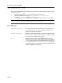
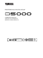
Introduction
With its high-quality 20-bit sound, the Yamaha D5000 Professional Digital Delay is the perfect
choice for studio and sound reinforcement applications.
It has four types of effect programs: DUAL (stereo) delay, SINGLE (mono) delay, FREEZE record
and playback, and S&H (sample and hold) playback. The large amount of memory allows it to
create delay lines or record samples of up to 10 seconds in duration.
The interface is simple and intuitive, with a large, easily-read LCD, allowing you to quickly
produce exactly the effect you want. It features 100 program locations for storing your favorite
effects for instant recall. For added flexibility, the D5000 can be controlled by MIDI, especially
useful with the FREEZE record and playback effect.
Please read this operation manual carefully in order to familiarize yourself with the D5000 and its
advanced features – and keep the manual in a safe place for later reference.
D5000
Precautions - 3
Precautions
Avoid excessive heat, humidity, dust, and vibration
Keep the unit away from locations where it is likely to be exposed to high temperatures or humidity
- such as near radiators, stoves, in direct sunlight, etc. Avoid locations which are subject to
excessive dirt accumulation. Extreme vibrations can cause mechanical damage.
Avoid physical shocks
Strong physical shocks can damage the unit. Handle it with care.
Do not open the unit, or attempt repairs or modifications yourself
This product contains no user-serviceable parts. Refer all maintenance to qualified Yamaha service
personnel. Opening the unit and/or tampering with the internal circuitry will void the warranty.
Make sure power is off before making or removing connections
Always turn the power OFF prior to connecting or disconnecting cables. This is important to
prevent damage to the unit itself as well as other connected equipment.
Handle cables carefully
Always plug and unplug cables - including the AC cord - by gripping the connector, not the cord.
Clean with a soft dry cloth
Never use solvents such as benzine or thinner to clean the unit. Wipe it clean with a soft, dry cloth.
Always use the correct power source
Make sure that the power source voltage specified on the rear panel matches your local AC mains
supply:
U.S. & Canadian Model: 120V AC, 60 Hz
General Model: 230V AC, 50 Hz
UK Model: 240V AC, 50 Hz
Back-up battery
The unit contains a long-life lithium battery which maintains the contents of the user memory
locations even when the unit is off. With normal use, the battery should last approximately five
years. If the battery voltage falls below a certain level, the message “WARNING LOW BATTERY” will
appear on the screen when the power is turned on. If this occurs, have the battery replaced at a
qualified Yamaha service center.
WARNING: DO NOT ATTEMPT TO REPLACE THE BATTERY YOURSELF.
D5000
4 - The front panel
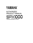
The front panel
8
DATA ENTRY
INPUT LEVEL
L
R +10
1
PARAMETER
POWER
MIX
0
-00 L
CURSOR
DRY
CLIP
-6
-12
-18
-24
-30
-36
-42
R
PROFESSIONAL DIGITAL DELAY
STORE
PROGRAM
RECALL
DELAY
FB
MOD
DUCK
PROGRAM
TRIGGER
UTILITY
BYPASS
WET
2
ON
3
4
5
6
7
9 0 A B
OFF
C
1
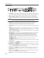
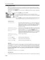
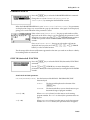
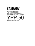
INPUT LEVEL – The two concentric rotary controls are used to adjust the level of the input
signal. The inner control adjusts the left channel and the outer control adjusts the right channel.
2
MIX – This control adjusts the amount of effect from DRY (no effect) to WET (full effect).
3
Input Level Meters (L and R) – These stereo meters consist of one eight-segment LED per
channel. The segments correspond to -42 dB, -36 dB, -30 dB, -24 dB, -18 dB, -12 dB, -6 dB, and
CLIP.
NOTE
The meters come after the A-D converters in the signal chain. Therefore, the CLIP LEDs indicate digital
distortion. The input levels should be adjusted so that the CLIP LEDs never light up.
4
PROGRAM – This 2-digit LED indicator shows the current program. When the LEDs are
flashing, this indicates that a new program has been selected but not yet recalled.
5
Screen – This backlit LCD panel displays the details of the selected parameter.
6
DATA ENTRY – The rotary encoder is used to select another program or to modify parameter
settings.
7
CURSOR – When the Program LED is lit, the [ ^ ] and [ % ] keys are used to select a program
number, the [ < ] ("STORE") key is used to store a program, and the [ > ] ("RECALL") key is used
to recall the selected program.
When the Program LED is turned off, the [ < ] , [ ^ ] , [ > ] , and [ % ] keys are used to select the
different parameters of a program.
8
PARAMETER keys – These keys allow you to select the different parameters for editing. Each
key has an LED set in it to provide a quick visual indication of the status of the unit.
The [ DELAY ] key controls the delay or freeze parameters. Each key press steps through a
sequence of display pages, allowing you to set the output level and other parameters.
The [ FB ] key controls the feedback parameters. Pressing this key more than once switches
feedback ON or OFF.
The [ MOD ] key controls the modulation. Pressing this key more than once switches
modulation ON or OFF.
The [ DUCK ] key controls the duck or gate threshold. Pressing this key more than once switches
duck ON or OFF.
9
PROGRAM key – The [ PROGRAM ] key selects one of the 100 stored programs. It has an LED
which lights when the key is pressed.
10 TRIGGER key – The [ TRIGGER ] key is used to set the tempo for delay parameters or to operate
a freeze or sample and hold program. When the delay DISPLAY UNIT (see page 11) is set to
"TEMPO", the LED will flash in time to the current tempo.
11 UTILITY key – The [ UTILITY ] key cycles through a number of display pages, allowing you to
set up various system parameters for the unit. It has an LED which lights when the key is
initially pressed.
12 BYPASS key – The [ BYPASS ] key, when pressed, causes the input signal to bypass the internal
circuitry. It has an LED which lights while BYPASS is active.
13 POWER – Press to turn the power ON. The last program will be automatically recalled.
D5000
The back panel - 5
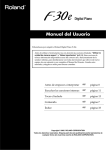
The back panel
7
6
FOOT SW
BYPASS TRIGGER
PROGRAM
INC/DEC
MIDI
OUTPUT
R
L
INPUT
R
L
IN
R
THRU OUT
12 3 4
5
L
R
L
20dB +4dB
-20dB +4dB
8
8
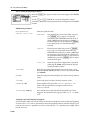
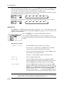
1
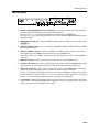
BYPASS or PROGRAM INC/DEC Footswitch Jack – The function of this jack is determined by
the FOOT SW FUNCTION parameter of the UTILITY Mode.
If it is set to BYPASS, the footswitch duplicates the function of the [BYPASS] key.
If it is set to PROGRAM, the footswitch allows you to select between a pre-determined range of
program numbers.
2
TRIGGER Footswitch Jack – A footswitch connected to this jack duplicates the function of the
[TRIGGER] key.
3
MIDI OUT/THRU Switch – This switch selects either MIDI THRU or MIDI OUT for the MIDI
OUT/THRU connector.
4
MIDI OUT/THRU Connector – When the MIDI OUT/THRU switch (3 above) is set to OUT,
data originated by the D5000 is transmitted to an external MIDI device.
When the switch is set to THRU, the connector just retransmits data received at the MIDI IN
connector.
5
MIDI IN Connector – This connector receives data from an external MIDI device.
6
OUTPUT L/R Connectors – These are the analog stereo outputs from the D5000. Both the XLRtype connectors and the TRS phone jacks are electrically balanced output connectors.
7
INPUT L/R Connectors – These are the analog stereo inputs to the D5000. Both the XLR-type
connectors and the TRS phone jacks are electrically balanced input connectors.
Use the "L" (left-channel) connector when you are using a monophonic sound source. Set the
input mode for the source with the INPUT MODE parameter for delay programs (see page 11)
or the TRACK parameter for sampler programs (see page 16 and page 20).
8
Level switches – Both the input and output connectors may be set to nominal levels of +4 dB or
-20 dB. When connecting the D5000 to other equipment, refer to the specifications of the other
units in order to match the signal levels correctly.
D5000
6 - System structure
System structure
The D5000 has three operational modes:
•
Program Select Mode - Use this mode to STORE and RECALL programs.
•
Parameter Edit Mode - This mode allows you to edit the various operational parameters,
the DELAY/FREEZE parameters, the FB (feedback) parameters, the MOD (modulation)
parameters, and the DUCK parameters.
The Parameter Edit Mode performs differently according to which program type is active.
DUAL (stereo) and SINGLE (mono) programs are delay programs. You access their
parameters with the [ DELAY ] , [ FB ] , [ MOD ] , and [ DUCK ] keys. The parameters for the
FREEZE and S&H (sample and hold) programs are accessed using the [ DELAY ] key only.
•
D5000
Utility Mode - Customize the operation of the D5000 by modifying the following
parameters: SOFTWARE PROTECT, PARAMETER DISPLAY, FOOT SW (footswitch)
FUNCTION, MIDI SETUP, MIDI CONTROLLER, MIDI BULK DUMP, PARAMETER
COPY, and REPEAT DELAY (This last parameter is only available when the program type
is DUAL or SINGLE).
Program Select Mode - 7
Program Select Mode
About the programs of the D5000
The D5000 has 100 user programs. All of the programs are user-programmable.
There are four types of programs available:
•
DUAL (stereo) Delay (refer to the diagram on page 100)
There are two delay units (A-channel and B-channel) and three taps for each unit. Create a
flanger or chorus in perfect stereo, or a ping-pong (channel-to-channel) delay.
•
SINGLE (mono) Delay
This is a single delay with six taps. It can support a delay time that is double the length of
a DUAL (stereo) program.
•
FREEZE
The input sound can be recorded and then played back in a variety of ways, including
modifying the playback speed, looping, and so on.
•
S&H (sample and hold)
Use the [TRIGGER] key or a footswitch to control the sample and hold feature. By pressing
the key or footswitch, you can sample and play-back in sequence.
Yamaha ships the D5000 with preset programs that illustrate the features of each of the four types
of programs. Refer to the list of preset programs on page 30. The preset programs are stored in
program numbers 1 to 00 (100). If you have over-written them, they can be recalled by the simple
operation detailed on page 28.
Recalling a program
Press the [ PROGRAM ] key to enter Program Select Mode. The LED on the
key will light and the LCD will display the title of the current program.
Select a new program by rotating the DATA ENTRY encoder or by
pressing the [ ^ ] or [ % ] CURSOR keys.
NOTE
Pressing and holding any of the CURSOR keys causes the key to repeat
The title of the new program is displayed on the LCD along with the
flashing "[RECALL]" message. The program number will flash on the
PROGRAM LED.
NOTE
If the FB (feedback), MOD (modulation), or DUCK parameters are active for the selected program, the
LED in the respective PARAMETER key will flash along with the program number.
D5000
8 - Program Select Mode
Press the [ > ] "RECALL" CURSOR key.
If you have not made any changes to the previous settings, it will be replaced with the new
program.
If you have made changes to the previous settings without storing them,
the unit will additionally display the message "Are you sure?" on the
LCD. Press the [ > ] "RECALL" CURSOR key again to complete your
selection. The previous program will be replaced with the new program.
If you made a mistake selecting the new program or you decide you do not want to replace the
current program, you can cancel the RECALL operation by pressing any key except the [ > ]
"RECALL" CURSOR key.
Storing a program
Press the [ PROGRAM ] key to enter Program Select Mode. The LED on the
key will light and the LCD will display the title of the current program.
Press the [ < ] "STORE" CURSOR key. The message "[STORE]" will be
displayed on the LCD along with a message showing the "From:" and
"To:" program numbers.
NOTE
If the SOFTWARE PROTECT parameter of Utility Mode is not set to OFF, the LCD will temporarily
display the message "Protected !" when you attempt to store a program.
Rotate the DATA ENTRY encoder or press the [ ^ ] and [ % ] CURSOR keys
to select the program number that you want for use to storing your
settings.
Press the [ < ] "STORE" CURSOR key again to confirm that this is what you
want to do. The message "Complete !" will briefly appear on the LCD.
Storing a program overwrites the data that was previously stored under that program number. If
you decide that you do not want to replace the program or that you made a mistake selecting the
program number, you can cancel the STORE operation by pressing any key other than the [ < ]
"STORE" CURSOR key.
D5000
Parameter Edit Mode - 9
Parameter Edit Mode
The D5000 has four types of effect program. The first two are high-quality, multi-tap digital delays,
either DUAL (stereo) or SINGLE (mono). The other two are sampling/playback recorder
programs.
Editing a delay program
To edit a delay program, press one of the PARAMETER keys, [ DELAY ] , [ FB ] , [ MOD ] , or [ DUCK ] .
The first step is usually to select the main delay parameters by pressing the [ DELAY ] key.
The D5000 features multi-tap delays. For a DUAL (stereo) delay, there are two delay units with
three taps per unit. A SINGLE (mono) delay is a single unit with six taps.
Setting the DELAY parameters
There are three display pages which you access by pressing the [ DELAY ] key:
•
Page 1: Setting the delay time, level, and pan.
•
Page 2: Setting input mode, display units, output level, and high and low pass filters.
•
Page 3: Setting the title and controller assignments.
Page 1: Setting delay time, level, and pan
You set the main parameters of your delay effect on this page. You select the number of active taps,
the length of the delay, the volume level of each tap, and its channel location in stereo.
The LCD only displays the parameters that are currently active. Use the
[ < ] , [ ^ ] , [ > ] , and [ % ] CURSOR keys to move from parameter to
parameter.
After you have selected a parameter with the CURSOR keys, you can
modify the parameter by rotating the DATA ENTRY encoder.
For example, press the [ % ] CURSOR key to move to the second tap of the
A-channel. Then rotate the DATA ENTRY encoder until the status is set to
"INV".
DELAY parameters
STATUS (OFF/NOR/INV)
Select "OFF", positive phase (NOR), or negative phase (INV). When
a tap is set to "OFF", it is inactive.
TIME
Set the length of the delay tap. If you change the DISPLAY UNIT
parameter on the next page, the value will be altered to match the
selected unit.
SECOND
SINGLE (~ 10400.00 ms) or DUAL (~ 5200.00 ms).
DISTANCE
SINGLE (~ 3536.000 m) or DUAL (~ 1768.000 m).
D5000
10 - Parameter Edit Mode
TEMPO
= (25 ~ 250 beats per minute). Select one of the
3
3
following for the Note parameter:
,
,
,
3
3
,
,
,
,
,
,
,
,
,
,
, or
.
30FRAME
SINGLE (~ 10 s 12 f 00 b) or DUAL (~ 5 s 6 f 00 b).
25FRAME
SINGLE (~ 10 s 10 f 00 b) or DUAL (~ 5 s 5 f 00 b).
24FRAME
SINGLE (~ 10 s 9 f 48 b) or DUAL (~ 5 s 4 f 64 b).
LVL (0 ~ 100%)
Set the level of the delay tap.
PAN (L16 ~ L=R ~ R16)
Set the stereo pan position of the delay tap in one of 33 steps. If
you set the modulation STATUS parameter to "PAN" (see page 13),
this setting will effect it as well.
NOTE
When TEMPO or FRAME is selected, the digits to the right of the decimal place will not be displayed.
Changing the TEMPO parameter
Use one of the following methods to modify the TEMPO parameter:
•
Manual Input
Select the parameter with the CURSOR keys, then modify the value by rotating the DATA
ENTRY encoder.
•
Tap Input ([TRIGGER] Key or Footswitch)
Set the tempo by tapping two beats on the [TRIGGER] key or by pressing two beats with a
footswitch connected to the TRIGGER Footswitch Jack on the back panel. The D5000 sets
the tempo by counting the interval between the two successive beats.
NOTE
•
It is not possible to set tap input if the DUCK parameter SOURCE is set to TRIG.KEY.
MIDI Clock Input
The tempo may be set using the MIDI clock of a connected sequencer, rhythm
programmer, or other device.
This parameter sets the TEMPO, not the delay time. You set the Note parameter for each active tap
when you edit the program. The delay time is then calculated from the TEMPO parameter and the
Note parameter.
NOTE
You can also fine tune the resulting delay TIME, but that value will be discarded any time you modify
the TEMPO or select another value for the Note parameter.
Page 2: Setting input mode, display unit, output level, and high and low pass filters
This page is used to set the overall output level for your delay. You can also apply low and high
pass filters to the effect as well as set the input mode and display units.
Press the [ DELAY ] key again to select the second display page.
Use the [ < ] , [ ^ ] , [ > ] , and [ % ] CURSOR keys to move through the
various parameters. Modify the parameter by rotating the DATA ENTRY
encoder.
D5000
Parameter Edit Mode - 11
Page 2 parameters
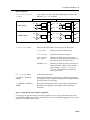
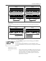
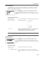
INPUT MODE (STEREO/
L-MONO)
Set the input mix mode. The following diagram illustrates the
different INPUT MODE options.
STEREO
Lch
Delay
Rch
Delay
DUAL Delay
L-MONO
Lch
Lch
Delay
Rch
Rch
Delay
Lch
Lch
PAN
Lch
SINGLE Delay
Delay
PAN
Rch
Rch
Lch
Delay
PAN
Rch
Lch
PAN
Rch
Rch
*
* The levels of the Lch and Rch input signals are halved and mixed.
DISPLAY UNIT (units)
Select the unit that will be used to display the delay time.
SECOND (ms)
Indicates the time in milliseconds.
DISTANCE (m)
Indicates the distance in meters.
TEMPO (Tempo,
Note, Time)
Indicates the delay in beats per minute.
Time(ms) is also displayed, allowing you to
fine tune the delay in milliseconds.
FRAME (s, f, b)
Indicates the delay in frames. The units are
Seconds, Frames, and Bits. There are three
types of frame: 30FRAME, 25FRAME, or
24FRAME. They differ by the number of
frames per second.
OUT LEVEL (0 ~ 100%)
Set the final output level.
HPF (20 Hz ~ 4.0 kHz or
THRU)
Set the cutoff frequency for the high pass filter for final output.
This high pass filter is applied to the signal in the digital domain,
just before the D/A converters.
LPF (400 kHz ~ 20 kHz or
THRU)
Set the cutoff frequency for the low pass filter for final output.
This filter is also applied to the signal just before the D/A
converters.
Page 3: Setting the title and controller assignments
Use this page to edit the name of your delay program. You can set two parameters that can be
controlled by a MIDI device. These parameters are set for each individual program. You can also
specify the allowable control range.
D5000
12 - Parameter Edit Mode
Press the [ DELAY ] key again to select the last display page.
Use the [ < ] , [ ^ ] , [ > ] , and [ % ] CURSOR keys to move through the
various parameters. Modify the parameter by rotating the DATA ENTRY
encoder.
Page 3: parameters
Use the [ < ] and [ > ] CURSOR keys to move along the line of text.
Change the letter under the cursor by rotating the DATA ENTRY
encoder. The available characters are shown in the following
sequence:
TITLE (16 characters)
A
B
C
D
V
W
X
Y
Z
q
r
s
t
u
/
,
.
’
%
E
F
G
H
I
J
K
L
M
N
O
P
Q
R
S
T
U
a
b
c
d
e
f
g
h
i
j
k
l
m
n
o
p
v
w
x
y
z
(
)
[
]
<
>
:
*
+
-
=
&
!
?
#
1
2
3
4
5
6
7
8
9
CTL.ASSIGN (OFF,
Parameter)
0
Select a parameter to be controlled by the MIDI control change
messages.
There are two controller channels, each of which can be assigned
any parameter of the current program (see page 25 for details).
MIN/MAX (0 ~ 100%)
Set the range within which the parameter can be modified by the
control change messages.
Adding feedback
To create a dense sounding effect, you can add feedback to each of the taps of the delay. You can
also invert the phase of the returning signal as well as filter out low and high frequency elements.
Press the [ FB ] key to select FB (feedback).
Use the [ < ] , [ ^ ] , [ > ] , and [ % ] CURSOR keys to move through the
various parameters. Modify the selected parameter by rotating the DATA
ENTRY encoder.
Press the [ FB ] key again to enable or disable feedback. The status message
in the top corner of the LCD changes from "ON" to "OFF".
Feedback parameters
D5000
STATUS (OFF/NOR/INV)
Select "OFF", positive phase (NOR), or negative (INV) phase.
TYP (→A, →B)
Select which channel (A or B) will receive the feedback. This is
only available for DUAL (stereo) delay programs.
LVL (0 ~ 100%)
Select the level of the feedback.
Parameter Edit Mode - 13
HPF (20 Hz ~ 4.0 kHz or
THRU)
Set the cutoff frequency for the high pass filter for the feedback
loop.
LPF (400 kHz ~ 20 kHz or
THRU)
Set the cutoff frequency for the low pass filter for the feedback
loop.
NOTE
You should ensure the total value of the LVL parameter of each channel for a DUAL delay or all taps
for a SINGLE delay is kept at or below 100. For example, if you have three taps active, set the values for
each tap to 30. You can vary the levels (for example: 50-30-20) as long as the total is 100 or lower.
Modulating the delay
Add modulation to the delay by changing the parameters accessed by the [MOD] key.
Press the [ MOD ] key to select MOD (modulation).
Use the [ < ] , [ ^ ] , [ > ] , and [ % ] CURSOR keys to move through the
various parameters. Modify the selected parameter by rotating the DATA
ENTRY encoder.
Press the [ MOD ] key again to enable or disable modulation. The status
message in the top corner of the LCD changes from "ON" to "OFF".
Modulation parameters
STATUS (OFF/SIN/TRI/
PAN)
Select OFF, sine waveform (SIN), triangle waveform (TRI), or
auto pan (PAN). When you select SIN or TRI, the D5000 performs
frequency modulation on the signal. If you select PAN, the auto
pan program will be effective at the pan position specified by the
DELAY parameter PAN (see page 10), and the D5000 will perform
amplitude modulation on the signal.
SPD (0.05 ~ 40.00 Hz)
Set the speed (frequency) of the modulation. If you changed the
DISPLAY UNIT parameter on the second page of the DELAY
function to TEMPO, you can select one of the following for the Note
3
3
3
3
parameter:
,
,
,
,
,
,
,
,
,
,
,
,
,
, or
.
DEP (0 ~ 100%)
Set the depth of the modulation.
PHA (0° ~ 350° in 32 steps)
Set the starting phase of the LFO (low frequency oscillator).
D5000
14 - Parameter Edit Mode
Ducking/gating the delay
When you set ducking, the delay effect is only applied to the signal when the input level drops
below the threshold you set. If you select the gate, the delay effect is applied to the signal when the
control level exceeds the threshold.
You can also use the [TRIGGER] key or a footswitch, or a MIDI Note Off/On message to trigger the
duck/gate.
Press the [ DUCK ] key to select DUCK.
Use the [ ^ ] and [ % ] CURSOR keys to move through the various
parameters. Modify the selected parameter by rotating the DATA ENTRY
encoder.
Press the [ DUCK ] key again to enable or disable the DUCK function. The
status message in the top corner of the LCD changes from "ON" to "OFF".
DUCK parameters
TYPE (DUCK/GATE)
Select the threshold activation level. DUCK means the signal passes
until the input level is above the threshold (or when a MIDI Note
Off message is received). GATE means the signal passes after the
input level is above the threshold (or when a MIDI Note On
message is received).
SOURCE (IN(L)/IN(R)/
IN(L+R)/OUT(L)/OUT(R)/
OUT(L+R)/TRIG.KEY/
MIDInote)
Select the source for the trigger signal. When you select one of the
IN or OUT settings, the duck or gate is effective depending on the
signal level. When TRIG.KEY is set, the [TRIGGER] key or a
footswitch connected to the TRIGGER Footswitch Jack on the back
panel is used to trigger the duck or gate. If MIDInote is selected,
a MIDI Note Off/On message is used as the trigger signal.
TARGET (IN(L)/IN(R)/
IN(L&R)/OUT(L)/OUT(R)/
OUT(L&R))
Select the target direction.
HOLD (2 ~ 21000 ms)
Set the hold time in milliseconds.
RELEASE (2 ~ 21000 ms)
Set the release time in milliseconds.
THRESHOLD (0 ~ 100%)
Select the duck or gate threshold level.
Duck/gate
The duck/gate can be opened by various triggers. Usually the strength of the input signal is used
as the trigger. If TYPE is set to GATE, when the input signal is higher than a certain level (threshold),
the GATE opens and the signal can pass. As soon as the input signal drops below the threshold, the
GATE closes and the signal is cut. If TYPE is set to DUCK, the signal is cut while the input signal is
higher than the threshold. As soon as the signal drops below the threshold, the DUCK is opened and
the signal can pass.
The threshold is set by the THRESHOLD parameter.
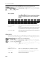
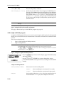
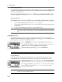
Hold and release
A short input signal, like the one shown below, would cause the GATE to open (or close in the case
D5000
Parameter Edit Mode - 15
of a DUCK) for a very short time. This can sound unnatural, especially if the GATE closes abruptly.
There are two parameters which you can adjust, HOLD and RELEASE. By setting a long HOLD time,
the gate can be kept open even after the signal has dropped below the threshold. The RELEASE
parameter specifies the length of time it takes for the gate to close, causing the signal to gradually
cut off.
Input Signal
Delay Output (TYPE set to GATE)
Threshold
Hold
Release
Other triggers
The signal level is not the only way to trigger a duck/gate. The [TRIGGER] key or a footswitch
connected to the TRIGGER Footswitch Jack on the back panel, or a MIDI Note On (for GATE) or
Note Off (for DUCK) message can also be used. The HOLD and RELEASE parameters work with any
trigger.
Re-trigger
If the DUCK/GATE is continuously triggered by any of the other sources, it may be kept from
closing. As the GATE responds to a trigger source and will open for the set HOLD time, a trigger
received while the GATE is open will act as a "re-trigger", causing the GATE to remain open.
D5000
16 - Parameter Edit Mode
Editing a sampling/playback program
To edit a sampling/playback program, press the [ DELAY ] key.
FREEZE program
The FREEZE program allows you to sample (digitally record) and playback sounds. You can record
in stereo for a maximum of 5.2 seconds or in mono for a maximum of 10.4 seconds. For playback,
you can adjust the pitch of the sample by up to ± two octaves.
NOTE
You cannot store the recorded sample. Once the power is switched OFF, or if you select another
program, the recorded sample is erased from memory.
There are four display pages:
•
Page 1: Setting the recording parameters.
•
Page 2: Setting the playback parameters.
•
Page 3: Setting the pitch and MIDI note number.
•
Page 4: Setting the title and controller assignments.
NOTE
To access the FREEZE program mode, you need to select one of the factory presets with the
PARAMETER COPY command in Utility Mode (refer to the preset list on page 30).
The [ FB ] , [ MOD ] , and [ DUCK ] keys are inactive when a FREEZE program is loaded. To access
the FREEZE display pages, use the [ DELAY ] key.
Page 1: Setting the recording parameters
This page allows you to specify the recording parameters for your freeze program.
Press the [ DELAY ] key to switch to the first page of the FREEZE program.
Use the [ ^ ] and [ % ] CURSOR keys to move through the various
parameters. Modify the selected parameter by rotating the DATA ENTRY
encoder.
FREEZE RECORD parameters
TRACK (STEREO/L-MONO)
AUTO/MAN (MANUAL/AUTO)
Select stereo or mono recording mode.
STEREO
Stereo recording for a maximum of 5.2 seconds.
L-MONO
Mono recording for a maximum of 10.4 seconds.
Set the recording method.
MANUAL
D5000
Press the [ TRIGGER ] key or step on a footswitch
connected to the TRIGGER Footswitch Jack to put
the D5000 in standby mode. Recording will start
when you press the key or step on the footswitch
again.
Parameter Edit Mode - 17
AUTO
MODE (RECORD/OVERDUB/
CAPTURE)
TRG.DLY (-1000 ~ +1000 ms)
TRG.DLY = 0
Press the [ TRIGGER ] key or step on a footswitch
connected to the TRIGGER Footswitch Jack to put
the D5000 in standby mode. Recording will start
automatically when the input signal is higher than
the specified threshold.
Select a recording mode.
RECORD
Create a new recording.
OVERDUB
Combine the new recording with existing data.
CAPTURE
The most recent input signal will be recorded for
the maximum recording time (see below).
Set the delay between triggering and the actual recording. This
parameter is only effective with the AUTO recording method. The
default value is TRG.DLY = 0 which means recording begins
simultaneously with the trigger. If a negative value is specified,
sound sampled before the trigger occurs is also stored.
Input Signal
TRG.DLY < 0
Trigger
Level
Not recorded
Trigger
Level
Start the recording
by trigger
Also recorded
Input Signal
Start the recording
by trigger
TRG.DLY
When the D5000 is in standby mode, the bar graph at the bottom of the LCD will have the message
"REC. READY" displayed on it. During the recording process, the bar graph indicates the current
status. Upon completion of the recording, the message "OK" will be displayed on the bar graph.
NOTE
If the recording mode is set to OVERDUB, the standby message will be "OVER DUB READY". If you
change the TRACK from STEREO to L-MONO (or the opposite) after recording, it is not possible to
overdub on the existing data.
If you select the CAPTURE recording mode, the D5000 begins recording
as soon as you press the [ TRIGGER ] key or step on a footswitch connected
to the TRIGGER Footswitch Jack. You cannot stop the recording until it
has recorded the default amount (5.2 seconds in stereo or 10.4 seconds in
mono) and the bar graph display has stopped moving. Recording will
continue until you press the [ TRIGGER ] key or step on the footswitch
again.
D5000
18 - Parameter Edit Mode
Page 2: Setting the playback parameters
Press the [ DELAY ] key again to switch to the second page of the FREEZE
program.
Use the [ ^ ] and [ % ] CURSOR keys to move through the various
parameters. Modify the selected parameter by rotating the DATA ENTRY
encoder.
FREEZE PLAY parameters
MODE (MOMENTARY/
CONTINU./INPUT TRG)
Select the playback mode.
MOMENTARY
The playback loop is activated while you press
the [ TRIGGER ] key or step on a footswitch
connected to the TRIGGER Footswitch Jack, or
when a MIDI Note On message is received.
Playback stops when you release the [ TRIGGER ]
key or footswitch, or a Note Off message is
received.
CONTINU.
Playback starts while you press the [ TRIGGER ]
key or step on a footswitch connected to the
TRIGGER Footswitch Jack, or when a MIDI Note
On message is received. Playback continues for
the specified number of loops. To stop playback
immediately, press the [ TRIGGER ] key or step on
the footswitch again.
INPUT TRG
When the input level is higher than a specified
threshold, the D5000 will playback the data the
specified number of times.
START (ms)
Select the start point of the playback. For stereo, select a value
between 0.00 and 5200.00. For mono, select a value between 0.00
and 10400.00.
END (ms)
Select the end point of the playback. See above for the parameter
values.
LOOP (ms)
Set the loop point. See above for the parameter values.
NUMBER (0 ~ 100)
Set the number of loops for the CONTINU. and INPUT TRG
modes. This parameter does not appear on the LCD in
MOMENTARY mode.
TRG.MASK (0 ~ 1000 ms)
Set a delay that must elapse before the playback loop can be
triggered. This parameter only appears when INPUT TRG mode
is set.
Setting the start and end points for playback
Your recorded sample may contain silence or otherwise unneeded sounds at either the beginning
or end. Use the START and END parameters to move the playback points to tailor the sample to your
needs. If you set the END parameter to a lower value than the START parameter, the sample will be
played in reverse.
D5000
Parameter Edit Mode - 19
Sample
Sample
START
END
Playback
START
END
Playback
* Sound is reversed
START
END
START
END
Playback
* Sound is reversed
Playback
Playback loop
You can set a loop point within the sample. This sets the start point for repeats after the first
playback.
Sample
START
LOOP
Sample
END
END
LOOP
START
Playback
Playback
* Sound is reversed
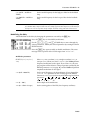
Page 3: Setting the pitch and MIDI note number
Press the [ DELAY ] key again to select the third page of the FREEZE
program.
Use the [ ^ ] and [ % ] CURSOR keys to move through the various
parameters. Modify the selected parameter by rotating the DATA ENTRY
encoder.
FREEZE PITCH parameters
PITCH (↓↓ Oct ~ Unison ~
↑↑ Oct)
Set the pitch for playback. The D5000 can adjust the pitch by plus
or minus two octaves. When you change the pitch, the playback
time of the sample is also changed. As the pitch drops, the
playback time increases, and when the pitch is increased, the
playback time is shortened.
D5000
20 - Parameter Edit Mode
FINE (-100 ~ +100)
Fine tune the pitch by ±100 cents.
BASE KEY (OFF, C 1 ~ C 6)
Specify the note that will be centre frequency for MIDI Note On
messages. The D5000 calculates the pitch change as the difference
between the BASE KEY and the note number of the pressed key.
For example, if the BASE KEY is set to "C3", then pressing C3 will
produce a Unison playback, while pressing C4 will shift the pitch
up one octave, and pressing G2 will produce a pitch change of 5
semitones down.
NOTE
If the BASE KEY parameter is set to OFF, pitch change cannot be controlled via MIDI Note On
messages.
Page 4: Setting the title and controller assignments
This page is identical to Page 3 of the DELAY program (see page 11).
S&H (sample and hold) program
A sample and hold program allows you to record a sound (sample) and then play it back repeatedly
(hold). You can record in stereo for a maximum of 5.2 seconds or in mono for a maximum of 10.4
seconds.
There are two display pages:
•
Page 1: Setting sample and hold parameters.
•
Page 2: Setting the title.
NOTE
To access the S&H (sample and hold) program mode, you need to select one of the factory presets with
the PARAMETER COPY command in Utility Mode (refer to the preset list on page 30).
The [ FB ] , [ MOD ] , and [ DUCK ] keys are inactive when an S&H program is loaded. To access the
S&H display pages, use the [ DELAY ] key.
Page 1: Setting the sample and hold parameters
Press the [ DELAY ] key to access the first display page of the S&H (sample
and hold) program.
Use the [ ^ ] and [ % ] CURSOR keys to move through the various
parameters. Modify the selected parameter by rotating the DATA ENTRY
encoder.
Sample and hold parameters
TRACK (STEREO/L-MONO)
NOR/REV
D5000
Select stereo or mono recording mode.
STEREO
Stereo recording for a maximum of 5.2 seconds.
L-MONO
Mono recording for a maximum of 10.4 seconds.
Set the playback direction. NORMAL plays the sample back in the
normal direction. REVERS plays the sample back in reverse.
Parameter Edit Mode - 21
The sample and hold function is controlled by the [ TRIGGER ] key or by a footswitch connected to
the TRIGGER Footswitch Jack.
[TRIGGER] key
or
Footswitch
STOP
[TRIGGER] key
or
Footswitch
RECORD
PLAYBACK (Loop)
[TRIGGER] key
or
Footswitch
STOP
As you press the [ TRIGGER ] key or step on the footswitch, the LCD will display the following
sequence of messages:
STOP
Indicates that the S&H function is ready to begin recording. Press
the [ TRIGGER ] key or step on the footswitch to begin recording.
RECORD
The D5000 is recording a sample. If the recording time has
exceeded the maximum, the earliest sampled data will be
overwritten by the latest sampled data. While it is recording, the
D5000 will not output any "WET" sound.
Press the [ TRIGGER ] key or step on the footswitch to stop
recording. The D5000 will start playback of the sampled data.
PLAY
The sampled data will playback in a continuous loop. Press the
[ TRIGGER ] key or step on the footswitch to stop playback.
Page 2: Setting the title
Press the [ DELAY ] key again to select the second display page.
Use the [ < ] and [ > ] CURSOR keys to move along the line of text. Change
the letter under the cursor by rotating the DATA ENTRY encoder. See
page 12 for the list of available characters.
D5000
22 - Utility Mode
Utility Mode
The [ UTILITY ] key allows you to access the system parameters. Each time you press the key, the
D5000 cycles to the next command:
SOFTWARE PROTECT
PARAMETER DISPLAY
REPEAT DELAY
FOOT SW FUNCTION
MIDI SETUP
PARAMETER COPY
MIDI BULK DUMP
MIDI CONTROLLER
Until you select one of the other modes, the LED set in the [ UTILITY ] key remains lit.
NOTE
The "REPEAT DELAY" function is not accessible when FREEZE or S&H (sample and hold) programs
are active.
SOFTWARE PROTECT
Press the [ UTILITY ] key to select the SOFTWARE PROTECT command.
Change the MODE from "OFF" to "PROGRAM" or "OPERATION" by rotating
the DATA ENTRY encoder.
When SOFTWARE PROTECT is set to "PROGRAM", it is not possible to store new programs. If you
attempt to store a program, the message "Protected !" will appear on the LCD.
When SOFTWARE PROTECT is set to "OPERATION", the following operations are inactive.
•
Recalling programs from the front panel (pressing the [ > ] "RECALL" CURSOR key).
•
Storing programs.
•
Editing program parameters.
•
Changing the status of FB, MOD, and DUCK from OFF to ON (and the opposite).
•
Turning BYPASS ON and OFF with the [ BYPASS ] key.
•
Setting tap tempo (see page 10).
•
Receiving MIDI bulk data.
•
Parameter Copy (Utility Mode).
•
Repeat Delay (Utility Mode).
If you attempt to perform one of these inactive operations, the message "Protected !" will
appear on the LCD.
NOTE
D5000
As an exception to the above,a MIDI Program Change message will perform correctly as will program
recall using the footswitch.
Utility Mode - 23
PARAMETER DISPLAY
Press the [ UTILITY ] key to select the PARAMETER DISPLAY command.
Change the MODE from "NORMAL" to "DETAIL(AUTO)" or
"DETAIL(HOLD)" by rotating the DATA ENTRY encoder.
When the PARAMETER DISPLAY is set to "DETAIL(AUTO)" or "DETAIL(HOLD)", the parameters
are displayed in a large, easy-to-read font in a pop-up sub-window. A bar graph is also displayed,
giving you a visual indication of the parameter’s status.
If the value is set to "DETAIL(AUTO)", the pop-up sub-window will be
displayed on the LCD as long as you are adjusting the parameter. It will
disappear if you press one of the [ < ] or [ > ] CURSOR buttons, or after 3
seconds have passed without further rotation of the DATA ENTRY
encoder.
If it is set to "DETAIL(HOLD)", the pop-up sub-window will remain
displayed until you press one of the [ < ] , [ ^ ] , [ > ] , or [ % ] CURSOR
buttons, or select another function.
The advantage of this feature will become apparent the first time you work on an effect in a dimlylit recording studio or concert hall.
FOOT SW (footswitch) FUNCTION
Press the [ UTILITY ] key to select the FOOT SW (footswitch) FUNCTION
command.
Use the [ ^ ] and [ % ] CURSOR keys to move through the various
parameters. Modify the selected parameter by rotating the DATA ENTRY
encoder.
FOOT SW FUNCTION parameters
BYP/PGM (PROGRAM/BYPASS) Sets the function of the BYPASS - PROGRAM INC/DEC
footswitch jack.
BYPASS
The footswitch duplicates the function of the
[ BYPASS ] key.
PROGRAM
The footswitch allows you to select between a predetermined range of program numbers.
FROM (1 ~ 00)
When PROGRAM is selected, use this item to set the starting
program number. If BYPASS is selected, this parameter does not
appear.
TO (1 ~ 00)
When PROGRAM is selected, use this item to set the last program
number. If BYPASS is selected, this parameter does not appear.
D5000
24 - Utility Mode
When the FOOT SW FUNCTION is set to PROGRAM, the D5000 switches to the next program each
time you press the footswitch. When the last program in the range (TO) is the current program,
when you press the footswitch again, it will select the first program again.
For example, if you set the FROM parameter to 70 and the TO parameter to 75, each time you press
the footswitch the program changes to the next one in order:
70
71
72
73
74
75
If you set the FROM parameter to 75 and the TO parameter to 70, the change is in reverse order:
75
74
73
72
71
70
MIDI SET-UP
The D5000 has seven MIDI program change tables set in banks "A" to "G". Each table contains a list
of MIDI program numbers and the corresponding D5000 effect program. You can customize each
table for your requirements.
Press the [ UTILITY ] key to select the MIDI SETUP command.
Use the [ ^ ] and [ % ] CURSOR keys to move through the various
parameters. Modify the selected parameter by rotating the DATA ENTRY
encoder.
MIDI SET-UP parameters
CH (OMNI, 1 ~ 16, OFF)
Select the MIDI channel for both input and output.
If you select OMNI (the default), the D5000 will receive MIDI
events on all 16 channels and transmit on channel 1.
If you select one of the channels from 1 to 16, the D5000 receives
and transmits on the selected channel.
Selecting OFF disables MIDI reception and transmission.
BANK (A ~ G)
Select a program change table.
PGM (1 ~ 128)
Select the MIDI program number. As you change the MIDI
program number by rotating the DATA ENTRY encoder, notice
how the D5000 program number changes correspondingly.
D5000 (1 ~ 00, ---)
Select the D5000 program number. You can assign any D5000
program number to the current MIDI program number. When the
D5000 receives a MIDI Program Change message with that MIDI
program number, it will switch to the corresponding D5000
program number. When "---" is selected, the D5000 will ignore
any transmissions for the corresponding MIDI program number.
NOTE
D5000
The D5000 has seven program change tables. The tables come preset from the factory with MIDI
program numbers 1 to 100 directly mapped to the D5000 program numbers 1 to 00 (100) and MIDI
program numbers 101 to 128 mapped to the D5000 program numbers 1 to 28.
Utility Mode - 25
MIDI CONTROLLER
Each D5000 program (except for Sample and Hold programs) can accept input from two MIDI
controllers. These parameters allow you to assign a MIDI controller number to the controller
channels of the programs (see page 12).
Press the [ UTILITY ] key to select the MIDI CONTROLLER command.
Use the [ ^ ] and [ % ] CURSOR keys to move through the various
parameters. Modify the selected parameter by rotating the DATA ENTRY
encoder.
MIDI CONTROLLER parameters
CONTROLLER (OFF, 1 ~ 31,
64 ~ 95, KEY NOTE,
KEY VEL., CH PRES.)
CLK (OFF/ON)
NOTE
Set a controller number for each controller assignment (1 and 2).
Control change number:
01
02
•
•
•
95
<<
<<
<<
MOD.WHEEL
BREATH
KEY NOTE
KEY VEL.
CH PRES.
Enable or disable the MIDI clock. When it is enabled, the clock of
the external MIDI device controls the TEMPO, delay time,
modulation speed, and other clock based functions.
If you set both controller assignments to the same MIDI controller number, you can control the
parameters assigned in the program simultaneously.
MIDI BULK DUMP
Press the [ UTILITY ] key to select the MIDI BULK DUMP command.
Use the [ ^ ] and [ % ] CURSOR keys to move through the various
parameters. Modify the selected parameter by rotating the DATA ENTRY
encoder.
BULK DUMP parameters
ITEM (ALL/SYSTEM/
PROGRAM/BANK)
Select the bulk data type you want to dump.
NO. (ALL, Program, or Bank)
If the ITEM parameter is set to "PROGRAM", you can select a
program number from 1 to 00 (100). Otherwise select a bank from
A to G.
D5000
26 - Utility Mode
BULK DUMP procedure
The D5000 should be correctly connected to an external MIDI device, for example, a MIDI data filer
such as the Yamaha MDF2. Set the desired parameters. Make certain that the external MIDI device
is ready to receive your data.
To execute the MIDI bulk dump request, press the [ < ] "STORE" CURSOR key. While the bulk
dump is in progress, the message "BULK OUT..." will be displayed at the bottom of the screen.
Receiving bulk data
The D5000 can also receive ("load") bulk data from another D5000, a MIDI data filer, a computer,
or other MIDI device. In order to successfully receive data, you must perform the following steps:
•
Set the SOFTWARE PROTECT parameter to OFF (see page 22).
•
Check that the MIDI channel is either OMNI or the same channel as the transmitting device
(see page 24).
•
Execute the bulk dump command on the external MIDI device.
NOTE
The received bulk data will replace all data stored in the corresponding memory locations. Before you
execute the remote bulk dump command, PLEASE BE CERTAIN THIS IS WHAT YOU INTEND TO
DO.
PARAMETER COPY
The D5000 has 100 factory preset programs available. Use this command to select one of these
programs (refer to the preset list on page 30). When you press the [ < ] "STORE" CURSOR key, the
preset program you selected is loaded for you to edit.
Press the [ UTILITY ] key to select the PARAMETER COPY command.
Use the [ % ] CURSOR key to move to the PGM parameter. Select a preset
program to copy by rotating the DATA ENTRY encoder.
To execute the copy, press the [ < ] "STORE" CURSOR key.
NOTE
In order to save your changes, you will need to execute the procedures shown on page 8.
Copying channels
If you have loaded a DUAL (stereo) program, there is are two additional parameters in the
PARAMETER COPY command that allow you to copy the data of one channel to the other.
Select the parameter "(A)-DATA" or "(B)-DATA" by rotating the DATA
ENTRY encoder. Note that the TO parameter is set to the other channel.
Use the [ % ] CURSOR key to move to the ITEM parameter. Select the data
you want to copy. The default is "ALL DATA". You can also choose
"DELAY", "FB", or "MOD".
NOTE
D5000
You can not access the TO parameter. It is either "EDIT AREA", "(B)–DATA", or "(A)–DATA"
depending on the selected FROM parameter.
Utility Mode - 27
REPEAT DELAY
This command is only available for the delay programs. It allows you to very rapidly create linear
delay programs. If you select a FREEZE or an S&H (sample and hold) program, this display page
will not appear.
Press the [ UTILITY ] key to select the REPEAT DELAY command.
Use the [ ^ ] and [ % ] CURSOR keys to move through the various
parameters. Modify the selected parameter by rotating the DATA ENTRY
encoder.
To execute the repeat delay, press the [ < ] "STORE" CURSOR key.
You can check the effect on the TIME and LVL parameter of each tap of your delay program by
pressing the [ DELAY ] key.
REPEAT DELAY parameters
REPEAT (1 ~ 6)
Set the number of repeats.
Dual
1 ~ 3 repeats.
Single
1 ~ 6 repeats.
DELAY (0 ~ 5000 ms, 0 ~
3
1700 m,
~
)
Set the delay in milliseconds (time interval between repeated
sounds), metres, or note length.
DECAY (1 ~ 100)
Set the decay in percentage (level of the last repeated sound).
When you apply the Repeat Delay by pressing the [ < ] "STORE" CURSOR key, it sets the TIME and
LVL value for the specified taps. For example:
Direct sound
Repeat 1
Repeat 2
100%
Repeat 3
Decay=40%
Delay=
3
TIME(ms)
This results in the following delay program:
NOTE
If you apply Repeat Delay to a delay program that has feedback turned on, the feedback level may be
boosted, causing an unpleasant howling. For the best results, turn the feedback off.
D5000
28 - How to initialize the D5000
How to initialize the D5000
You can reset all programs and system parameters back to their original factory settings with the
following procedure:
•
While pressing the [ < ] "STORE" CURSOR key, turn the power on.
•
The LCD will display the message "Press [RECALL] to initialize".
•
Press the [ > ] "RECALL" CURSOR key. The message "Initializing now..." will
momentarily appear on the LCD. Then the D5000 will default to Program Select Mode.
WARNING
PLEASE BE CERTAIN THAT THIS IS WHAT YOU INTEND TO DO. Any custom programs you
have created will be lost when the D5000 is reset to its factory settings.
Error Messages
D5000
WARNING LOW BATTERY
The voltage of the internal lithium battery has dropped below a
serviceable level. Take the unit to a qualified Yamaha service
center to have the battery replaced.
WARNING DATA ERROR
When the internal lithium battery is exhausted, the contents of the
internal memory will be lost. Take the unit to a qualified Yamaha
service center to have the battery replaced.
E0 ~ E3
When the power is turned on, the D5000 performs a self-test
diagnostic. If any faults are discovered, one of the error numbers
E0 to E3 will be displayed on the PROGRAM LED. Take the unit
to a qualified Yamaha service center for repair. Do not forget the
error number – the service technician needs that number in order
to speed up diagnosis of your unit.
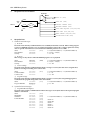
Specifications - 29
Specifications
Audio quality ("WET" circuit)
Inputs
Outputs
A/D and D/A converters
Frequency Response
20 Hz to 20 kHz +/-1.0 dB
Dynamic Range
greater than 100 dB
Hum and Noise
less than -76 dB
Distortion
less than 0.007% (max. level at 1 kHz)
Number of channels
2 (balanced)
Nominal input level
+4/-20 dBm (switchable)
Maximum input level
+24 dBm (switch at +4 dB setting)
Input impedance
20 kΩ
Number of channels
2 (balanced)
Nominal output level
+4/-20 dBm (switchable)
Maximum output level
+24 dBm (switch at +4 dB setting)
Output impedance
150Ω
A/D resolution
20-bit linear
D/A resolution
20-bit linear
Sampling frequency
50 kHz
Propagation delay
2.8 ms
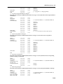
Program change
Program select (receive)
Control change
Parameter control (receive)
Note On/Off
Freeze control, Trigger (receive)
Bulk dump
System, program, bank (send & receive)
Bulk dump request
System, program, bank (receive)
Condition set-up
Bank change (receive)
MIDI clock
Tempo control (receive)
Parameter change
Parameter control (send, receive)
Parameter value request
Parameter data (receive)
USA and Canada
120 V AC, 60 Hz
General
230 V AC, 50 Hz
UK
240 V AC, 50 Hz
Number of memory locations
MIDI control
Power requirements
100 (all user-programmable)
Power consumption
25 W
Dimensions (w x d x h)
480 x 336.4 x 45.2 mm
Weight
4.7 kg
D5000
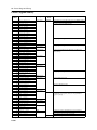
30 - Preset Program Library
Preset Program Library
Program
number
1
2
3
4
5
6
7
8
9
10
11
12
13
14
15
16
17
18
19
20
21
22
23
24
25
26
27
28
29
30
31
32
33
34
35
36
37
38
39
40
41
42
43
44
45
46
47
48
49
50
51
52
53
54
55
97
98
99
00
Title
T120 Single 15
T120 1/4 & 1/8
Double Slap
Short Single
Short Double
Medium Double
Long Single
Long Double
Long FB Double
Long FB Duck
Long FB Gate
Light Vocal
Vocal Template 1
Vocal Template 2
Vocal Template 3
Ambience
Dimension
Mod. Dimension
T120 Six 8ths
T120 Six 4ths
T60 Mod. Bounce
T120 Bounce
T120 Triplets 1
T120 Triplets 2
T120 Triplets 3
Chord Pan 1
Chord Pan 2
Perc. Pattern
Accent Pattern
Accent Loops
Spaced Pairs
Chorus Delay 1
Chorus Delay 2
Fast Wow
Mod. Bends
Stereo Chorus
Stereo Flange
Stereo Auto Pan
Stereo Tremolo
Deep Flange 1
Deep Flange 2
Wild Flange
Auto Pan Delay
Deep Tremolo
Guitar Delay
Mod. Delay 1
Mod. Delay 2
Mod. Delay 3
R->L Repeat Pan
Random Bounce
Random Echo
Light Chorus
Light Flange
Long Wow
Gated Loop
Sample & Hold
Capture Freeze
Mono Freeze
Stereo Freeze
Type
DUAL delay
Input
Mode
STEREO
Explanation
Simple delay program with single active tap. TEMPO specified.
Simple delay program with two active taps. TEMPO specified.
Basic delay program. TIME specified.
Delay program adding echo and thick effects to vocals.
SINGLE delay
DUAL delay
Delay program adding a more dimensional feeling.
SINGLE delay
Delay program applying echo reflections according to the
selected tempo.
DUAL delay
SINGLE delay
DUAL delay
Delay program adding modulation effects.
SINGLE delay
DUAL delay
Basic modulation program.
Heavily modulated program.
SINGLE delay
DUAL delay
L-MONO
Delay program for serially-connected monaural-out put
instruments, such as guitars, basses, etc. Programmed for
aggressive playing.
SINGLE delay
DUAL delay
SINGLE delay
DUAL delay
S&H
FREEZE
STEREO
Sampling program for duplicating part of a performance.
Mono freeze program records the latest sounds for 10.4 seconds.
Mono freeze program records 10.4 seconds.
Stereo freeze program records 5.2 seconds.
* As shipped from the factory, the program numbers from 56 to 96 contain the same programs as from 1 to 41.
D5000
100 - Block diagram/Schéma de principe/Blockdeagramm
Block diagram/Schéma de principe/Blockdeagramm
Single
D5000 Block Diagram (mono type)
1994.04.26
DSP
L
Delay
R
1 2 3 4 5 6
MOD
HPF
PAN
LPF
Level/Polarity
FB Level/Polarity/Type
HPF
PAN
LPF
Level/Polarity
FB Level/Polarity/Type
OUTPUT L
Lch INPUT
A/D
1
HPF
Lch MIX
BALANCE
Out Level
2
1
PAN
LPF
Level/Polarity
FB Level/Polarity/Type
HPF
Rch INPUT
PAN
LPF
OUTPUT R
Level/Polarity
FB Level/Polarity/Type
A/D
LPF
HPF
Rch
INPUT
LEVEL
2
D/A
HPF
3
HPF
3
1
LPF
Level/Polarity
FB Level/Polarity/Type
Lch
INPUT
LEVEL
2
PAN
LPF
PAN
LPF
Rch MIX
BALANCE
Out Level
Level/Polarity
FB Level/Polarity/Type
D/A
HPF
2
1
3
-20/+4dBm
3
-20/+4dBm
DELAY TIME : 0 - 10400.00ms
L INPUT R
CLIP
-6
-12
-18
-24
-30
-36
-42
LEVEL METER
INPUT MODE
BYPASS
IN
KEY
MIDI
OUT/THRU
LCD
LED
BYPASS
PGM INC/DEC
CPU
TRIGGER
FOOT SWITCH
Stereo
D5000 Block Diagram (stereo type)
1994.04.26
DSP
L
Delay(Lch)
1
2
R
3
MOD
HPF
PAN
LPF
Level/Polarity
FB Level/Polarity/Type
HPF
PAN
LPF
Level/Polarity
FB Level/Polarity/Type
OUTPUT L
Lch INPUT
A/D
1
HPF
LPF
D/A
HPF
Level/Polarity
FB Level/Polarity/Type
Lch
INPUT
LEVEL
2
PAN
LPF
Lch MIX
BALANCE
Out Level
2
1
3
3
OUTPUT R
Rch INPUT
A/D
1
HPF
LPF
D/A
HPF
Level/Polarity
FB Level/Polarity/Type
Rch
INPUT
LEVEL
2
PAN
LPF
Out Level
Rch MIX
BALANCE
PAN
LPF
Level/Polarity
FB Level/Polarity/Type
3
HPF
-20/+4dBm
LPF
FB Level/Polarity/Type
-20/+4dBm
PAN
MOD
1
Level/Polarity
2
3
Delay(Rch)
DELAY TIME : 0 - 5200.00ms
L INPUT R
CLIP
-6
-12
-18
-24
-30
-36
-42
LEVEL METER
INPUT MODE
BYPASS
IN
KEY
MIDI
OUT/THRU
CPU
LCD
LED
BYPASS
PGM INC/DEC
TRIGGER
FOOT SWITCH
D5000
2
1
3
HPF
Dimensions/Abmessungen - 101
Dimensions/Abmessungen
305.4
3.6
D:336.4
21
28.5
230.5
50
6.4
440
44
1.2
H:45.2
W:480
348
D5000
102 - MIDI Data format
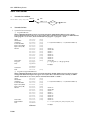
MIDI Data format
1.
Transmission Conditions
MIDI CH
OFF
BULK DATA (F0H,43H,0nH)
OMNI, 1~ 16
2.
CH = ?
MIDI OUT
Transmission Data
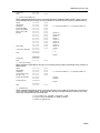
1) System Exclusive Messages
1 Program Bulk Data
When a MIDI BULK DUMP operation is performed with the "PROGRAM" ITEM selected or when a
Program Bulk Data Request message is received, the data is transmitted on the currently set MIDI channel.
If the program is set to "ALL", data is transmitted from program 1 to program 00 (100).
Status
ID Number
Sub Status
Format Number
Byte Count (MSB)
Byte Count (LSB)
Header
Data Name
Program
Data
Checksum
EOX
11110000
01000011
0000nnnn
01111110
00000010
00101000
01001100
01001101
00100000
00100000
00111000
01000001
00110110
00110011
01001101
0ppppppp
0ddddddd
...
0ddddddd
0eeeeeee
11110111
(F0H)
(43H)
(0nH)
(7EH)
(02H)
(28H)
(4CH)
(4DH)
(20H)
(20H)
(38H)
(41H)
(36H)
(33H)
(4DH)
n = 0 (channel number1) ~ 15 (channel number 16)
ASCII “L”
ASCII “M”
ASCII “ ”
ASCII “ ”
ASCII “8”
ASCII “A”
ASCII “6”
ASCII “3”
ASCII “M”
p = 1 (program 1) ~ 100 (program 00)
296 Bytes
(F7H)
2 Program Change Bank Bulk Data
When a MIDI BULK DUMP operation is performed with the "BANK" ITEM selected or when a Program
Change Bank Bulk Data Request message is received, the data is transmitted on the currently set MIDI
channel. If the bank is set to "ALL", data is transmitted from bank A to bank B.
Status
ID Number
Sub Status
Format Number
Byte Count (MSB)
Byte Count (LSB)
Header
Data Name
Bank Number
Data
D5000
11110000
01000011
0000nnnn
01111110
00000001
00000101
01001100
01001101
00100000
00100000
00111000
01000001
00110110
00110011
01010100
0zzzzzzz
0ddddddd
...
0ddddddd
(F0H)
(43H)
(0nH)
(7EH)
(01H)
(0AH)
(4CH)
(4DH)
(20H)
(20H)
(38H)
(41H)
(36H)
(33H)
(54H)
n = 0 (channel number1) ~ 15 (channel number 16)
ASCII “L”
ASCII “M”
ASCII “ ”
ASCII “ ”
ASCII “8”
ASCII “A”
ASCII “6”
ASCII “3”
ASCII “T”
z = 1 ~ 7(1=A, 2=B, 3=C, 4=D, 5=E, 6=F, 7=G)
128 Bytes
MIDI Data format - 103
Checksum
EOX
0eeeeeee
11110111
(F7H)
3 System Set-up Bulk Data
When a MIDI BULK DUMP operation is performed with the "SYSTEM" ITEM selected or when a System
Set-up Bulk Data Request message is received, the data is transmitted on the currently set MIDI channel.
Status
ID Number
Sub Status
Format Number
Byte Count (MSB)
Byte Count (LSB)
Header
Data Name
Soft Version Number
Data
Checksum
EOX
11110000
01000011
0000nnnn
01111110
00000000
00010101
01001100
01001101
00100000
00100000
00111000
01000001
00110110
00110011
01010011
00100000
0vvvvvvv
0rrrrrrr
0ddddddd
...
0ddddddd
0eeeeeee
11110111
(F0H)
(43H)
(0nH)
(7EH)
(00H)
(15H)
(4CH)
(4DH)
(20H)
(20H)
(38H)
(41H)
(36H)
(33H)
(53H)
(20H)
n = 0 (channel number1) ~ 15 (channel number 16)
ASCII “L”
ASCII “M”
ASCII “ ”
ASCII “ ”
ASCII “8”
ASCII “A”
ASCII “6”
ASCII “3”
ASCII “S”
ASCII “ ”
v=1
r=0
9 Bytes
(F7H)
4 Parameter Change
When a Parameter Value Request message is received, the parameter data is transmitted on the currently set
MIDI channel.
Status
ID Number
Sub Status
Group/Sub Group
Device Code
Parameter Number
Parameter Data
EOX
11110000
01000011
0001nnnn
00011110
00000011
0nnnnnnn
0nnnnnnn
0ddddddd
...
0ddddddd
11110111
(F0H)
(43H)
(1nH)
(1EH)
(03H)
n = 0 (channel number1) ~ 15 (channel number 16)
1st byte
2nd byte
8 bytes
(F7H)
5 All Bulk Data
When a MIDI BULK DUMP operation is performed with the "ALL" ITEM selected, the data is transmitted
on the currently set MIDI channel. All program data, all program change bank data, and all system set-up
data will be transmitted in the following order:
1 Program Bulk Data - program 1 to program 00 (100)
2 Program Change Bank Bulk Data - bank A to bank B
3 System Set-up Bulk Data
D5000
104 - MIDI Data format
3.
Reception Data and Conditions
BASE KEY
OFF
ON (C1 ~ C6)
NOTE ON (9nH)
OMNI
MIDI
CH
MIDI IN
NOTE OFF (8nH)
1~ 16
CONTROL CHANGE (BnH)
CH = ?
PROGRAM CHANGE (CnH)
BULK DUMP REQUEST (F0H,43H,2nH)
OFF
BULK DUMP (F0H,43H,0nH)
BANK CHANGE (F0H,43H,0nH)
SYSTEM REAL TIME (F8H)
4.
Reception Data
1) Channel Voice Messages
1 Note Off
Received on the currently set MIDI channel (if set to OMNI, all channels received). When a delay program
is active or a FREEZE program is set to record, the incoming data can be used as a trigger signal. The velocity
value is ignored. Data cannot be received when the BASE KEY parameter is set to OFF.
Status
Note Number
Velocity
1001nnnn
0kkkkkkk
0vvvvvvv
(9nH)
n = 0 (channel number1) ~ 15 (channel number 16)
k = 0 (C-2) ~ 127(G8)
v = 0 ~ 127
2 Note On
This message is only effective when the FREEZE program is set to playback
Status
Note Number
Velocity
1001nnnn
0kkkkkkk
0vvvvvvv
(9nH)
n = 0 (channel number1) ~ 15 (channel number 16)
k = 0 (C-2) ~ 127(G8)
v = 0 ~ 127
3 Control Change
Received on the currently set MIDI channel. When a message is received, the value of the assigned effect
parameter is changed according to the control value.
Status
Control Number
Control Value
1011nnnn
0ccccccc
0vvvvvvv
(BnH)
n = 0 (channel number1) ~ 15 (channel number 16)
c = 1 ~ 95
v = 0 ~ 127
4 Program Change
Received on the currently set MIDI channel. When a message is received, the corresponding program is
recalled from the program change table of the current bank.
Status
Program Number
1100nnnn
0ppppppp
(CnH)
n = 0 (channel number1) ~ 15 (channel number 16)
p = 0 ~ 127
2) System Exclusive Messages
1 Program Bulk Data Request
Received on the currently set MIDI channel. When a message is received, the data for the requested program
number is transmitted.
Status
ID Number
Sub Status
Format Number
D5000
11110000
01000011
0010nnnn
01111110
01001100
01001101
00100000
00100000
00111000
01000001
(F0H)
(43H)
(2nH)
(7EH)
(4CH)
(4DH)
(20H)
(20H)
(38H)
(41H)
n = 0 (channel number1) ~ 15 (channel number 16)
ASCII “L”
ASCII “M”
ASCII “ ”
ASCII “ ”
ASCII “8”
ASCII “A”
MIDI Data format - 105
Data Name
Program
EOX
00110110
00110011
01001101
0ppppppp
11110111
(36H)
(33H)
(4DH)
ASCII “6”
ASCII “3”
ASCII “M”
p = 1 (program 1) ~ 100 (program 00)
(F7H)
2 Program Change Bank Bulk Data Request
Received on the currently set MIDI channel. When a message is received, the data for the requested bank is
transmitted.
Status
ID Number
Sub Status
Format Number
Data Name
Bank Number
EOX
11110000
01000011
0010nnnn
01111110
01001100
01001101
00100000
00100000
00111000
01000001
00110110
00110011
01010100
0zzzzzzz
11110111
(F0H)
(43H)
(2nH)
(7EH)
(4CH)
(4DH)
(20H)
(20H)
(38H)
(41H)
(36H)
(33H)
(54H)
n = 0 (channel number1) ~ 15 (channel number 16)
ASCII “L”
ASCII “M”
ASCII “ ”
ASCII “ ”
ASCII “8”
ASCII “A”
ASCII “6”
ASCII “3”
ASCII “T”
z = 1 ~ 7 (1=A, 2=B, 3=C, 4=D, 5=E, 6=F, 7=G)
(F7H)
3 System Set-up Bulk Data Request
Received on the currently set MIDI channel. When a message is received, the system set-up data is
transmitted.
Status
ID Number
Sub Status
Format Number
Data Name
EOX
11110000
01000011
0010nnnn
01111110
01001100
01001101
00100000
00100000
00111000
01000001
00110110
00110011
01010011
00100000
11110111
(F0H)
(43H)
(2nH)
(7EH)
(4CH)
(4DH)
(20H)
(20H)
(38H)
(41H)
(36H)
(33H)
(53H)
(20H)
(F7H)
n = 0 (channel number1) ~ 15 (channel number 16)
ASCII “L”
ASCII “M”
ASCII “ ”
ASCII “ ”
ASCII “8”
ASCII “A”
ASCII “6”
ASCII “3”
ASCII “S”
ASCII “ ”
4 Parameter Value Request
Received on the currently set MIDI channel. When a message is received, the data for the corresponding
parameter change is transmitted.
Status
ID Number
Sub Status
Group/Sub Group
Device Code
Parameter Number
EOX
11110000
01000011
0010nnnn
00011110
00000011
0nnnnnnn
0nnnnnnn
11110111
(F0H)
(43H)
(2nH)
(1EH)
(03H)
n = 0 (channel number1) ~ 15 (channel number 16)
1st byte
2nd byte
(F7H)
5 Bank Change Request
Received on the currently set MIDI channel. When a message is received, the specified bank is called up.
Status
ID Number
Sub Status
Format Number
Byte Count (MSB)
Byte Count (LSB)
11110000
01000011
0000nnnn
01111100
00000000
00001101
(F0H)
(43H)
(0nH)
(7CH)
(00H)
(0DH)
n = 0 (channel number1) ~ 15 (channel number 16)
Condition set-up
D5000
106 - MIDI Data format
Header
Data Name
Version Number
Bank Number
Checksum
EOX
01001100
01001101
00100000
00100000
00111000
01000001
00110110
00110011
01010101
00100000
0vvvvvvv
0rrrrrrr
0zzzzzzz
0eeeeeee
11110111
(4CH)
(4DH)
(20H)
(20H)
(38H)
(41H)
(36H)
(33H)
(55H)
(20H)
ASCII "L”
ASCII "M”
ASCII " ”
ASCII " ”
ASCII "8”
ASCII "A”
ASCII "6”
ASCII "3”
ASCII "U”
ASCII " ”
v=1
r=0
z = 1 ~ 7 (1=A, 2=B, 3=C, 4=D, 5=E, 6=F, 7=G)
(F7H)
6 Program Bulk Data
The data format for transmission is the same as for "Program Bulk Data".
7 Program Change Bank Bulk Data
The data format for transmission is the same as for "Program Change Bank Bulk Data".
8 System Set-up Bulk Data
The data format for transmission is the same as for "System Set-up Bulk Data".
3) System Real Time Messages
1 Timing Clock
11111000
(F8H)
When a delay program is loaded, the tempo parameter is set automatically by the timing clock.
2 Active Sensing
11111110
(FEH)
If playback is started with a MIDI Note On message in the FREEZE program and active sensing is
interrupted, playback will be stopped.
D5000
D5000 Parameter List - 107
D5000 Parameter List
PROGRAM No.
DATE:
TITLE:
PROGRAMMER:
INPUT MODE:
STEREO . L-MONO
TYPE:
DELAY
TEMPO:
DUCK
NOTE
B
.
DUAL . SINGLE
DISPLAY UNIT: SECOND. DISTANCE. TEMPO. 30FRAME. 25FRAME. 24FRAME
A
.
TIME
LEVEL
PAN
[OFF . ON]
TYPE
1
OFF. NOR
INV
SOURCE
2
OFF. NOR
INV
TARGET
3
OFF. NOR
INV
HOLD
4
OFF. NOR
INV
RELEASE
5
OFF. NOR
INV
THRESHOLD
6
OFF. NOR
INV
OUTPUT
FB
OUT LEVEL
OFF. ON
A
B
LEVEL
1
OFF. NOR
INV
A.B
2
OFF. NOR
INV
A.B
3
OFF. NOR
INV
A.B
4
OFF. NOR
INV
A.B
5
OFF. NOR
INV
A.B
6
OFF. NOR
INV
A.B
HPF
LPF
HPF
LPF
L
R
CONTROL ASSIGN
PARAMETER
MIN
MAX
1
2
MOD
OFF. ON
A
B
NOTE
1
OFF. SIN
TRI. PAN
2
OFF. SIN
TRI. PAN
3
OFF. SIN
TRI. PAN
4
OFF. SIN
TRI. PAN
5
OFF. SIN
TRI. PAN
6
OFF. SIN
TRI. PAN
SPEED
DEPTH
PHASE
comment:
D5000
YAMAHA
[PROFESSIONAL DIGITAL DELAY]
Date:07-JUL-1994
Model D5000
MIDI Implementation Chart
Version : 1.0
+-----------------------------------------------------------------------+
|
| Transmitted
|
Recognized
|
Remarks
|
|
Function ... |
|
|
|
+-------------------+----------------+----------------+-----------------+
|Basic
Default
| x
| 1 - 16, off
| memorized
|
|Channel Changed
| x
| 1 - 16, off
|
|
+-------------------+----------------+----------------+-----------------+
|
Default
| x
| OMNIoff/OMNIon | memorized
|
|Mode
Messages | x
| x
|
|
|
Altered
| ************** | x
|
|
+-------------------+----------------+----------------+-----------------+
|Note
| x
| 0-127
|
|
|Number : True voice| ************** | x
|
|
+-------------------+----------------+----------------+-----------------+
|Velocity Note ON
| x
| x
|
|
|
Note OFF | x
| x
|
|
+-------------------+----------------+----------------+-----------------+
|After
Key's
| x
| x
|
|
|Touch
Ch's
| x
| x
|
|
+-------------------+----------------+----------------+-----------------+
|Pitch Bender
| x
| x
|
|
+-------------------+----------------+----------------+-----------------+
|
1 ~ 95 | x
| o
|
|
|
|
|
|
|
|
|
|
|
|
| Control
|
|
|
|
|
|
|
|
|
| Change
|
|
|
|
|
|
|
|
|
MIDI Implementation
|
|
|
|
|
|
|
|
|
|
|
|
|
|
|
|
|
|
|
|
|
|
|
|
|
|
|
|
|
|
+-------------------+----------------+----------------+-----------------+
|Prog
| x
| o 0 - 127
|*1
|
|Change : True #
| ***********
| x
|
|
+-------------------+----------------+----------------+-----------------+
|System Exclusive
| o
| o
|Bulk Dump
|
|
|
|
|Parameter Change |
+-------------------+----------------+----------------+-----------------+
|System : Song Pos. | x
| x
|
|
|
: Song Sel. | x
| x
|
|
|Common : Tune
| x
| x
|
|
+-------------------+----------------+----------------+-----------------+
|System
:Clock
| x
| o
|
|
|Real Time :Commands| x
| x
|
|
+-------------------+----------------+----------------+-----------------+
|Aux :Local ON/OFF | x
| x
|
|
|
:All Notes OFF| x
| x
|
|
|Mes- :Active Sense | x
| o
|
|
|sages:Reset
| x
| x
|
|
+-------------------+----------------+----------------+-----------------+
|Note: *1 = For program 1 ~ 128, program number of D5000 is
|
|
selected.
|
|
|
|
|
+-----------------------------------------------------------------------+
Mode 1 : OMNI ON, POLY
Mode 2 : OMNI ON, MONO
o : Yes
Mode 3 : OMNI OFF, POLY
Mode 4 : OMNI OFF, MONO
x : No
VS10980 R1 1 CR 94 11 500 CR Printed in Japan
P.O.Box 1,Hamamatsu,Japan