1
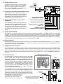
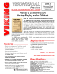
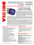
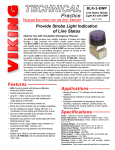
Designed, Manufactured and Supported in the USA
VIKING PRODUCT MANUAL
LDB-3
Line Status LED Strobe/
Beacon Light Kit
C O M M U N I C AT I O N & S E C U R I T Y S O L U T I O N S
October 16, 2013
Provide a Contact Closure
During Ringing and/or Off-Hook
Ideal for Use with Two-Button Emergency
Phones!
The LDB-3 Advanced Loop Detector monitors an
analog phone line for ringing and/or an off hook
condition. A built-in relay can be activated when either of these conditions are detected. This is ideal
for monitoring line status or for providing a visual
indication of such.
The LDB-3’s disable input is ideal for two-button
emergency phones, such as Viking’s E-1600-20A,
allowing “Info” button calls to be placed without activating the relay (turning on the emergency strobe
light, camera, etc.)
vated during the off time of standard ring cadence.
Three DIP switches are provided for turning ring
detection on or off, off-hook/loop detection on or
off and for selecting a ring cadence mode which allows the relay to follow ringing or to remain acti-
The LDB-3 comes complete with a 12 VDC power
adapter, and can also provide switched 12VDC .35
Amp output to power external lights, etc. during
ringing and/or off-hook conditions.
Features
Applications
• Detects ring voltage and off hook loop current
• On/off switches for ring detection and offhook/loop detection
• Control a strobe or beacon light for ring
indication
• Provide relay closures on ring and off-hook
• Screw terminal connections
• Trigger a security camera
• Selectable ring cadence mode (relay can remain on between rings)
• Trigger a tape recorder
• Phone “In Use” indicator
• Wall mountable with foam tape (included)
orscrews (not included)
• Switched 12V DC output (follows relay activation for powering strobe lights, cameras, etc.)
• One set of (NO) normally open or (NC) normally closed relay contacts provided
• Disable input, ideal for use with two-button
emergency phones (E-1600-20A), will not activate relay on “Info” calls, see DOD# 215 for
more information on the E-1600-20A
www.vikingelectronics.com
Information: (715) 386-8861
Specifications
Power: 120V AC to 12V DC adapter provided
Dimensions: 74mm x 53mm x 25mm (2.9” x 2.1” x 1.0”)
Shipping Weight: 0.4 kg (0.86 lbs)
Environmental: -26° C to 54° C (-15° F to 130° F) with
5% to 95% non-condensing humidity
Relay Contact Rating: .5A @ 125V AC/1A @ 30V DC
Maximum Current Draw Auxiliary 12V DC Output:
350mA
Minimum Loop Current: 15 mA
Disable/Info Switch Input: 50mA/80mW maximum
Ringer Equivalence: 0.5 A REN
Connections: 2 position and 11 position screw terminal
blocks
Installation
A. Mount Using Screws (not included)
Unsnap the plastic cover and remove the top
screw holding the circuit board.
VIKING©
MODEL: LDB-3
Advanced Loop Detector
Step 2.
Loosen the bottom screw and rotate the circuit
board to the left, exposing the two mounting
holes in the base.
Step 3.
Screw the base to the wall, etc. using (2) #6
flathead or sheetrock screws. Note: Make
sure the screw heads are fully driven into the
base to avoid shorting the circuit board leads.
N.C.
COM
RELAY OUTPUT
N.O.
INPUT
(INFO SWITCH)
Viking Electronics, Inc.
Hudson, WI 54016
Mounting
Holes
R
2
Z2
9
10
11
Z3
R
R4
5
R7
R9 CR
2
R8
8
Remove the backing on one side of the tape
and adhere to the LDB-3. Remove the rest of
the backing and press unit firmly to surface you
are mounting to.
1
7
6
Step 2.
5
Clean the back of the LDB-3 and the surface
you are mounting to with rubbing alcohol before mounting.
4
Step 1.
3
B. Mount Using the Included Tape
C. Wiring the Power
11
10
9
8
7
6
5
4
PHONE/TERMINAL DEVICE
3
2
LINE INPUT
1
SWITCHED 12 VDC
OUTPUT (.3A MAX)
DISABLE
2
Step 1.
(2) #6 Flathead
Screws or Sheetrock
Screws
120V AC
Internal View of the LDB-3
12V DC
Adapter
(included)
Positive
2
3
4
5
6
R
5
CR
2
R
2
1
Z3
R4
R7
R9
R8
Negative
Z2
IMPORTANT: Electronic devices are susceptible to lightning
and power station electrical
surges from both the AC outlet
and the telephone line. It is recommended that a surge protector be installed to protect against
such surges.
7
8
9
10
11
Programming
A. DIP Switches
Switch 1
ON
Internal View of the LDB-3
Switch 3 Description
Ring Detection Only (see section B).
OFF
ON
Off-Hook/Loop Current Detection Only
(see section C).
ON
ON
Ring and Off-Hook/Loop Current Detection
(see section D).
Ring Cadence Mode OFF - relay is activated only during ringing.
1
2
3
4
5
OFF
1
2
3
2
6
ON
R
5
OFF
R
2
Ring Cadence Mode ON - relay remains activated in
between rings.
CR
2
ON
Z3
Z2
Switch 2 Ring Cadence Mode (see section E)
R4
R7
R9
R8
OFF
7
8
9
10
11
B. Ring Detection Only
120V AC
Connect the incoming line to terminal block
positions 1 and 2 as shown in the diagram.
No terminal device (phone) is required. In
this manner, the LDB-3 can monitor for ringing any place along the ringing line.
12V DC
Adapter
(included)
3
4
5
6
Z3
2
R
5
1
CR
2
If the application requires off-hook (loop) and
ring detection, the LDB-3 must be placed
between the phone line and the terminal device (phone) to be monitored. Connect the
incoming line to positions 1 and 2, connect
the terminal device (phone) to positions 3
and 4.
R
2
D. Ring and Off Hook / Loop Current
Detection
Negative
Z2
The LDB-3 must be placed between the
phone line and the terminal device (phone)
to be monitored. Connect the incoming line
to positions 1 and 2 and connect the terminal
device (phone) to positions 3 and 4.
Positive
R4
R7
R9
R8
C. Off-Hook / Loop Current Detection Only
Internal View of the LDB-3
7
8
9
10
11
To C.O. Line or Analog 1
PABX/KSU extension 2
3
To Terminal Device/Phone 4
Disable/Info Switch Input 5
6
Relay
Normally Open 7
Common 8
Contacts
Normally Closed 9
Switched 12VDC 10
(350mA maximum) Output 11
E. Ring Cadence Mode
DIP switch 2 is used for switching between different ring detection modes. In the OFF position, the relay and
switched 12VDC output will activate only while ring voltage is present and will turn off between rings. In the ON
position, the relay and switched 12VDC output will remain on for up to 5.75 seconds after the ringing has stopped.
This allows the relay and 12VDC to remain on between rings of a standard ring cadence. Note: To use the Ring
Cadence Mode, ring detection MUST be enabled (DIP switch 1 - ON).
F. Relay Contacts
Normally open and normally closed relay contacts are available at terminal block positions 7, 8, 9. The contacts
are rated at .5A @ 125VAC/1A @ 30VDC. If contacts are driving an inductive load, place a suppression device
at the load to snub high voltage spikes.
G. Switched 12V DC Output
The switched 12V DC output is a low current, 12-15VDC output that is turned on only while the ring/loop detect
relay is activated. This switched power output is ideal for lighting strobe lights or powering up any device that
draws less than 350mAmps. The positive side is available at terminal position 11, and the negative side is at position 10. Once all the line and load connections have been made, plug in the 115 V AC wall adapter, and replace
the cover.
Model: xxxxxxx
P/N: xxxxxxx
S/N: XXXXXX
Viking Electronics, Inc. (715)386-8861
1531 Industrial St., Hudson, WI 54016
2
3
4
Z2
7
R
5
8
Z3
R
2
CR
2
6
R4
R7
R9
R8
5
9
10
11
LDB-3
Z2
R4
R7
R9
R8
Z3
R
2
CR
2
R
5
1 2 3 4 5 6 7 8 9 10 11
The “Disable” input can be connected to a remote switch,
contact closure, etc. for deactivating the LDB-3’s internal
relay. This can be useful to turn off the controlled device
Momentary
(strobe light, camera, etc.) Use the diagram shown at the
Switch
right. If the relay has been activated by ringing, the switch
will deactivate the relay and ringing
must stop for a minimum of 6 seconds before the relay can be re390 Ohm - 750 Ohm, 1/2 Watt Resistor
(Radio Shack part # 271-1114, 271-1115,
activated from a new incoming call.
LDB-3
1
By connecting the Disable/Info Switch input of the LDB3 to the “Info” switch of Viking’s E-1600-20A, E-160020A-EWP, E-1600-52A or E-1600-52A-EWP Emergency
Phone (not included), any outbound calls initiated from
the “Info” button will not activate the loop detect relay.
This way, only the “Help/Emergency” outbound calls will
activate the relay. Cut one of the “Info” switch wires in
half and connect each end to LDB-3 terminals 5 and 6
as shown in the diagram at the right. Note: The Disable
input is NOT polarity sensitive.
VIKING
Rear View of E-1600-20A
H. Disable Feature
271-1116, 271-1117 or equivalent)
3
Warranty
IF YOU HAVE A PROBLEM WITH A VIKING PRODUCT, CONTACT: VIKING TECHNICAL SUPPORT AT (715) 386-8666
Our Technical Support Department is available for assistance Monday 8am - 4pm and Tuesday through Friday 8am - 5pm central time. So that we can give you better service, before you call please:
1. Know the model number, the serial number and what software version you have (see serial label).
2. Have your Technical Practice in front of you.
3. It is best if you are on site.
RETURNING PRODUCT FOR REPAIR
The following procedure is for equipment that needs repair:
1. Customer must contact Viking's Technical Support Department at 715-386-8666 to obtain a Return Authorization (RA) number. The customer MUST have a complete description of the problem,
with all pertinent information regarding the defect, such as options set, conditions, symptoms, methods to duplicate problem, frequency of failure, etc.
2. Packing: Return equipment in original box or in proper packing so that damage will not occur while in transit. Static sensitive equipment such as a circuit board should be in an anti-static bag,
sandwiched between foam and individually boxed. All equipment should be wrapped to avoid packing material lodging in or sticking to the equipment. Include ALL parts of the equipment. C.O.D. or
freight collect shipments cannot be accepted. Ship cartons prepaid to: Viking Electronics, 1531 Industrial Street, Hudson, WI 54016
3. Return shipping address: Be sure to include your return shipping address inside the box. We cannot ship to a PO Box.
4. RA number on carton: In large printing, write the R.A. number on the outside of each carton being returned.
RETURNING PRODUCT FOR EXCHANGE
The following procedure is for equipment that has failed out-of-box (within 10 days of purchase):
1. Customer must contact Viking’s Technical Support at 715-386-8666 to determine possible causes for the problem. The customer MUST be able to step through recommended tests for diagnosis.
2. If the Technical Support Product Specialist determines that the equipment is defective based on the customer's input and troubleshooting, a Return Authorization (R.A.) number will be issued.
This number is valid for fourteen (14) calendar days from the date of issue.
3. After obtaining the R.A. number, return the approved equipment to your distributor, referencing the R.A. number. Your distributor will then replace the Viking product using the same R.A. number.
4. The distributor will NOT exchange this product without first obtaining the R.A. number from you. If you haven't followed the steps listed in 1, 2 and 3, be aware that you will have to
pay a restocking charge.
LIMITED WARRANTY
Viking warrants its products to be free from defects in the workmanship or materials, under normal use and service, for a period of one year from the date of purchase from any authorized Viking
distributor or 18 months from the date manufactured, which ever is greater. If at any time during the warranty period, the product is deemed defective or malfunctions, return the product to Viking
Electronics, Inc., 1531 Industrial Street, Hudson, WI., 54016. Customer must contact Viking's Technical Support Department at 715-386-8666 to obtain a Return Authorization (R.A.) number.
This warranty does not cover any damage to the product due to lightning, over voltage, under voltage, accident, misuse, abuse, negligence or any damage caused by use of the product by the
purchaser or others. This warranty does not cover non-EWP products that have been exposed to wet or corrosive environments.
NO OTHER WARRANTIES. VIKING MAKES NO WARRANTIES RELATING TO ITS PRODUCTS OTHER THAN AS DESCRIBED ABOVE AND DISCLAIMS ANY EXPRESS OR IMPLIED WARRANTIES OR MERCHANTABILITY OR FITNESS FOR ANY PARTICULAR PURPOSE.
EXCLUSION OF CONSEQUENTIAL DAMAGES. VIKING SHALL NOT, UNDER ANY CIRCUMSTANCES, BE LIABLE TO PURCHASER, OR ANY OTHER PARTY, FOR CONSEQUENTIAL, INCIDENTAL, SPECIAL OR EXEMPLARY DAMAGES ARISING OUT OF OR RELATED TO THE SALE OR USE OF THE PRODUCT SOLD HEREUNDER.
EXCLUSIVE REMEDY AND LIMITATION OF LIABILITY. WHETHER IN AN ACTION BASED ON CONTRACT, TORT (INCLUDING NEGLIGENCE OR STRICT LIABILITY) OR ANY OTHER
LEGAL THEORY, ANY LIABILITY OF VIKING SHALL BE LIMITED TO REPAIR OR REPLACEMENT OF THE PRODUCT, OR AT VIKING'S OPTION, REFUND OF THE PURCHASE PRICE AS
THE EXCLUSIVE REMEDY AND ANY LIABILITY OF VIKING SHALL BE SO LIMITED.
IT IS EXPRESSLY UNDERSTOOD AND AGREED THAT EACH AND EVERY PROVISION OF THIS AGREEMENT WHICH PROVIDES FOR DISCLAIMER OF WARRANTIES, EXCLUSION OF
CONSEQUENTIAL DAMAGES, AND EXCLUSIVE REMEDY AND LIMITATION OF LIABILITY, ARE SEVERABLE FROM ANY OTHER PROVISION AND EACH PROVISION IS A SEPARABLE
AND INDEPENDENT ELEMENT OF RISK ALLOCATION AND IS INTENDED TO BE ENFORCED AS SUCH.
Product Support: (715) 386-8666
Due to the dynamic nature of the product design, the information contained in this document is subject to change without notice. Viking Electronics, and its affiliates
and/or subsidiaries assume no responsibility for errors and omissions contained in this information. Revisions of this document or new editions of it may be issued
to incorporate such changes.
4
DOD# 409
Printed in the U.S.A.
ZF301620 Rev D