1
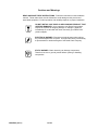
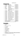
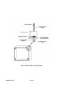
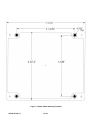
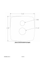
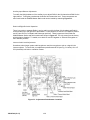
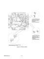
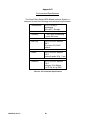
INSTALLATION MANUAL SERIES 9800 MARINE INTERCOM SYSTEM 19532P-62 (03-11) 2011 David Clark Company Incorporated Table of Contents Cautions and Warnings ................................................................................................... 1 Parts/Tools List ............................................................................................................... 2 System Overview ............................................................................................................ 3 1. Mounting the Master Station .................................................................................... 5 2. Mounting the Panel Display ................................................................................... 10 3. System Cables ....................................................................................................... 15 4. Radio Cables ......................................................................................................... 19 5. Remote PTT (Optional) .......................................................................................... 20 6. Power Cable .......................................................................................................... 22 7. Captain's Priority Switch (Optional) ........................................................................ 24 8. Auxiliary Audio Connection (Optional) .................................................................... 25 9. Connecting Headsets and PTT Switches ............................................................... 27 10. Operation ............................................................................................................... 28 11. Testing and Troubleshooting .................................................................................. 31 Appendix A....................................................................................................................A1 C98-50LN – 50-foot System Cable Appendix B....................................................................................................................B1 P/N 40688G-47 Waterproof Fuse Kit Installation Instructions Appendix C .................................................................................................................. C1 Master Station Adjustments Appendix D .................................................................................................................. D1 Environmental Specifications List of Figures Figure Page 1 Typical 4- Person Layout ............................................................................... 4 2 Master Station Mounting Diagram .................................................................. 6 3 Master Station Mounting Template ................................................................ 7 4 Master Station Connections ........................................................................... 9 5 Panel Display Control .................................................................................. 10 6 C98-20PD Panel Display Cable ................................................................... 10 7 Panel Display Mounting Diagram ................................................................. 11 8 Panel Display Mounting Template................................................................ 13 9 C98-XXLN In-Line Style System Cable ........................................................ 15 10 C98-XXPN Panel Mount System Cable ....................................................... 15 11 40894G-XX Panel Mounting Template ......................................................... 17 12 C98-20RD Radio Cable ............................................................................... 19 19532P-62 (03-11) i List of Figures (continued) Figure Page 13 C98-15RS Remote PTT Cable ..................................................................... 20 14 C98-20PW Cable w/40688G-47 2-Amp Fuse Kit ......................................... 22 15 C98-20PW Power Cable .............................................................................. 23 16 C98-20AX Auxiliary Audio Cable.................................................................. 25 17 Audio Isolation Transformer Circuit .............................................................. 26 18 Headset with Body PTT Switch .................................................................... 27 19 Panel Display Control .................................................................................. 28 A1 C98-50LN Connector Pin Diagram...............................................................A2 A2 C98-50LN Proper use of Compression Ring ................................................A2 A3 C98-50LN Proper Assembly of Connector onto Cable .................................A2 B1 Proper Assembly of Fuse Holder Kit (40688G-47) .......................................B1 C1 Adjustment Potentiometer Locations (U9800S)........................................... C2 C2 Jumper Locations (U9800S) ....................................................................... C3 List of Tables Table Page 1 System Components...................................................................................... 3 2 Radio Cable Wire Color Functions ............................................................... 19 3 C98-20AX Wire Color Chart ......................................................................... 26 4 Panel Display Menu Options ........................................................................ 28 5 Behavior when Captain's Priority is Disabled ............................................... 30 6 Behavior when Captain's Priority is Enabled ................................................ 30 7 Troubleshooting ........................................................................................... 32 A1 Connector Kit Parts and Tools Required C98-50LN .....................................A1 A2 Connector Pins and Wire Colors C98-50LN .................................................A2 D1 Environmental Specifications ...................................................................... D1 19532P-62 (03-11) ii Cautions and Warnings READ AND SAVE THESE INSTRUCTIONS. Follow the instructions in this installation manual. These instructions must be followed to avoid damage to this product and associated equipment. Product operation and reliability depends on proper installation. DO NOT INSTALL ANY DAVID CLARK COMPANY PRODUCT THAT APPEARS DAMAGED. Upon unpacking your David Clark product, inspect the contents for shipping damage. If damage is apparent, immediately file a claim with the carrier and notify your David Clark product supplier. ELECTRICAL HAZARD - Disconnect electrical power when making any internal adjustments or repairs. All repairs should be performed by a representative or authorized agent of the David Clark Company. STATIC HAZARD - Static electricity can damage components. Therefore, be sure to ground yourself before opening or installing components. 19532P-62 (03-11) 1 of 32 Parts/Tools List Supplied by David Clark q q q q q q q q q q q q q q q q q q q q q q q q q q q q U9800S U9810PD U9810BS U9811BS H9832 H9842 H9842BK H9842SK Master Station (P/N 40898G-01) Panel Display (P/N 40879G-01) Body Switch PTT (P/N 40895G-03) Body Switch PTT/Cell Phone (P/N 40895G-02) Headset OTH (P/N 40896G-02) Headset BTH (P/N 40897G-03) Headset BTH(black) (P/N 40897G-04) Headset BTH with Momentary (P/N 40897G-06) Mic Switch (black) H9842TM Headset BTH with Throat Mic (P/N 40897G-08) (black) C98-15RS Remote PTT Switch (P/N 40800G-02) C98-20PW Cable Assy, Power (P/N 40892G-02) C98-20PD Cable Assy, Panel Display (P/N 40892G-03) C98-10LN System Cable, In-Line, 10ft (P/N 40893G-07) C98-15LN System Cable, In-Line, 15ft (P/N 40893G-08) C98-20LN System Cable, In-Line, 20ft (P/N 40893G-09) C98-25LN System Cable, In-Line, 25ft (P/N 40893G-10) C98-30LN System Cable, In-Line, 30ft (P/N 40893G-11) C98-50LN System Cable, In-Line, 50ft (P/N 40893G-12) C98-10PN System Cable, Panel, 10ft (P/N 40894G-04) C98-20PN System Cable, Panel, 20ft (P/N 40894G-05) C98-30PN System Cable, Panel, 30ft (P/N 40894G-06) C98-20AX Cable Assy, Auxiliary (P/N 40892G-04) C98-20RD Cable Assy, Radio (P/N 40892G-01) C98-15CP Cable Assy, Multi Use, 15 ft. (P/N 40892G-05) C98-30CP Cable Assy, Multi Use, 30 ft. (P/N 40892G-10) Master Station Mounting Kit (P/N 40688G-63) C98-XXPN Mounting Kit (P/N 40688G-64) Cable Fittings & Nuts are included with System Cables Customer Supplied q q q q q q q q q q q q q q q q q Screwdriver selection Pen/Pencil Drill Drill Bits (5/8”, 5/32”, 27/32”) 1 1/4” hole-saw Wire strippers Wire cutters Needle-Nose pliers Grommet assortment Wire tie assortment Tape Measure X-Acto/Razor knife Soldering Iron/Solder Heat gun Radio adapters (for interfacing to radios—supplied by radio manufacturer) Pin assignments for each radio adapter (supplied by radio manufacturer) Heat Shrink tubing assortment 1/8” to 3/8” 19532P-62 (03-11) 2 of 32 System Overview The Series 9800 Marine Intercom System is a weather-resistant communication system designed for the marine environment. It allows a captain, co-captain, and up to four passengers (six positions total) to communicate with each other over the intercom, and two of the members (captain and co-captain) to communicate over two mobile radios. Also available is an option to interface a third audio source such as a Stereo, CD player, or any other listen-only radio. Primary components of the system are indicated in Table 1. In addition, a basic layout of a 4-position system is shown in Figure 1. Component Part and Model Numbers Master Station Master Station - Model Number U9800S Remote Panel Display Control Panel Display - Model Number U9810PD Over-the-Head Style – Model Number H9832 Behind-the-Head Style – Model Number H9842 Headsets (up to 6) Behind-the-Head Style – Model Number H9842BK Behind-the-Head Style with Momentary Mic Switch – Model Number H9842SK Note: H9842SK headsets are not recommended for Captain and Co-Captain positions. Behind-the-Head Style with Throat Mic – Model Number H9842TM In-Line System Cable (1 per headset) 10 foot Length – Model C98-10LN 15 foot Length – Model C98-15LN 20 foot Length – Model C98-20LN 25 foot Length – Model C98-25LN 30 foot Length – Model C98-30LN 50 foot Length – Model C98-50LN (connector unassembled for custom length) Cables Remote PTT Body Switches Panel Mount System Cable (1 per headset) 10 foot Length – Model C98-10PN 20 foot Length – Model C98-20PN 30 foot Length – Model C98-30PN Power Cable – Model Number C98-20PW (1 per master station) Panel Display Cable – Model Number C98-20PD (1 per Panel Display, maximum of 1) Captain’s Priority Cable – Model Number C98-15CP or C98-30CP (optional, maximum of 1) Auxiliary Cable – Model Number C98-20AX (1 per Aux input, maximum of 1 ) Radio Cable – Model Number C98-20RD* (1 per Radio Input, maximum of 2) * Other versions available. Contact factory with radio make and model. Remote PTT Switch - Model Number C98-15RS (Optional, Maximum of 2) Remote PTT Cable – Model Number C98-15CP or C98-30CP (Optional, Maximum of 2) Body Switch, PTT, 15’ coil cord - Model Number U9810BS (1 per radio transmit headset, maximum of 2) Body Switch, PTT w/cell phone connector, 15’ coil cord - Model Number U9811BS Table 1: System Components 19532P-62 (03-11) 3 of 32 Figure 1: Typical 4-Person Layout 19532P-62 (03-11) 4 of 32 1. Mounting the Master Station Parts/Tools Required q q q q q q q q U9800S Series 9800 Intercom System Master Station (40898G-01) Master Station Mounting Kit (40688G-63) o 4 neoprene washers o 4 Stainless steel screws o 4 Nylon washers o 4 Stainless steel washers o 4 Stainless steel nuts Pencil/Pen Drill 7/32-inch Drill Bit Drilling Template (Figure 3) Philips-head screwdriver 11/32-inch nut driver or wrench Procedure Location Considerations Select a location on a flat surface that is out-of-the-way, and provides adequate room to attach all cables. Be sure to allow for internal access, as adjustments may be necessary. The Master Station is weather resistant, however the mounting location should be chosen to minimize direct exposure to the elements. Mounting q Using the mounting template in Figure 3, mark and drill the (4) 7/32-inch holes through the mounting surface. q Remove the cover and position the Master Station on the mounting surface and confirm mounting holes. q Mount the Master Station using the hardware provided. Slide nylon washer over each screw before using. Place a neoprene washer between the Master Station and the surface where each screw is located. Use a stainless-steel washer on the back side of the surface under each nut. Secure tightly with a stainless-steel lock-nut. See Figure 2. q The installer may wish to leave the cover removed from the Master Station, as internal adjustments may be necessary later during the installation. Be sure to replace cover and tighten the four screws when adjustments are completed. 19532P-62 (03-11) 5 of 32 Figure 2: Master Station mounting diagram 19532P-62 (03-11) 6 of 32 Figure 3: Master Station Mounting Template 19532P-62 (03-11) 7 of 32 This Page Left Intentionally Blank 19532P-62 (03-11) 8 of 32 Figure 4: Master Station Connections 19532P-62 (03-11) 9 of 32 2. Mounting the Panel Display The Panel Display is the control center for the David Clark Series 9800 Marine Intercom System. From here the user can adjust volume and sensitivity levels, as well as select which radio is active for transmitting. See section 10. Operation for complete details. Parts/Tools Required q q q q q q q U9810PD Series 9800 Intercom System Panel Display (40879G-01) (Figure 5) o Mounting nut and 3x3-inch gasket included C98-20PD Panel Display Cable (40892G-03) (Figure 6) Drill 1 1/4” Hole-saw Drilling template (Figure 8) Pen/Pencil Wire ties MARINE INTERCOM MODE TX1 TX2 Figure 5: Panel Display Control Figure 6: C98-20PD Panel Display Cable 19532P-62 (03-11) 10 of 32 Procedure q Determine the location for the Panel Display. The Panel Display should be mounted on a flat surface that is visible and accessible to the captain and co-captain. The surface can range in thickness from 1/32 to 7/8 inches. See Figure 7. q Be sure there is at least 6-inches of room behind the panel to attach and route the C98-20PD Panel Display Cable. q Using the drilling template in Figure 8, mark the location for the 1 1/4” hole on the mounting surface. q Drill the 1-1/4” hole using the hole-saw. q Place the provided 3”x3” gasket over the threaded bushing of the Panel Display and mount the Panel Display as shown in Figure 7. q Do not over-tighten but make sure that the Panel Display will not rotate and sealing gasket is compressed tightly. q Attach the C98-20PD cable to the Panel Display. q Connect the cable to the Master Station’s connector labeled “Panel Display” (see Figures 1&4). To connect the cable to the Master Station, align keyways and push. Then firmly turn collar clockwise until it locks into place. Pull back gently on the cable to ensure connector is properly locked. q Use plastic cover to protect the Panel Display when it is not in use. Figure 7: Panel Display Mounting Diagram 19532P-62 (03-11) 11 of 32 This Page Left Intentionally Blank 19532P-62 (03-11) 12 of 32 Figure 8: Panel Display Mounting Template (Overall Clearance with Cover 4-1/2" Square) 19532P-62 (03-11) 13 of 32 This Page Left Intentionally Blank 19532P-62 (03-11) 14 of 32 3. System Cables System Cables interface David Clark Series H9800 Headsets to the Series 9800 Marine Intercom System. For convenience, there are two types of System Cables available, In-Line and Panel-Mount. The Series 9800 Intercom System can accommodate up to six headsets. Parts/Tools Required q q q q q q C98-XXLN In-Line style system cable (XX is length in ft, see Table 1 for available lengths) o Cable fitting & nut included (Figure 9) C98-XXPN Panel-Mount style system cable (XX is length in ft, see Table 1 for available lengths) o Template and mounting hardware included (Figure 10) Drill & Bit(s) (27/32” for In-Line, 7/8" & 5/32” for Panel-Mount) Philips-head screwdriver Adjustable wrench (for In-Line) 5/16-inch wrench or nut driver (for Panel-Mount) Figure 9: C98-XXLN In-Line Style System Cable Customer Panel Up to 7/8” Figure 10: C98-XXPN Panel Mount System Cable 19532P-62 (03-11) 15 of 32 Procedure • Special note for C98-50LN: See Appendix A for connector assembly instructions . • For In-Line installation: • q Determine the location for the System Cable/Fitting. Maximum panel thickness is 7/32”. q Drill 27/32” hole in panel where System Cable is to be installed. q Remove mounting nut from cable fitting and put in a safe place. q Snake cable through hole from the outside (headset side) in. q Slide mounting nut back onto cable and snugly tighten the cable fitting, leaving 3-4 inches of length between cable fitting and headset end of cable q Route the cable between each Headset/Station and the Master Station. The cable should be routed using under-deck conduits and be as far as possible from radio antenna coax cables and anywhere water may collect. Coil and tie-wrap any excess cable. q Determine which position this Headset/Station is (Captain/Co-Captain/Passenger) and connect System Cable to the Master Station. See Figures 1&4 for connector locations. q To connect cable to master station, align keyways and push. Then firmly turn collar clockwise until it locks into place. Pull back gently on the cable to ensure connector is properly locked. q Repeat this procedure for each C98-XXLN cable to be installed. For Panel-Mount installation: q Determine location for the panel to be mounted. q Use the template in Figure 11 to mark and drill the five holes in the surface. Use a 7/8” bit for the center hole and a 5/32” bit for the four corners. q Route the cable through the 7/8” center hole all the way to the Master Station. The cable should be routed using under-deck conduits and be as far as possible from radio antenna coax cables and anywhere water may collect. Coil and tie-wrap any excess cable. q Secure Panel to surface using the screws, washers, and nuts provided. See Figure 10. q Determine which position this Headset/Station is (Captain/Co-Captain/Passenger) and connect System Cable to the Master Station. See Figures 1&4 for connector locations. q To connect the cable to the Master Station, align keyways and push. Then firmly turn collar clockwise until it locks into place. Pull back gently on the cable to ensure connector is properly locked. q Repeat this procedure for each C98-XXPN cable to be installed. 19532P-62 (03-11) 16 of 32 5/32 TYP 1.500 1.500 7/8 Figure 11: 40894G-XX Panel mounting template (Overall Clearance 2" Square) 19532P-62 (03-11) 17 of 32 This Page Left Intentionally Blank 19532P-62 (03-11) 18 of 32 4. Radio Cables The C98-20RD Radio Cables are used to interface a marine or mobile radio to the Series 9800 Marine Intercom System. One end of the cable connects to the Master Station and the other end connects to the radio. Since the interface is different for each type of radio, the C98-20RD is left un-prepared at the radio end so that the installer may choose the correct interface. Note: This procedure applies only to the C98-20RD Radio Cable. Contact factory if assistance with other cables is needed. Parts/Tools Required q q q C98-20RD Radio Cable (One for each radio to be interfaced) Mating connector and pin information for radio interface (installer provided) o Wire Crimping/Cutting/Soldering/etc tools (depends on radio interface) Wire ties Figure 12: C98-20RD Radio Cable Procedure q Determine the path of the cable between each radio and the Master Station. The radios should already be installed and tested. The cable should be routed using under-deck conduits and be as far as possible from radio antenna coax cables and anywhere water may collect. q Route the cable. The connector end connects to the Master Station. Leave enough excess cable at the radio end for preparation of radio interface. q Determine which radio number this radio is (i.e., Radio 1/Radio 2) and connect Radio Cable to the Master Station. See Figures 1&4 for connector locations. q To connect the cable to the Master Station, align keyways and push. Then firmly turn collar clockwise until it locks into place. Pull back gently on the cable to ensure connector is properly locked. q Prepare the radio interface in accordance with manufacturer’s instructions. See Table 2 for C98-20RD Radio Cable wire color functions. The end of this cable is stripped and tinned at the factory. Due to the difficulty in soldering to these conductors, it is recommended that any extra cable be coiled up rather than cut. q Repeat this procedure for Radio 2 (if applicable). Pin 1 2 3 4 5 6 Color Red White Orange Brown Green Black Shield Function Mic Hi (+) Mic Lo (-) PTT Hi (+) PTT Lo (-) Ear Hi (+) Ear Lo (-) Shield (To PTT Lo or Mic Lo) Table 2: Radio Cable Wire Color Functions 19532P-62 (03-11) 19 of 32 5. Remote PTT (Optional) The Captain and Co-Captain positions provide the option for a Remote PTT switch, which can be mounted in a convenient location. The C98-15RS cable is finished with a connector on one end and a molded, waterproof switch on the other end, and a compression fitting. Note: This procedure applies to the C98-15RS Remote PTT Cable with built-in switch. Alternately, the C98-15CP or C98-30CP multi-use cables can be used for remote PTT. The multi-use cables facilitate connection to user supplied marine grade switches. Parts/Tools Required q q q q C98-15RS Remote PTT Cable (40800G-02) – Captain/Co-Captain positions only. Wire ties Drill & 27/32" Bit Adjustable wrench Figure 13: C98-15RS Remote PTT Cable Procedure q Determine the locations of each PTT switch. Choose location based on customer requirement and accessibility. A common location for the Remote PTT is wire-tied to the throttle. q Determine the path of the cable between each PTT switch location and the Master Station. The cable should be routed using under-deck conduits and be as far as possible from radio antenna coax cables and anywhere water may collect. q Determine the location for the compression fitting. Maximum panel thickness is 7/32". q Drill 27/32" hole in panel where compression fitting is to be installed. q Remove mounting nut from compression fitting and put in a safe place. q Snake cable through hole from the outside (switch side) in. q Slide mounting nut back onto cable and snugly tighten the cable fitting. q Route the cable. Use wire ties where necessary. q Determine which Remote PTT switch this cable corresponds to (Captain or Co-Captain) and connect to the Master Station. See Figures 1&4 for connector locations. q To connect the cable to the Master Station, align keyways and push. Then firmly turn collar clockwise until it locks into place. Pull back gently on the cable to ensure connector is properly locked. q Repeat this process for the 2 Remote PTT switch (if applicable). 19532P-62 (03-11) nd 20 of 32 Alternate Remote PTT Procedure: Parts/Tools Required q q q q q q q C98-15CP or C98-30CP Multi Use Cable (40892G-05 or 40892G-10) SPST or SPDT switch (user supplied) Marine grade connectors (as needed, for user supplied switch) Wire cutters and wire strippers Drill and drill bit (size dependant on switch used) Heat-shrink tubing Wire ties Procedure q Determine the location of the PTT switch. q Drill a hole the appropriate size for the switch selected. q Route the C98-15CP or C98-30CP cable from the Master Station to the switch location. The cable should be routed using under-deck conduits and be as far as possible from radio antenna coax cables and anywhere water may collect. Use wire ties where necessary. q Determine which Remote PTT switch this cable corresponds to (Captain or Co-Captain) and connect to the Master Station. See Figures 1&4 for connector locations. q To connect the cable to the Master Station, align keyways and push. Then firmly turn collar clockwise until it locks into place. Pull back gently on the cable to ensure connector is properly locked. q Route the unprepared end of the cable through the hole you drilled. Route from the backside. q Prepare the cable and connect to the user supplied switch in accordance with switch manufacturer’s instructions. o Do not connect the shield, instead cut it flush to the jacket. o The cable must be connected to the NORMALLY OPEN contacts of the switch. q When the switch is closed, PTT is active. q Mount the switch in the hole. 19532P-62 (03-11) 21 of 32 6. Power Cable The C98-20PW is a 20-foot cable used to provide power to the Series 9800 Marine Intercom System. It has a connector on one end and the other end requires the installer to prepare. It is important to choose a power “pick-off” point which can provide 2 amperes of current at a voltage between 11-30VDC. Direct connection to a 2-Amp fuse/circuit-breaker is preferred. Parts/Tools Required q q q q q q q C98-20PW Power Cable (40892G-02) o Includes David Clark 2-Amp Fuse kit (40688G-47) Power pick-off point (circuit breaker/Fuse box, 11-30VDC) Soldering iron/Solder Wire terminals Wire cutters/ Wire strippers Tape Measure Wire ties Figure 14: C98-20PW Cable with 40688G-47 2-Amp Fuse kit Procedure q Determine the location of a 2-Amp circuit breaker to be used and how to connect to it (solder, screw terminals, lugs, etc). q If only a higher-amperage circuit breaker is available, it may be used, but the David Clark 2-Amp Fuse Kit must also be used. q Determine the location of the 11-30VDC and Ground pick-off points. q Determine the path of the cable between the power source and the Master Station. The cable should be routed using under-deck conduits and be as far as possible from radio antenna coax cables and anywhere water may collect. q Measure the length of cable necessary, adding 3 ft as a service loop. q If necessary, trim the length of the cable to the length you just determined in the previous step. Be sure to trim the UN-PREPARED end of the cable. q Route the cable. Use wire ties where necessary. 19532P-62 (03-11) 22 of 32 q Connect the cable to the jack on the Master Station labeled “Power Cable”, see Figures 1&4. To connect the cable to the Master Station, align keyways and push. Then firmly turn collar clockwise until it locks into place. Pull back gently on the cable to ensure connector is properly locked. Before continuing, ensure that power is shut off to the point where you are going to connect the power cable! q Using the wire cutters and wire strippers, prepare the end of the cable as necessary for your installation (Figure 15). q If using the David Clark 2-Amp Fuse Kit, please see Appendix B for assembly instructions. q Connect the cable to the power source o o q Connect the RED to the positive (+) terminal. Connect the BLACK and SHIELD to the negative (-) terminal. Do not turn on power at this time, wait until Section 11. Testing & Troubleshooting. RED BLACK/SHIELD Figure 15: C98-20PW Power Cable 19532P-62 (03-11) 23 of 32 To 2 amp circuit breaker/fuse 7. Captain’s Priority Switch (Optional) The Captain’s Priority switch allows for the Captain to isolate himself along with Radio 1 and Radio 2 from the Co-Captain and the Passengers. When this switch is ON, the Captain will have exclusive access to Radio 1 and Radio 2. See section 10. Operation for complete details. Parts/Tools Required q q q q q q q C98-15CP or C98-30CP Multi Use Cable (40892G-05 or 40892G-10) SPST/SPDT Switch (user supplied) Marine grade connectors (as needed, for user supplied switch) Wire cutters/Wire strippers Drill/Drill Bits (size dependant on switch used) Heat-shrink tubing Wire ties Procedure q Determine the location for the Captain’s Priority switch. Choose a location where the Captain will have access to it, but it will not be accidentally triggered. q Drill a hole the appropriate size for the switch selected. q Route the C98-15CP or C98-30CP cable from the Master Station to the switch location. The cable should be routed using under-deck conduits and be as far as possible from radio antenna coax cables and anywhere water may collect. Use wire ties where necessary. q Connect the cable to the Master Station’s jack labeled “Captain’s Priority”, see Figures 1&4. To connect the cable to the Master Station, align keyways and push. Then firmly turn collar clockwise until it locks into place. Pull back gently on the cable to ensure connector is properly locked. q Route the unprepared end of the cable through the hole you drilled from the backside. q Prepare the cable and connect to the user supplied switch in accordance with switch manufacturer's instructions. o Do not connect the shield, instead cut it flush to the jacket. o The cable must be connected to the NORMALLY OPEN contacts of the switch. q When the switch is closed, the Captain’s Priority feature is active. q Mount the switch in the hole. 19532P-62 (03-11) 24 of 32 8. Auxiliary Audio Connection (Optional) The Auxiliary Audio connection is intended for use with line-level devices only. Typical connections include a portable CD/MP3 player’s headphone jack or the “Preamp Output” RCA jacks on a car/marine stereo. IMPORTANT: To connect to the External Speaker terminals of a communications or weather radio that has balanced audio output, an external transformer MUST be used to prevent possible damage to the radio and/or the Series 9800 Marine Intercom. Parts/Tools Required q q q q q C98-20AX Auxiliary Audio Cable (40892G-04) o Includes 3.5mm Female to Left/Right RCA Plugs Adapter Wire cutters/Wire strippers Soldering iron/Solder Heat-shrink tubing Wire ties Procedure q Route the C98-20AX Cable between the source and the Master Station. The cable should be routed using under-deck conduits and be as far as possible from radio antenna coax cables and anywhere water may collect. Use wire ties where necessary. q Connect the cable to the Master Station’s jack labeled “Auxiliary Input”, see Figures 1&4. To connect the cable to the Master Station, align keyways and push. Then firmly turn collar clockwise until it locks into place. Pull back gently on the cable to ensure connector is properly locked. • • For Portable CD/MP3/Etc. installation: q Plug 3.5mm male into the device’s 3.5mm jack labeled “Line Out” or “Headphones” q Adjust device’s volume to 50%. For Car/Marine Stereo installation: q Locate the “Preamp Output” RCA jacks on the stereo. Some models require an additional adapter from the manufacturer to access these jacks. q Connect the supplied 3.5mm to RCA adapter cable to the stereo’s output RCA jacks. q Connect the C98-20AX cable to the adapter cable’s 3.5mm jack. q Use a waterproof, outdoor cable/coax sealant to ensure that no moisture can enter the contacts of the RCA plugs and the 3.5mm connections. Figure 16: C98-20AX Auxiliary Audio Cable 19532P-62 (03-11) 25 of 32 • For Weather/2-Way Radio Connection (Listen Only): q It is very important to follow these instructions carefully. Failure to do so may result in serious damage to your radio equipment or the Series 9800 Marine Intercom System. q Locate the Speaker/Audio outputs on the radio. Determine the method of connection (terminals, connector, etc.). q See Figure 18 & Table 3 which show how to connect an isolation transformer between the radio and the C98-20AX cable. Stereo installations require two transformers. q The installer will fabricate the circuit in Figure 18, mount it in an appropriate enclosure, and interface it with the radio and the C98-20AX cable. q The David Clark Company recommends using a SP-70 transformer (P/N: 09363P-34). q Note that two 1000pF, 50WVDC capacitors are also required. INPUT FUNCTION RADIO 3 SPEAKER HI 1 600Ω : 600Ω * AUDIO XFMR. C98-20AX AUXILIARY INPUT CABLE WIRE COLOR 4 1000 pf + 10% (50 WVDC) RADIO 3 SPEAKER LO WIRE FUNCTION SP-70 or EQUIVALENT STEREO LEFT GREEN STEREO RIGHT RED 1000 pf + 10% (50 WVDC) STEREO RETURN/SHIELD 2 BLACK/SHIELD 3 Figure 17: Audio isolation transformer circuit used to interface to Ext. Speaker of 2-Way/Wx radio Wire Color Function Green Left Red Right Black/Shield Return Table 3: C98-20AX Wire Color Chart 19532P-62 (03-11) 26 of 32 9. Connecting Headsets & PTT Switches Parts/Tools Required q q q H9832, H9842, H9842BK, H9842SK, or H9842TM headset(s) U9810BS/U9811BS Body PTT Switch(es) Completion of Series 9800 Marine Intercom System installation steps 1-8. Procedure q If a U9810BS or U9811BS is used, connect the Headset to the Body PTT Switch and to the System Cable, align keyways on each connector and push together. To disconnect just pull apart. Do not twist. See Figure 19. Note: H9842SK headsets are not recommended for Captain and Co-Captain positions. q If a Body PTT Switch is not used, connect the Headset directly to the System Cable. q Repeat the procedure for each remaining position in the system. VOLUME CONTROL VOLUME CONTROL R MIC MUTE SWITCH R PTT Model U9810 BS P/N 40895G-01 R WO RCEST ER, M A USA 01615- 0054 Figure 18: Headset with Body PTT Switch 19532P-62 (03-11) 27 of 32 10. Operation Panel Display MARINE INTERCOM MODE TX1 TX2 Figure 19: Panel Display Control The Panel Display is a user-friendly interface which allows the user to make several adjustments to the Series 9800 Marine Intercom System. It is the control center for the entire system. The included plastic cover should be used to protect the Panel Display when it is not in use. Mode Button and Up /Down Arrows There are seven volume/level controls that can be adjusted by the “MODE” button located on the front of the Panel Display. By pressing the “MODE” button, the user may cycle through the menu options until the desired function is indicated on the LCD screen. The level can then be adjusted by toggling the levels up or down using the up (↑) arrow or down (↓) arrow, respectively. There are eight levels for each category shown on the LCD display. The new levels will be displayed on the LCD screen. The Series 9800 Marine Intercom System will store all of the user’s previous settings and will display the same settings the next time the system is powered up. See Table 4 below for complete details on these options: Mode Mode 1 Mode 2 Mode 3 Mode 4 Mode 5 Mode 6 Mode 7 Mode Names Description Range System Volume Overall Intercom Volume (Min) 0 – 8 (Max) Radio 1 Rx Level (Min) 0 – 8 (Max) Radio 2 Rx Level (Min) 0 – 8 (Max) Aux. Input Level (Min) 0 – 8 (Max) Radio 1 Volume Radio 2 Volume Aux. 3 Volume VOX Squelch LCD Backlight LCD Contrast VOX Squelch Sensitivity LCD Backlight Brightness LCD Contrast Level (Least Sens) 0 – 8 (Hot Mic) (Off) 0 – 8 (Brightest) (Min) 0 – 8 (Max) Table 4: Panel Display Menu Options 19532P-62 (03-11) 28 of 32 Panel Display, Continued Transmit Select There is also a radio TX1/TX2 select button located on the front of the Panel Display to select which radio the captain and/or co-captain will transmit out on. To select the radio for transmit, simply push the TX1/TX2 button until the LED changes to the appropriate radio. It is important to note that the receive audio portion for both radios will always be heard on the intercom, provided that the volume levels have been adequately adjusted on the panel display, and the Captain’s Priority is off. Headsets & PTT Switches Wearing the Headset Properly Each headset should be worn so that the black earseals fit snugly against the head. The microphone boom can be rotated to be worn on either side of the head. The microphone should be positioned no more than ¼” from the lips. Using the headset in this manner ensures optimal performance, especially in high-noise environments. To connect headsets, body switches, and system cables, align keyways and push. To disconnect, pull apart. DO NOT twist. Volume Controls The Series H9800 headsets have individual volume controls for the right and left ears. This provides the wearer maximum flexibility to adjust volume and balance. Mic-Mute Switch The push-button switch located on the dome opposite the mic boom on each headset is a “microphone-mute” switch. When this switch is in the “OUT” position, the microphone is disabled. The user can still hear other activity on the system but cannot speak over the intercom or the radios. With this switch in the “IN” position, the microphone is enabled, and the user can speak over the intercom and transmit over the radios. Note that the microphone-mute switch on the H9842SK headset is a momentary switch. The user must hold this switch in while speaking over the intercom. PTT Switches The U9810BS Body PTT Switch is used to transmit over the radio. Only the Captain and Co-Captain stations have radio transmit capability. All Passenger stations have intercom, radio receive, and auxiliary audio capabilities only. Optionally, Remote PTT Switches may be installed for the Captain/Co-Captain positions. These function in the same manner as the Body PTT Switches. In addition to transmitting over the radio, the U9811BS Body PTT Switch, along with the appropriate C9801CL or C9803CL Cell Phone Cord, allows users to communicate over a personal communication device via their headset. Note that only the Captain and Co-Captain can use the Body PTT Switch for radio transmit, but all positions can use the Body PTT Switch for interfacing with personal communication devices. 19532P-62 (03-11) 29 of 32 Advanced Features Captain’s Priority Switch The Captain’s Priority switch allows for the Captain to isolate himself, along with Radio 1 and Radio 2 from the Co-Captain and the Passengers. Table 5 shows the characteristics of the system when this feature is disabled, and Table 6 shows the operation when this feature is enabled. Captain’s Priority Disabled (Normal Operation) Radios 1&2 Aux. Audio Captain Co-Captain Passengers Captain Tx & Rx Rx - Tx & Rx Tx & Rx Co-Captain Tx & Rx Rx Tx & Rx - Tx & Rx Passengers Rx only Rx Tx & Rx Tx & Rx Tx & Rx Table 5: Behavior of the Series 9800 System when Captain’s Priority is disabled (Rx = Receive/Listen, Tx = Transmit/Talk) Captain’s Priority Enabled Radios 1&2 Aux. Audio Captain Co-Captain Passengers Captain Tx & Rx None - Rx only Rx only Co-Captain No Tx or Rx Rx Tx only - Tx & Rx Passengers No Tx or Rx Rx Tx only Tx & Rx Tx & Rx Table 6: Behavior of the Series 9800 System when Captain’s Priority is enabled (Rx = Receive/Listen, Tx = Transmit/Talk) 19532P-62 (03-11) 30 of 32 11. Testing & Troubleshooting Parts/Tools Required q q q Completion of the previous installation sections (1-9) in their entirety Read section 10. Operation An assistant (optional) Test Procedure q Double-Check all connections and wiring from the previous sections. q Complete connections of power cables to power source. q Turn on power at the pick-off point/source. q Set all Panel Display volume settings to level 6. q From each station verify that there is intercom communication. o o q From each station verify that you can hear the audio from all radios and AUX input (if installed). o q With Mic-Mute Switch on Headset in the “IN” position the user should have “hot-mic” over intercom. This will verify the proper operation of the microphone. Note: If using H9842SK Headsets, the user must hold the Mic-Mute Switch in for "hotmic". With Mic-Mute Switch on Headset in the “OUT” position, the user should be able to hear but not speak over the intercom. Lack of side-tone will verify this function. Mic-Mute switch on Headset can be in either position. From each station equipped with a PTT switch (Captain/Co-Captain only), verify that there is full access to Radio 1 and Radio 2 (if equipped). o o o o o Ensure switch on headset is in the “IN” position. Ensure Captain’s Priority switch is OFF (if installed). Press the Panel Display’s TX1/TX2 button until TX1 is selected. Using a scanner or an assistant at another radio, verify that you can hear, key, and speak over the radio from both the Captain and the Co-Captain positions using the Body PTT switches and Remote PTT switches (if installed). Verify Tx audio level. If adjustment is necessary, refer to Appendix C for Tx modulation adjustment. Repeat this procedure for Radio 2 by selecting TX2 at the Panel Display. q As indicated in the Operation section, adjust each of the six settings to desired levels. q If installed, test the operation of the Captain’s Priority switch as described in section 10. Operation 19532P-62 (03-11) 31 of 32 Troubleshooting If the Panel Display does not function properly, it can be reset by either powering "OFF" the Series 9800 Marine Intercom System and then powering it "ON" or, by pushing the "Mode Button", the Arrow Down (↓) button, and the Arrow Up (↑) button, simultaneously. Symptom Cannot hear any audio in headset(s) Cannot speak over intercom Possible Cause(s) 1. 2. 3. 4. 1. 2. Master station power on? System Volume setting up to an audible level (Panel Display)? Radio Volume settings up to an audible level (Panel Display)? Adjust volume knobs on headset(s) Master station power on? Mic-mute button on headset must be “IN” for mic to be enabled. Note: If using H9842SK headsets, the user must hold the Mic-Mute button in for the mic to be enabled. Muffled audio/high background noise 1. Keep mic as close to the mouth as possible. Echo/squeal from intercom receive audio 1. See Appendix C for adjustment information No (or low) radio receive audio 2. 3. 4. 5. 6. Master Station power on? Radio turned on? Radio’s volume setting up to an audible level (on radio)? Radio’s volume setting up to an audible level (on Panel Display)? Check radio settings/wiring. No radio transmit 1. 2. 3. 4. Master Station power on? Radio turned on? Station must be Captain/Co-Captain (Passengers do not have radio Tx). Check radio settings/wiring. Too low or too high radio transmit audio 1. See Appendix C for adjustment information. Other audio level problems 1. See Appendix C for adjustment information. Table 7: Troubleshooting 19532P-62 (03-11) 32 of 32 Appendix A C98-50LN – 50-foot System Cable (P/N 40893G-12) INSTALLATION SHEET The C98-50LN System Cable interfaces a H9800-series headset with the David Clark Series 9800 Marine Intercom System, and allows for the installer to trim the length of the cable as needed. The installer must also attach the mating connector (P/N 13265P-55). This sheet provides instructions for the proper installation of this connector. The 13265P-55 Connector Kit contains the following items: 1. 2. 3. 4. 5. 6. O-Ring Twist-Lock Ring Connector Body Rubber Grommet Plastic Compression Ring Backshell You will need the following parts/tools to complete the installation: • • • • • Wire Cutters Wire Strippers Soldering Iron & Solder 1/8-inch (ID) Shrink Tubing Silicone Spray Table A1: Connector Kit Parts & Tools Required Procedure 1. Cut C98-50LN Cable to length as needed. 2. Slide backshell (6) onto cable (Figures A2 & A3) 3. Slide rubber grommet (4) onto cable (Figures A2 & A3). Use silicone spray as necessary. 4. Slide twist-lock ring (2) onto cable (Figures A2 & A3). 5. Strip cord outer jacket 1/2-inch. 6. Strip individual conductors 1/8-inch. 7. Twist shield together and use shrink tubing to insulate. 8. Solder wires and shield to connector body (3) as indicated. See Figure A1 & Table A2. 9. Position compression ring (5) as shown in Figures A2 & A3. Note that the ring comes in two halves. Do NOT break them apart. Instead, fold them to make a ring, and position over the thin part of the rubber grommet. 10. Slide grommet with ring into backshell and twist lock backshell onto main connector body (Figure A3). 11. Slide O-ring (1) over contact end of the connector. 19532P-62 (03-11) A1 The connector pin numbers are as follows. Please note this is solder-socket view. Figure A1: Connector Pin Diagram, solder-socket view Function Mic Hi +9V Right Ear Ground PTT Hi Left Ear Shield Color Red White Green Black Orange Brown Shield Pin No. 1 2 3 4 5 6 7 Table A2: Connector Pins & Wire Colors 4 6 5 Figure A2: Proper Use of Compression Ring Figure A3: Proper Assembly of Connector onto Cable 19532P-62 (03-11) A2 Appendix B P/N 40688G-47 Waterproof Fuse Kit Installation Instructions Parts/Tools Required • • • • • 1/8-inch diameter heat shrink tubing Wire strippers Crimp tool (Radio Shack P/N 64-409 or equivalent) Crimp terminals 2-Amp fuse kit Procedure 1. Using a heat gun, install 1/8" diameter heat shrink tubing* over one end of the 4" red wire (supplied). Install the second piece of 1/8" diameter heat shrink tubing over the red wire on the C98-20PW Power Cable. 2. Thread red wire of power cord with heat shrink tubing* into one end of fuse holder. 3. Thread the heat shrink end of the 4-inch red wire into other end of fuse holder. 4. Strip insulation on both wires 1/4 inch. 5. Crimp fuse clips to both wires. (Recommended crimp tool Radio Shack No. 64-409 or equivalent). 6. Insert 2 amp fuse. 7. Snap two halves of housing together. * Note: The heat shrink tubing is necessary in order to provide weather tightness. Figure B1: Proper assembly of Fuse Holder Kit (40688G-47) 19532P-62 (03-11) B1 Appendix C Master Station Adjustments Radio 1 & Radio 2 Transmit Audio Level Adjustments Under most circumstances these adjustments have been pre-set to optimum levels and should never need to be performed in the field. However, they are included in this section should their adjustment be necessary. To increase or decrease the transmit mic audio level for Radio 1, locate and adjust R161 on the inside of the U9800S Master Station. For Radio 2, locate and adjust R179. (see Figure C1 for the locations of these components). Turning the potentiometers clockwise will increase the levels and counter-clockwise will decrease the levels. Use a jeweler’s screwdriver to make these adjustments. Please note that these are single-turn potentiometers, so be careful not to force them past their stops. It is important not to increase the levels so much as to cause distortion over the radios. Doing so will seriously degrade the quality of the transmissions. If you have the equipment to measure the modulation, 4-4.5 kHz is an optimum level. Radio 1 & Radio 2 Receive Audio Level Adjustments The factory has pre-set the receive audio adjustment potentiometers to levels which should be acceptable in most applications. Remember, you can adjust these levels through the Panel Display also. Should the need arise to change these settings, the installer may do so by the following procedure: To increase or decrease the receive audio levels for Radio 1, locate and adjust R169 inside the U9800S Master Station. For Radio 2, locate and adjust R184. (see Figure C1 for the locations of these components). For these adjustments, turning the potentiometers counter-clockwise will increase the audio levels and clockwise will decrease the audio levels. Auxiliary Input Mute Level Adjustment This adjustment changes the level that the auxiliary audio will be heard in the background when either the captain/co-captain PTT, or when one of the radios is receiving a transmission. The factory has preset the mute level of the Auxiliary Input. However, should adjustments be necessary, they can be achieved by locating and moving J19 and J22 to the desired positions inside the U9800S Master Station, as shown in Figure C2. These jumpers should both always be set to the same dB position. Auxiliary Input Mute Threshold Adjustment This adjustment changes the audio level that must be present from Radio 1 or Radio in order to mute the auxiliary input. To change, locate R216 inside the Master Station (see Figure C1). Turn this potentiometer all the way clockwise to completely disable any muting from occurring. If this potentiometer is turned all the way counter-clockwise, the auxiliary input will always be muted. Auxiliary Input Mute Time-Out Adjustment This adjustment changes the length of time between when the auxiliary audio is muted (because of PTT or radio reception) and when the auxiliary audio returns to full level. The factory has pre-set this setting to about 4 seconds. To change this value, locate and adjust R242 inside the Master Station. 19532P-62 (03-11) C1 Auxiliary Input Balance Adjustments To modify the left/right balance of the auxiliary input, adjust R220 for the left channel and R206 for the right channel. Turning the potentiometer clockwise will increase the level. These components are also found inside the U9800S Master Station and can be located by examining Figures C1. Radio Left/Right Rx Audio Separation There is an option to separate Radio 1 receive audio to only the left ear of the headset and Radio 2 receive audio only to the right ear of the headset. Locate jumpers JP1 and JP2 for Captain’s position and JP3 and JP4 for Co-Captain and Passenger positions. These jumpers are found inside the U9800S Master Station and their locations are shown in Figure C2. The unit comes from the factory with this feature disabled. To enable, move both JP1 and JP2 together or JP3 and JP4 together to their alternate positions. Intercom Audio Level Adjustments Sometimes, when longer system cable lengths are used, there may be an echo or a signal in the intercom system. To correct this, turn adjustment potentiometer R133 (see Fig. C1 below) 10 to 15º CW (clockwise) until echo or oscillation ceases. Figure C1: Adjustment Potentiometer Locations 19532P-62 (03-11) C2 Figure C2: Jumper Locations 19532P-62 (03-11) C3 Appendix D Environmental Specifications The David Clark Series 9800 Marine Intercom System is designed to meet the following environmental requirements: 1. Temperature: -20 to +70 deg C Operational -40 to 85°C Storage 2. Humidity: 0 – 95% Non-condensing 4 cycles 96 hours 3. Salt Fog: MIL-STD-810E Method 509.3 96 hours in 5% NaCl solution 4. Shock: MIL-STD-810E Method 515.4 Sawtooth pulse 20 g 11 ms 5. Vibration: MIL-STD-810E Method 514.4 Category 9 for Marine 1 to 50 Hz at 8 g RMS Table D1: Environmental Specifications 19532P-62 (03-11) D1