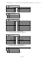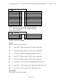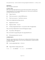
1
Mini4 Tritech/Trigger Daughterboard
(P/N 201600-xxx)
User’s Manual
And
Troubleshooting Guide
February 23, 2009
Revision C
Moog Components Group
Springfield Operations
750 West Sproul Road
Springfield, PA 19064
E-Mail: [email protected] URL: www.moog.com/components
Tel: 610-328-4000 Fax 610-605-6216
24/7 Technical Customer Support Hotline: 610-605-6101
Moog Components Group
201600-xxx Mini4 Tritech/Trigger Daughterboard Manual, Rev C
February 23, 2009
MANUAL REVISION HISTORY
REVISION
DATE
BY
NUMBER
REASON FOR
REVISION
A
7/27/06
LL
ORIGINAL
B
4/19/07
GSG
CORRECTIONS
IB
Updated contact information to reflect
C
02/23/09
Moog Components Group
TABLE OF CONTENTS
MINI4 TRITECH/TRIGGER DAUGHTERBOARD, P/N: 201600-XXX ................................. 3
1
1.1
1.2
1.3
1.4
1.5
1.6
1.7
1.8
TRITECH/TRIGGER INTERFACE: ....................................................................................................... 3
MINI4 TRITECH/TRIGGER DAUGHTERBOARD REVISION HISTORY:.................................................. 3
MINI4 TRITECH/TRIGGER DAUGHTERBOARD DASH (-) NUMBER DEFINITIONS ............................... 3
MINI4 TRITECH/TRIGGER DAUGHTERBOARD OPERATION:.............................................................. 3
TRITECH/TRIGGER INTERFACE DAUGHTERBOARD INDICATORS AND CONTROLS: ........................... 5
MINI4 TRITECH/TRIGGER DAUGHTERBOARD SPECIFICATIONS:..................................................... 11
MINI4 TRITECH/TRIGGER DAUGHTERBOARD POWER REQUIREMENTS:......................................... 11
MINI4 TRITECH/TRIGGER DAUGHTERBOARD DIMENSIONS: .......................................................... 11
Page 2 of 11
Moog Components Group
1
201600-xxx Mini4 Tritech/Trigger Daughterboard Manual, Rev C
February 23, 2009
Mini4 Tritech/Trigger Daughterboard, P/N: 201600-xxx
The Prizm Mini4 Tritech/Trigger daughterboard provides four channels of electricallyisolated digital Input or Output for use with most Acoustic Responder channels and a single
Tritech sonar channel. This board can be either a stand-alone daughterboard or stacked onto
a 201610 Mini4 RS-232 daughterboard. Refer to the 201610 Mini4 RS232 Daughterboard
manual for a description of this board and other daughterboards.
Each trigger channel is electrically isolated and independently powered. The board contains
jumper selections for Input/Output as well as Normal/Invert for both Input and Output
signals.
1.1 Tritech/Trigger Interface:
The Tritech/Trigger daughterboard also supports the Tritech SeaKing sonar. This specific
sonar uses the Arcnet protocol to carry its uplink and downlink data but operates only at the
lowest Arcnet data rate, 156Kbps. Other Tritech products can be connected to the same
network through this Arcnet board. A special interface hybrid board has be designed (with
Tritech's support) to directly interface to this line of sonar products. If the customer has
Tritech devices, these specific versions should be used to guarantee successful network
communications
1.2 Mini4 Tritech/Trigger Daughterboard Revision History:
The Mini4 Tritech/Trigger daughterboard has gone through the following printed circuit
board (PCB) and Assembly revisions:
PCB Revision A
PCB Revision B
Original design.
Various circuit and routing corrections.
1.3 Mini4 Tritech/Trigger Daughterboard Dash (-) Number
Definitions
The Mini4 Tritech/Trigger daughterboard has a Dash Number appended to the part
number. This Dash Number identifies the specific board configurations:
-001A
-001B
Original configuration, obsolete
Intended for use with TTL level (+5VDC) responders, provides for 5volt
levels on the output. Supports Tritech Sonars.
1.4 Mini4 Tritech/Trigger Daughterboard Operation:
Each trigger channel circuit has its own DC-DC converter and opto-couplers to provide
isolation of the I/O signals from the other channels and multiplexer system. Jumper posts
JP2 though JP9 handle the setup of the trigger/responder channels.
NOTE 1: The input trigger signals must always be positive relative to the input
signal’s ground pin. If the input signal goes more than 2 volts below the ground pin
Page 3 of 11
Moog Components Group
201600-xxx Mini4 Tritech/Trigger Daughterboard Manual, Rev C
February 23, 2009
then the input circuitry may be damaged. The input circuitry is the base of a
transistor current limited by a 15K ohm resistor.
NOTE 2: An input signal that is above approximately 2.5 Volts will be detected as a
“1” while a signal below about 0.8 Volts will be detected as a “0”.
NOTE 3: Any output signal will transition from approximately 0.0 Volts to +5 Volts
(if a 5VDC DC-DC supply is mounted on the board). Other output voltages can be
supported by changing the DC-DC converter.
For the following jumper settings discussion:
1. “normal” means the input or output signal is not inverted (i.e, +5VDC = +5VDC, 0
VDC = 0 VDC)
2. “inverted” means the input or output signal is inverted (i.e, , +5VDC = 0 VDC, 0
VDC = +5 VDC)
The input signal can be inverted or not-inverted as can be the output. Typically the board
would be configured for “normal” at both ends of the fiber link.
CHANNEL 1 JUMPER SETTINGS:
JP9 selects the polarity of the input trigger signal – either “normal” or “inverted”.
“Normal” means the input signal is not inverted
JP8 selects the polarity of the output signal – either “normal” or “inverted”.
CHANNEL 2 JUMPER SETTINGS:
JP7 selects the polarity of the input trigger signal – either “normal” or “inverted”.
“Normal” means the input signal is not inverted
JP6 selects the polarity of the output signal – either “normal” or “inverted”.
CHANNEL 3 JUMPER SETTINGS:
JP5 selects the polarity of the input trigger signal – either “normal” or “inverted”.
“Normal” means the input signal is not inverted
JP4 selects the polarity of the output signal – either “normal” or “inverted”.
CHANNEL 4 JUMPER SETTINGS:
JP3 selects the polarity of the input trigger signal – either “normal” or “inverted”.
“Normal” means the input signal is not inverted
JP2 selects the polarity of the output signal – either “normal” or “inverted”.
Page 4 of 11
Moog Components Group
201600-xxx Mini4 Tritech/Trigger Daughterboard Manual, Rev C
February 23, 2009
All of the four trigger channels run through a 16-pin AMP connector on the on the left edge
of the board. Refer to Section 1.5 for a pin-out of the connector.
For the Tritech section of the board to function, a Prizm Tritech hybrid board (P/N 970430001) must be fitted to the socket at U14. This hybrid board contains the Tritech isolation
transformers and associated circuitry. The Tritech sonar and processor are connected to the
green 2-pin Phoenix connector located at J7 (or optionally the SMB connector at J6). The
polarity of the signals must agree at both ends of the link (sonar head and the processor) for
the sonar to scan.
1.5 Tritech/Trigger Interface Daughterboard Indicators and
Controls:
The "TRITECH" LED (D15 on the bottom of the board under J7) will light green when
Tritech signals are being received into the board and will light red when signals are being
sent out of the board. This LED will be dimly lit most of the time but blink off periodically
when only one sonar is operating and connected to that Tritech board. Once one or more
sonar nodes are in operation at both ends of the network, the "TRITECH" LED will be
dimly lit continuously or blink off only rarely.
LEDS:
There are 3 surface mount vertical LED indicators on the top of the board and 14 surface
mount LED indicators (5 LEDs are right angle dual color) on the bottom of the board.
Top of Board
LED
Indication
D1 (Green)
Located at the upper left of the board serves as an indicator that +5VDC is available to the
board. Supply voltage to the board is selected via the placement of fuse F6 from the
Daughterboard Header (J1), F7 from the Diagnostics Header (J2), or F3 from the Auxiliary
daughterboard header (J4).
D2 (Green)
Located on the lower right edge of the board, labeled ‘TLINK’, if “ON” provides an
indication that the programmable logic device U10 is receiving a system clock and outputting
data onto the Daughterboard Header (J1).
D4 (Green)
Located on the lower right edge of the board, labeled ‘RLINK’, if “ON” provides an
indication that the programmable logic device U10 is receiving a system clock and receiveing
data from the Daughterboard Header (J1).
Bottom of Board
LED
Indication
D4 (Green)
Located at the upper left of the board serves as an indicator that the microprocessor is
receiving diagnostics requests from the diagnostics PC through the Diagnostics Header (J2)
or Diagnostics connector (J3). This LED will blink ON with a received request then OFF
with the next request.
Page 5 of 11
Moog Components Group
201600-xxx Mini4 Tritech/Trigger Daughterboard Manual, Rev C
February 23, 2009
D5 (Green)
Located at the upper center of the board serves as an indicator that the DC-DC converter U3
for Trigger channel 4 is working.
D6 (Green)
Labeled “TX DATE”, located at the upper left edge of the board serves as an indicator the
diagnostics data is being transmitted out of the board on the Diagnostics Header (J2) or
Diagnostics connector (J3).
D7 (Green)
Located at the upper center of the board serves as an indicator that the DC-DC converter U6
for Trigger channel 3 is working.
D8 (Green)
Labeled “RX DATE”, located at the upper left edge of the board serves as an indicator the
diagnostics data is being received into the board on the Diagnostics Header (J2) or
Diagnostics connector (J3).
D9
(Red/Green)
Located at the right center edge of the board serves as an indicator that Trigger data for
channel 4 is being sent out of the board (if red) or received into the board (if green).
D10
(Red/Green)
Located at the right center edge of the board serves as an indicator that Trigger data for
channel 3 is being sent out of the board (if red) or received into the board (if green).
D11
(Red/Green)
Located at the right center edge of the board serves as an indicator that Trigger data for
channel 2 is being sent out of the board (if red) or received into the board (if green).
D12 (Green)
Located at the middle center of the board serves as an indicator that the DC-DC converter U9
for Trigger channel 2 is working.
D13
(Red/Green)
Located at the right center edge of the board serves as an indicator that Trigger data for
channel 1 is being sent out of the board (if red) or received into the board (if green).
D14 (Green)
Located at the middle center of the board serves as an indicator that the DC-DC converter
U13 for Trigger channel 1 is working.
D15
(Red/Green)
Located at the right bottom edge of the board serves as an indicator that Tritech data is being
sent out of the board (if red) or received into the board (if green).
D16 (Green)
Located at the center bottom of the board serves as an indicator that power is being supplied
by the board to the Display LED header (J8).
D17 (Green)
Located at the center bottom of the board serves as an indicator that +3.3VDC is available on
the board, provided by U15.
CONNECTORS AND HEADERS:
J1
Daughterboard Header
VDC Supply
RXD_DB
GND
RXC_DB
RCV LINK
RXD_DB2
1
3
5
7
9
11
o
o
o
o
o
o
o
o
o
o
o
o
2
4
6
8
10
12
VDC Supply
TXD_DB
GND
TXC_DB
Future
TXD_DB2
Page 6 of 11
Moog Components Group
J2
Diagnostics Header
RT+
GND
GND
+5V
+5V
J3
o 1
o 2
o 3
J4
201600-xxx Mini4 Tritech/Trigger Daughterboard Manual, Rev C
1
3
5
7
9
o
o
o
o
o
o
o
o
o
o
2
4
6
8
10
RTGND
GND
+5V
+5V
Diagnostics Connector
RT+
GND
RT-
Auxiliary Daughterboard Header
+5V_ADB
RX17
RX18
RX19
RX20
RX21
RX22
GND
SYNC_IN
RT+
1
3
5
7
9
11
13
15
17
19
o
o
o
o
o
o
o
o
o
o
o
o
o
o
o
o
o
o
o
o
2
4
6
8
10
12
14
16
18
20
+5V_ADB
TX17
TX18
TX19
TX20
TX21
TX22
GND
FUT_ADB
RT-
NOTE: J4 header is located at the right side of the board.
Pin 1 is the upper left pin – as identified by a square pad.
J5
Trigger Connector
ISO_GND_D
T4 (OUT)
ISO_GND_C
T3 (OUT)
ISO_GND_B
T2(OUT)
ISO_GND_A
T1 (OUT)
16
14
12
10
8
6
4
2
o
o
o
o
o
o
o
o
o
o
o
o
o
o
o
o
16
13
11
9
7
5
3
1
ISO_GND_D
R4 (IN)
ISO_GND_C
R3 (IN)
ISO_GND_B
R2 (IN)
ISO_GND_A
R1 (IN)
NOTE: J5 connector is located at the left side of the board.
Pin 1 is the lower right pin – as identified by a square pad.
J6
Tritech SMB connector (OPTIONALLY PLACED)
J7
Tritech 2-pin Phoenix Connector
o 1
o 2
PHA
PHB
Page 7 of 11
February 23, 2009
Moog Components Group
J8
201600-xxx Mini4 Tritech/Trigger Daughterboard Manual, Rev C
Led Status Connector
GND
RLINK_LED
R_TRI_LED
R1_LED
R2_LED
R3_LED
R4_LED
FUTR1_LED
FUTR2_LED
FUTR3_LED
FUTR4_LED
NO CONNECT
1
3
5
7
9
11
13
15
17
19
21
23
o
o
o
o
o
o
o
o
o
o
o
o
o
o
o
o
o
o
o
o
o
o
o
o
2
4
6
8
10
12
14
16
18
20
22
24
PTC FUSE with +5VDC
TLINK_LED
T_TRI_LED
T1_LED
T2_LED
T3_LED
T4_LED
FUTT1_LED
FUTT2_LED
FUTT3_LED
FUTT4_LED
NO CONNECT
NOTE 1: J8 header is located at the bottom center side of the board.
Pin 1 is the upper right pin – as identified by a square pad.
NOTE : Signals are active low.
J12
ISP Header
+3.3V
TCK
N/C
GND
1
3
5
7
o
o
o
o
o
o
o
o
2
4
6
8
TMS
TDI
TDO
NOTE: J9 to be used only by PRIZM.
FUSES:
There are eight fuses for this board,
F1:
1.5 Amp PTC, Trigger channel 4 DC-DC power supply fuse
F2:
1.5 Amp PTC, Trigger channel 3 DC-DC power supply fuse
F3:
1.5 Amp PTC, Auxiliary Daughterboard header fuse at F3
F4:
1.5 Amp PTC, Trigger channel 2 DC-DC power supply fuse
F5:
1.5 Amp PTC, Trigger channel 1 DC-DC power supply fuse
F6:
1.5 Amp PTC, +5VDC input fuse for Daughterboard header at J1
F7:
1.5 Amp PTC, +5VDC input fuse for “DIAG HEADER” header at J2
F8:
1.5 Amp PTC, +5VDC output fuse for LED header at J12
SWITCHES:
There are no switches on this board.
Page 8 of 11
February 23, 2009
Moog Components Group
201600-xxx Mini4 Tritech/Trigger Daughterboard Manual, Rev C
February 23, 2009
TRIMPOTS:
There no trimpots on this board.
CONNECTORS:
There is one 16-pin right angle header on the left side of the board for connecting to the
Trigger/Responder devices, an optional SMB connector for Tritech and a 2-pin Phoenix
for normal connections to the Tritech.
J5:
Trigger Connector
J6:
Tritech sonar connector – optional SMB connector
J7:
Tritech sonar connector - 2-pin Phoenix connector
There are three daughterboard stacking connectors.
J1:
Daughterboard Connector
J2:
Diagnostics Header – not used
J3:
Auxiliary Daughterboard Header – for connection to RS-232 daughterboard
There is one 24-pin ribbon header for remote LED diagnostics display
J8:
24-pin ribbon, LED diagnostics
There is one header for programming the Lattice programmable device
J9:
ISP programming header, do not use
JUMPER POSTS:
The board contains jumper posts to allow the user to configure the board for input or output
of Trigger signals. Other jumpers are used for factory programming or testing and should
not be move or changed.
JP1:
Cypress programming header – do not use
JP2:
Trigger Channel 4 Output polarity select
3 o==o
o 1
for “NORMAL”
3o
o==o 1
Page 9 of 11
for “INVERTED”
Moog Components Group
JP3:
201600-xxx Mini4 Tritech/Trigger Daughterboard Manual, Rev C
Trigger Channel 4 Input polarity select
3 o
|
2 o
3 o
for “NORMAL”
1 o
JP4:
3 o==o
JP5:
o 1
for “NORMAL”
o 1
for “NORMAL”
3o
o==o 1
for “INVERTED”
2 o
|
1 o
for “INVERTED”
Trigger Channel 1 Output polarity select
o 1
for “NORMAL”
3o
o==o 1
for “INVERTED”
Trigger Channel 1 Input polarity select
3 o
|
2 o
3 o
for “NORMAL”
1 o
for “INVERTED”
3 o
1 o
JP9:
2 o
|
1 o
Trigger Channel 2 Input polarity select
for “NORMAL”
3 o==o
for “INVERTED”
Trigger Channel 2 Output polarity select
3 o
|
2 o
JP8:
o==o 1
3 o
1 o
JP7:
3o
Trigger Channel 3 Input polarity select
for “NORMAL”
3 o==o
for “INVERTED”
Trigger Channel 3 Output polarity select
3 o
|
2 o
JP6:
2 o
|
1 o
2 o
|
1 o
for “INVERTED”
Page 10 of 11
February 23, 2009
Moog Components Group
201600-xxx Mini4 Tritech/Trigger Daughterboard Manual, Rev C
February 23, 2009
1.6 Mini4 Tritech/Trigger Daughterboard Specifications:
Trigger Section:
Number of Channels:
Data rates supported:
Connector:
Trigger delay time:
Tritech Sonar Section:
Number of Channels:
Cable type supported:
Data rates supported:
4 bi-directional
DC to approximately 100KHz
16-pin AMP ribbon or crimp header
____ ms typically
one
Twisted pair with 2 pin Phoenix at J7
Coaxial with SMB (optionally at J6)
156Kbps ONLY
1.7 Mini4 Tritech/Trigger Daughterboard Power Requirements:
The Tritech/Trigger daughterboard uses approximately 500mA @ 5VDC.
1.8 Mini4 Tritech/Trigger Daughterboard Dimensions:
PC/104 format - 95.8 mm wide x 90.17 mm long x 13 mm thick
(3.775 in x 3.550 in x 0.50 in )
Page 11 of 11