1
81_GSBOOK.fm5 Page 277 Tuesday, October 14, 1997 4:04 PM
Appendix
A
MAX+PLUS II
Command-Line Mode
You can operate the MAX+PLUS II Compiler, Timing Analyzer, and
Simulator from the command prompt under UNIX, Microsoft Windows NT,
and Microsoft Windows 95.
Altera Corporation
277
81_GSBOOK.fm5 Page 278 Tuesday, October 14, 1997 4:04 PM
MAX+PLUS II Getting Started
To run MAX+PLUS II from a command prompt, type:
maxplus2 -h | -v | { <batch option(s)> [ <I/O option(s)> ] <project name> } 9
Multiple batch and I/O options can be used for a single project; multiple
projects can be processed with the same command line. The <project name>
indicates the end of the options for that project.
The <batch options> are as follows:
278
Batch Option:
Action:
-h or -help
displays information about command line
options
-v or -version
displays the MAX+PLUS II version number
-c or -compile
runs the Compiler
-ta_delay
runs the Timing Analyzer in Delay Matrix
mode
-ta_setup
runs the Timing Analyzer in Setup/Hold
Matrix mode
-ta_reg
runs the Timing Analyzer in Registered
Performance mode
-s or -simulate
runs the Simulator
-i or -ignore_errors
ignores errors from the Compiler, Simulator,
or Timing Analyzer, and continues processing
other projects specified in the same command
line, even if the processing on a previous
project has failed
Altera Corporation
81_GSBOOK.fm5 Page 279 Tuesday, October 14, 1997 4:04 PM
Appendix A: MAX+PLUS II Command-Line Mode
The <I/O options> are shown below. For each option, the <filename> defaults
to <project name> if you specify empty quotation marks ("").
I/O Option:
Action:
-tao "<filename>"
saves Timing Analyzer output in
<filename>.tao; if this option is not used,
<project name>.tao is generated automatically
-scf "<filename>"
uses <filename>.scf as the source of simulation
vectors; if this option is not used, the file
specified with the SIMULATION_INPUT_FILE
variable in <project name>.acf is used
automatically
-vec "<filename>"
uses <filename>.vec as the source of simulation
vectors
-cmd "<filename>"
uses <filename>.cmd file as the source of
simulation commands
-tbl "<filename>"
saves Simulator output in <filename>.tbl
-hst "<filename>"
records Simulator history in <filename>.hst
1
You can use > or >> to redirect MAX+PLUS II warning and error
messages to an ASCII file. (In UNIX, use >! and >>! instead of >
and >> if the noclobber variable is set.)
The following example compiles the upcntr project; compiles the chiptrip
project; runs a timing analysis on chiptrip in Registered Performance mode;
and simulates chiptrip using test.scf as the source of vectors:
maxplus2 -c upcntr -c -ta_reg -s -scf "test.scf" chiptrip 9
The following example compiles the chiptrip project, overwriting any
existing message.out file:
maxplus2 -c chiptrip > message.out 9
Altera Corporation
279
81_GSBOOK.fm5 Page 280 Tuesday, October 14, 1997 4:04 PM
MAX+PLUS II Getting Started
280
Altera Corporation
81_GSBOOK.fm5 Page 281 Tuesday, October 14, 1997 4:04 PM
Appendix
B
Altera Support
Services
AlteraÕs support team is dedicated to resolving your technical issues
quickly. Altera responds to your questions promptly and efficiently via
telephone, fax, or e-mail. Applications Engineers are located at Altera
headquarters in San Jose, California, and at locations around the world.
The Altera Applications, Literature, and Marketing Departments offer the
following services:
■
■
■
■
Altera Corporation
Product information
Technical support
Technical publications
Training courses
281
81_GSBOOK.fm5 Page 282 Tuesday, October 14, 1997 4:04 PM
MAX+PLUS II Getting Started
Contacting Altera Support Services
Table B-1 describes AlteraÕs support services.
Table B-1. Altera Support Services (Part 1 of 2)
Support Service
Product
Information
Contact Information Note (1)
Tel: (408) 544-7104
E-mail: [email protected]
WWW: http://www.altera.com
BBS: 544-6421 Note (2)
FTP site: [email protected]
Description
Up-to-date information on Altera
products is available from the Altera
Marketing Department between the
hours of 8:00 a.m. and 5:00 p.m. Pacific
Time, Monday through Friday.
or contact your local Altera
distributor or sales office
Technical Support U.S. & Canada Only:
Hotline: (800) 800-EPLD
or (408) 544-7000
Worldwide:
Tel: (408) 544-7000
Fax: (408) 544-6401
WWW: http://www.altera.com
BBS: 544-6421 Note (2)
FTP site: [email protected]
E-mail: [email protected]
Contact your local Altera
distributor or sales office for
design evaluations and on-site
support
Direct technical support on Altera devices
and software is available from the Altera
Applications Department between the
hours of 6:00 a.m. and 6:00 p.m. Pacific
Time, Monday through Friday.
Applications Engineers at Altera and Field
Applications Engineers located around the
world can evaluate customer designs,
recommend efficient design methods and
devices that will best meet your needs,
estimate device performance, demonstrate
MAX+PLUS II software, and provide onsite training.
The world-wide web (WWW) site provides
access to the Atlas technical support
database, and to product information and
technical publications.
You can use the FTP site and the BBS to
transfer files to and from the Altera
Applications Department for technical
support and review. The FTP site and the
BBS also provide software utilities and
technical publications.
Notes:
(1) AlteraÕs e-mail, world-wide web (WWW) site, bulletin board service (BBS), and File Transfer
Protocol (FTP) site are available 24 hours a day.
(2) The BBS requires a Bell Standard 212, CCITT standard, or compatible modem at up to
14,400 bps, using 8 data bits, 1 stop bit, and no parity.
282
Altera Corporation
81_GSBOOK.fm5 Page 283 Tuesday, October 14, 1997 4:04 PM
Appendix B: Altera Support Services
Table B-1. Altera Support Services (Part 2 of 2)
Support Service
Technical
Publications
Contact Information Note (1)
Tel: (888) 3-ALTERA
E-mail: [email protected]
WWW: http://www.altera.com
BBS: 544-6421 Note (2)
FTP site: [email protected]
Training Courses
Description
Altera produces a variety of technical
literature to help you select and design with
programmable logic, including application
notes and data sheets.
Altera also provides News & Views, a
quarterly newsletter that includes the latest
information on Altera products, technical
articles written by Altera Applications
Engineers, and a question and answer
section that addresses many commonly
asked questions. All registered users of
Altera products receive News & Views.
Altera provides a variety of training
courses to teach you innovative and
efficient design techniques. With these
or contact your local Altera sales courses, you can discover the time-saving
features of the MAX+PLUS II development
office
system, explore the design features of
AlteraÕs device families, or simply learn
about Altera products.
Altera Training Administrator:
Tel: 544-7000
Notes:
(1) AlteraÕs e-mail, world-wide web (WWW) site, bulletin board service (BBS), and File Transfer
Protocol (FTP) site are available 24 hours a day.
(2) The BBS requires a Bell Standard 212, CCITT standard, or compatible modem at up to
14,400 bps, using 8 data bits, 1 stop bit, and no parity.
f
Go to ÒContacting AlteraÓ in MAX+PLUS II Help for up-to-date information
on Altera contact information.
Altera Corporation
283
81_GSBOOK.fm5 Page 284 Tuesday, October 14, 1997 4:04 PM
MAX+PLUS II Getting Started
284
Altera Corporation
81_GSBOOK.fm5 Page 285 Tuesday, October 14, 1997 4:04 PM
Appendix
C
Additional
Workstation
Configuration
Information
This section describes how to change additional workstation configuration
items that control the appearance of MAX+PLUS II windows, serial port
configuration, screen height and width, printer ports, and fonts.
■
■
■
■
■
Altera Corporation
Customizing MAX+PLUS II Colors ..................................................... 286
Using the mwcolormanager Utility ..................................................... 288
Environment Variables .......................................................................... 288
Fonts.......................................................................................................... 292
Printers ..................................................................................................... 294
285
81_GSBOOK.fm5 Page 286 Tuesday, October 14, 1997 4:04 PM
MAX+PLUS II Getting Started
Customizing MAX+PLUS II Colors
You can customize the colors of various elements in the MAX+PLUS II
window by editing the ASCII-format win.ini file, which is copied into the
<userÕs home directory>/windows directory the first time you run
MAX+PLUS II.
The settings in this file determine the colors of basic window elements when
Windows Òlook and feelÓ is selected. For more information about changing
the Òlook and feelÓ of the user interface, go to ÒEnvironment VariablesÓ on
page 288. In contrast, the Color Palette command (Options menu) in
MAX+PLUS II determines the colors of specific objects displayed in
individual MAX+PLUS II application windows.
The [colors] section of win.ini defines the color of various elements in the
MAX+PLUS II window. Three values in the range of 0 to 255 define the
amount of red, green, and blue (RGB) that determine the color of each
element.
The following table shows the [colors] section of a sample win.ini file
and a brief description of each window element.
Component = R G B Value:
Description:
Desktop background
MAX+PLUS II workspace
MAX+PLUS II application
workspace
WindowText=0 0 0
Window text
Menu=255 255 255
Window background
MenuText=0 0 0
Menu text
ActiveTitle=0 0 128
Active window title bar
InactiveTitle=255 255 255
Inactive window title bar
TitleText=255 255 255
Title bar text in an active window
ActiveBorder=192 192 192
Active window border
InactiveBorder=192 192 192 Inactive window border
WindowFrame=0 0 0
Window frame
ScrollBar=192 192 192
Scroll bar background
ButtonFace=192 192 192
Button front surface
ButtonShadow=128 128 128
Shadow (i.e., darker edges) of an
unpressed button
Background=192 192 192
AppWorkspace=255 255 255
Window=255 255 255
286
Altera Corporation
81_GSBOOK.fm5 Page 287 Tuesday, October 14, 1997 4:04 PM
Appendix C: Additional Workstation Configuration Information
Component = R G B Value:
Description:
ButtonText=0 0 0
GrayText=128 128 128
Text on the face of a button
Text color when a menu command
is unavailable
Background behind highlighted
text
Highlighted text
Text in the title bar of an inactive
window
Lighter edges of an unpressed
button
Hilight=0 0 128
HilightText=255 255 255
InactiveTitleText=0 0 0
ButtonHilight=255 255 255
The following table shows the RGB values of the 16 standard colors
normally available on a color monitor. You can edit the colors in the
[colors] section of your win.ini file using these values to change the color
of the various window components. The availability of other colors depends
on the capabilities of your workstationÕs display system.
Color:
Red:
Green:
Blue:
White
Light Gray
Dark Gray
Black
Red
Dark Red
Green
Dark Green
Blue
Dark Blue
Yellow
Dark Yellow
Magenta
Dark Magenta
Cyan
Dark Cyan
255
192
128
0
255
128
0
0
0
0
255
128
255
128
0
0
255
192
128
0
0
0
255
128
0
0
255
128
0
0
255
128
255
192
128
0
0
0
0
0
255
128
0
0
255
128
255
128
Altera Corporation
287
81_GSBOOK.fm5 Page 288 Tuesday, October 14, 1997 4:04 PM
MAX+PLUS II Getting Started
1
If the appearance of colors in MAX+PLUS II is not satisfactory,
and editing the win.ini file does not help the problem, you should
select the Windows Òlook and feel,Ó either by setting the MWLOOK
environment variable described on page 290, or with the Change
Look system menu.
Using the mwcolormanager Utility
Altera provides the mwcolormanager utility to correct color flickering
problems that might occur when you change to MAX+PLUS II from another
application window. If another application changes the system colors after
you have started MAX+PLUS II, the colors of MAX+PLUS II window
elements may change when you return to MAX+PLUS II.
To correct color flickering problems when changing applications, insert the
following line as the first command in your .xinitrc file:
mwcolormanager [-display <display>][-extra <nn>]9
The -display <display> option allows you to specify a different display
than the default listed in the DISPLAY variable in your .cshrc (C shell users)
or .profile (Bourne or Korn shell users) file.
The -extra <nn> option allows you to specify a number nn of colors in
addition to the 20 colors that are allocated by default. Because MAX+PLUS II
only uses 16 colors, you should not use this option.
Environment Variables
MAX+PLUS II uses environment variables to configure various options and
locate its files. MAX+PLUS II initializes them when it is installed, but you
may wish to change them to optimize your system performance.
If you are using the C shell, environment variables are located in your .cshrc
file, and have the following format:
setenv <environment variable> <value>
288
Altera Corporation
81_GSBOOK.fm5 Page 289 Tuesday, October 14, 1997 4:04 PM
Appendix C: Additional Workstation Configuration Information
If you are using the Bourne or Korn Shell, environment variables are located
in your .profile file, and have the following format:
set <environment variable>=<value>
MAX2_HOME
The MAX2_HOME variable specifies the name of the MAX+PLUS II home
directory. The default is /usr/maxplus2. You should use this variable only if
the system displays an error message indicating that MAX+PLUS II files
cannot be found when you start the program.
MAX2_PLATFORM
The MAX2_PLATFORM variable specifies the name of the platform used to
run MAX+PLUS II. You should use this variable only if the following error
message is displayed when you start the program: Unable to determine the
type of system you are using.
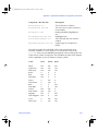
The following table lists the supported MAX+PLUS II platform names and
corresponding variable values:
Platform Name:
Variable Value:
SPARCstation running SunOS 4.1.3+
SPARCstation running Solaris 2.5+
HP 9000 Series 700/800
IBM RISC System/6000
sunos
solaris
hp
rs6000
MWCOM1, MWCOM2, MWCOM3 & MWCOM4
These variables control the mapping of serial ports in MAX+PLUS II, which
MAX+PLUS II accesses by the names COM1 through COM4, to the
corresponding UNIX serial tty ports. Table C-1 shows the default variable
values.
Altera Corporation
289
81_GSBOOK.fm5 Page 290 Tuesday, October 14, 1997 4:04 PM
MAX+PLUS II Getting Started
Table C-1. Serial Ports
Platform Name
MWCOM1
MWCOM2
MWCOM3
MWCOM4
IBM RISC System/6000
/dev/tty0
/dev/tty1
/dev/tty1
/dev/tty1
SPARCstation running SunOS 4.1.3
/dev/ttya
/dev/ttyb
/dev/ttyc
/dev/ttyd
SPARCstation running Solaris 2.5
dev/term/0
dev/term/1
dev/term/2
dev/term/3
HP 9000 Series 700/800
/dev/ttyd00
/dev/ttyd01
/dev/ttyd02
/dev/ttyd03
You can change the default mapping to reassign a COM port to one of the
UNIX serial ports. For example, MWCOM1=/dev/ttyc binds the ttyc serial
port to COM1, replacing the default port ttya.
MWFONT_CACHE_DIR
The MWFONT_CACHE_DIR variable specifies the name of the MAX+PLUS II
font cache directory. The default directory is /<userÕs home directory>/
windows.
MWLOOK
The MWLOOK variable controls the initial Òlook and feelÓ of the
MAX+PLUS II software on the workstation. MWLOOK may take the following
values:
Value:
Effect:
motif
windows
OSF/Motif look and feel
Microsoft Windows look and feel
The default value for MWLOOK is windows.
290
Altera Corporation
81_GSBOOK.fm5 Page 291 Tuesday, October 14, 1997 4:04 PM
Appendix C: Additional Workstation Configuration Information
MWRGB_DB
The MWRGB_DB variable specifies the full pathname to the file rgb.txt, which
maps color names to 24-bit RGB color values in the X server. If MWRGB_DB is
not used, the program looks for rgb.txt in the following directories, in order:
1.
2.
3.
4.
/usr/openwin/lib
/lib
/usr/X/lib
/usr/lib/X11
MWSCREEN_HEIGHT & MWSCREEN_WIDTH
The MWSCREEN_HEIGHT and MWSCREEN_WIDTH variables control the literal
size of objects on the screen. They can be set to the actual screen height and
width of your display, in millimeters. The default values are those of the X
server.
MWSYSTEM_FONT
The MWSYSTEM_FONT variable specifies the default system font used by
MAX+PLUS II. If this variable is not used, the default font is Helvetica. To
change the system font, set this variable to an existing X font name. For more
information, see ÒFontsÓ on page 292.
MWUNIX_SHARED_MEMORY
The MWUNIX_SHARED_MEMORY variable determines whether or not
MAX+PLUS II may use UNIX shared memory when it shares data with
another program.
If MWUNIX_SHARED_MEMORY is set to true, MAX+PLUS II can use UNIX
shared memory, which may improve its speed performance. If it is set to
false (the default value), MAX+PLUS II uses shared memory in the
X server when it shares data with another program. This shared memory
allows data exchanges between programs that run on different machines,
but which are displayed on the same X server.
Altera Corporation
291
81_GSBOOK.fm5 Page 292 Tuesday, October 14, 1997 4:04 PM
MAX+PLUS II Getting Started
MWWM
The MWWM variable determines which window manager is used on the
system. MWWM may take the following values:
Value:
Effect:
MWM
OLWM
TWM
uses Motif as the window manager
uses OpenLook as the window manager
uses the standard X window manager
MAX+PLUS II automatically detects whether you are using Motif or
OpenLook. This variable should be used only if you are using the standard
X window manager, TWM.
Fonts
MAX+PLUS II installs the fonts necessary for normal operation. By default,
these fonts are located in the /<userÕs home directory>/maxplus2/fonts
directory.
Adding New Fonts
You can add new X fonts to your system by performing the following steps:
v
Copy the fonts into the X11 font directory (/usr/lib/x11/fonts by
default) and restart the X server.
or:
292
1.
Copy the new fonts into the /usr/maxplus2/fonts directory.
2.
Make a font directory file (font.dir) by running the mkfontdir utility
(bldfamily utility on SunOS).
3.
Type xset +fp /usr/maxplus2/fonts 9 to prepend the font.dir
file to the front of the existing font path.
Altera Corporation
81_GSBOOK.fm5 Page 293 Tuesday, October 14, 1997 4:04 PM
Appendix C: Additional Workstation Configuration Information
4.
Type xset fp rehash 9 to reinitialize the font cache in the X server.
5.
Depending on your operating system, perform one of the following:
v
For Solaris, HP-UX, and AIX with Common Desktop
Environment (CDE) 1.0 (autostart enabled), go through the
following steps:
a.
Add the line DTSOURCEPROFILE=true to the .dtprofile
file in your home directory.
b.
Edit the .login file in your home directory to read as
follows (the following example is for C shell users):
if(!$?DT) then
<all text from your original .login file>
else
/usr/maxplus2/bin/mwcolormanager &
xset fp+ /usr/maxplus2/fonts
xset fp rehash
endif
or:
v
For SunOS and Solaris (without Common Desktop
Environment), add the following line to the .xinitrc Þle in your
home directory to add the directory to your font path each time
the X server is started:
xset fp+ /usr/maxplus2/fonts
A system default version of the .xinitrc file, called Xinitrc, is
available in the /usr/openwin/lib/ directory.
Altera Corporation
293
81_GSBOOK.fm5 Page 294 Tuesday, October 14, 1997 4:04 PM
MAX+PLUS II Getting Started
Font Aliases
The [FontSubstitutes] section of the win.ini file in the <userÕs home
directory>/windows directory provides aliases for font names. These aliases
are used to bind the MAX+PLUS II font names to the font names available
under the X server.
The following example shows the default font substitution list:
[FontSubstitutes]
Helv=helvetica
MS Sans Serif=ms sans serif
Tms Rmn=times
MS Serif=times
Times New Roman=times
Arial=helvetica
Printers
MAX+PLUS II uses its own Postscript printer driver to support Postscript
printers under UNIX.
Installing a New Printer
The following examples show how to edit the various sections of the win.ini
file to install a new printer.
[windows]
device=Apple LaserWriter II NT,PSCRIPT,LPT1
...
The device variable in the [windows] section defines the default
printer using the following syntax:
device=<output device name>,<device driver>,<port connection>
MAX+PLUS II uses the PSCRIPT keyword as the <device driver> to
specify the Postscript printer driver.
294
Altera Corporation
81_GSBOOK.fm5 Page 295 Tuesday, October 14, 1997 4:04 PM
Appendix C: Additional Workstation Configuration Information
[ports]
lpt1:=lp -c "%s"
lpt2:=lp -c -dps1700 "%s"
lpt3:=
...
The [ports] section lists the communication and printer ports
available to MAX+PLUS II. The Windows LPTn: variables are
equated to UNIX commands. In this example, LPT1 and LPT2 are
equated to the print command lp. MAX+PLUS II prints its output to
an intermediate Postscript file, which is then substituted for the term
“%s”. The term -dps1700 in the example refers to a UNIX printer
named ps1700 that should be defined in the UNIX printcap file.
[PrinterPorts]
Apple LaserWriter II NT=PSCRIPT,LPT1:,15,90
Postscript Printer QMS=PSCRIPT,LPT2:,15,90
The [PrinterPorts] section lists the active and inactive output
devices that can be accessed by the printer drivers, specifies the ports
to which the output devices are connected, and specifies time-out
values. In the example, the Apple LaserWriter II NT printer is
connected to the PSCRIPT queue, and is connected to LPT1.
MAX+PLUS II ignores the time-out values.
Printer Fonts
You can use the [PSFontSubstitutes] section of the win.ini file to
specify aliases for actual printer fonts to match the fonts in MAX+PLUS II.
The following example shows the default font substitute list:
[PSFontSubstitutes]
Helv=Helvetica
helvetica=Helvetica
MS Sans Serif=Helvetica
Tms Rmn=Times Roman
MS Serif=Times Roman
Times New Roman=Times Roman
Arial=Helvetica
courier=Courier
Altera Corporation
295
81_GSBOOK.fm5 Page 296 Tuesday, October 14, 1997 4:04 PM
MAX+PLUS II Getting Started
296
Altera Corporation
81_GSBOOK.fm5 Page 297 Tuesday, October 14, 1997 4:04 PM
Glossary
This glossary defines selected terms used in MAX+PLUS II documentation.
1 Choose Glossary (Help menu) to view the full MAX+PLUS II glossary on-line.
AHDL see Altera Hardware Description
Language.
ACF see Assignment & Configuration
File.
active-low node A node that is activated
when it is assigned a value of zero (0 in
AHDL and Verilog HDL or '0' in VHDL)
or GND (e.g., clrn, prn, oen). In AHDL
design files, an active-low node should be
assigned a default value of VCC with the
Defaults Statement.
ADF
see Altera Design File.
Altera Corporation
An ADF is also generated when a State
Machine File (.smf) is compiled.
Altera Hardware Description Language
(AHDL) A high-level, modular language
that is completely integrated into the
MAX+PLUS II system. You can create
AHDL Text Design Files (.tdf) with the
297
Glossary
Glossary
active-high node A node that is activated
when it is assigned a value of one (1 in
AHDL and Verilog HDL or '1' in VHDL)
or VCC (e.g., ena, clk).
Altera Design File (.adf) An ASCII-format
file (with the extension .adf) for Boolean
equation entry, used with AlteraÕs
A+PLUS software. ADFs use a netlist
format and Boolean equations to describe a
design. The MAX+PLUS II Compiler
automatically translates an ADF into a
Compiler Netlist File (.cnf) during project
compilation.
Glossary
A
Glossary
81_GSBOOK.fm5 Page 298 Tuesday, October 14, 1997 4:04 PM
MAX+PLUS II Getting Started
MAX+PLUS II Text Editor or any standard
text editor, then compile, simulate, and
program your projects within
MAX+PLUS II. AHDL supports Boolean
equation, state machine, conditional, and
decode logic. AHDL also allows you to
create and use parameterized functions,
and includes full support for functions in
the Library of Parameterized Modules
(LPM).
Text Design Export files (.tdx) and Text
Design Output Files (.tdo) generated by the
MAX+PLUS II Compiler are also written in
AHDL syntax.
Altera Megafunction Partner Program
(AMPP) A program that offers support to
third-party vendors to create and
distribute megafunctions for use with
MAX+PLUS II. You must enter a password
in the Megacore/AMPP Licenses dialog
box (accessed through the Authorization
Code command on the Options menu) to
enable a particular megafunction for
implementation in a design file.
Additionally, some vendors may provide
the option to view and edit a megafunction
design file.
For information on current AMPP vendors,
available megafunctions, and passwords,
contact Altera Marketing.
ancillary file A file that is associated with
a MAX+PLUS II project, but is not a design
file in the project hierarchy tree. Most
ancillary files also do not contain design
logic. User-editable ancillary files with the
same filename as the project appear in the
Hierarchy Display window. See the
following list:
298
Editable Ancillary Files:
Assignment & Configuration File (.acf)
Assignment & Configuration Output File
(.aco)
Command File (.cmd)
EDIF Command File (.edc)
Fit File (.fit)
FLEX Chain File (.fcf)
Hexadecimal (Intel-format) File (.hex)
History File (.hst)
Include File (.inc)
Jam File (.jam)
JTAG Chain File (.jcf)
Library Mapping File (.lmf)
Log File (.log)
Memory Initialization File (.mif)
Memory Initialization Output File (.mio)
Message Text File (.mtf)
Programmer Log File (.plf)
Report File (.rpt)
Serial Vector Format File (.svf)
Simulator Channel File (.scf)
Standard Delay Format (SDF) Output File
(.sdo)
Symbol File (.sym)
Table File (.tbl)
Tabular Text File (.ttf)
Text Design Export File (.tdx)
Text Design Output File (.tdo)
Timing Analyzer Output File (.tao)
Vector File (.vec)
VHDL Memory Model Output File (.vmo)
Non-Editable Ancillary Files:
Compiler Netlist File (.cnf)
Hierarchy Interconnect File (.hif)
JEDEC File (.jed)
Node Database File (.ndb)
Programmer Object File (.pof)
Raw Binary File (.rbf)
Serial Bitstream File (.sbf)
Simulator Initialization File (.sif)
Simulator Netlist File (.snf)
SRAM Object File (.sof)
Altera Corporation
81_GSBOOK.fm5 Page 299 Tuesday, October 14, 1997 4:04 PM
Glossary
area marquee In the Graphic or Symbol
Editors, the rectangular boundary
surrounding an area selection, which is
created by dragging Button 1 with the
Selection tool.
In the Hierarchy Display, the rectangular
border that is visible as you drag the mouse
to select an area. The marquee is visible
only while you are dragging the mouse.
area selection A defined rectangular
region that includes one or more adjacent
objects. In the Graphic and Symbol Editors,
this area is contained within a rectangular
border called an area marquee. In the
Waveform Editor, Floorplan Editor, and
Hierarchy Display, all objects within an
area selection are highlighted.
In the Graphic and Symbol Editors,
symbols, arcs, circles, diagonal lines, and
text blocks must lie completely within the
area marquee to be selected. When an
orthogonal line crosses the marquee, only
the portion within the marquee is selected.
assignment In AHDL and VHDL,
assignment refers to the transfer of a value
to a symbolic name or group, usually
through a Boolean equation. The value on
the right side of the equation is assigned to
the symbolic name or group on the left.
assignment (resource) see resource
assignment.
Assignment & Configuration File (.acf) An
ASCII file (with the extension .acf) that
stores information about probe, pin,
location, chip, clique, logic option, timing,
connected pin, local routing, and device
assignments, as well as configuration
settings for the Compiler, Simulator, and
Timing Analyzer for an entire project.
The ACF stores information entered with
menu commands in all MAX+PLUS II
applications, as well as pin, location, and
chip assignments entered in the Floorplan
Editor window. You can also edit an ACF
manually in a Text Editor window.
B
back-annotation The process of copying
device and resource assignments made by
the Compiler, which are stored in the Fit
File (.fit), into the Assignment &
Configuration File (.acf) for a project. The
back-annotation process preserves the
current fit in future compilations.
array see group.
ASCII American Standard Code for
Information Interchange. Text editing
software used for any MAX+PLUS II text
file, e.g., Text Design File (.tdf), Library
Altera Corporation
background process An application or
command that can run unattended as you
perform another task and which can
generate its own set of messages in a
Message Processor window. The following
299
Glossary
Glossary
Area selection is the process of selecting
multiple contiguous objects by dragging
Button 1 with the Selection tool. In the
Waveform Editor, such ÒobjectsÓ can
consist of adjacent nodes and groups,
whole waveforms, or intervals on one or
more waveforms. In the Floorplan Editor,
such ÒobjectsÓ can consist of adjacent pins,
nodes, logic cells, or assignment bins. In the
Hierarchy Display, file icons can be
selected.
Mapping File (.lmf), or Vector File (.vec),
must conform to this textual data coding
system.
81_GSBOOK.fm5 Page 300 Tuesday, October 14, 1997 4:04 PM
MAX+PLUS II Getting Started
MAX+PLUS II applications and commands
are background processes:
■
■
■
■
■
■
■
Compiler
Programmer
Simulator
Timing Analyzer
ACF Reader
Waveform Editor Import Vector File
command (File menu)
MAX+PLUS II Project Archive
command (File menu)
balloon text Pop-up text in the Floorplan
Editor that provides information on an
item under the mouse pointer, such as a
pin, I/O cell, logic cell, embedded cell, or
an assignment bin. Information is
displayed in the following formats:
<node name> @ <cell number>
<pin name> @ <pin number> (<pin function>
(<dedicated pin name>))
where the <pin name> or <cell name> is
replaced by the text <none> if no item is
assigned to a particular resource. If
multiple functions are assigned to the
resource, the first two names are listed,
followed by the text etc. if there are
additional names. In a last compilation
floorplan, the text (unrouted) appears
after the pin or node name for items that
did not fit successfully.
batch mode The simulation mode in
which Simulator commands are executed
from a Command File (.cmd) rather than
from on-screen options or menu
commands.
binary The base 2 number system (radix).
Binary digits are 0 and 1.
300
Boolean logic Logic that obeys the
theorems of Boolean algebra (George
Boole, ÒThe Laws of Thought,Ó 1854). The
Boolean portion of a design is the portion
which can be implemented in the AND-OR
matrix of a device.
branches The extensions of the hierarchy
tree that represent the different levels of the
hierarchy. A branch consists of a design
filename, a file icon, and any ancillary file
icons. The intersections of branches are
indicated by Ò+Ó and Ò-Ó branch buttons.
Connection arrows lead from higher-level
branches to lower-level branches.
breakpoint A user-defined set of
conditions that will interrupt simulation
when fulfilled.
buried node A combinatorial or registered
signal that does not drive an output pin.
buried register A register in an Altera
device that does not drive its output to a
pin. A buried register can be located on an
I/O pin or on a logic cell that has no output
to a pin. A buried register can be used to
implement internal logic.
bus A thick line in a Graphic Editor file
that represents multiple nodes. A bus
carries multiple signals between
components of a design, and can represent
from 2 to 256 nodes (i.e., bits).
In AHDL and Waveform Editor files, a
group is synonymous with a bus.
In VHDL, a bus is a guarded signal that
may have its drivers, i.e., signal sources,
turned off. In VHDL, a bus is called an
array, and is not limited to 256 symbolic
names. An example of an array type is
STD_LOGIC_VECTOR. See Section 3.2.1:
Altera Corporation
81_GSBOOK.fm5 Page 301 Tuesday, October 14, 1997 4:04 PM
Glossary
Array Types in the IEEE Standard VHDL
Language Reference Manual for more
information. Only one- and twodimensional arrays of scalar elements are
supported.
In Verilog HDL, a bus is an array of nets,
and is limited to 256 symbolic names. See
section 3.3: Vectors in the IEEE Standard
Hardware Description Language Based on
the Verilog Hardware Description
Language manual for more information.
bus (or group) name The name of a bus (or
group) of up to 256 nodes.
Example: bus a[4..1] consists of the
nodes a4, a3, a2, and a1.
Example: bus b[2..1][1..0] consists of
the nodes b2_1, b2_0, b1_1, and b1_0.
A sequential name, consisting of a commaseparated list of names, can be entered in
AHDL Text Design Files (.tdf) and Graphic
Design Files (.gdf). In TDFs only, this list of
names must be enclosed in parentheses.
Sequential bus names can include singleand dual-range bus names.
An arbitrary bus name, consisting of up to
32 name characters, can be entered in a
Waveform Design File (.wdf), Simulator
Channel File (.scf), or Vector File (.vec). An
arbitrary bus name does not indicate how
many members are included in the bus.
bus pinstub The location on the boundary
of a mega- or macrofunction symbol,
represented by an ÒxÓ in the Symbol File
(.sym), that represents multiple inputs or
outputs to the function. A bus (thick line)
drawn in a Graphic Editor file must
connect to a bus pinstub with the same
number of bits to be recognized as a
connection to the function.
Glossary
ByteBlaster A Parallel download cable
that allows PC users to program and
configure devices in-system. The
ByteBlaster provides programming
support for MAX 7000S and MAX 9000
devices, and configuration support for
FLEX 6000, FLEX 8000, and FLEX 10K
devices. Multi-device JTAG chain
programming and configuration are also
available for FLEX 10K, MAX 7000S, and
MAX 9000 devices. Multi-device FLEX
chain configuration is available for
FLEX 6000, FLEX 8000, and FLEX 10K
devices.
The ByteBlaster is connected to a parallel
printer port on a PC via a fully populated
DB25-to-DB25 cable. The ByteBlasterÕs
10-pin female plug connects to a 10-pin
male header on the circuit.
Example: a[3..0],dout[6..4],z3
The first name in the series of names in a
single-range, dual-range, or sequential
name is the most significant bit (MSB) of
Altera Corporation
301
Glossary
A single-range or dual-range name consists
of up to 32 name characters, followed by
one or two ranges of numbers or arithmetic
expressions in brackets. (Dual-range
names are not supported in Waveform
Editor files.) The start and end of the
number range are separated by two
periods. Each number in the sequence
represents an individual node (or bit).
the bus; the last name is the least significant
bit (LSB).
81_GSBOOK.fm5 Page 302 Tuesday, October 14, 1997 4:04 PM
MAX+PLUS II Getting Started
C
chip A group of logic functions defined as
a single, named unit. A chip is assigned to
an actual device by either the user or the
Compiler.
You can make chip assignments on logic
functions in design files. Items that are
assigned to the same chip are placed in the
same device during compilation. The term
device always refers to an actual
programmable logic device, whereas the
term chip always refers to a group of logic
functions.
When the Compiler processes a project,
each chip name is assigned to a
corresponding programming file for a
particular device.
Classic An Altera device family based on
AlteraÕs original EPROM-based EPLD
architecture. MAX+PLUS II provides
support for the following Classic devices:
EP600I, EP610, EP610I, EP900I, EP910,
EP910I, EP1800I, and EP1810 devices.
Clear An input signal that resets a
register. A synchronous Clear signal resets
on each rising or falling Clock edge. An
asynchronous Clear signal resets
regardless of the Clock signal.
clique A group of logic functions defined
as a single, named unit. The Compiler
attempts to keep clique members together
when it fits the project. A clique
assignment allows you to group all logic on
a speed-critical path, thus improving
performance.
If possible, all clique members are assigned
to the same LAB. If the clique members will
not fit into a single LAB, they are placed in
302
the same row (in FLEX 10K, FLEX 8000,
FLEX 6000, and MAX 9000 devices only) or
the same device.
Clock A signal that triggers registers.
In a flipflop or state machine, the Clock is
an edge-sensitive signal. The output of the
flipflop can change only on the Clock edge.
For example, in a D flipflop, the input
value is stored and placed on the output at
the Clock edge.
In some cases, MAX+PLUS II lists the Latch
Enable input to a latch as a Clock, e.g., in a
Delay Matrix timing analysis.
Clock Enable The level-sensitive signal on
an enabled flipflop, i.e., a flipflop with an
ÒEÓ suffix, including DFFE, TFFE, SRFFE,
and JKFFE. When the Clock Enable is low,
Clock transitions on the Clock input to the
flipflop are ignored.
column A vertical line of LABs connected
by a column FastTrack Interconnect path in
a FLEX 10K, FLEX 8000, FLEX 6000, or
MAX 9000 device.
COM or RS-232 port An RS-232 serial
communication port on a PC or UNIX
workstation. The BitBlaster, which is used
to configure and program devices insystem, must connect to a COM port.
combinatorial feedback Feedback from a
logic cell that goes back into the deviceÕs
logic array. It is the direct function of the
inputs to a logic cell, and does not retain
values from earlier inputs.
combinatorial output Output from a logic
cell that is a direct function of the inputs,
without regard to the Clock; i.e., it does not
retain values resulting from earlier inputs.
Altera Corporation
81_GSBOOK.fm5 Page 303 Tuesday, October 14, 1997 4:04 PM
Glossary
Command File (.cmd) An ASCII text file
(with the extension .cmd) that contains
commands for batch-mode simulation.
comment In the Graphic and Symbol
Editors, a comment is a free-floating block
of text used to document the design. It is
not associated with any object. A comment
stands alone anywhere within Graphic
Editor files. A comment also stands alone
within the symbol border of a Symbol
Editor file. Comments are ignored by the
Compiler, and can be used to document
various sections of a file.
In all MAX+PLUS II text files except VHDL
Design Files (.vhd), Verilog Design
Files (.v), and Assignment &
Configuration Files (.acf), e.g., in Report
Files (.rpt), Vector Files (.vec), and Text
Design Files (.tdf), a comment is any string
of characters enclosed in percent symbols
(%). You can insert comments wherever
white space is allowed in text files.
In VHDL Design Files and ACFs,
comments begin with two dashes (--) and
continue to the End-of-Line. AHDL TDFs
also support VHDL-style comments. If you
use a VHDL-style comment in a TDF, you
must separate the two dashes from any
Altera Corporation
In Verilog Design Files, comments begin
with two slashes (//) and continue to the
End-of-Line. Verilog Design Files and
ACFs also support comments consisting of
any string of characters enclosed between
/* and */ characters.
Compiler Netlist File (.cnf) A binary file
(with the extension .cnf) that contains the
data from a design file. The CNF is created
by the Compiler Netlist Extractor module
of the MAX+PLUS II Compiler.
Configuration EPROM AlteraÕs family of
serial EPROMs, which are designed to
configure FLEX 6000, FLEX 8000, and
FLEX 10K devices. This device family
includes the EPC1, EPC1213, EPC1064,
EPC1064V, and EPC1441 devices.
connection dot A dot entered at an
intersection of two signal lines (nodes or
buses) in a Graphic Editor file. The
connection dot indicates that the signals
are logically connected.
construct A unit in a text design language
such as AHDL, VHDL, Verilog HDL, or
EDIF.
continuity checking A test for open circuits
between device pins and programming
adapter sockets. This test verifies that a
device is properly seated in the socket of
the adapter.
cutoff node A node that is excluded from
timing analysis. The signal associated with
a node can be cut off from a timing analysis
by tagging it with the Timing Analysis
Cutoff command.
303
Glossary
Glossary
In the Waveform Editor, a comment is a
line of text used to annotate the waveforms
in the waveform drawing area . It is not
associated with any waveform. A comment
is anchored to the time on the time scale
where the first character is entered. A label
appears in the Name field to indicate a
comment line; when a comment is added
between two existing nodes, it appears in a
blank space, which is inserted between the
waveforms. Comments are ignored by the
Compiler.
preceding symbolic name with at least one
space.
81_GSBOOK.fm5 Page 304 Tuesday, October 14, 1997 4:04 PM
MAX+PLUS II Getting Started
D
database A flattened representation of all
design files in a MAX+PLUS II project
hierarchy. The database is used internally
by Compiler modules during compilation.
decimal The base 10 number system
(radix). Decimal digits are 0 through 9.
In AHDL,VHDL, and Verilog HDL no
special notation is needed to indicate
decimal digits.
default Simulator Channel File (.scf) A
Simulator Channel File (.scf) that can
contain all nodes and groups that are in the
Simulator Netlist File (.snf) for a project. It
is created automatically with the Enter
Nodes from SNF command (Node menu)
in the Waveform Editor.
default timing tagging The Timing
Analyzer provides the following default
node tagging for timing analysis:
Analysis Mode: Default Tagging:
Delay Matrix
Setup/Hold
Matrix
Registered
Performance
304
All input pins are
sources; all output pins
are destinations.
All input pins are
sources; all data and
Clock inputs to
registers, Latch Enable
inputs to latches, and
data, address, and Write
Enable inputs to
asynchronous RAM are
destinations.
All Q outputs of
registers are sources; all
data and Clock Enable
inputs to registers are
destinations.
delimiter A text string, character, or
keyword used to define the beginning or
the end of a statement or construct in a text
file.
For example, [ and ] are delimiters of
AHDL group ranges and % is a comment
delimiter in many MAX+PLUS II text files.
design file A file that contains logic for a
MAX+PLUS II project and is compiled by
the Compiler. The following files are
design files:
■
■
■
■
■
■
■
■
■
■
Altera Design File (.adf)
EDIF Input File (.edf) *
Graphic Design File (.gdf) *
OrCAD Schematic File (.sch) *
State Machine File (.smf)
Text Design File (.tdf) *
Verilog Design File (.v)
VHDL Design File (.vhd) *
Waveform Design File (.wdf)
Xilinx Netlist Format File (.xnf)
An asterisk (*) indicates the design files
that can exist as top-level files in
hierarchical projects. Other design files
must be the only design file in a project or
must exist at the bottom level of a
hierarchical project.
destination node A node that is tagged
(designated) as the destination of a signal
for the purpose of timing analysis. A
destination node is tagged with the Timing
Analysis Destination command (Utilities
menu), and can be any node that is the
input to a logic function or a pin.
device A device refers to an Altera
programmable logic device, including
Classic, MAX 5000, MAX 7000, MAX 9000,
Altera Corporation
81_GSBOOK.fm5 Page 305 Tuesday, October 14, 1997 4:04 PM
Glossary
FLEX 6000, FLEX 8000, and FLEX 10K
device families.
Altera also offers Configuration EPROM
devices which are used to configure
FLEX 6000, FLEX 8000, and FLEX 10K
devices.
device assignment A device assignment
assigns a user-specified block of logic
functions, called a chip, to a specific Altera
device.
Option:
Device Family:
Enable LOCK
Output
JTAG User Code
Low-Voltage I/O
Release Clears
Before Tri-States
FLEX 10K
Security Bit
Turbo Bit
device option An option that controls a
device. Altera devices offer the following
device options:
Use Low-Voltage
Configuration
EPROM
User Code
Option:
Device Family:
Auto-Restart
Configuration on
Frame Error
Disable Start-Up
Time-Out
Enable Chip-Wide
Output Enable
Enable Chip-Wide
Reset
Enable DCLK
Output in User
Mode
Enable INIT_DONE
Output
Enable JTAG
Support
FLEX 6000,
FLEX 8000, and
FLEX 10K
FLEX 8000
Altera Corporation
FLEX 6000 and
FLEX 10K
FLEX 6000 and
FLEX 10K
FLEX 8000
FLEX 6000 and
FLEX 10K
MAX 7000S,
FLEX 6000, and
FLEX 8000
User-Supplied
Start-Up Clock
Glossary
Glossary
device family A group of Altera
programmable logic devices with the same
fundamental architecture. Altera families
include the Classic, MAX 5000, MAX 7000,
MAX 9000, FLEX 6000, FLEX 8000,
and FLEX 10K, device families.
FLEX 10K
All
FLEX 6000,
FLEX 8000, and
FLEX 10K
Classic, MAX 5000,
MAX 7000, and
MAX 9000
Classic, MAX 5000,
MAX 7000, and
MAX 9000 (Logic Cell
Turbo Bit can be
applied to all logic
cells in a MAX 7000
or MAX 9000 device.)
FLEX 6000 and
FLEX 10K
MAX 7000S and
MAX 9000
FLEX 6000,
FLEX 8000, and
FLEX 10K
dual I/O feedback A combination of pin
feedback and register or combinatorial
feedback on the same logic cell.
dynamic models Models that represent
actual combinatorial logic in timing
Simulator Netlist Files (.snf).
Dynamic models are generated for the
logic in a timing SNF when the CompilerÕs
Optimize Timing SNF command
(Processing menu) is turned on. Instead of
processing the combinatorial logic, the
Simulator or Timing Analyzer refers to the
representative dynamic model.
305
81_GSBOOK.fm5 Page 306 Tuesday, October 14, 1997 4:04 PM
MAX+PLUS II Getting Started
Dynamic models allow a simulation to run
faster; however, the Compiler requires
additional time to generate the SNF.
E
EAB
EC
see Embedded Array Block.
see embedded cell.
EDIF Electronic Design Interchange
Format. An industry-standard format for
the transmission of design data.
You can generate an EDIF 2 0 0 or 3 0 0
netlist file from a schematic design or from
a VHDL or Verilog HDL design that has
been processed with an appropriate
industry-standard synthesis tool and then
import the file into MAX+PLUS II as an
EDIF Input File (.edf). MAX+PLUS II
supports EDIF Input Files that contain
functions from the Library of
Parameterized Modules (LPM). The
MAX+PLUS II Compiler can also generate
one or more EDIF Output Files (.edo) in
either EDIF 2 0 0 or 3 0 0 format that contain
functional or timing information for
simulation with a standard EDIF
simulator.
The MAX+PLUS II CompilerÕs EDIF
Netlist Reader and EDIF Netlist Writer
modules have been awarded the Electronic
Industries AssociationÕs (EIA) EDIF
version 3 0 0 Self-Verification Seal of
Approval. This award indicates that
MAX+PLUS II EDIF 3 0 0 support has
successfully completed the testing process
to ensure compliance with the EDIF 3 0 0
Netlist View standard.
EDIF Command File (.edc) An ASCII text
file (with the extension .edc) used to
customize the format of EDIF Output Files
306
(.edo) created by the CompilerÕs EDIF
Netlist Writer module.
EDIF Input File (.edf) An EDIF version 2 0 0
or 3 0 0 netlist file generated by any
standard EDIF netlist writer. EDIF Input
Files (with the extension .edf) can be
compiled by the MAX+PLUS II Compiler.
MAX+PLUS II supports EDIF Input Files
that contain functions from the Library of
Parameterized Modules (LPM).
EDIF Output File (.edo) An EDIF version
2 0 0 or 3 0 0 netlist file (with the extension
.edo) generated by the EDIF Netlist Writer
module of the Compiler. This file can be
exported to an industry-standard UNIX
workstation or PC environment for
simulation.
EEPROM Electrically Erasable
Programmable Read-Only Memory. A
form of reprogrammable semiconductor
memory in which the contents (program)
can be erased by subjecting the device to
appropriate electrical signals.
Embedded Array Block (EAB) A physically
grouped set of 8 embedded cells that
implement memory (RAM or ROM) or
combinatorial logic in a FLEX 10K device.
An EAB consists of an embedded cell array,
with data, address, and control signal
inputs and data outputs that are optionally
registered.
A single EAB can implement a memory
block of 256 × 8, 512 × 4, 1,024 × 2, or
2,048 × 1 bits. Each embedded cell within
the EAB implements up to 256 bits of
memory. For memory blocks of these sizes,
an EAB has 8, 4, 2, or 1 outputs,
respectively. Multiple EABs can be
combined to create larger memory blocks.
Altera Corporation
81_GSBOOK.fm5 Page 307 Tuesday, October 14, 1997 4:04 PM
Glossary
The EAB is fed by row interconnect paths
and a dedicated input bus.
embedded cell (EC)
A memory element
that exists in the embedded array of a
FLEX 10K device, and which can
implement memory (RAM or ROM) or
combinatorial logic. An Embedded Array
Block (EAB) consists of a group of 8
embedded cells that can implement a
memory block of 256 × 8, 512 × 4, 1,024 × 2,
or 2,048 × 1 bits. Each embedded cell within
an EAB implements up to 256 bits of
memory. Depending on the depth of the
memory, up to 8 of the embedded cells in
an EAB have outputs. For memory blocks
of 256 × 8, 512 × 4, 1,024 × 2, or 2,048 × 1 bits,
an EAB has 8, 4, 2, or 1 outputs,
respectively.
DEFINE MAX(a,b) = (a > b) ? a : b;
expander product term A single product
term with an inverted output that feeds
back into the Logic Array Block (LAB) of a
MAX 5000, MAX 7000, or MAX 9000
device.
An uncommitted expander product term
that can be shared with other logic cells in
the same LAB is called a shareable
expander; a product term that has been
shared in this manner is called a shared
expander.
In MAX 7000 and MAX 9000 devices only,
an expander product term that is
ÒborrowedÓ from an adjacent logic cell in
the same LAB is called a parallel expander.
extension see filename extension.
EPLD Erasable Programmable Logic
Device, i.e., an Altera device that is a
member of the Classic, MAX 5000,
MAX 7000, or MAX 9000 device families.
EPROM Erasable Programmable ReadOnly Memory. A form of reprogrammable
semiconductor memory in which the
contents (program) can be erased by
subjecting the device to ultraviolet light of
the proper wavelength.
evaluated function An mathematical
function that evaluates an arithmetic
expression and returns a value based on
one or more arguments. The AHDL Define
Statement can be used to create evaluated
Altera Corporation
F
family-specific mega- or macrofunction An
Altera-provided mega- or macrofunction
that contains logic optimized for the
architecture of a specific device family.
The functionality of a family-specific megaor macrofunction is always the same,
regardless of the device family for which it
is designed. However, the actual
primitives and nodes used within the
mega- or macrofunction file can vary from
family to family to take advantage of
different device architectures, thus
providing higher performance and/or
more efficient implementation.
307
Glossary
Glossary
Embedded cells have ÒnumbersÓ of the
format EC<number>_<row letter>, where
<number> ranges from 1 to 8 and <row
letter> consists of the row letter of the EAB.
functions. The following example shows
the definition of the evaluated function
MAX:
81_GSBOOK.fm5 Page 308 Tuesday, October 14, 1997 4:04 PM
MAX+PLUS II Getting Started
fan-in and fan-out Fan-in refers to input
signals that feed the input equations of a
logic cell.
Fan-out refers to output signals that are fed
by the output equations of a logic cell.
FastTrack Interconnect Dedicated
connection paths that span the entire width
and height of a FLEX 6000, FLEX 8000,
MAX 9000, or FLEX 10K device. These
connection paths allow signals to travel
between all Logic Array Blocks (LABs) in a
device.
FCF see FLEX Chain File.
file icon An icon that appears in a
MAX+PLUS II application window and
represents a file in the current hierarchy
tree. Double-clicking Button 1 on an icon
opens the file that it represents.
In the Hierarchy Display, the file icon
shows which MAX+PLUS II editor can
open the file. The filename extension is
displayed at the bottom of the file icon to
show the file type; the filename is
displayed to the left of the file icon.
In the Compiler, the file icons show input
and output files for the current project.
filename The name of a design file,
ancillary file, or other file, without the
extension.
A single filename can contain up to 32
name characters, plus a 3-character
filename extension. A full pathname plus
filename and extension can contain up to
128 characters.
Because Windows 3.1 and Windows for
Workgroups 3.11 support only 8-character
308
filenames, MAX+PLUS II maps longer
filenames on all Windows operating
systems to 8-character filenames by
default. These filename mappings are
stored in the maxplus2.idx file in each
directory that contains long filenames.
However, you can override this behavior
and us the built-in support for long
filenames available in Windows NT and
Windows 95 by setting the
USE_WINNT_LONG_FILENAMES variable
in the [system] section of your
maxplus2.ini file to ON.
In the Hierarchy Display window, a
filename, along with the file icon and
filename extension, represents a file in the
current hierarchy tree.
filename extension The one, two, or threeletter extension of a filename that follows a
period (.).
In the Hierarchy Display window, a
filename extension, along with the
filename and the file icon, represents a file
in the current hierarchy or the current
project.
Fit File (.fit) An ASCII file (with the
extension .fit) generated by the Compiler
that documents pin, logic cell, I/O cell,
embedded cell, chip, and device
assignments made during the last
compilation. Assignments are recorded in
Assignment & Configuration File (.acf)
syntax.
The Fit File can be used for back-annotation
and for functional testing in the Simulator
and Programmer. To preserve assignments
permanently, Fit File assignments can be
back-annotated into a projectÕs ACF with
the Back-Annotate Project command
(Assign menu).
Altera Corporation
81_GSBOOK.fm5 Page 309 Tuesday, October 14, 1997 4:04 PM
Glossary
You can also display a read-only version of
Fit File information from the most recent
project compilation in the Floorplan Editor.
FLEX Chain File (.fcf) An ASCII file (with
the extension .fcf) that stores programming
file names for use in configuring multiple
FLEX 6000, FLEX 8000, or FLEX 10K
devices in a Passive Serial configuration
scheme. An FCF saves the information
entered with the ProgrammerÕs MultiDevice FLEX Chain Setup command
(FLEX menu).
FLEX 6000 An Altera device family based
on Flexible Logic Element MatriX
architecture. This SRAM-based family
offers high-performance, registerintensive, high-gate-count devices. The
FLEX 6000 device family includes the
EPF6016 device.
FLEX 10K devices, which include
EPF10K50V, EPF10K130V, and
EPF10K250A devices, are enhanced
versions of FLEX 10K devices, and are
function-, pin-, and programming-filecompatible with FLEX 10K devices.
FLEX 10KA devices differ from FLEX 10K
devices in that they are 3.3-V versions of
FLEX 10K devices.
The EPF10K100GC503-3DX device
includes built-in ClockLock and
ClockBoost phase-locked loop circuitry.
flipflop or register An edge-triggered,
clocked storage unit that stores a single bit
of data. A low-to-high transition on the
Clock signal changes the output of the
flipflop, based on the value of the data
input(s). This value is maintained until the
next low-to-high transition of the Clock, or
until the flipflop is preset or cleared.
Depending on the architecture of the
device family, a register can be
programmed as a level-sensitive flowthrough latch or as an edge-triggered D,T,
JK, or SR flipflop.
1 Altera recommends using
FLEX 8000A devices rather than
FLEX 8000 devices for all new
designs.
In Verilog HDL, ÒregisterÓ is also used to
describe the abstraction of a data storage
device that the MAX+PLUS II Compiler
uses to infer registers.
FLEX 10K An Altera device family based
on Flexible Logic Element MatriX
architecture. This SRAM-based family
offers high-performance, registerintensive, high-gate-count devices with
embedded arrays. The FLEX 10K device
family includes the EPF10K100, EPF10K70,
fMAX (maximum Clock frequency) The
maximum Clock frequency that can be
achieved without violating internal setup
and hold time requirements.
Altera Corporation
fMAX is also a timing assignment that
specifies the minimum acceptable Clock
frequency. In MAX+PLUS II, you can
309
Glossary
Glossary
FLEX 8000 An Altera device family based
on Flexible Logic Element MatriX
architecture. This SRAM-based family
offers high-performance, registerintensive, high-gate-count devices. The
FLEX 8000 device family includes the
EPF8282V, EPF8282A, EPF8282AV,
EPF8452A, EPF8636A, EPF8820A,
EPF81188A, and EPF81500A devices.
EPF10K50, EPF10K40, EPF10K30,
EPF10K20, and EPF10K10 devices.
81_GSBOOK.fm5 Page 310 Tuesday, October 14, 1997 4:04 PM
MAX+PLUS II Getting Started
specify a required fMAX for an entire
project and/or for any input pin (INPUT or
INPUTC), bidirectional pin (BIDIR or
BIDIRC input function), or a register.
Function Prototype Specifies the ports
(pinstubs) of a primitive, megafunction, or
macrofunction in AHDL. A Function
Prototype consists of the name of the
function, and a list of its inputs and
outputs. For mega- and macrofunctions,
the Function Prototype can also contain
parameters that are used to specify the
characteristics of the function. Function
Prototypes are specified in the Function
Prototype Statement. They are often stored
in Include Files (.inc). Include Files that
contain Function Prototypes for Alteraprovided mega- and macrofunctions are
located in the \maxplus2\max2lib\
mega_lpm and \maxplus2\max2inc
directories created during installation,
respectively. (On a UNIX workstation, the
maxplus2 directory is a subdirectory of the
/usr directory.)
To implement an instance of a mega- or
macrofunction in AHDL, its logic must be
defined in a design file and its Function
Prototype must be declared. (Function
Prototypes are optional for primitives.)
You can then create an instance of the
function with an Instance Declaration or an
in-line reference.
1 When you use a Module
Instantiation in Verilog HDL, the
MAX+PLUS II Compiler uses the
port name and ordering information
in AHDL Include Files that contain
Function Prototypes to implement
an instance of the logic function.
310
G
GDF
see Graphic Design File.
glitch or spike A signal value pulse that
occurs when a logic level changes two or
more times over a short period.
When the Simulator is in timing or linked
simulation mode, you can define the length
of a glitch and monitor the project for
pulses shorter than the defined value.
Glitch detection is not available in
functional simulation mode.
global signal A pin- or logic-driven signal
that passes through the global routing on a
device before performing its specified
function. Clock, Preset, Clear, and Output
Enable signals can be global signals.
1 Logic-driven global signals are
available only in FLEX 6000 devices.
A global signal can be set in various ways:
■
During design entry with a GLOBAL
primitive. You can use a dedicated
input pin to drive a global signal
directly by feeding its output directly
to a GLOBAL primitive. You can also
use the output of a logic function as a
global signal by feeding its output
directly to a GLOBAL primitive. A logicdriven global signal consumes a
dedicated global input pin.
■
With the Automatic Global option in the
Global Project Logic Synthesis dialog
box (Assign menu). The Compiler
chooses the pin-driven signal that
feeds the most flipflops as a global
Clock, Preset, or Clear, and the signal
that feeds the most TRI buffers is
chosen as the global Output Enable.
Altera Corporation
81_GSBOOK.fm5 Page 311 Tuesday, October 14, 1997 4:04 PM
Glossary
■
With the Global Signal logic option in
the Individual Logic Options dialog
box, which you can open from the
Logic Options dialog box (Assign
menu). When this option is turned on
for an input pin or for a single-output
logic function, it is equivalent to using
a GLOBAL primitive. Turning this logic
option off prevents an input pin from
being used as a global signal.
GND A low-level input voltage.
Graphic Design File (.gdf) A schematic
design file (with the extension .gdf) created
with the MAX+PLUS II Graphic Editor.
An OrCAD Schematic File (.sch) is
automatically translated into a GDF and
treated as a GDF in the MAX+PLUS II
Graphic Editor and Compiler.
Gray code A counting scheme in which
only one bit at a time changes value
between consecutive count values. In
contrast, a binary count sequence does not
preclude more than one bit changing at
consecutive count values. When only one
bit changes, noise susceptibility is reduced
in the circuit.
group or array In AHDL, a group is a
collection of up to 256 symbolic names that
are treated as a unit. A group name can be
Altera Corporation
In VHDL, a group is called an array, and is
not limited to 256 symbolic names.
Examples of array types are
STD_LOGIC_VECTOR and BIT_VECTOR.
See Section 3.2.1: Array Types in the IEEE
Standard VHDL Language Reference
Manual for more information. Only oneand two- dimensional arrays of scalar
elements are supported.
In Verilog HDL, a group is called an array,
and is limited to 256 symbolic names.
Examples of array types are memories
(which are arrays of register elements or
words) and arrays of gate instances and
registers. The elements, instances, or
registers in the array are specified with a
range. See Section 3.3: Vectors, Section 3.8:
Memories, and Section 7: Gate and Switch
Level Modeling in the IEEE Standard
Hardware Description Language Based on
the Verilog Hardware Description
Language manual for more information.
In the Waveform Editor and Simulator, a
group is a collection of up to 256 nodes that
are treated as a unit. In these applications,
a group name can be specified with an
arbitrary group name or single-range
group name format.
group name
see bus name.
H
hard logic function A logic function in a
design file that is not removed during
standard logic synthesis and therefore can
be assigned to a physical resource such as a
specific device, pin, logic cell, or I/O cell.
311
Glossary
Glossary
GND is the default inactive node value. In
an AHDL Text Design File (.tdf), GND is
used as a predefined constant and
keyword. In a VHDL Design File (.vhd),
GND is represented by '0'. In a Verilog
Design File (.v), GND is represented by 0. In
a Graphic Editor file, GND is a primitive
symbol. GND is represented as a low (0)
logic level in the Simulator and Waveform
Editor.
specified with a single-range group name,
dual-range group name, or sequential
group name format.
81_GSBOOK.fm5 Page 312 Tuesday, October 14, 1997 4:04 PM
MAX+PLUS II Getting Started
In Graphic Design Files (.gdf) and Text
Design Files (.tdf), hard logic primitives/
ports include INPUT, INPUTC, OUTPUT,
OUTPUTC, BIDIR, BIDIRC, LCELL,
MCELL, DFF, DFFE, TFF, TFFE,JKFF,
JKFFE, SRFF, SRFFE, and LATCH.
However, INPUT and INPUTC primitives
that do not affect project outputs are not
considered to be hard logic functions.
When SOFT, TRI, and OPNDRN primitives
are not removed during logic synthesis,
they are also hard logic primitives. A
megafunction or macrofunction that
contains a hard logic primitive is
considered to be a hard logic function.
In Waveform Design Files (.wdf), hard
logic functions are input nodes and output
and buried nodes with registered and
combinatorial node types.
hexadecimal The base 16 number system
(radix). Hexadecimal digits are 0 through 9
and A through F.
Hexadecimal numbers are indicated with
the following notation:
Language
Notation
AHDL
X"<series of digits 0 to 9, A to F>"
or
H"<series of digits 0 to 9, A to F>"
VHDL
16#<series of digits 0 to 9, A to F>#
Verilog HDL
'h<series of digits 0 to 9, A to F>
Examples:
H"123AECF" (AHDL)
16#FF# (VHDL)
'h837FF (Verilog HDL)
Hexadecimal (Intel-Format) File (.hex) An
ASCII text file (with the extension .hex) in
the Intel hexadecimal format.
The MAX+PLUS II Compiler and
Simulator can use Hex Files as inputs to
specify the initial contents of a memory
(e.g., a ROM).
The MAX+PLUS II Compiler automatically
creates output Hex Files containing
configuration data for the Active Parallel
Up (APU) configuration scheme for
FLEX 8000 devices, and the Passive Serial
(PS) configuration scheme for FLEX 6000
and FLEX 10K devices.
After compilation, you can also create Hex
Files that support other configuration
schemes for FLEX 6000, FLEX 8000, and
FLEX 10K devices.
1 If your project uses memory and you
use a Hex File to specify its initial
contents, you should name the file
with a name that is not the same as
the project name or any chip name
within the project. Because the
Compiler automatically generates
Hex Files as outputs for FLEX 6000,
FLEX 8000, and FLEX 10K devices,
these output files may overwrite
your initial memory content files.
hierarchical node or symbol name The
unique name for a node or symbol that is
based on its location in the hierarchy of
design files and the net ID number or the
AHDL,VHDL, or Verilog HDL instance
name of the logic function to which it is
connected.
Every node and symbol in a project has a
hierarchical name; you can also assign a
node name or a probe name to a node.
312
Altera Corporation
81_GSBOOK.fm5 Page 313 Tuesday, October 14, 1997 4:04 PM
Glossary
Hierarchy Interconnect File (.hif) An ASCII
file (with the extension .hif) created by the
CompilerÕs Netlist Extractor module. This
file specifies the hierarchical
interconnections between design files in a
project.
MAX 9000 device. I/O cells permit short
setup time.
History File (.hst) An ASCII file (with the
extension .hst) created by the
MAX+PLUS II Simulator. This time period
records all commands, buttons, and onscreen options that are used during a
simulation session, as well as their output.
I/O feedback Feedback from the output
pin on an Altera device. It allows an output
pin to be also used as an input pin.
hold time On a flipflop, the hold time is
the minimum time period for which a
signal must be retained on an input pin that
feeds the data input or Clock Enable after
an active transition at the input pin that
feeds the flipflopÕs Clock input.
In the Graphic and Symbol Editors, pins
and pinstubs can have I/O types of input,
output, or bidirectional.
On an asynchronous RAM block, the hold
time is the minimum time period for which
a signal must be retained on an input pin
that feeds the data or address inputs after
an active transition at the input pin that
feeds the RAM blockÕs Write Enable input.
Internal hold times for flipflops, latches,
and asynchronous RAM, which are not
user-controllable, similarly constrain
internally generated signals.
I
I/O cell An I/O cell is a register (also
known as an I/O element) that exists on the
periphery of a FLEX 10K, FLEX 8000, or
Altera Corporation
I/O type The direction of signal travel for a
node, pin, or state machine.
In AHDL, the I/O type of a port can be
input, output, buried (i.e., buried output),
machine input, or machine output.
In the Waveform Editor, the I/O type of a
node can be input, output, or buried (i.e.,
buried output). Input and output I/O
types can represent actual pin outputs; a
buried I/O type always represents logic
that does not feed a pin.
ICR
see in-circuit reconfigurability.
in-circuit reconfigurability (ICR) The
capability of SRAM-based devices, such as
AlteraÕs FLEX 6000, FLEX 8000, and
FLEX 10K devices, to load configuration
data at system power-up or during normal
system operation after they have been
mounted on a printed circuit board.
In-circuit reconfiguration can be
performed an unlimited number of times
with data from a local PROM such as an
Altera Configuration EPROM, or with data
downloaded by an external controller such
as a CPU or the MAX+PLUS II
313
Glossary
Glossary
On a latch, the hold time is the minimum
time period for which a signal must be
retained on an input pin that feeds the D
input after an active transition at the input
pin that feeds the Latch Enable input.
1 In pre-version 5.0 releases of
MAX+PLUS II, I/O cells were
known as peripheral registers.
81_GSBOOK.fm5 Page 314 Tuesday, October 14, 1997 4:04 PM
MAX+PLUS II Getting Started
Programmer. The Programmer also
provides the capability to configure one or
more FLEX 10K devices in a JTAG chain
and one or more FLEX 6000, FLEX 8000, or
FLEX 10K devices in a FLEX chain.
in-system programmability (ISP) The
capability of EEPROM-based devices, such
as AlteraÕs MAX 9000 and MAX 7000S
devices, to be programmed after they have
been mounted on a printed circuit board.
In a dialog box or in the Text Editor
window, the insertion point appears as a
flashing vertical bar. In the Graphic or
Symbol Editor, it appears as a flashing
square. In the Waveform Editor, an
insertion point in the waveform drawing
area appears as a short horizontal line that
extends to the right of the Time cursor. In
the node/group information area, a name
or blank space that is selected is interpreted
as an insertion point.
The MAX+PLUS II Programmer supports
in-system programming via the BitBlaster
serial download cable and the ByteBlaster
parallel download cable. The Programmer
also provides the capability to program
multiple devices in a JTAG chain.
When you type text, it appears to the left of
the insertion point, which moves to the
right as you type. When you enter or paste
symbols or waveforms, the upper left
corner of the item(s) appears at the
insertion point.
Include File (.inc) An ASCII text file (with
the extension .inc) that can be imported
into a Text Design File (.tdf) by an AHDL
Include Statement. The Include File
replaces the Include Statement that calls it.
Include Files can contain Function
Prototype, Define, Parameters, or Constant
Statements. Include Files that contain
Function Prototypes for Altera-provided
mega- and macrofunctions are located in
the \maxplus2\max2lib\mega_lpm and
\maxplus2\max2inc directories created
during installation, respectively. (On a
UNIX workstation, the maxplus2 directory
is a subdirectory of the /usr directory.)
instance The use of a logic function in a
design file. In the Graphic Editor, the
instance is represented by the symbol (net)
ID number in the lower left corner; in the
Waveform Editor, it is the name of the
node. In AHDL, instances are declared in
one of two forms: an Instance Declaration
that declares a variable of the type
<primitive>, <megafunction>, or
<macrofunction>, or an in-line logic
function reference. In VHDL, instances of
logic functions are declared with a
Component Instantiation Statement;
registers can also be implemented with
Register Inferences. In Verilog HDL,
instances are declared with Module
Instantiations and Gate Instantiations.
1 When you use a Module
Instantiation in Verilog HDL, the
MAX+PLUS II Compiler uses the
port name and ordering information
in AHDL Include Files that contain
Function Prototypes to implement
an instance of the logic function.
insertion point The location at which text
or graphics are inserted.
314
In the Hierarchy Display, an instance of a
mega- or macrofunction is represented by
the function name, followed by a colon (:)
and a net ID number. In an AHDL Variable
Declaration and a VHDL Component
Instantiation Statement, an instance is
represented by the instance name followed
by a colon and the function name. In a
Altera Corporation
81_GSBOOK.fm5 Page 315 Tuesday, October 14, 1997 4:04 PM
Glossary
Verilog HDL Module or Gate Instantiation,
an instance is represented by the module or
gate name, followed by the instance name.
interactive mode The simulation mode in
which you choose on-screen options and
buttons, and execute menu commands,
with the keyboard or mouse.
ISP
see in-system programmability.
J
JTAG boundary-scan testing Testing that
isolates a deviceÕs internal circuitry from its
I/O circuitry. This testing is made possible
by the Joint Test Action Group (JTAG)
Boundary-Scan Test (BST) architecture that
is available in all FLEX 10K devices; all
FLEX 8000 devices except the EPF8452A
and EPF81188A; all FLEX 6000 devices; all
MAX 9000 devices; and all MAX 7000S
devices except the EPM7064S. Serial data is
shifted into boundary-scan cells in the
device; observed data is shifted out and
externally compared to expected results.
Boundary-scan testing offers efficient PC
board testing, providing an electronic
substitute for the traditional Òbed of nailsÓ
test fixture.
You can generate Jam files with the Create
Jam or SVF File command (File menu) in
the Programmer or the Compiler.
The full or partial JTAG BST architecture in
all FLEX 10K, MAX 9000, and MAX 7000S
devices also supports in-system multidevice JTAG chain device programming
and configuration.
JCF
JTAG chain see multi-device JTAG chain.
see JTAG Chain File.
JEDEC File (.jed) An ASCII file (with the
extension .jed) that contains programming
information. JEDEC Files provide an
industry-standard format for transferring
information between a data preparation
system and a logic device programmer.
The MAX+PLUS II Compiler automatically
generates JEDEC Files for all Classic
devices and the EPM5032 device during
compilation.
Altera Corporation
JTAG Chain File (.jcf) An ASCII file (with
the extension .jcf) that stores device name,
device order, and optional programming
file name information for use in
programming or configuring one or more
devices in a JTAG chain. A JCF saves
information entered with the Compiler or
ProgrammerÕs Create Jam or SVF File
315
Glossary
Glossary
Jam File (.jam) An ASCII file (with the
extension .jam) in the Jam device
programming and test language that stores
programming data for programming,
verifying, and blank-checking one or more
in-system programmable devices in a
JTAG chain. Jam files are use in embedded
processor-type programming
environments. AlteraÕs MAX 7000S and
MAX 9000 devices can be programmed
with Jam files. The JTAG chain can contain
any other device that complies with the
IEEE 1149.1 JTAG specification, including
FLEX 10K, FLEX 6000, and some FLEX 8000
devices.
The MAX+PLUS II Programmer can use a
JEDEC File created with MAX+PLUS II,
MAX+PLUS (DOS), A+PLUS, or PLDshell
Plus to program the Altera devices listed
above. The Programmer can also
optionally save programming data plus
functional test vectors in JEDEC File
format.
81_GSBOOK.fm5 Page 316 Tuesday, October 14, 1997 4:04 PM
MAX+PLUS II Getting Started
command (File menu) or Multi-Device
JTAG Chain Setup command (JTAG
menu).
K
keyword Words that are reserved for
implementing syntax in files used as inputs
to MAX+PLUS II, including AHDL Text
Design Files (.tdf), Assignment &
Configuration Files (.acf), Command Files
(.cmd), EDIF Command Files (.edc),
Library Mapping Files (.lmf), VHDL
Design Files (.vhd), Verilog Design
Files (.v) and Vector Files (.vec). For
example, the keyword OF cannot be used
as an unquoted symbolic name in an
AHDL file.
L
LAB
see Logic Array Block.
latch A level-sensitive clocked storage
unit that stores a single bit of data. A highto-low transition on the Latch Enable signal
fixes the contents of the latch at the value of
the data input until the next low-to-high
transition of the Latch Enable.
Latch Enable A level-sensitive signal that
controls a latch. When it is high, the input
flows through the output; when it is low,
the output holds its last value.
LC
see logic cell.
least significant bit (LSB) The bit of a
binary number that contributes the
smallest quantity to the value of that
number, i.e., the last member in a bus or
group name. For example, the LSB for a bus
or group named a[31..0] is a[0] (or
a0).
316
Library Mapping File (.lmf) An ASCII text
file (with the extension .lmf) used to map
cells in EDIF Input Files (.edf) or symbols
in OrCAD Schematic Files (.sch) to
corresponding MAX+PLUS II primitives,
megafunctions, and macrofunctions.
Library of Parameterized Modules (LPM)
A technology-independent library of logic
functions that are parameterized to achieve
scalability and adaptability. Altera has
implemented parameterized modules (also
called Òparameterized functionsÓ) from
LPM version 2.1.0 that offer architectureindependent design entry for all
MAX+PLUS II-supported devices. The
MAX+PLUS II Compiler includes built-in
compilation support for LPM functions
used in schematic, AHDL, VHDL, Verilog
HDL, and EDIF input files.
LMF
see Library Mapping File.
Load An input signal that loads data into
a register. A synchronous Load signal
loads data on each rising or falling Clock
edge. An asynchronous Load signal loads
data regardless of the Clock signal.
local routing A resource assignment
available for FLEX 6000 devices that
assigns a fan-out of a node to be placed in
logic cell in the same LAB as the node or in
an adjacent LAB to the node. Local routing
is also available between a node that is
placed in a logic cell in an LAB on the
periphery of a device and the output pin
that it feeds. Local routing assignments
ensure that the signals are connected with
shared local interconnect, which is the
fastest interconnect available. Therefore,
you can maximize your projectÕs
performance by connecting logic on a
speed-critical path with local routing.
Altera Corporation
81_GSBOOK.fm5 Page 317 Tuesday, October 14, 1997 4:04 PM
Glossary
location A generic term that refers to an
assignable physical resource in the interior
of an Altera device.
You can assign a logic function to one of the
following locations:
■
■
■
■
An individual logic cell
An individual I/O cell
An individual embedded cell
A logic array block (LAB), embedded
array block (EAB), row, or column
When you assign a logic function to a
general location such as a LAB, EAB, row,
or column, the Compiler can choose the
best logic cell or embedded cell within the
LAB, row, or column to use to implement
the logic.
logic function or Design Entity A primitive,
megafunction, macrofunction, or state
machine, which may be represented as
either a name or a symbol in a design file.
Logic Array Block (LAB) A physically
grouped set of logic resources in an Altera
device. An LAB consists of a logic cell array
and, in some device families, an expander
product term array. Any signal that is
available to any one logic cell in the LAB is
available to the entire LAB.
In Classic devices, the logic in the LAB
shares a global Clock signal. The LAB is fed
by a global bus and a dedicated input bus.
(In an EP1810 device, an LAB is
synonymous with a quadrant.) In
Altera Corporation
logic cell (LC) The generic term for a basic
building block of an Altera device. In
Classic, MAX 5000, MAX 7000, and
MAX 9000 devices, a logic cell (also called a
macrocell) consists of two parts:
combinatorial logic and a configurable
register. The combinatorial logic allows a
wide variety of logic functions. In
FLEX 6000, FLEX 8000, and FLEX 10K
devices, a logic cell (also called a logic
element) consists of a look-up table (LUT),
i.e., a function generator that quickly
computes any function of four variables,
and a programmable register to support
sequential functions.
The register can be programmed as a flowthrough latch; as a D, T, JK, or SR flipflop;
or bypassed entirely for pure
combinatorial logic. The register can feed
other logic cells or feed back to the logic cell
itself. Some logic cells feed output or
bidirectional I/O pins on the device.
You can assign a logic function to a specific
logic cell. You can also assign a logic
function to a logic array block (LAB), a row,
or a column to ensure that the function is
implemented in a logic cell in a particular
LAB, row, or column.
In FLEX 10K, FLEX 8000, FLEX 6000, and
MAX 9000 devices, logic cells have
ÒnumbersÓ of the format
LC<number>_<LAB name>, where
<number> ranges from 1 to 8 and <LAB
name> consists of the row letter and
317
Glossary
Glossary
Log File (.log) An ASCII text file (with the
extension .log) created by the
MAX+PLUS II Simulator. The Log File
records all commands, buttons, and onscreen options that are used during an
interactive simulation session.
MAX 5000 and MAX 7000 devices, the LAB
is fed by a Programmable Interconnect
Array (PIA) and a dedicated input bus. In
FLEX 6000, FLEX 8000, MAX 9000, and
FLEX 10K devices, the LAB is fed by row
FastTrack Interconnect paths and a
dedicated input bus.
81_GSBOOK.fm5 Page 318 Tuesday, October 14, 1997 4:04 PM
MAX+PLUS II Getting Started
column number of the LAB. In Classic,
MAX 5000, and MAX 7000 devices, logic
cells have numbers of the format
LC<number>, where <number> may consist
of both digits and letters.
1 FLEX 10K, FLEX 8000, and
MAX 9000 devices have specialized
logic cells, called I/O cells, on the
periphery of the device.
logic cell Turbo Bit see Turbo Bit.
logic element see logic cell.
logic level The input and output logic
levels of nodes and groups are defined
with the following characters:
Character:
Logic options can also be assigned as
parameters for a megafunction or
macrofunction.
1 1.
Logic Level:
Logic low (GND)
Logic high (VCC)
Undefined/DonÕt Care (not
permitted for initialization)
Z
High impedance (no input
to pin); e.g., used for the
ÒoutputÓ part of a
bidirectional pin when the
ÒinputÓ part of the pin is
driving in.
0 to 9, A to F Used for groups and
interpreted as binary,
decimal, hexadecimal, or
octal values according to
the current radix. The most
significant bit is first; the
least significant bit is last.
0
1
X
logic option An option that controls the
logic synthesis process on one or more
logic functions.
318
A variety of logic options are available.
Logic option assignments can be applied to
individual logic functions; a group of logic
option assignments, called a logic synthesis
style, can be applied to individual logic
functions. A default logic synthesis style is
also applied to the project as a whole. The
logic cell Turbo Bit logic option can also be
turned on or off on a device-by-device
basis.
2.
Some logic options are not
available with standard
synthesis; all logic options are
available with multi-level
synthesis.
A logic option is ignored if it
does not apply to the current
device family.
logic synthesis style A combination of
logic synthesis option settings that are
saved under a single name.
A logic synthesis style can be individually
tailored for different device families, so
that the logic synthesis option settings vary
according to the architecture of the target
device family.
1 If the global project logic synthesis
style for your project is not fully
defined, i.e., if the style specified
with the Global Project Logic
Synthesis command (Assign menu)
uses a ÒdefaultÓ setting for any logic
option, the MAX+PLUS II Compiler
will use the non-ÓdefaultÓ setting for
that logic option from the
predefined, Altera-provided settings
Altera Corporation
81_GSBOOK.fm5 Page 319 Tuesday, October 14, 1997 4:04 PM
Glossary
for the Normal style. To view the
settings for a predefined style, open
the Define Synthesis Style dialog
box, select the style in the Style box,
and choose the Use Default button.
logical operator An operator that
performs a logic operation on nodes,
groups, or numbers.
AHDL logical operators are NOT (!), AND
(&), NAND (!&), OR (#), NOR (!#), XOR ($),
and XNOR (!$).
VHDL logical operators are AND, NAND, OR,
NOR, XOR, and NOT.
Verilog HDL logical operators are and (&&)
and or (||).
LPM see Library of Parameterized
Modules.
see least significant bit.
M
macrocell see logic cell.
macrofunction A high-level building block
that can be used together with gate and
flipflop primitives and/or megafunctions
in MAX+PLUS II design files.
1 In general, Altera recommends using
megafunctions in preference to
equivalent macrofunctions in all new
projects. Megafunctions are easier to
scale to different sizes and offer more
efficient logic synthesis and device
implementation.
Altera provides a library of over 300 oldstyle macrofunctions in the \maxplus2\
max2lib directory and its subdirectories
Altera Corporation
To view the file that contains the logic for a
macrofunction, select the macrofunction
symbol in the Graphic Editor or
macrofunction name in the Text Editor and
choose Hierarchy Down (File menu).
MAX 5000 An Altera device family based
on the first generation of Multiple Array
MatriX architecture. This EPROM-based
device family includes the EPM5032,
EPM5064, EPM5128, EPM5128A,
EPM5130, and EPM5192 devices.
MAX 7000, MAX 7000E, and MAX 7000S
An Altera device family based on the
second generation of Multiple Array
MatriX architecture that includes
MAX 7000, MAX 7000E, and MAX 7000S
devices. These EEPROM-based devices
include EPM7032, EPM7032V, EPM7064,
EPM7064S, EPM7096, EPM7128E,
EPM7128S, EPM7160E, EPM7192E,
EPM7192S, EPM7256E, and EMP7256S
devices.
MAX 7000S and 7000E devices are
enhanced versions of MAX 7000 devices
and are function-, pin-, and programmingfile-compatible with MAX 7000 devices.
MAX 7000E and MAX 7000S devices differ
from MAX 7000 devices in that they offer
up to six pin- or logic-driven Output
Enable signals, fast input setup times to
319
Glossary
Glossary
LSB
created during installation. AHDL Include
Files (.inc) for these macrofunctions are
located in the \maxplus2\max2inc
directory; VHDL Component Declarations
for macrofunctions supported by VHDL
are provided in the maxplus2 package in
the altera library, which is located in a
subdirectory of the \maxplus2\vhdlnn
directory, where nn is Ò87Ó or Ò93Ó. On a
UNIX workstation, the maxplus2 directory
is a subdirectory of the /usr directory.
81_GSBOOK.fm5 Page 320 Tuesday, October 14, 1997 4:04 PM
MAX+PLUS II Getting Started
logic cells, and multiple global Clocks with
optional inversion. MAX 7000S devices
also offer the additional capability of insystem programming via JTAG boundaryscan test circuitry.
1 Altera strongly recommends using
MAX 7000S and MAX 7000E devices
rather than equivalent MAX 7000
devices for new designs.
MAX 9000 An Altera device family based
on the third generation of Multiple Array
MatriX architecture. These EEPROM-based
devices include the EPM9560, EPM9560A,
EPM9480, EPM9400, EPM9320, and
EPM9320A devices.
MAX 9000A devices are enhanced versions
of MAX 9000 devices, and are function-,
pin-, and programming-file-compatible
with MAX 9000 devices. MAX 9000A
devices differ from MAX 9000 devices in
that they offer an additional 16 bits for a
user code.
MAX 9000 devices with the speed grade
suffix ÒFÓ contain fixed programming
algorithms, and therefore can be
programmed with Serial Vector Format
Files.
MAX+PLUS (DOS) AlteraÕs DOS-based
Multiple Array MatriX Programmable
Logic User System. MAX+PLUS is a set of
computer programs and hardware support
products for designing and implementing
custom logic circuits with Altera Classic
and MAX 5000 devices. Graphic Design
Files (.gdf) created for MAX+PLUS are
automatically converted and processed
with the MAX+PLUS II Compiler; AHDL
Text Design Files (.tdf) are compiled
directly. The MAX+PLUS II Programmer
can program Classic and MAX 5000
320
devices with JEDEC Files (.jed) and
Programmer Object Files (.pof) created by
MAX+PLUS.
1 MAX+PLUS is no longer offered by
Altera. All new designs should be
created with MAX+PLUS II.
MAX+PLUS II Message File (.mmf) A
binary file (with the extension .mmf)
created by MAX+PLUS II that contains
messages issued by any MAX+PLUS II
application or command that runs as a
background process, e.g., the Compiler
and Programmer. This file is used to
display messages in the Message Processor
and to locate messages in design and
ancillary files.
maxplus2.idx file A text file, created
automatically when you save a file, that
maps filenames with more than eight
characters to 8-character filenames.
MAX+PLUS II creates a maxplus2.idx file
in each directory where you save a file that
contains filenames with more than eight
characters. The file is automatically
updated each time you save a file with a
long filename.
maxplus2.ini file A text file, created
during installation, that contains the
parameters that affect the way
MAX+PLUS II applications operate. This
file continuously records the options that
you set in one session, so that they are
automatically set for the next session.
MegaCore and OpenCore megafunctions
MegaCore and OpenCore megafunctions
are pre-verified HDL design files for
complex system-level functions that can be
purchased from Altera. These pre-tested
megafunctions are optimized for
Altera Corporation
81_GSBOOK.fm5 Page 321 Tuesday, October 14, 1997 4:04 PM
Glossary
FLEX 10K, FLEX 8000, FLEX 6000,
MAX 9000, and MAX 7000 device
architectures. Altera MegaCore
megafunctions consist of several different
design files. A post-synthesis AHDL
design file is used for design
implementation (i.e., fitting) in the target
Altera device. In addition, VHDL or
Verilog HDL functional simulation models
are supplied for design and debugging
with standard EDA simulation tools.
OpenCore megafunctions are MegaCore
functions that you can use and evaluate
before purchasing full support. If you
purchase full support, you can generate
programming files and EDIF, VHDL, and
Verilog HDL output files for postcompilation simulation with other EDA
tools.
If your authorization code for a MegaCore
megafunction includes permission to view
the source design file, you can view the file
by selecting the megafunction symbol in
the Graphic Editor or megafunction name
in the Text Editor and choosing Hierarchy
Down (File menu).
megafunction A complex or high-level
building block that can be used together
with gate and flipflop primitives and/or
Altera Corporation
Altera provides a library of megafunctions,
including functions from the Library of
Parameterized Modules (LPM) version
2.1.0, in the \maxplus2\max2lib\
mega_lpm directory created during
installation. AHDL Include Files (.inc) for
these megafunctions are also located in the
\maxplus2\max2lib\mega_lpm
directory. VHDL Component Declarations
for LPM functions and other
megafunctions are provided in the
lpm_components package in the lpm
library, and the megacore package in the
altera library, respectively. Both of these
libraries are located in subdirectories of the
\maxplus2\vhdlnn directory, where nn is
Ò87Ó or Ò93Ó. (On a UNIX workstation, the Glossary
maxplus2 directory is a subdirectory of the
/usr directory.)
To view the file that contains the logic for a
megafunction, select the megafunction
symbol in the Graphic Editor or
megafunction name in the Text Editor and
choose Hierarchy Down (File menu).
memory bit and memory word A memory
bit is an individual memory address in a
memory (i.e., RAM or ROM) block.
A memory word is a group of memory bits
in a RAM or ROM block.
For example, the content5_[4..0]
memory word defines a byte of memory in
which the individual memory bits are
content5_4, content5_3,
content5_2, content5_1, and
content5_0.
Memory Initialization File (.mif) An ASCII
file (with the extension .mif) that specifies
321
Glossary
Altera provides a library of megafunctions,
including OpenCore megafunctions, in the
\maxplus2\max2lib\mega_lpm
directory. (On a UNIX workstation, the
maxplus2 directory is a subdirectory of the
/usr directory). VHDL Component
Declarations for megafunctions supported
by VHDL are provided in the megacore
package in the altera library, which is
located in the\maxplus2\vhdlnn
directory, where nn is Ò87Ó or Ò93Ó.
old-style macrofunctions in MAX+PLUS II
design files.
81_GSBOOK.fm5 Page 322 Tuesday, October 14, 1997 4:04 PM
MAX+PLUS II Getting Started
the initial content of a memory block (RAM
or ROM), i.e., the initial values for each
address. This file is used during project
compilation and/or simulation.
Memory Initialization Output File (.mio)
An ASCII file (with the extension .mio) that
is generated when the Compiler creates a
Text Design Export File (.tdo) for a project.
A TDO File that implements RAM or ROM
always has an MIO File for each memory
segment.
An MIO File specifies the memory
addresses and values used to initialize a
RAM or ROM segment, similar to the
information in a Memory Initialization File
(.mif).
You can rename an MIO File as an MIF and
use it with a TDO File that has been saved
as a Text Design File (.tdf).
memory segment or segment The physical
implementation of memory (i.e., RAM or
ROM) in a device. A memory segment
contains a sequence of memory bits
corresponding to an address range.
In FLEX 10K devices, a memory segment
consists of that portion of a bit-slice of a
memory which is implemented in a single
embedded cell. Each embedded cell
implements up to 256 bits of memory.
Multiple memory segments may be needed
to create a single memory block.
Message Text File (.mtf) An ASCII file
(with the extension .mtf) that contains the
text of messages shown in a Message
Processor window.
MIF see Memory Initialization File.
MMF
322
see MAX+PLUS II Message File.
most significant bit (MSB) The bit of a
binary number that contributes the greatest
quantity to the value of that number, and
the first member in a bus or group name.
For example, the MSB for a bus named
a[31..0] is a[31].
MSB
see most significant bit.
MTF
see Message Text File.
multi-device FLEX chain A series of devices
through which configuration data is
passed from device to device using the
sequential Passive Serial configuration
scheme.
The MAX+PLUS II Programmer can
configure multiple FLEX 6000, FLEX 8000,
or FLEX 10K devices in a multi-device
FLEX chain.
multi-device JTAG chain A series of
devices through which programming and/
or configuration data are passed from
device to device via the Joint Test Action
Group (JTAG) Boundary-Scan Test (BST)
circuitry.
The MAX+PLUS II Programmer can
program or configure multiple
MAX 7000S, MAX 9000, and FLEX 10K
devices in a multi-device JTAG chain. The
JTAG chain can contain any combination of
Altera and non-Altera devices that comply
with the IEEE 1149.1 JTAG specification,
including some FLEX 8000 devices.
MAX+PLUS II can also generate Jam Files
(.jam) and Serial Vector Format Files (.svf)
that support programming for one or more
MAX 7000S and MAX 9000 devices in a
JTAG chain. SVF files can be used in
Automated Test Equipment (ATE)-type
programming environments; Jam Files in
Altera Corporation
81_GSBOOK.fm5 Page 323 Tuesday, October 14, 1997 4:04 PM
Glossary
embedded processor-type programming
environments.
Item:
multi-level synthesis Logic synthesis that
takes advantage of all available logic
options, including all options listed in the
Define Synthesis Style and Advanced
Options dialog boxes (Assign menu). This
type of logic synthesis can handle projects
with extremely complex logic, without
requiring user intervention to achieve a fit.
single-range
group (bus)
name
Multi-level synthesis can be selected with
the Global Project Logic Synthesis dialog
box (Assign menu). This type of synthesis
is available only for the MAX 5000,
MAX 7000, MAX 9000, FLEX 6000,
FLEX 8000, and FLEX 10K device families;
it is the only type of synthesis available for
FLEX 6000, FLEX 8000, and FLEX 10K
projects.
name characters The characters A to Z, a to
z, 0 to 9, slash (/), dash (-), and underscore
(_) are legal for MAX+PLUS II breakpoint,
chip, clique, file, group (bus), node,
parameter, pin, pinstub, probe, logic
synthesis style, and quoted and unquoted
symbolic names, with the exceptions listed
below. Case is significant only in Verilog
HDL files.
Item:
Name Character
Exception:
filename
No slash (/) is permitted.
Case is significant on UNIX
workstations.
Altera Corporation
No slash (/) is permitted;
the bus identifier cannot
end with a digit. The name
is followed by a range of
numbers or arithmetic
expressions in brackets.
The start and end of the
range are separated by two
periods. For example,
group a[3..1] consists of
the nodes a3, a2, and a1.
In Graphic Editor files
only, sequential bus names
can also include a series of
single-range bus names.
For example,
a[8..0],d[6..4].
dual-range
Same as single-range
group (bus)
group names, with two
name
ranges of numbers or
arithmetic expressions in
brackets. For example,
a[6..3][4..0].
sequential
The name consists of a
group (bus)
series of comma-separated
name
node names enclosed in
parentheses. For example,
group (a, b, c) consists
of the nodes a, b, and c. In
Graphic Editor files,
parentheses are not used.
No dash (-) is permitted.
unquoted
Names cannot consist
symbolic
name (AHDL) entirely of digits. AHDL
keywords cannot be used.
Verilog HDL No slash (/) or dash (-) is
identifiers
permitted. Names cannot
begin with a digit. Case is
significant. Verilog HDL
keywords cannot be used.
323
Glossary
Glossary
N
Name Character
Exception:
81_GSBOOK.fm5 Page 324 Tuesday, October 14, 1997 4:04 PM
MAX+PLUS II Getting Started
Item:
Name Character
Exception:
1 1.
VHDL names No slash (/) or dash (-) is
permitted. The name must
start with a letter, cannot
end with an underscore
(_), and cannot contain two
underscores (_ _) in a row.
VHDL keywords cannot be
used.
ACF names
Names that contain slash
(/), dash (-), vertical bar
(|), colon (:), and/or
period (.) characters must
be enclosed in double
quotation marks (").
2. If you accidentally delete this
file, you must recompile the
project before you can use most
Assign menu commands and
Floorplan Editor functions. In
addition, only pins are visible in
the Floorplan Editor if a Node
Database File is created with the
Project Save & Check command
(File menu): a full compilation is
required to make buried nodes
visible in the Floorplan Editor.
net ID number see symbol ID number.
network A group of interconnected node
and/or bus lines, including nodes or buses
that are connected by name only.
node A node represents a wire carrying a
signal that travels between different logical
components of a design file. In Verilog
HDL, nodes are called Ònets.Ó
In the Graphic Editor files, nodes are
represented as lines; in text files, they are
symbolic names; in Waveform Editor files,
they are waveforms.
Node Database File (.ndb) A file that
contains the database of project node
names, which supports resource and probe
assignment edits with Assign menu
commands and the Floorplan Editor. The
Compiler Netlist Extractor and Database
Builder modules of the Compiler generate
a Node Database File for a project during
project processing.
324
If you turn on the CompilerÕs
Preserve All Node Name
Synonyms command
(Processing menu) before
compilation, this file will not
contain all possible forms of the
project node names.
node or net name The name given to a
signal in a design file. A node or net name
can contain up to 32 of the following name
characters: A to Z, a to z, 0 to 9, slash (/),
dash (-), and underscore (_). Hierarchical
node names can contain 128 characters,
including vertical bar (|), colon (:), and
period (.). Case is not significant.
Some restrictions apply to names in VHDL
Design Files (.vhd), Verilog Design
Files (.v), and unquoted port and symbolic
names in AHDL Text Design Files (.tdf).
node type The type of logic that drives a
node or group in a Waveform Design File
(.wdf) or Vector File (.vec). Four logic types
are defined:
Type:
Meaning:
INPUT
Node or group is driven by an
input pin.
Altera Corporation
81_GSBOOK.fm5 Page 325 Tuesday, October 14, 1997 4:04 PM
Glossary
Type:
Meaning:
COMB
Node or group is fed by
combinatorial logic, e.g., an
AND gate.
Node or group is fed by a
register (implemented with a
logic cell on the device).
Node is fed by a state machine.
REG
MACH
Normal logic synthesis style The Alteraprovided style that directs the Logic
Synthesizer to optimize your project for
minimum silicon resource usage.
The Normal style attempts to use device
resources as efficiently as possible, without
adding excessive timing delays.
1 If the global project logic synthesis
style for your project is not fully
defined, i.e., if the style specified
with the Global Project Logic
Synthesis command (Assign menu)
uses a ÒdefaultÓ setting for any logic
option, the MAX+PLUS II Compiler
will use the non-ÓdefaultÓ setting for
that logic option from the
predefined, Altera-provided settings
for the Normal style. To view the
settings for a predefined style, open
the Define Synthesis Style dialog
box, select the style in the Style box,
and choose the Use Default button.
O
In the Graphic Editor, object-by-object
selection can be used to select graphics
and/or text blocks; in the Waveform
Editor, to select nodes and groups; in the
Floorplan Editor, to select pins, nodes,
logic cells, or assignment bins; and in the
Hierarchy Display, to select file icons.
In the Graphic Editor, multiple objects in a
rectangular area can be selected and added
to an existing selection by pressing Shift
while dragging Button 1.
octal The base 8 number system (radix).
Octal digits are 0 though 7.
Octal numbers are indicated with the
following notation:
Language
Notation
AHDL
O"<series of digits 0 to 7>"
or
Q"<series of digits 0 to 7>"
VHDL
8#<series of digits 0 to 7>#
Verilog HDL
'o<series of digits 0 to 7>
Examples:
Q"4671223" (AHDL)
8#4671223# (VHDL)
'o4671223 (Verilog HDL)
one-hot encoding A type of binary coding
in which one and only one bit of a value is
set to 1. For example, the four legal values
0001, 0010, 0100, and 1000 together
object-by-object selection The process of
selecting multiple non-contiguous objects.
Altera Corporation
Glossary
Glossary
To display the settings for this style, select
the style in the Define Synthesis Style
dialog box, which is available through the
Logic Options or Global Project Logic
Synthesis dialog boxes (Assign menu).
The first object is selected by clicking
Button 1 on it. You can add or remove
objects to the selection by pressing Shift
while clicking on them with Button 1.
325
81_GSBOOK.fm5 Page 326 Tuesday, October 14, 1997 4:04 PM
MAX+PLUS II Getting Started
comprise a Òone-hotÓ code sample because
in each of these four values a single bit is set
to 1.
You can manually implement one-hot
encoding. In addition, the Global Project
Logic Synthesis command (Assign menu)
includes a One-Hot State Machine Encoding
option to allow the Compiler to
automatically implement one-hot
encoding for the entire project. Altera
strongly recommends using the One-Hot
State Machine Encoding option rather than
manual one-hot encoding.
This option is available in both multi-level
and standard synthesis. It is ignored if it
does not apply to the current device family.
OrCAD Library File (.lib) A binary file (with
the extension .lib) containing information
that describes how symbols are displayed
in OrCAD Schematic Files (.sch).
The MAX+PLUS II Graphic Editor uses an
OrCAD-generated OrCAD Library File to
import an OrCAD Schematic File. The
OrCAD Library File for each OrCAD
Schematic File should contain all libraries
for the OrCAD symbols used in the
schematic. This OrCAD Library File must
also be copied to same directory as the
OrCAD Schematic File.
OrCAD Schematic File (.sch) A schematic
design file (with the extension .sch) created
with the OrCAD Draft schematic editor.
You can open and edit an OrCAD
Schematic File in MAX+PLUS II and save it
as both a Graphic Design File (.gdf) and an
OrCAD Schematic File (.sch). An OrCAD
Schematic File can also be compiled
directly by the MAX+PLUS II Compiler.
326
oscillation An unstable logic level on a
signal. When the Simulator is in timing or
linked simulation mode, you can specify
the time period that constitutes an
oscillation and monitor the project for
signals that do not stabilize within the
defined period. When the Simulator is in
functional simulation mode, you can
monitor the project for nil-period
oscillation only.
Output Enable A high logic level on the
Output Enable signal enables the output.
In MAX 7000 devices (not including
MAX 7000E devices), the signal from the
active-low global Output Enable pin must
be inverted and connected to the activehigh Output Enable input of the TRI
primitive. In all other device families,
either active-high or active-low polarity
can be used.
In MAX 9000 devices, the Fitter
automatically inserts additional LCELL
primitives to provide the correct polarity
for a non-global Output Enable pin or an
Output Enable signal driven by a logic cell.
P
parameter or parameterized A parameter is
an attribute of a megafunction or
macrofunction that determines the logic
created or used to implement the function,
i.e., a characteristic that determines the
size, behavior, or silicon implementation of
a function. The parameter information can
be used to determine the actual primitives
and other subdesigns needed to implement
the logic of the function.
A parameterized function is a function
whose behavior is controlled by one or
more parameters. Some logic functions,
Altera Corporation
81_GSBOOK.fm5 Page 327 Tuesday, October 14, 1997 4:04 PM
Glossary
such as the functions in the Library of
Parameterized Modules (LPM), are
inherently parameterized and require
parameter values to be assigned.
represented as a node with an input,
output, or bidirectional I/O type and a pin
input, registered, or combinatorial node
type.
Parameters can be assigned to any
individual instance of a megafunction in
MAX+PLUS II to control its size or
implementation. Some parameters can also
be applied to old-style macrofunctions to
determine their style of implementation.
MAX+PLUS II also allows you to assign
global, project-wide default values for
parameters.
You can assign a logic function to a specific
pin number. You can also assign a logic
function to a row or a column to ensure that
the function is implemented in a pin on a
particular row or column.
LPM functions provide architectureindependent design entry for all
MAX+PLUS II-supported devices. The
MAX+PLUS II Compiler includes built-in
compilation support for LPM functions
used in schematic, AHDL, VHDL, Verilog
HDL, and EDIF input files.
pin A pin is an actual input or I/O pin on
an Altera device.
In Graphic Editor files, a pin is represented
by an INPUT, INPUTC, OUTPUT, OUTPUTC,
BIDIR, or BIDIRC symbol. In a Text
Design File (.tdf), a pin is represented as an
INPUT, OUTPUT, or BIDIR port. In a VHDL
Design File (.vhd), a pin is represented as
an IN, OUT, or INOUT port. In a Verilog
Design File (.v), a pin is represented as an
input, output, or inout port. In a
Waveform Design File (.wdf), a pin is
Altera Corporation
Both letters and digits are used to specify
pin numbers for PGA-package devices.
pinstub In the Graphic and Symbol
Editors, a pinstub is the location on the
boundary of a symbol represented by an
ÒxÓ in a Symbol File (.sym) and a name that
represents an input or output of the
primitive or of the megafunction or
macrofunction design file that the symbol
represents. A line (node) drawn in a
schematic must connect to this pinstub to
be recognized by the Compiler as a
connection between the logic in the current
file and the logic in the primitive,
megafunction, or macrofunction.
You can specify whether or not to use an
optional pinstub when you edit a symbol
instance in a Graphic Editor file.
Pinstubs in Graphic Editor files are
synonymous with ports in AHDL Function
Prototypes and VHDL Component
Declarations. They are also synonymous
with ports listed in the Subdesign Sections
of lower-level Text Design Files (.tdf); in
Entity Declarations of lower-level VHDL
Design Files (.vhd); and in Module
327
Glossary
Glossary
parameterized module A logic function
that uses parameters to achieve scalability,
adaptability, and efficient silicon
implementation. MAX+PLUS II supports a
variety of parameterized modules (also
called Òparameterized functionsÓ),
including functions belonging to the
Library of Parameterized Modules (LPM).
pin number A number used to assign an
input or output signal in a design file,
which corresponds to the pin number on
an actual device.
81_GSBOOK.fm5 Page 328 Tuesday, October 14, 1997 4:04 PM
MAX+PLUS II Getting Started
Declarations, Module Instantiations, and
Gate Instantiations of Verilog Design
Files (.v).
PLS-ES development systems include the
following MAX+PLUS II applications and
features:
pinstub name A symbolic name that
identifies an input or output of a logic
function.
■
■
■
In the Symbol Editor, the ÒvisibleÓ pinstub
name appears both inside and outside of
the symbol. This ÒvisibleÓ pinstub name
can be an abbreviation or an alias for the
ÒfullÓ pinstub name, which represents the
full name of the original input, output, or
bidirectional pin in a mega- or
macrofunction design file or primitive
Function Prototype.
■
■
■
■
■
You can specify whether or not to display
the ÒvisibleÓ pinstub name in a Graphic
Editor file when you create a pinstub in the
Symbol Editor. The use or non-use of a
particular pinstub (and hence its visibility)
can be customized when you edit a symbol
instance in the Graphic Editor with Edit
Ports/Parameters (Symbol menu).
POF
Hierarchy Display
Graphic, Symbol, and Text Editors
Compilation support for Classic,
MAX 5000, MAX 7000/7000E/7000S,
EPF8282, EPF8452, EPM9320, and
EPF10K10 devices
EDIF Interfaces (input and output)
Verilog HDL and VHDL output
Timing Analyzer
Message Processor
Programmer
see Programmer Object File.
port A symbolic name that represents an
input or output of a primitive or of a design
file.
PLF see Programmer Log File.
In AHDL, a port name in the Subdesign
Section represents an input or output of the
current file. This port name also appears in
the Function Prototype for the function.
When an instance of a primitive or lowerlevel design file is implemented with an
Instance Declaration or an in-line
reference, its ports are used to connect it to
other functions in the TDF. After an
instance is declared, its inputs and outputs
are expressed as names in the format
<instance name>.<port name> in the Logic
Section. When an in-line reference is used,
either named port association or positional
port association can be used to connect the
functionÕs ports to other functions in the
TDF.
PLS-ES A PC-based MAX+PLUS II
development system, which is
automatically provided on a site license
when you purchase any PC-based
MAX+PLUS II development system.
In VHDL, a port name in the Entity
Declaration represents an input or output
of the current file. When an instance of a
primitive or lower-level design file is
implemented with a Component
Pinstubs in Graphic Editor files are
synonymous with ports in AHDL Function
Prototypes and VHDL Component
Declarations. They are also listed in the
Subdesign Sections of lower-level Text
Design Files (.tdf); in Entity Declarations of
lower-level VHDL Design Files (.vhd); and
in Module Declarations, Module
Instantiations, and Gate Instantiations of
Verilog Design Files (.v).
328
Altera Corporation
81_GSBOOK.fm5 Page 329 Tuesday, October 14, 1997 4:04 PM
Glossary
Instantiation, its ports are connected to
signals with Port Map Aspects.
In Verilog HDL, a port in a Module
Declaration represents an input or output
of the current file. When an instance of a
lower-level design file is implemented
with a Module Instantiation, its ports are
connected by order or by name to the
Module Declaration ports of the module
being instantiated. Similarly, when a
primitive is implemented with a Module
Instantiation, its ports are used to connect it
by order of other functions in the file.
Verilog HDL gate primitives also contain
ports (called ÔterminalsÓ); when a gate
primitive is implemented with a Gate
Instantiation, its terminals are connected
by order to the terminals of the gate being
instantiated.
Preset An input signal that
asynchronously sets the output of a
register to a logic high (1), regardless of
other inputs.
primitive One of the basic functional
blocks used to design circuits with
MAX+PLUS II software. Primitives are
used in Graphic Design Files (.gdf), AHDL
Text Design Files (.tdf), VHDL Design Files
(.vhd), and Verilog Design Files (.v).
Altera Corporation
AHDL, VHDL, and Verilog HDL
primitives, which include buffers,
flipflops, and a latch, are a subset of the
primitive symbols used in Graphic Editor
files. Other functions are represented by
logical operators, ports, and other
constructs. Function Prototypes for AHDL
primitives are built into the MAX+PLUS II
software; Component Declarations for
VHDL primitives are provided in the
maxplus2 package in the \maxplus2\
max2vhdlnn\altera directory, where nn is
Ò87Ó or Ò93Ó.
1 On a UNIX workstation, the
maxplus2 directory is a subdirectory
of the /usr directory.
primitive array A single primitive that is
connected to two or more buses in order to
represent multiple primitives.
probe A unique name assigned to any
node, e.g., the input or output of a
primitive, megafunction, or macrofunction
which can be used instead of the full
hierarchical node name throughout
MAX+PLUS II. A probe name thus
provides a short name to identify a node.
product term Two or more factors in a
Boolean expression combined with an AND
operator constitute a product term, where
ÒproductÓ means Òlogic product.Ó
329
Glossary
Glossary
A port name in an AHDL Subdesign
Section, VHDL Entity Declaration, or
Verilog HDL Module or Gate Declaration
is synonymous with a pin name in a
Graphic Design File (.gdf) or Waveform
Design File (.wdf). A port name that is
appended to an instance name is
synonymous with the full pinstub name in
an instance of a symbol in a Graphic Editor
file.
Graphic Editor primitives include buffers,
flipflops, a latch, input and output
primitives, and logic primitives. Primitive
symbols for Graphic Editor files are
provided in the \maxplus2\max2lib\
prim directory created during installation.
81_GSBOOK.fm5 Page 330 Tuesday, October 14, 1997 4:04 PM
MAX+PLUS II Getting Started
Programmer Log File (.plf) An ASCII file
(with the extension .plf) generated by the
Programmer that records programming
session commands and messages.
Programmer Object File (.pof) A binary file
(with the extension .pof) generated by the
CompilerÕs Assembler module. This file
contains the data used by the
MAX+PLUS II Programmer to program an
Altera device. The MAX+PLUS II
Programmer can optionally save
functional test vectors in a POF.
programming file A file containing data
for programming Altera devices. Both the
MAX+PLUS II Compiler and Programmer
can generate programming files. The
following programming file formats are
available in MAX+PLUS II:
can save data read from an examined
device in POF or JEDEC File format.
project A project consists of all files that
are associated with a particular design,
including all subdesign files and related
ancillary files created by the user or by
MAX+PLUS II software. The project name
is the same as the name of the top-level
design file in the project, without the
filename extension.
MAX+PLUS II performs compilation,
simulation, timing analysis, and
programming on only one project at a time.
propagation delay The time required for
any signal transition to travel between pins
and/or nodes in a device.
R
■
■
■
■
■
■
■
■
■
■
■
FLEX Chain File (.fcf)
Hexadecimal (Intel-Format) File (.hex)
Jam File (.jam)
JEDEC File (.jed)
JTAG Chain File (.jcf)
Programmer Object File (.pof)
Raw Binary File (.rbf)
Serial Bitstream File (.sbf)
Serial Vector Format File (.svf)
SRAM Object File (.sof)
Tabular Text File (.ttf)
POFs, SOFs, JEDEC Files, JCFs, and FCFs
are used to program or configure devices
with the MAX+PLUS II Programmer; test
vectors for functional testing can be saved
in POFs and JEDEC Files. All other file
formats are used to program or configure
devices in other environments.
JEDEC Files generated by A+PLUS and
PLDshell Plus software can also be used to
program Classic devices. The Programmer
330
radix A number base. Group logic level
and numerical values are entered and
displayed in binary, decimal, hexadecimal,
or octal radix in MAX+PLUS II.
RAM Random-access memory. You can
implement RAM with Embedded Array
Blocks (EABs) in the FLEX 10K device
family, and with arrays of flipflops or
latches in other device families.
range A sequence of numbers or
arithmetic expressions that define the
width of a group (bus). A range is enclosed
in brackets; the most significant bit (MSB)
of the range is shown first; the least
significant bit (LSB) is shown last. The start
and end of the range are separated by two
periods in the Graphic Editor and in
AHDL, and by a colon in Verilog HDL.
Altera Corporation
81_GSBOOK.fm5 Page 331 Tuesday, October 14, 1997 4:04 PM
Glossary
Example: group a[2..0] consists of the
nodes a2, a1, and a0; the MSB is a2; and
the LSB is a0.
registered output The output of a flipflop
or latch, which can feed an output pin on
the device.
Raw Binary File (.rbf) A binary file (with
the extension .rbf) containing
configuration data for FLEX 6000,
FLEX 8000, and FLEX 10K devices. This file
is the binary equivalent of a Tabular Text
File (.ttf).
registered performance The minimum
required Clock period and the maximum
Clock frequency for a circuit, which can be
calculated in the MAX+PLUS II Timing
Analyzer.
You can create RBFs that support Passive
Parallel Synchronous (PPS), Passive
Parallel Asynchronous (PPA), and Passive
Serial (PS) configuration schemes in
MAX+PLUS II.
register see flipflop.
You can manually implement register
packing by assigning two logic functions to
the same logic cell. In addition, the Global
Project Logic Synthesis command (Assign
menu) includes an Automatic Register
Packing option to allow the Compiler to
automatically implement register packing
for appropriate pairs of logic functions.
Altera strongly recommends using the
Automatic Register Packing option rather
than manual logic cell assignments to
implement register packing.
This option is available in both multi-level
and standard synthesis. It is ignored if it
does not apply to the current device family.
1 The Timing Analyzer does not
calculate registered performance for
a signal path that passes through the
primary (data) input to a flipflop.
Report File (.rpt) An ASCII text file (with
the extension .rpt), generated by the
CompilerÕs Fitter module, that shows how
device resources are used by the project. If
a module preceding the Partitioner
generates an error, this file is not
generated. If the Partitioner generates an
error, the Report File is generated in most
cases.
Reset An active-high input signal that
asynchronously resets the output of a
register to a logic low (0) or a state machine
to its initial state, regardless of other
inputs.
resource A resource is a portion of an
Altera device that performs a specific, userdefined task (e.g., pins, logic cells).
registered feedback Feedback that is the
output of a flipflop or latch.
Altera Corporation
331
Glossary
Glossary
register packing A feature of logic cells in
MAX 9000 and FLEX 10K devices that
allows two logic functionsÑa
combinatorial logic function and a register
with a single data inputÑto be
implemented in the same logic cell.
The Clock period equals the maximum
delay from the Q output of a flipflop to the
D or Clock Enable input of a flipflop, plus
the internal setup time and propagation
delay through the flipflop. Clock skew
calculations may increase the Clock period.
The Clock frequency equals (1/Clock
period).
81_GSBOOK.fm5 Page 332 Tuesday, October 14, 1997 4:04 PM
MAX+PLUS II Getting Started
resource assignment An assignment of a
logic function in a project to a particular
pin, logic cell, I/O cell, embedded cell,
logic array block (LAB), embedded array
block (EAB), row, column, or chip. This
type of resource assignment assigns a logic
function to a physical resource in a device.
A resource assignment can also consist of a
clique, logic option, connected pin, timing
requirement, or local routing assignment to
a particular logic function in a project. This
type of resource assignment assigns a
compilation resource to a logic function.
row A horizontal line of LABs connected
by a row FastTrack Interconnect path in a
FLEX 6000, FLEX 8000, FLEX 10K, or
MAX 9000 device.
RS-232 port see COM port.
S
SCF
see Simulator Channel File.
SDF Output File see Standard Delay
Format Output File.
secondary input The Clock, Preset,
synchronous and asynchronous Reset
(Clear), and synchronous and
asynchronous Load inputs to a register or a
state machine in a design file.
Security Bit A bit that prevents an
EPROM- or EEPROM-based Altera device
from being interrogated. This bit also
prevents EPROM-based Altera devices
from being inadvertently reprogrammed.
The Security Bit can be turned on or off for
each device in a project, or for the entire
project.
332
segment
see memory segment.
Serial Bitstream File (.sbf) An ASCII file
(with the extension .sbf) that contains the
data for configuring a FLEX 6000,
FLEX 8000, or FLEX 10K device with the
BitBlaster from a system prompt. This file
can be generated with the Combine
Programming Files command (File menu)
in the Compiler or the Simulator.
Serial Vector Format File (.svf) An ASCII
file (with the extension .svf) that stores
programming data for programming one
or more fixed algorithm devices in
Automated Test Equipment (ATE)-type
programming environments. AlteraÕs
MAX 7000S and MAX 9000 devices can be
programmed with SVF Files. The JTAG
chain can contain any other device that
complies with the IEEE 1149.1 JTAG
specification, including FLEX 10K,
FLEX 6000, and some FLEX 8000 devices.
You can create SVF Files with the Create
Jam or SVF File command (File menu) in
the Programmer or the Compiler.
setup time On a flipflop, the setup time is
the minimum time interval between the
application of a signal at the input pin that
feeds the data or Clock Enable input and a
low-to-high transition at the input pin that
feeds the Clock input of the flipflop or the
Latch Enable input of the latch.
On a latch, the setup time is the minimum
time interval between the application of a
signal at the input pin that feeds the data
input of a latch and a low-to-high
transition at the input pin that feeds the
Latch Enable input of the latch. (Setup and
hold time analysis for latches is available
only for MAX 5000 devices. In other device
families, latches are implemented using
combinatorial logic with feedback.)
Altera Corporation
81_GSBOOK.fm5 Page 333 Tuesday, October 14, 1997 4:04 PM
Glossary
On an asynchronous RAM block, the setup
time is the minimum time interval between
the application of a signal at the input pin
that feeds the data or address inputs and a
low-to-high or high-to-low transition at the
input pin that feeds the Write Enable input
of the RAM block.
Internal setup times for flipflops, latches,
and asynchronous RAM, which are not
user-defined, similarly constrain signals
that are generated within the device.
shared local interconnect Dedicated
connection paths on FLEX 6000 devices
that allow signals to travel quickly between
logic cells in the same LAB or adjacent
LABs, or between logic cells on the
periphery of the device and I/O pins.
Shared local interconnect is the fastest
interconnect available in FLEX 6000
devices.
see Simulator Initialization File.
Simulator Channel File (.scf) A graphical
waveform file (with the extension .scf) that
is both an input and an output to the
Simulator. This file contains a waveform
representation of the vector values on the
input nodes that drive simulation, as well
as the buried and output nodes to be
simulated. Waveforms in the file represent
high (1), low (0), high-impedance (Z), and
undefined (X) logic levels.
An SCF can be created and viewed in the
Waveform Editor; the Simulator also
automatically creates and updates an SCF
during simulation. An SCF can also be
used to provide the vector inputs for
functional testing in the Programmer.
Simulator Initialization File (.sif) A file
(with the extension .sif) that saves all node,
Altera Corporation
Simulator Netlist File (.snf) A binary file
(with the extension .snf) that contains the
data for functional simulation, timing
simulation or timing analysis, or linked
multi-device simulation. Three optional
Compiler modules create the different
types of SNFs that contain the information
required for different simulation modes
and/or timing analysis:
■
■
■
The Timing SNF Extractor generates a Glossary
timing SNF that contains all data
required for timing simulation and full
timing analysis.
The Functional SNF Extractor
generates a functional SNF that
contains all data required for
functional simulation.
The Linked SNF Extractor generates a
linked SNF that combines timing and/
or functional data from the timing,
functional, and/or linked SNFs for
other previously compiled projects. If
all of the combined SNFs are timing
SNFs, a linked SNF can also be used for
full timing analysis.
Glossary
SIF
group, and memory values, including
initialized values entered with the
SimulatorÕs Initialize Nodes/Groups and
Initialize Memory commands (Initialize
menu) or the Command File (.cmd) GROUP
INIT and NODE INIT commands. The SIF
allows you to reuse a previously saved set
of node and group values.
Only one type of SNF can exist at any
particular time for the same project.
single-range group (or bus) name The
name of a group (or bus) of up to 256
nodes, consisting of an identifier with up to
32 name characters, followed by a range of
numbers or arithmetic expressions in
brackets. The start and end of the range are
333
81_GSBOOK.fm5 Page 334 Tuesday, October 14, 1997 4:04 PM
MAX+PLUS II Getting Started
separated by two periods. Each number in
the sequence represents an individual node
(or Òbus bitÓ). The identifier cannot end
with a digit.
Example: group a[4..1] consists of the
nodes a4, a3, a2, and a1.
In a Graphic Editor files, a sequential bus
name can also include one or more singlerange bus names in a series. The first node
of the series or the first node in the first
range is the most significant bit of the bus;
the last node of the series or the last node in
the last range is the least significant bit.
Example: a[8..0], b1, dout[6..4]
SNF
see Simulator Netlist File.
SOF
see SRAM Object File.
source node A node that is tagged
(designated) as the source of a signal for
the purpose of timing analysis. A source
node is tagged with the Timing Analysis
Source command (Utilities menu), and can
be any node that is the output of a
primitive, megafunction, macrofunction,
or I/O pin.
simulators that use simulation libraries
that are compliant with VITAL version 2.2b
and version 3.0 (VITAL 95); backannotation for simulation in Verilog HDL
simulators; and timing analysis and
resynthesis with EDIF simulation and
synthesis tools.The Standard Delay Format
(SDF) is an industry-standard format.
The MAX+PLUS II CompilerÕs EDIF,
VHDL, and Verilog Netlist Writer modules
of the MAX+PLUS II Compiler can
generate SDF Output Files in SDF version
2.1 or 1.0 format.
standard synthesis Logic synthesis that
includes the following logic options:
■
■
■
■
■
■
■
■
■
■
■
■
Fast I/O
Global Signal
Hierarchical Synthesis
Insert Additional Logic Cell
Minimization (Full and Partial)
NOT Gate Push-Back
Parallel Expanders
Slow Slew Rate
SOFT Buffer Insertion
Turbo Bit (including logic cell Turbo
Bit)
Use LPM for AHDL Operators
XOR Synthesis
spike see glitch.
SRAM Object File (.sof) A binary file (with
the extension .sof), generated by the
CompilerÕs Assembler module, that
contains the data for configuring an Altera
FLEX 6000, FLEX 8000, or FLEX 10K
device.
Standard synthesis includes only these
logic options; other options listed in the
Define Synthesis Style and Advanced
Options dialog boxes (Assign menu) are
available only in multi-level synthesis. This
type of logic synthesis is available only for
the Classic, MAX 5000, MAX 7000, and
MAX 9000 device families.
Standard Delay Format Output File (.sdo)
An optional output file (with the extension
.sdo) containing timing delay information
that allows you to perform backannotation for simulation with VHDL
state bit An output of a flipflop used by a
state machine to store one bit of the value of
the state machine.
334
Altera Corporation
81_GSBOOK.fm5 Page 335 Tuesday, October 14, 1997 4:04 PM
Glossary
state machine A sequential circuit that
advances through a number of states. A
state machine can be defined in a
Waveform Design File (.wdf), State
Machine File (.smf), Vector File (.vec),
VHDL Design File (.vhd), Verilog Design
File (.v) or in a State Machine Declaration in
an AHDL Text Design File (.tdf).
sub-project see super-project.
subdesign A lower-level design file in a
MAX+PLUS II project, i.e., an Alteraprovided or user-created megafunction or
macrofunction.
subdesign name or entity name A name
that represents the name of a subdesign. In
AHDL, the subdesign name is a quoted or
unquoted symbolic name that must be the
same as the Text Design File (.tdf) filename.
In VHDL, the entity name is an identifier.
Altera Corporation
Maximum 32 characters
length:
Legal
a-z, A-Z, 0-9, and
characters: underscore (_)
An unquoted subdesign
name cannot be a reserved
AHDL identifier or keyword.
Quoted subdesign name (AHDL):
Maximum 32 characters
length:
Legal
a-z, A-Z, 0-9, dash (-), and
characters: underscore (_)
Identifier (VHDL):
Maximum 32 characters
length:
Legal
a-z, A-Z, 0-9, and underscore
characters: (_)
An identifier cannot begin
with a digit or an underscore,
cannot end with an
underscore, and cannot have
two underscores (_ _) in
succession. It cannot be a
keyword.
Identifier (Verilog HDL):
Maximum 32 characters
length:
Legal
a-z, A-Z, 0-9, and
characters: underscore (_)
An identifier cannot begin
with a digit. Identifiers are
case-sensitive. Verilog HDL
keywords cannot be used.
335
Glossary
Glossary
Altera provides libraries of mega- and
macrofunctions in the mega_lpm and mf
subdirectories of the \maxplus2\max2lib
directory. AHDL Include Files (.inc) for
these functions are located in the
\maxplus2\max2lib\mega_lpm and
\maxplus2\max2inc directories,
respectively. Component Declarations for
functions supported by VHDL are
provided in the maxplus2 and megacore
packages in the altera library and the
lpm_components package in the lpm
library. Both of these libraries are located in
the \maxplus2\vhdlnn directory, where
nn is Ò87Ó or Ò93.Ó Megacore
megafunctions must be purchased from
Altera before you can use them in your
design(s). (On a UNIX workstation, the
maxplus2 directory is a subdirectory of the
/usr directory.)
Unquoted subdesign name (AHDL):
81_GSBOOK.fm5 Page 336 Tuesday, October 14, 1997 4:04 PM
MAX+PLUS II Getting Started
1 In the UNIX workstation
environment, filenames and hence
subdesign names are case-sensitive.
sum-of-products A Boolean expression is
said to be in sum-of-products form if it
consists of product terms combined with
the OR operator.
ID numbers to nodes when the project is
compiled. In the Hierarchy Display
window, the name of each lower-level
design file is appended with a colon (:)
plus the ID number or an AHDL,VHDL, or
Verilog HDL mega- or macrofunction
instance name.
T
super-project and sub-project A superproject consists of a top-level design file
that contains symbols or instances
representing multiple, individual projects.
A sub-project is any individual project that
serves as part of a super-project. You can
use any super-project as a sub-project in a
higher-level super-project.
SVF File
see Serial Vector Format File.
Symbol File (.sym) A graphic file (with the
extension .sym) created by the Symbol
Editor or the Compiler Netlist Extractor
module of the Compiler. This file
represents a design file (i.e., megafunction
or macrofunction) or MAX+PLUS II
primitive with the same name and can be
used in Graphic Design Files (.gdf).
When the CompilerÕs Linked SNF
Extractor module is turned on, a symbol in
a Graphic Editor file represents a Simulator
Netlist File (.snf), rather than a design file,
during compilation.
symbol ID number or net ID number A
number that uniquely identifies every
node and symbol in a design file.
In the Graphic Editor, this number appears
inside the bottom left corner of a symbol
and reflects the order in which symbols are
entered in a Graphic Editor file. In other
types of design files, the Compiler assigns
336
Table File (.tbl) An ASCII file (with the
extension .tbl) that contains a tabularformat list of all input vectors and output
logic levels in the current Vector File (.vec)
or Simulator Channel File (.scf). The Table
File can be generated in the Simulator or
Waveform Editor.
Tabular Text File (.ttf) An ASCII text file in
tabular format (with the extension .ttf)
containing configuration data for
FLEX 6000, FLEX 8000, and FLEX 10K
devices. A TTF contains the decimal
equivalent of a Raw Binary File (.rbf).
The MAX+PLUS II Compiler automatically
creates TTFs containing configuration data
for the sequential Passive Parallel
Synchronous (PPS), Passive Parallel
Asynchronous (PPA), and Passive Serial
(PS) configuration schemes for FLEX 8000
devices, the PS configuration scheme for
FLEX 10K devices, and the PS and Passive
Serial Asynchronous (PSA) configuration
schemes for FLEX 6000.
After compilation, you can also create TTFs
that support other configuration schemes
for FLEX 6000, FLEX 8000, and FLEX 10K
devices.
tCO (Clock to output delay) The time
required to obtain a valid output at an
output pin that is fed by a register after a
Clock signal transition on an input pin that
Altera Corporation
81_GSBOOK.fm5 Page 337 Tuesday, October 14, 1997 4:04 PM
MAX+PLUS II Getting Started
clocks the register. This time always
represents an external pin-to-pin delay.
tCO is also a timing assignment that
specifies the maximum acceptable Clock to
output delay. In MAX+PLUS II, you can
specify a required tCO for an entire project
and/or for any input pin (INPUT or
INPUTC), output pin (OUTPUT or
OUTPUTC), or TRI buffer (i.e., BIDIR or
BIDIRC pin output function) pin.
TDF see Text Design File.
ternary operator An operator that selects
between two expressions within an AHDL
arithmetic expression. The ternary
operator is used in the following format:
<expn 1> ? <expn 2> : <expn 3>
If the first expression is non-zero (true), the
second expression is evaluated and given
as the result of the ternary expression.
Otherwise, the third expression is
evaluated and given as the result of the
ternary expression.
Text Design Export File (.tdx) An ASCII
text file (with the extension .tdx) in AHDL
that is optionally generated when you
compile a Xilinx Netlist Format File (.xnf).
It contains the same logic as the XNF File.
A Text Design Export File can be saved as a
Text Design File (.tdf) and used to replace
the corresponding XNF File in the
hierarchy of a project.
Text Design File (.tdf) An ASCII text file
(with the extension .tdf) written in AHDL.
Text Design Export Files (.tdx) and Text
Design Output Files (.tdo) can be saved as
TDFs and compiled with MAX+PLUS II.
337
Text Design Output File (.tdo) An ASCII
text file (with the extension .tdo), generated
by the MAX+PLUS II Compiler, that
contains the AHDL equivalent of the fully
optimized logic for a device in the project.
The Compiler generates a TDO File, as well
as an Assignment & Configuration Output
File (.aco) when you compile a project if
you turn on the Generate AHDL TDO File
command (Processing menu).
You can save a TDO File as a Text Design
File (.tdf) and recompile it. (You must also
save the Assignment & Configuration
Output File (.aco) as an Assignment &
Configuration File (.acf) if you wish to
preserve the assignments for the device.)
TDO Files facilitate back-annotation and
preserve the existing logic synthesis in the
project.
time unit A unit for specifying a time in
MAX+PLUS II. Five time units are
available:
Time Unit:
Abbreviation for:
ns
ms
us
s
mhz
nanosecond
millisecond
microsecond
second
megahertz
A time value is always followed
immediately (i.e., with no space in
between) by a time unit. If you do not enter
a time unit, either ns or mhz is assumed as
the default, depending on the appropriate
context.
Timing Analyzer Output File (.tao) An
ASCII text file (with the extension .tao) that
is used to save the results of the current
Altera Corporation
81_GSBOOK.fm5 Page 338 Tuesday, October 14, 1997 4:04 PM
MAX+PLUS II Getting Started
timing analysis displayed in the
MAX+PLUS II Timing Analyzer.
timing assignment An assignment that
specifies desired speed performance on
one or more logic functions.
The tPD, tSU, tCO, and fMAX timing
assignments, as well as Òtiming cuts,Ó are
available. You can assign timing to
individual logic functions and specify
default timing for the project as a whole.
Timing assignments influence project
compilation only for the FLEX 6000,
FLEX 8000, and FLEX 10K device families.
timing cut A type of timing assignment
that cuts the connections between the
timing path for an individual node and
other nodes in the project, to indicate that
the Compiler should not consider the delay
along this path when it attempts to meet
the userÕs desired speed performance
while processing the project.
tPD (input to non-registered output delay)
The time required for a signal from an
input pin to propagate through
combinatorial logic and appear at an
external output pin.
tPD is also a timing assignment that
specifies the maximum acceptable input to
non-registered output delay. In
MAX+PLUS II, you can specify a required
tPD for an entire project and/or for any
input pin (INPUT or INPUTC), output pin
(OUTPUT or OUTPUTC), or TRI buffer (i.e.,
BIDIR or BIDIRC pin output function)
pin.
Output Enable input is low, the output
signal is in a state of high impedance. The
tri-state buffer is implemented with the
TRI primitive.
Tri-state buses can be implemented by
tying multiple nodes together in a Graphic
Editor file and with the TRI_STATE_NODE
variable in an AHDL file.
tSU (Clock setup time) The length of time
for which data that feeds a register via its
data or Enable input(s) must be present at
an input pin before the Clock signal that
clocks the register is asserted at the Clock
pin.
tSU is also a timing assignment that
specifies the maximum acceptable Clock
setup time. In MAX+PLUS II, you can
specify a required tSU for an entire project
and/or for any input pin (INPUT or
INPUTC) or bidirectional pin (BIDIR or
BIDIRC input function).
TTF
see Tabular Text File.
Turbo Bit and logic cell Turbo Bit A control
bit for choosing speed and power
characteristics of an Altera device. The
Turbo Bit logic option is most effective
when applied to megafunctions,
macrofunctions, and pins. If the Turbo Bit
is on, the speed increases; if it is off, the
power consumption decreases. The Turbo
Bit can be turned on or off in a design file or
the Compiler.
Turbo Bit availability differs for each
device family
tri-state buffer A buffer with an input,
output, and controlling Output Enable
signal. If the Output Enable input is high,
the output signal equals the input. If the
338
Altera Corporation
81_GSBOOK.fm5 Page 339 Tuesday, October 14, 1997 4:04 PM
MAX+PLUS II Getting Started
.
Altera Device Turbo Bit Availability:
Family:
Classic
MAX 5000
MAX 7000
MAX 9000
FLEX 6000
FLEX 8000
FLEX 10K
Applies to the entire
device (specified as a
device option)
Not available
Applies to individual logic
cells within a device
(specified as a logic option)
Applies to individual logic
cells within a device
(specified as a logic option)
Not available
Not available
Not available
In MAX 7000E devices, the Turbo Bit option
and the Slow Slew Rate option on output
pins are controlled by a single bit.
Therefore, only one of these options can be
turned on on an output pin at any one time.
If both options are turned on or if both
options are turned off, the Compiler uses
the Slow Slew Rate setting and ignores the
Turbo Bit setting. On input pins and buried
logic cells, the Compiler uses the Turbo Bit
setting and ignores the Slow Slew Rate
setting.
two’s complement A system of
representing binary numbers in which the
negative of a number is equal to its inverse
plus 1. Arithmetic operators in AHDL
assume that groups they operate on are a
twoÕs complement binary number. In
VHDL, you must declare a twoÕs
complement binary number with a signed
data type.
macrofunctions, Symbol Files (.sym),
AHDL Include Files (.inc), or precompiled,
user-defined VHDL packages.
The Compiler automatically searches for
these user-specified libraries when it
compiles a project. The CompilerÕs VHDL
Netlist Settings command (Interfaces
menu) specifies VHDL design libraries for
the current project. You can specify which
directories contain your other user libraries
with the User Libraries command
(Options menu) in any MAX+PLUS II
application.
V
variable A name that represents a node. In
AHDL, a variable can also represent a state
machine or an instance of a primitive,
megafunction, or macrofunction and is
declared in the Variable Section. In VHDL,
variables have a single current value, and
are declared and used only in processes
and subprograms. A VHDL variable is
declared with a Variable Declaration; the
value of a variable can be modified with a
Variable Assignment Statement.
VCC A high-level input voltage
represented as a high (1) logic level in
binary group values.
U
In an AHDL Text Design File (.tdf), VCC is
a predefined constant and keyword, and
the default active node value. In a VHDL
Design File (.vhd), VCC is represented
by'1'. In a Verilog Design File (.v), VCC is
represented by 1. In a Graphic Editor file,
VCC is a primitive symbol. VCC is
represented as a high (1) logic level in the
Simulator and Waveform Editor.
user libraries One or more directories that
contain your own megafunctions,
vector A vector specifies the logic levels
for an individual node within a project. The
339
Altera Corporation
81_GSBOOK.fm5 Page 340 Tuesday, October 14, 1997 4:04 PM
MAX+PLUS II Getting Started
Simulator uses vectors to simulate the
behavior of the project; the Programmer
and Simulator use vectors for functional
testing.
Vectors for simulation and functional can
be defined in Vector Files (.vec) or
Simulator Channel Files (.scf). Functional
testing vectors can also be stored in
programming files.
Vectors for design entry can be defined in a
Waveform Design File (.wdf).
Vector File (.vec) An ASCII file (with the
extension .vec) that contains vectors that
specify the logic levels of input nodes in a
project. The Simulator uses this file to test
the logical operation of the project; the
Programmer and Simulator can also use a
Vector File for functional testing.
In addition, a Vector File can also be
converted into a Waveform Design File
(.wdf) for design entry.
MAX+PLUS II as an EDIF Input File (.edf).
In addition, you can directly process a
Verilog Design File (.v) in MAX+PLUS II
with Synopsys tools if you turn on the
Synopsys Compiler command (Interfaces
menu). The MAX+PLUS II Compiler can
also generate a Verilog Output File (.vo)
that contains functional and timing
information for simulation with a standard
Verilog HDL simulator.
Verilog Output File (.vo) A Verilog
Hardware Description Language (HDL)
standard netlist file (with the extension .vo)
that is generated by the Verilog Netlist
Writer module of the Compiler. This file
can be exported to an industry-standard
Verilog HDL simulator for simulation. A
Verilog Output File cannot be compiled
with the MAX+PLUS II Compiler.
VHDL Very High Speed Integrated Circuit
(VHSIC) Hardware Description Language.
You can create a Verilog Design File (.v)
with the MAX+PLUS II Text Editor or any
standard text editor and compile it directly
with MAX+PLUS II.
You can create a VHDL Design File (.vhd)
with the MAX+PLUS II Text Editor or any
standard text editor and compile it directly
with MAX+PLUS II. You can also generate
an EDIF 2 0 0 or 3 0 0 netlist file from a
VHDL design that has been processed with
a VHDL synthesis tool, then import the file
into MAX+PLUS II as an EDIF Input File
(.edf). The MAX+PLUS II Compiler can
also generate a VHDL Output File (.vho)
that contains functional and timing
information for simulation with a standard
VHDL simulator, and a VHDL Memory
Model Output File (.vmo) that contains
simulation models for a RAM or ROM
block.
You can also generate an EDIF 2 0 0 or 3 0 0
netlist file from a Verilog HDL design that
has been processed with a Verilog HDL
synthesis tool, then import the file into
VHDL Design File (.vhd) An ASCII text file
(with the extension .vhd) written in VHDL.
VHDL Design Files can be compiled by the
MAX+PLUS II Compiler.
Verilog Design File (.v) A Verilog HDL
File (with the extension .v) created with the
MAX+PLUS II Text Editor or any other
standard text editor. Verilog Design Files
can be compiled with the MAX+PLUS II
Compiler.
Verilog HDL A Hardware Description
Language (HDL).
340
Altera Corporation
81_GSBOOK.fm5 Page 341 Tuesday, October 14, 1997 4:04 PM
MAX+PLUS II Getting Started
VHDL Memory Model Output File (.vmo) A
Compiler-generated VHDL standard
netlist file (with the extension .vmo) that
contains VHDL simulation models. The
Compiler automatically generates a VHDL
Memory Model Output File for the project
when it generates an EDIF Output File
(.edo) that contains one or more RAM or
ROM blocks.
include state machines with waveforms
that represent different state names.
waveform interval In the Waveform
Editor, an interval is a segment of a node or
group waveform that represents its logic
level or state name over a specific period of
time.
WDF
VHDL Output File (.vho) A VHDL standard
netlist file (with the extension .vho) that is
generated by the VHDL Netlist Writer
module of the Compiler. This file can be
exported to an industry-standard VHDL
simulator for simulation. A VHDL Output
File cannot be compiled with the
MAX+PLUS II Compiler.
VITAL (VHDL Initiative Toward ASIC
Libraries) An industry-standard format
for VHDL simulation libraries.
see Waveform Design File.
X
Xilinx Netlist Format (XNF) File (.xnf) A
netlist file (with the extension .xnf)
generated by Xilinx software. XNF Files
that are generated by running the Xilinx
LCA2XNF utility can be compiled directly
by the MAX+PLUS II Compiler. An XNF
File can define all logic in a project, or be
incorporated at the bottom level in a
hierarchical project.
MAX+PLUS II provides VHDL cell
simulation models that are compliant with
VITAL version 2.2b and version 3.0
(VITAL 95). In addition, the EDIF, VHDL,
and Verilog Netlist Writer modules of the
MAX+PLUS II Compiler can generate an
optional Standard Delay Format (SDF)
Output File (.sdo) for use with VITALcompliant simulation libraries.
VMO File see VHDL Memory Model
Output File.
W
Waveform Design File (.wdf) A graphical
waveform design file (with the extension
.wdf) created with the MAX+PLUS II
Waveform Editor. This file represents logic
with high (1), low (0), undefined (X), and
high-impedance (Z) waveforms. It can also
341
Altera Corporation
81_GSBOOK.fm5 Page 342 Tuesday, October 14, 1997 4:04 PM
MAX+PLUS II Getting Started
342
Altera Corporation
Index
Nonalphabetic
.cshrc file 26, 28, 30, 32, 68, 288
.profile file 68, 288
.xinitrc file 288
/usr/lib/x11/fonts directory 292
/usr/max2work directory
see max2work directory
/usr/maxplus2 directory
see maxplus2 directory
/windows directory 294
\lit directory xvii, xviii, 51
Numerics
8count macrofunction 173
A
A+PLUS 95
About MAX+PLUS II command 92
ACF 97, 109, 115, 130, 135, 234
adapters
installing 58
releasing 59
adders 118
ADF 95, 96, 129
Adobe Acrobat Reader 51
AHDL
auto_max.tdf file 193
Boolean equations 190
general description 117
If Then Statement 192
Logic Section 190
megafunction support 124
primitives 123
Register Declaration 189
state machines 193
Subdesign Section 187
templates 109, 117
time_cnt.tdf file 186
used with Text Editor 108
Variable Section 189
Altera Corporation
AHDL command 90
AHDL Template command 187, 189
Altera Design File (.adf) 95, 96, 129
altera library 123
Altera Megafunction Partner Program
(AMPP) authorization codes 49
Altera Programmer driver 11
alterad daemon 4, 34, 35, 37, 39
AMPP authorization codes 49
Analyze Timing command 268
ancillary file definition 86
anti-virus software 8
Applications Department 282
Arc tool 171
Assembler module 137
Assignment & Configuration File (.acf) 97,
109, 115, 130, 135, 234
assignments
back-annotating 99
bins 115
device 98
logic option 99
parameters 100
resource 98, 114
viewing 104
Authorization Code command 48, 80
auto_max.tdf file 157, 193
autoexec.bat file 68
Auto-Indent command 188
B
Back button 92
Back-Annotate Project command 234
back-annotation 99
Backus-Naur Form xxii
backward compatibility, A+PLUS &
SAM+PLUS 95
balloon text 116
Basic Tools command 90
BBS 282, 283
343
MAX+PLUS II Getting Started
BitBlaster
baud rate dipswitch settings 63
capabilities 150
installation 61
bldfamily utility 292
BNF see Backus-Naur Form
Boolean equations (AHDL) 190
branch buttons 126
breakpoints 145
bulletin board service (BBS) 282, 283
bus lines 181
buses
connecting 104, 182
creating 112
naming 182
Button 2 menus 102, 161
ByteBlaster
capabilities 150
installation 65
Windows NT driver installation 11
C
CD-ROM
mounting 16
running help from the CD-ROM 19
unmounting 25
chip assignments 98
chiptrip project
see tutorial
chiptrip.gdf file 210
chiptrip.scf file 245
chiptrip.tbl file 260
chkdsk command 7
Circle tool 171
Classic devices 74, 153
Clear signal 100, 138, 149, 268
clique assignments 98
cliques, finding 101
Clock signal 100, 112, 138, 149, 206
Close command 184
Close Editor command 230
CMD file 109, 145, 257
CNF 132
Color Palette command 286
344
colors, customizing 286
COM port 289
Command File (.cmd) 109, 145, 257
command shortcuts 94, 161
command-line operation 79, 277
Commands command 90
Compiler
general description 128
input files 129
modules and output files 132
tutorial sessions 216, 231
Compiler command 217, 236
Compiler Netlist Extractor module 132
Compiler Netlist File (.cnf) 132
conditional logic (AHDL) 118
Configuration EPROM devices 153
Configure button 153
connected pin assignments 98
connection dots 213
constants 118
Contents button 92
context-sensitive help 94, 109, 162
context-sensitive menus 102
counters 112, 118
Create Default Include File command 101
Create Default Symbol command 101, 106,
184, 214
Create Table File command 260
.cshrc file 26, 28, 30, 32, 68, 288
Current Assignments Floorplan
command 234
Cut Off Clear & Preset Paths command
268
Cut Off I/O Pin Feedback command 268
D
Database Builder module 133
decoders 118
Decrease Indent command 188
default SCF 143, 147, 246
Delay Matrix 149, 266
Delay Matrix command 267
delimiters, finding 109
Design Doctor command 219
Altera Corporation
Index
Design Doctor Settings command 219
Design Doctor utility 138, 219
design entry, general description 95
design evaluations 282
design file definition 86
Device command 217
Device Model File (.dmf) 144, 269
Device View 114, 232
devices
assignments 98
configuring 150
options 100, 220
partitioning 134
programming 150, 273
selecting 217
supported families 74
verifying, examining, blank-checking,
and testing 154
Devices & Adapters command 91
Diagonal Line tool 171
directory structure 69
Disk Protect 8
Ditto drive (Iomega) 46
DMF 144, 269
drivers, Windows NT 11
E
e-mail 282, 283
EDIF Command File (.edc) 109, 129
EDIF Input File (.edf) 96, 129, 133
EDIF Netlist Reader module 133
EDIF Netlist Writer module 136, 137
EDIF Output File (.edo) 136, 137
Edit Node/Bus Name command 214
Edit Pin Assignments & LCELLs dialog
box 236
Edit Pin Name command 212
electronic mail 282, 283
Embedded Array Block (EAB) 98, 100
embedded cells, assignments 98
End Time command 246
Enter Nodes from SNF command 246
Enter Symbol dialog box 172
environment variables 13, 67, 288
Altera Corporation
equations, viewing in Floorplan Editor 116
error messages 34, 140
ES site licenses 49
Esc key 205
evaluated functions 118
Exit MAX+PLUS II command 167
exports file 26
F
F1 key 162
fan-in & fan out, viewing 115
FCF 153
feedback 268
file icons 125
file server configuration
see installation, UNIX workstation
files
checking for basic errors 183
closing 184, 230
creating 168, 257, 260
opening 226, 228
organization 69
printing 126
saving 169, 183
Find Clique in Floorplan command 101
Find Next Transition command 208
Find Node in Design File command 101
Find Node in Floorplan command 101
Find Text command 234
finish.scf file 265
Fit File (.fit) 115, 135, 234
Fit in Window command 175, 201
Fitter module 135
FLEX Chain File (.fcf) 153
FLEX Download Cable 60, 150
FLEX 10K devices 74, 138, 153
FLEX 6000 devices 74, 138, 153
FLEX 8000 devices 74, 138, 153
floating-point emulation, disabling 13
Floorplan Editor
general description 114
tutorial sessions 231, 266
Floorplan Editor command 232, 237
fMAX 99, 100
345
MAX+PLUS II Getting Started
Font commands 182, 188, 215
font.dir file 292
fonts, UNIX workstation 291, 292, 295
FTP site 282, 283
Function Prototypes 118
functional simulation 143
Functional SNF Extractor module 136
functional testing 111, 145, 154
G
GDF 96, 129, 168, 210
glitch monitoring 145
Global Project Device Options command
220
Global Project Logic Synthesis command
220
global signals 100
Glossary button 92
Glossary command 91
GND pins 115
Golden Rules command 90
Graphic Design File (.gdf) 96, 129, 168, 210
Graphic Editor
general description 103
tutorial sessions 168, 210
Graphic Editor command 103
Gray code 112
Grid Size command 201, 246
groups
creating 112
initializing 145
moving 251
GUARD_PORT variable 47
Guideline Spacing command 175
H
Hardware Setup command 58, 63, 66
Help
commands 89
context-sensitive 94, 109, 162
Help window buttons 92
icons 89
on command shortcuts 94
346
Help (continued)
running from the CD-ROM 19
searching for a topic 94, 163
where to start 93
Help on Message button 140, 162, 227
Help Topics dialog box 92, 163
Hexadecimal (Intel-format) File (.hex) 129,
137, 143, 153
Hierarchy Display
general description 125
tutorial session 229
Hierarchy Display command 229
Hierarchy Interconnect File (.hif) 132
hierarchy traversal 102
HIF 132
History button 92
History File (.hst) 145, 257, 263
hold times 145, 149, 258
How to Use Help command 92
How to Use MAX+PLUS II Help
command 92
HP 9000 Series 700/800 workstations
see installation, UNIX workstation
HST file 145, 257, 263
I
I/O cells 98, 100
I/O pin feedback 149, 268
I/O types 112
IBM RISC System/6000 workstations
see installation, UNIX workstation
icons
file 125
MAX+PLUS II applications 83
MAX+PLUS II help 89
If Then Statement (AHDL) 192
Include File (.inc) 101, 118, 130
Increase Indent command 188
indenting text 188
inittab file 34
Inputs/Outputs command 257, 274
Insert Node command 199, 250
install program 7
install.cd program 15
Altera Corporation
Index
installation, PC
see also network licensing
Adobe Acrobat Reader 51
BitBlaster installation 61
ByteBlaster installation 65
determining free disk space 7
file organization 69
FLEX Download Cable installation 60
Master Programming Unit
installation 53
MegaCore/AMPP authorization
codes 49
NEC 9801 steps 13
read.me file 3
site license 49
Software Guard installation 46
software installation 7
software registration 4
system requirements 6
uninstalling 10
Windows NT drivers 11
installation, UNIX workstation
see also network licensing
additional configuration information
285
Adobe Acrobat Reader 51
BitBlaster installation 61
configuring file server and user
environment 25
file organization 69
mounting the CD-ROM 16
network licensing file 21
printer installation 294
read.me file 3
software installation 15
specific steps for HP 9000 Series
700/800 29
specific steps for IBM RISC
System/6000 31, 64
specific steps for SPARCstation
running Solaris 2.5+ 27
specific steps for SPARCstation
running SunOS 4.1.3+ 26
system requirements 14
unmounting the CD-ROM 25
Altera Corporation
Interlink program 46
Introduction command 90
Iomega Zip and Ditto drives 46
iterative logic generation (AHDL) 118
J
Jam Files (.jam) 153
JEDEC File (.jed) 137, 153
JTAG Chain File (.jcf) 153
jumps 88
K
keyboard shortcuts 161
L
LAB View 114, 232
LAB View command 232, 271
Last Compilation Floorplan command
232, 237, 271
Latch Enable signal 149
Library Mapping File (.lmf) 109, 133
Library of Parameterized Modules (LPM)
103, 118, 124
license file
installing 21
sample file 21
license server configuration
FLEXlm utilities 40
setup 33
troubleshooting 34
license.dat file
FLEXlm 40, 42, 43, 44
MAX+PLUS II 24, 37, 43
Line Style commands 179, 181, 212
lines
deleting 180
drawing 179
linked multi-project simulation 144
Linked SNF Extractor module 136
List Only Longest Path command 270
List Paths button 140, 270
\lit directory xvii, xviii, 51
347
MAX+PLUS II Getting Started
Literature Department 283
lmdown utility 42
LMF 109, 133
lmgrd daemon 4, 34, 36, 37, 39, 40
lmhostid utility 45
lmremove utility 43
lmreread utility 44
lmstat utility 41
lmver utility 45
local routing assignments 98
local.options file 39
Locate All button 271
Locate button 226, 272
location assignments 98
Log File (.log) 145, 257, 263
Logic Array Block (LAB) 98, 114
logic cell registers 98
logic cells 114
editing assignments 115
logic levels 112
logic option assignments 99
Logic Programmer Card 54, 56, 150
Logic Programmer card 150
Logic Section (AHDL) 190
logic synthesis 220
logic synthesis styles 100
Logic Synthesizer module 134, 220
lp command 295
LP6 Logic Programmer Card
I/O addresses & dipswitch settings 56
installing 54
M
macrofunctions, general description 124
Marketing Department 282
Master Programming Unit (MPU) 53, 57,
59, 150
matrix, delay 149
MAX 9000 devices 74, 153
MAX 5000 devices 74, 153
MAX 7000 devices 74, 153
MAX+PLUS (DOS) 95
348
MAX+PLUS II
application icons 83
command-line mode 277
design entry 95
device programming 150
error detection & location 139
exiting 167
general description 74
global features 97
help description 88
project processing 127
project verification 141
starting 79, 165
MAX+PLUS II Manager, general
description 81
MAX+PLUS II manuals
documentation conventions xix
help updates xxiii
list of documents xvi
MAX+PLUS II Table of Contents
command 89
max2protd script 34, 37
max2work directory 87, 160
Maximize button 167
maxplus2 directory
.\fonts directory 69, 292
.\max2inc directory 69
.\max2lib directory 69, 123
.\vhdl87 directory 70, 123
.\vhdl93 directory 70, 123
overall structure 69
maxplus2.ini file 13, 19, 47, 67
MAXPLUS2_INI environment variable 13,
67
MegaCore authorization codes 49
MegaCore/AMPP Licenses dialog box 49
megafunctions, general description 123
Megafunctions/LPM command 91
memory 145, 291
Memory Initialization Files (.mif) 129, 143
Message button 226, 271, 272
Message Processor
general description 139
tutorial session 216
Message Processor command 226, 270
Altera Corporation
Index
Message Text File (.mtf) 140
messages
getting help 162, 227
listing propagation delays 270
locating sources 140, 226
Messages command 91
MIF 129, 143
mkfontdir utility 292
Motif 292
MPU
see Master Programming Unit
MTF 140
multi-level synthesis 100
multiplexers 118
multi-project simulation 144
mwcolormanager utility 288
MWCOM1 through MWCOM4 variables 289
MWFONT_CACHE_DIR variable 290
MWLOOK variable 290
MWRGB_DB variable 291
MWSCREEN_HEIGHT variable 291
MWSCREEN_WIDTH variable 291
MWSYSTEM_FONT variable 291
MWUNIX_SHARED_MEMORY variable 291
MWWM variable 292
N
names
buses 182
nodes 182
pins 177
pinstubs 107
NDB file 132
NEC 9801 computers 13
network licensing
configuring the license server 33
FLEXlm utilities 40
license file installation 21
PLS-ES site licenses 49
sample license file 21
specifying the license file in
MAX+PLUS II 48
troubleshooting license installation 34
New command 103, 168
Altera Corporation
New Features in This Release command
92
noclobber variable 279
Node Database File (.ndb) 132
nodes 112
connecting 104, 182
creating 198, 246
editing 252
finding 101, 102
gray 235
handles 115, 234, 251
initializing 145
moving 251
naming 182
red 115
secondary inputs (in WDFs) 198
showing fan-in & fan-out 115, 237, 240
tagging for timing analysis 102, 149
viewing equations 116
Novell networks 9
NTFS 13
O
old-style macrofunctions
see macrofunctions
Old-Style Macrofunctions command 91
one-hot state machine encoding 100
Open command 263
OpenCore megafunctions 91
open-drain pins 100
OpenLook 292
OrCAD Schematic File (.sch) 96, 104, 129
Orthogonal Line tool 171, 179
oscillation monitoring 145
Output Enable signal 100
Override User Assignments dialog box
236
Overwrite Clock command 206, 253
Overwrite High (1) command 252
Overwrite State Name command 202, 203
Overwrite Undefined (X) command 206
349
MAX+PLUS II Getting Started
P
palette tools
Graphic Editor 104, 171, 179
Waveform Editor 202
parallel port 150
parameter assignments 100
parameters
default values 107
in AHDL 118
in macrofunctions 124
in megafunctions 124
Partitioner module 134
Partitioner/Fitter Status dialog box 224
PC installation
see installation, PC
PDF files xvii, 51
pins
assignments 98
entering 176
naming 177
pinstubs 107
PLE3-12A programming unit 57
PLF 154
PL-MPU programming unit 57
POF 137, 153, 273
pop-up menus 102, 161
Portable Document File (PDF) files xvii, 51
ports, inverting 104
PRB file 130
Preferences command 166
Preset signal 100, 138, 149, 268
primitives 123
Primitives command 91
Print button 92
printcap file 295
printing, UNIX workstations 294
Probe & Resource Assignment File (.prb)
130
probe assignments 98
Procedures command 90
product information 282
.profile file 68, 288
Program button 153, 275
350
Programmer
general description 152
input & output files 154
tutorial session 273
Programmer command 273
Programmer Log File (.plf) 154, 274
Programmer Object File (.pof) 137, 153, 273
project compilation, general description
127
project definition 87
Project Name command 170
project name, specifying 170, 171
<project name>.ini file 130
Project Save & Check command 183
Project Set Project to Current File
command 171
propagation delays 140, 148
listing 270
locating 271, 272
publications 283
R
race conditions 138
radixes 112
RAM (asynchronous) 149
RAM initialization 145
Raw Binary File (.rbf) 138, 153
rc command 37
rc.local command 37
rc.local file 33
READ.ME command 91
read.me file xxiii, 3
Reference cursor 262
Register Declaration 189
register packing 100
Registered Performance 266
Registered Performance Display 149
registers 112, 118
registration, software 4
Report File (.rpt) 115, 130, 135, 222, 228
Report File Equation Viewer 240
Report File Equation Viewer command
271
Report File Settings command 223
Altera Corporation
Index
reserved pins 115
rgb.txt file 291
ripple clocks 138
ROM initialization 145
routing information 115, 237, 240
Routing Statistics command 239
RPT file 115, 130, 135, 222, 228
RS-232 port 289
rubberbanding 104
Rubberbanding command 174
S
SAM (HP) 29
SAM+PLUS 95
sample files xxiv
Save As command 169
SBF 138, 153
SCF 111, 143, 146, 154, 245, 265
SCH file 96, 104, 129
SDF Output File (.sdo) 120, 122, 137
Search button 92
Search dialog box 92, 163
Search for Help on command 89, 163
Security Bit 100, 154, 220
segmented hypergraphics 88
Selection tool 104, 171, 179, 202
Sentinel driver 11
Serial Bitstream File (.sbf) 138, 153
serial port 150, 289
Serial Vector Format File (.svf) 153
setup & hold times 145, 149, 258
Setup/Hold Matrix 149, 266
Shift+F1 keys 94, 162
shortcuts 161
Shortcuts command 90
Show Grid command 201
Show Guidelines command 175
Show Moved Nodes in Gray command
235, 238
Show Node Fan-In command 237, 241
Show Node Fan-Out command 237, 241
Show Path command 238, 271
SIF 145
Altera Corporation
Simulator
general description 142
tutorial session 255
Simulator Channel File (.scf) 111, 143, 146,
154, 245, 265
Simulator command 256
Simulator Initialization File (.sif) 145
Simulator Netlist File (.snf) 112, 136, 142,
147, 148
site license 49
smart recompile 133
Smart Recompile command 218
SmartDrive 9
SMF 95, 96, 129
Snap to Grid command 201
SNF 112, 136, 142, 147, 148
SOF 137, 153
Software Guard installation 46
software installation
see installation
Software Interface Guides xvii, 51
software registration 4
Solaris 2.5+ operating system
see installation, UNIX workstation
speed_ch.wdf file 158, 196
SRAM Object File (.sof) 137, 153
Standard Delay Format (SDF) Output File
(.sdo) 120, 122, 137
Start button 223
State Machine File (.smf) 95, 96, 129
state machines
creating 111, 118
in AHDL 193
in WDFs 198, 201
one-hot encoding 100
simulating 144
state names 202
status bar 166
Subdesign Section 187
SunOS 4.1.3+ operating system
see installation, UNIX workstation
support services 281
SVF file 153
Symbol Editor command 106
Symbol Editor, general description 106
351
MAX+PLUS II Getting Started
Symbol File (.sym) 101, 106, 130, 184
symbol ID number 177
symbols
connecting 179
creating 184
entering 172
flipping & rotating 105
moving 176
updating 104
syntax coloring 109, 117, 119, 122
Syntax Coloring command 186
System Administration Manager (SAM)
(HP) 29
system requirements
PC 6
UNIX workstation 14
system.ini file 13
T
Tab Stops command 188, 193
Table File (.tbl) 112, 143, 260, 263
Tabular Text File (.ttf) 137, 153
TAO file 149
tCO 99, 100
TDF 96, 108, 117, 129, 135, 185
TDO file 118, 135
TDX file 118, 133
technical publications 283
technical support 282
templates 109, 117, 119, 122, 187
text
changing font & size 188
indenting 188
templates 109, 117, 119, 122, 187
Text Design Export File (.tdx) 118, 133
Text Design File (.tdf) 96, 108, 117, 129, 135,
185
Text Design Output File (.tdo) 118, 135
Text Editor
general description 108
tutorial sessions 185, 261
Text Editor command 108
Text Size commands 182, 188, 215
Text tool 171
352
text, finding & replacing 102
third-party interfaces, software installation
15
third-party simulation 137
tick_cnt.gdf file 157, 168
time_cnt.tdf file 157, 186
Timing Analysis Destination command
268
Timing Analysis Source command 268
Timing Analyzer
delay matrix display 149
general description 148
tutorial session 266
Timing Analyzer command 267
Timing Analyzer Output File (.tao) 149
timing assignments 99, 100
timing simulation 143
Timing SNF Extractor command 222
Timing SNF Extractor module 136, 222
Toggle Connection Dot command 213
tool palette 161
toolbar 161, 166
Topics Found dialog box 164
total recompile feature 133
tPD 99, 100
training courses 283
troubleshooting 285
truth tables 118
tSU 99, 100
tty ports 289
tutorial
command shortcuts 161
Compiler sessions 216, 231
directory 160
file locations 160
Floorplan Editor sessions 231, 266
Graphic Editor sessions 168, 210
Hierarchy Display session 229
Message Processor session 216
Overview 160
Programmer session 273
simulation driving map 243
simulation overview 242
Simulator session 255
Text Editor/AHDL sessions 185, 261
Altera Corporation
Index
tutorial (continued)
Timing Analyzer session 266
Waveform Editor sessions 196, 245, 261
virus-detection software 8
visible pinstub names 107
VO file 136, 137
vsafe.com 8
U
W
UNIX workstation installation
see installation, UNIX workstation 14
/usr/lib/x11/fonts directory 292
/usr/max2work directory
see max2work directory
/usr/maxplus2 directory
see maxplus2 directory
V
V file 108, 121, 129
Variable Section 189
VCC pins 115
Vector File (.vec) 109, 143, 146, 154
Verilog Design File (.v) 108, 121, 129
Verilog HDL
general description 121
megafunction support 124
primitives 123
templates 109, 122
used with Text Editor 108
Verilog HDL command 91
Verilog Netlist Reader 133
Verilog Netlist Writer module 136, 137
Verilog Output File (.vo) 136, 137
VHD file 96, 108, 119, 129, 133
VHDL
general description 119
megafunction support 124
primitives 123
templates 109, 119
used with Text Editor 108
VHDL command 90
VHDL Design File (.vhd) 96, 108, 119, 129,
133
VHDL Netlist Reader 133
VHDL Netlist Writer module 136, 137
VHDL Output File (.vho) 120, 122, 136, 137
VHO file 120, 122, 136, 137
Altera Corporation
Waveform Design File (.wdf) 96, 111, 129,
146, 196
Waveform Editing tool 202, 205
Waveform Editor
general description 111, 146
tutorial sessions 196, 245, 261
Waveform Editor command 111
waveforms
comparing 113
creating 111, 198, 246
editing 112, 201, 204, 252
WDF 96, 111, 129, 146, 196
win.ini file 286, 294, 295
/windows directory 294
Windows NT, installing MAX+PLUS II
drivers 11
workstation installation
see installation, UNIX workstation
world-wide web (www) site xvi, xvii, xxiii,
4, 282, 283
Write Enable signal 149
X
Xilinx Netlist Format File (.xnf) 96, 129, 133
.xinitrc file 288
XNF Netlist Reader 133
Z
Zip drive (Iomega) 46
Zoom In & Zoom Out commands 175, 201
353