1
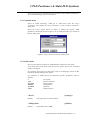
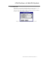
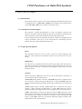
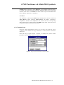
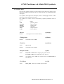
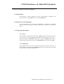
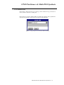
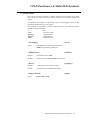
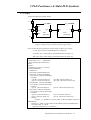
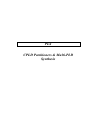
PLS
CPLD Partitioners & Multi-PLD
Synthesis
CPLD Partitioners & Multi-PLD Synthesis
Table of Contents
CPLD Partitioners & Multi-PLD Synthesis________________________________________ 1
1. Altera Specific Mapper _____________________________________________________________ 1
1.1. Introduction __________________________________________________________________ 1
1.2. Area/Speed oriented mapper ______________________________________________________ 1
1.3. PLS / MAXPLUS2 interface______________________________________________________ 2
1.3.1. From PLS to MAXPLUS2 ____________________________________________________ 2
1.3.1.1. EDIF netlist ____________________________________________________________ 2
1.3.1.2. AHDL file _____________________________________________________________ 2
1.3.2. From MAXPLUS2 to PLS ____________________________________________________ 2
1.4. Command menu _______________________________________________________________ 3
1.5. On-line mode _________________________________________________________________ 3
2. AMD Specific Mapper _____________________________________________________________ 5
2.1. Introduction __________________________________________________________________ 5
2.2. Area/Speed oriented mapper ______________________________________________________ 5
2.3. Target Specific Options _________________________________________________________ 5
2.4. Command menu _______________________________________________________________ 6
2.5. On-line mode _________________________________________________________________ 6
3. Cypress FLASH370 Specific Mapper __________________________________________________ 8
3.1. Introduction __________________________________________________________________ 8
3.2. Area/Speed oriented mapper ______________________________________________________ 8
3.3. Target Specific Options _________________________________________________________ 8
3.4. Command menu _______________________________________________________________ 9
3.5. On line mode ________________________________________________________________ 10
4. Lattice Specific Mapper____________________________________________________________ 11
4.1. Introduction _________________________________________________________________ 11
4.2. Area/Speed oriented mapper _____________________________________________________ 11
4.3. Target Specific Options ________________________________________________________ 11
4.4. Command menu ______________________________________________________________ 12
4.5. On-line mode ________________________________________________________________ 13
5. XILINX XEPLDs Specific Mappers __________________________________________________ 14
5.1. Introduction _________________________________________________________________ 14
5.2. Speed-Area oriented mapper_____________________________________________________ 14
5.3. Target Specific Options ________________________________________________________ 14
5.3.1. Device __________________________________________________________________ 14
5.3.2. Filling Ratio ______________________________________________________________ 14
5.4. Command menu ______________________________________________________________ 15
5.5. On-line mode ________________________________________________________________ 16
6. Multi-PLD Synthesis ______________________________________________________________ 17
6.1. Introduction _________________________________________________________________ 17
6.2. Multi-PLD Format ____________________________________________________________ 17
6.3. Example ____________________________________________________________________ 18
6.4. Multi-PLD synthesis using PLS __________________________________________________ 19
CPLD Partitioners & Multi-PLD Synthesis
CPLD Partitioners & Multi-PLD Synthesis
CPLD Partitioners &
Multi-PLD Synthesis
1. Altera Specific Mapper
1.1. Introduction
PLS performs synthesis and design optimization for PLD/CPLD devices from
Altera. An EDIF netlist or an AHDL file is generated when mapping on EP
Classic, MAX5000/7000/9000 devices. A PLDasm file is generated when
mapping on FLASHLogic device family.
1.2. Area/Speed oriented mapper
For classic EP and MAX devices, PLS performs minimization, factorization and
mapping on a virtual standard cell library. The resulting EDIF netlist or the
AHDL file is processed by Altera MAXPLUS2 tool in order to generate the final
programming device file.
For FLASHLogic devices, PLS performs minimization, factorization,
partitioning and mapping on a selected device. The resulting PLDasm file is
processed by Altera PLDshell tool.
CPLD Partitioners & Multi-PLD Synthesis - 1
CPLD Partitioners & Multi-PLD Synthesis
1.3. PLS / MAXPLUS2 interface
1.3.1. From PLS to MAXPLUS2
The output file from PLS is an AHDL file or an EDIF netlist, when mapping on
MAX5000/7000/9000 or EP classic devices.
1.3.1.1. EDIF netlist
To enter the EDIF netlist file generated by PLS as a project in MAXPLUS2,
choose the Project Name command from the File Menu. Then enter or select the
correct file name with the extension ".edf" (Important: The design name in the
netlist file must be identical to the file name of the netlist).
Specify also a library mapping file. By choosing the Interfaces menu, select the
EDIF Netlist Reader dialogue box and click on LMF #1 option. Write or select
the name "asyl.lmf". "asyl.lmf" is the library mapping file which may be located
in the current directory. Usually this file is in $ASYLDIR/lib directory. In this
case, specify the path to this file. Specify in User Libraries dialogue box from
the Options menu the path to "mf" directory of MAXPLUS2 files:
".../maxplus2/max2lib/mf". Select other options for logic synthesis processing:
target device, timing SNF extractor, EDIF output file, etc. Finally, to compile the
design, click on Start.
MAXPLUS2 reads the EDIF netlist, converts it to compiler netlist format,
performs minimization and optimization of the design, fits it into one or more
EPLDs and, finally, generates a programmer object file (.pof), an optional jedec
file (.jed), a fit file (.fit), a report file (.rpt) and others.
1.3.1.2. AHDL file
The AHDL file contains the Altera primitives gates. MAXPLUS2 processes this
file alone. Therefore, other files or library specifications are not needed.
1.3.2. From MAXPLUS2 to PLS
PLS is able to process an EDIF netlist generated by MAXPLUS2. This is an
EDIF simulation file (.edo) generated by MAXPLUS2 when selecting the EDIF
Netlist Writer from the Interfaces menu. In this case, MAXPLUS2 asks for an
EDIF Command File (.edc) which is located in ".../maxplus2/edc" directory. This
file is specific for each vendor. To generate an ".edo" file for PLS, specify the
"asyl.edc" file located in $ASYLDIR/lib directory. To process the ".edo" file of
MAXPLUS2 by PLS, specify the input netlist file name, the source technology
"altera", and the other associated parameters in PLS.
CPLD Partitioners & Multi-PLD Synthesis - 2
CPLD Partitioners & Multi-PLD Synthesis
1.4. Command menu
Select an Altera technology (Altera_EP, Altera_MAX5000, Altera_MAX7000,
Altera_9000, Altera_FLASHLogic) from the Target Technology menu within the
Target Parameters in the Synthesis Parameters window.
For Altera FLASHLogic you may also select Target Option button to define or
modify the specific parameters. The following window is displayed for Altera
FLASHLogic :
Figure 1: Target option selection for Altera FLASHLogic
CPLD Partitioners & Multi-PLD Synthesis - 3
CPLD Partitioners & Multi-PLD Synthesis
1.5. On-line mode
PLS can also perform synthesis on Altera families using the On-line mode.
In the main menu of the PLS, select the On-line option. The On-line command
window will appear.
For synthesis from high level description, refer to the language sections of this
manual for details about general options.
For synthesis on Altera EP and MAX devices the following specific parameters
can be defined:
-t
-tech
-ofmt
Altera
<max5000 | max7000 | max9000 | ep>
<Output Format>
• Output format
Value:
Default:
(-ofmt)
EDIF or AHDL.
The default value is EDIF.
For synthesis on FLASHLogic devices the following specific parameters can be
defined:
-t
-tech
-parttype
-fillratio
-partition
-ofmt
Intel
intel.lib
<Device name>
<Filling Ratio>
<Partition >
<Output Format>
• Device
(-parttype)
Value:
FX740_44, FX740_68, FX780_84, FX780_132 or FX8160_208.
Default:
The default value is FX8160_208.
• Filling Ratio
Default:
(-fillratio)
The default value is 100.
• Partition
(-partition)
Value:
YES or NO.
Default:
The default value is YES.
• Output format
Value:
Default:
(-ofmt)
PLDasm or DSL.
The default value is PLDasm.
CPLD Partitioners & Multi-PLD Synthesis - 4
CPLD Partitioners & Multi-PLD Synthesis
2. AMD Specific Mapper
2.1. Introduction
PLS performs AMD specific mapping with optional partitioning on multiple
PAL/MACH devices. The output file format is PALASM, DSL or EDIF. The
JEDEC file can easily be created using the AMD/MINC software.
2.2. Area/Speed oriented mapper
PLS performs a unique decomposition to create a speed/area trade-off. For this
purpose, the design is expressed using lexicographic expressions and an efficient
decomposition into sub functions with a limited number of inputs and product
terms.
Once the design has been decomposed into functions that can be mapped, PLS
fits it in the selected device, minimizing both the number of devices and the
depth in terms of design levels.
2.3. Target Specific Options
Device
This parameter allows the user to select a device for design mapping. The
"best_fit" option permits the automatic selection of the best device for your
design.
Filling Ratio
This parameter allows the user to control the filling ratio of each device. This
may be useful during routing through the switch matrix. It specifies the
percentage of macrocells to be used inside the device.
Partition
When selecting the YES option, the device will be partitioned, if necessary on
several instances of the selected device.
If PALASM output format is selected, a PALASM output file is created for each
device instance. When selecting the NO option, a single PALASM output file
will be generated. Warning messages indicate if the output file fits in the selected
device.
If DSL output format is selected, two files are created: a DSL output file, which
describes the whole design, and a .pia file which describes the design partitioning
(the grouping of the signals in the device instances). When selecting the NO
option, a single DSL output file is generated. Warning messages indicate if the
output file fits in the selected device.
If EDIF format is selected, a single EDIF file, on a standard virtual cell library,
is created. The netlist has been carefully optimized taking into account the
CPLD Partitioners & Multi-PLD Synthesis - 5
CPLD Partitioners & Multi-PLD Synthesis
structure of the device. The EDIF file can be used as input of MINC PLDesignerXL tool for JEDEC generation or simulation.
2.4. Command menu
Select an AMD technology (AMD_pal or AMD_mach) from the Target
Technology menu within the Target Parameters in the Synthesis Parameters
dialog box.
Select the Target Option button to define or modify the specific AMD
parameters. The display shown in figure 2 for an AMD_MACH is very similar to
that for AMD_PAL.
Figure 2: Target option selection for AMD_Mach
2.5. On-line mode
PLS can also perform synthesis on AMD families using the On-line mode.
In the main menu of the PLS, select the On-line option. The On-line command
window will appear.
For synthesis from high level description, refer to the language sections of this
manual for details about general options.
For synthesis on AMD devices the following specific parameters must be
defined:
-t
-tech
-parttype
-fillratio
-partition
-ofmt
<pal | mach>
<pal.lib | mach.lib>
<Device name>
<Filling Ratio>
<Partition >
<Output format >
• Device
Default:
(-parttype)
The largest device from the library.
• Filling Ratio
Default:
(-fillratio)
The default value is 100.
CPLD Partitioners & Multi-PLD Synthesis - 6
CPLD Partitioners & Multi-PLD Synthesis
• Partition
(-partition)
Value:
YES or NO.
Default:
The default value is YES.
• Output format
Value:
Default:
(-ofmt)
PALASM, DSL or EDIF.
The default value is PALASM.
CPLD Partitioners & Multi-PLD Synthesis - 7
CPLD Partitioners & Multi-PLD Synthesis
3. Cypress FLASH370 Specific Mapper
3.1. Introduction
PLS performs Cypress/FLASH370 specific mapping with optional partitioning
on multiple devices. An output file is generated for each device in VHDL format,
ready for place and route by CYPRESS WARP tool. A DSL output file may also
be obtained ready for place and route by MINC PLDesigner-XL.
3.2. Area/Speed oriented mapper
PLS performs a unique decomposition performing a speed/area trade-off. For this
purpose, the design is expressed using lexicographic expressions; and an efficient
decomposition into sub functions with a limited number of inputs and product
terms respecting the target device specification is performed.
Once the design has been decomposed into functions that can be mapped, PLS
fits it in the selected device, minimizing both the number of devices and the
depth in terms of design levels.
3.3. Target Specific Options
Device
This parameter allows the user to select a device for design mapping. The
"best_fit" option permits the automatic selection of the best device for your
design.
Filling Ratio
For each device, a parameter allows the control of the filling ratio of the device.
This may be useful for controlling the total area used inside the device, reserving
space for future extensions. It specifies the percentage of macrocells to be used
inside the device.
Partition
When selecting the YES option, the device will be partitioned, if necessary on
several instances of the selected device.
If VHDL output format is selected, a VHDL output file is created for each device
instance. When selecting the NO option, a single VHDL output file will be
generated. Warning messages indicate if the output file fits in the selected device.
If DSL output format is selected, two files are created: a DSL output file, which
describes the whole design, and a .pia file which describes the design partitioning
(the grouping of the signals in the device instances). When selecting the NO
option, a single DSL output file is generated. Warning messages indicate if the
output file fits in the selected device.
CPLD Partitioners & Multi-PLD Synthesis - 8
CPLD Partitioners & Multi-PLD Synthesis
3.4. Command menu
Select the Cypress_FLASH370 technology from the Target Technology menu
within the Target Parameters in the Synthesis Parameters dialog box.
Select the Target Option button to define or modify the specific FLASH370
parameters. The following window is displayed:
Figure 3: Selecting Cypress FLASH370 target technology options
CPLD Partitioners & Multi-PLD Synthesis - 9
CPLD Partitioners & Multi-PLD Synthesis
3.5. On line mode
PLS can also perform synthesis on FLASH370 families using the On-line mode.
In the main menu of the PLS, select the On-line option. The On-line command
window will appear.
For synthesis from high level description, refer to the language sections of this
manual for details about general options.
For synthesis, the following specific parameters can be defined:
-t
-tech
-parttype
-fillratio
-partition
-ofmt
Cypress
cypress.lib
<Device name>
<Filling Ratio>
<Partition>
<Output format>
• Device
Default:
(-parttype)
The largest device from the library.
• Filling Ratio
Default:
(-fillratio)
The default value is 100.
• Partition
(-partition)
Value:
YES or NO.
Default:
The default value is YES.
• Output format
Value:
Default:
(-ofmt)
VHDL or DSL.
The default value is VHDL.
CPLD Partitioners & Multi-PLD Synthesis - 10
CPLD Partitioners & Multi-PLD Synthesis
4. Lattice Specific Mapper
4.1. Introduction
PLS performs Lattice ((i)pLSI, GAL) specific mapping with optional partitioning
on multiple devices. A LDF, DSL or EDIF file is created for each (i)pLSI device
and a PALASM or DSL file is created for each GAL device.
4.2. Area/Speed oriented mapper
PLS performs a unique decomposition to create a speed/area trade-off. The
design is expressed using lexicographic expressions and efficient decomposition
into sub functions with a limited number of inputs and product terms.
Once the design has been decomposed into functions that can be mapped into the
Lattice architecture, PLS fits it in the selected device, minimizing both the
number of devices and the depth of design levels.
4.3. Target Specific Options
Device
This parameter allows the user to select a device for design mapping. The
"best_fit" option permits the automatic selection of the best device for your
design.
Filling Ratio
For each device, a parameter allows the control of the filling ratio of the device.
This may be useful for controlling the total area used inside the device, reserving
space for future extensions. It specifies the percentage of macrocells to be used
inside the device.
Partition
When selecting the YES option, the device will be partitioned, if necessary on
several instances of the selected device.
If PALASM output format is selected, a PALASM output file is created for each
device instance. When selecting the NO option, a single PALASM output file
will be generated. Warning messages indicate if the output file fits in the selected
device.
If LDF output format is selected, a LDF output file is created for each device
instance. When selecting the NO option, a single LDF output file will be
generated. Warning messages indicate if the output file fits in the selected device.
If DSL output format is selected, two files are created: a DSL output file, which
describes the whole design, and a .pia file which describes the design partitioning
(the grouping of the signals in the device instances). When selecting the NO
option, a single DSL output file is generated. Warning messages indicate if the
output file fits in the selected device.
CPLD Partitioners & Multi-PLD Synthesis - 11
CPLD Partitioners & Multi-PLD Synthesis
If EDIF format is selected, a single EDIF file, on a standard virtual cell library,
is created. The netlist has been carefully optimized taking into account the
structure of the device. The EDIF file can be used as input of LATTICE fitter
tool for JEDEC generation or simulation.
Use Macro
This parameter is valid only for EDIF output format and its value is restricted to
Lattice_Macros. When selecting Lattice_Macros, the adders, substractors,
comparators, decoders and multiplexers are inferred and the corresponding
Lattice macro blocs are instanciated in the EDIF output netlist. These macros are
recognized and processed by the Lattice fitter.
4.4. Command menu
Select the Lattice technologies (Lattice_gal or Lattice_plsi) from the Target
Technology menu within the Target Parameters in the Synthesis Parameters
dialog box.
Select the Target Option button to define or modify the specific Lattice
parameters. The following window is displayed.
Figure 4: Target option selection for Lattice pLSI
CPLD Partitioners & Multi-PLD Synthesis - 12
CPLD Partitioners & Multi-PLD Synthesis
4.5. On-line mode
PLS can also perform synthesis on Lattice family using the On-line mode. In the
main menu of the PLS, select the On-line option. The On-line command window
will appear.
For synthesis from high level description, refer to the language sections of this
manual for details about general options.
For synthesis on Lattice devices the following specific parameters must be
defined:
-t
-tech
-parttype
-fillratio
-partition
-ofmt
-b_lib
lattice
<plsi.lib | gal.lib>
<Device name>
<Filling ratio>
<Partition>
<Output format>
Lattice_Macros
• Device
(-parttype)
Default:
The largest device from the library.
• Filling Ratio
Default:
(-fillratio)
The default value is 100.
• Partition
(-partition)
Value:
YES or NO.
Default:
The default value is YES.
• Output Format
(-ofmt)
Value:
LDF, DSL or EDIF when mapping on (i)pLSI devices.
PALASM or DSL when mapping on GAL devices.
Default:
The default value is LDF for (i)pLSI devices and PALASM for
GAL devices
• Use Macro
Value:
(-b_lib)
lattic_m.lib, valid only for EDIF output format.
CPLD Partitioners & Multi-PLD Synthesis - 13
CPLD Partitioners & Multi-PLD Synthesis
5. XILINX XEPLDs Specific Mappers
5.1. Introduction
PLS performs a specific mapping on Xilinx 7000 families of XEPLDs. The
output is either a single XNF file or a set of PALASM files.
5.2. Speed-Area oriented mapper
For the XC7000 series, the design optimization is obtained by dedicated
minimization and factorization techniques tailored to the features of the XC7000
series.
5.3. Target Specific Options
5.3.1. Device
This parameter is useful when generating a XNF output file and allows the user
to select a device for design mapping. By default, the largest device is selected.
When generating a PALASM output files, a generic XEPLD chip name is
automatically generated in the top level PLUSASM interconnection file (.pld).
5.3.2. Filling Ratio
This parameter allows the user to control the filling ratio of PAL devices. It is
only available when generating PALASM output files. It specifies the percentage
of macrocells to be used inside the device.
CPLD Partitioners & Multi-PLD Synthesis - 14
CPLD Partitioners & Multi-PLD Synthesis
5.4. Command menu
Select Xilinx_7000 in the Target Technology menu within the Target Parameters
in the Synthesis Parameters dialog box.
Select the Target Option button define or modify the specific Xilinx parameters.
The following display corresponds to the Xilinx 7000 XEPLDs:
Figure 5: Target option selection for Xilinx XC7000
CPLD Partitioners & Multi-PLD Synthesis - 15
CPLD Partitioners & Multi-PLD Synthesis
5.5. On-line mode
PLS can also perform synthesis on Xilinx using the On-line mode. In the main
menu of the PLS, select the On-line option. The On-line command window will
appear.
For synthesis from high level description, refer to the language sections of this
manual for details about general options.
For synthesis or optimization of Xilinx XEPLD devices, the following specific
parameters must be defined:
-t
-tech
-parttype
-fillratio
-ofmt
PAL
<PAL.lib | 7000>
<Device name>
<Filling Ratio>
<Output format>
• Technology
Value:
(-tech)
PAL.lib when generating PALASM files,
7000 when generating a XNF file.
• Filling Ratio
(-fillratio)
Default:
The default value is 100.
Remark:
Available only for PLUSASM output format.
• Device
(-parttype)
Default:
The largest device from the library.
Remark:
Available only for XNF output format.
• Output Format
Value:
(-ofmt)
PLUSASM or XNF.
CPLD Partitioners & Multi-PLD Synthesis - 16
CPLD Partitioners & Multi-PLD Synthesis
6. Multi-PLD Synthesis
6.1. Introduction
In some cases, a designer may want to describe a design in an hierarchical way,
using either the same or different description language for each piece of the
design. In other cases, the designer may be faced with the problem of resynthesizing a design represented by a set of separate files using different
languages. For example a set of PALASM files, corresponding to an already
existing PLD design that has to be moved to a single FPGA.
In order to allow the capture of such designs, PLS offers the Multi-PLD PLS
description format. This format allows the specification of a top level netlist that
describe the interconnection of design portions, each design portion being
specified either in the PALASM or OpenABEL formats.
Once Multi-PLD designs have been entered in PLS, the different portions will be
merged and mapped on the selected target technology.
6.2. Multi-PLD Format
The syntax of the Multi-PLD format is the following:
<Multi-PLD file> ::=
top "=" <File Name in EDIF Format> ";"
(<For Declaration>) +
<For Declaration> ::=
FOR <Portion Name> USE <File Name> FORMAT [<Format>]
[ENTITY <entity>] [ARCHITECTURE <architecture>] [WORK
<work_lib>] ";"
<Format> ::=
PALASM / OpenABEL / VHDL
Remark: ENTITY, ARCHITECTURE and WORK are required only for
VHDL format (they may be truncated to the first three characters, for instance
ENT).
Figure 6: Syntax for Multi-PLD format
For each instance in the design described in a separate file, in PALASM,
OpenABEL, ..., format, a "FOR..." line must be defined that makes the link
between the EDIF cell name of the instance and the specification file.
Assume for example that an instance INS1 of a cell CELL1 is described in a file
cell1.pds in PALASM format, then the following line is required:
FOR CELL1 USE cell1.pds FORMAT PALASM ;
The Multi-PLD format is explained more deeply in the following section using a
complete example.
CPLD Partitioners & Multi-PLD Synthesis - 17
CPLD Partitioners & Multi-PLD Synthesis
6.3. Example
Assume the following simple design:
C
I_2_PDS1
I_1_INVERT
A1
AA
B1
B2
ZN
File:
pds1.pds
O
A
File:
invert.pds
B
Figure 7: Simple design with mixed input design formats
Also, assume that the specification of this design is made up of 3 parts:
- vs.edn: top level netlist in EDIF format (see figure 8)
- invert.pds: part 1 of the design, PALASM format (see figure 9)
- pds1.pds: part 2 of the design, PALASM format (see figure 10).
(edif simple
(edifversion 2 0 0)
(ediflevel 0)
(keywordmap (keywordlevel 0))
(status
(written
(timeStamp 94 08 19 17 18 46)))
(Library DESIGNS
(ediflevel 0)
(technology (numberdefinition))
(cell PDS1 (celltype GENERIC)
(view netlist (viewtype NETLIST)
(interface
(port B1 (direction INPUT))
(port B2 (direction INPUT))
(port A1 (direction INPUT))
(port ZN (direction OUTPUT)))))
(cell INVERT (celltype GENERIC)
(view netlist (viewtype NETLIST)
(interface
(port A (direction INPUT))
(port O (direction OUTPUT)))))
(cell simple (celltype GENERIC)
(view netlist (viewtype NETLIST)
(interface
(port aa (direction INPUT))
(port b (direction INPUT))
(port c (direction INPUT))
(port f3 (direction OUTPUT)))
(contents
(instance I_1_INVERT (viewref netlist (cellref INVERT (libraryref
DESIGNS))))
(instance I_2_PDS1 (viewref netlist (cellref PDS1 (libraryref DESIGNS))))
(net DEF_NET_4 (joined
(portref O (instanceref I_1_INVERT))
CPLD Partitioners & Multi-PLD Synthesis - 18
F3
CPLD Partitioners & Multi-PLD Synthesis
(portref f3)))
(net DEF_NET_6 (joined
(portref ZN (instanceref I_2_PDS1))
(portref A (instanceref I_1_INVERT))))
(net DEF_NET_8 (joined
(portref c)
(portref A1 (instanceref I_2_PDS1))))
(net DEF_NET_10 (joined
(portref b)
(portref B2 (instanceref I_2_PDS1))))
(net DEF_NET_12 (joined
(portref aa)
(portref B1 (instanceref I_2_PDS1))))))))
(comment "Reference To The Cell Of Highest Level")
(design PCB (cellref simple (libraryref DESIGNS))))
Figure 8: EDIF file vs.edn
CHIP INVERT USER
AO
EQUATIONS
O =/A
Figure 9: Sub-module PALASM file invert.pds
CHIP PDS1 USER
A1 B1 B2 ZN
EQUATIONS
ZN = /(A1*B1*B2)
Figure 10: Sub-module PALASM file pds1.pds
Then the following file allows the capture of the design into PLS:
top = vs.edn;
for PDS1 use pds1.pds format palasm;
for INVERT use invert.pds format palasm;
Figure 11: Top-level Multi-PLD file to merge VS , PDS1 & INVERT in ASYL
6.4. Multi-PLD synthesis using PLS
From the command menu of the Graphical User Interface (GUI), select the
execute menu. Select from the list of available inputs (Input Format) the MultiPLD format. The selected file name must be in the Multi-PLD format described
above.
Then using the selection boxes, select all other appropriate synthesis parameters,
including the target technology. Refer to the technology pages of the user manual
for details on the technology specific options.
CPLD Partitioners & Multi-PLD Synthesis - 19