1
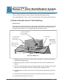
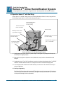
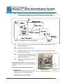
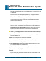
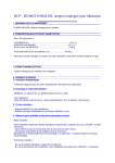
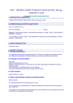
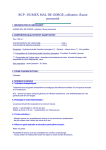
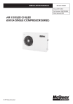
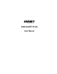
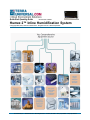
Quick-Start Operating Guide
Document No. 1800-69
Humex 2™ Inline Humidification System
© Copyright 2010, 2011, 2012 Terra Universal Inc. All rights reserved. • Revised April 2012
Terra Universal, Inc. • TerraUniversal.com • 800 S. Raymond Ave. • Fullerton, CA 92831 • TEL: (714) 578-6000 • FAX: (714) 578-6020
Quick-Start Operating Guide
Humex 2™ Inline Humidification System
© Copyright 2012 Terra Universal Inc. All rights reserved. • Revised April 2012 • Document No. 1800-69v2.0tm
Proprietary Notice
This manual pertains to proprietary devices manufactured by Terra
Universal, Inc. Neither this document nor any portion of it may be
reproduced in any way without prior written permission from Terra
Universal.
Terra Universal makes no warranties applying to information contained
in this manual or its suitability for any implied or inferred purpose.
Terra Universal shall not be held liable for any errors this manual
contains or for any damages that result from its use.
Safety Notice
A thorough familiarity with all operating guidelines is essential to safe
operation of the product. Failure to observe safety precautions could
result in poor performance, damage to the system or other property, or
serious bodily injury or death.
Cautions are used when failure to observe instructions
could result in significant damage to equipment.
CAUTION
The following symbols are intended to call your attention to two levels
of hazard involved in operation:
Warnings are used when failure to observe instructions
or precautions could result in injury or death.
WARNING
The information presented here is subject to change without notice.
1.0 Introduction
This manual provides information on installing and operating your Terra ErgoHeight™ Work Station.
By studying this document carefully, you can be assured of a long, efficient service life from your system.
2.0 Description
The Humex 2™ Humidifier provides inline humidification of nitrogen or other process gas being fed into a glove box or
similar enclosure.
During operation, a 20W resistance heater inside the Humex 2 vaporizes incoming water fed into a stainless steel
chamber. Process gas, which enters the Humex 2 through separate .25"-diameter flexible tubing, is humidified as it
passes through this chamber on its way to a glove box or other enclosure.
The Humex 2™ humidity sensor, installed inside the remote enclosure, monitors the relative humidity level. As soon
as the %RH falls below a user-selected threshold, a relay inside the Humex activates the heater and a solenoid that
turns on the water flow. When the %RH set point is attained, the Humex turns off heater and water flow.
Operation with the Dual Purge
For optimal efficiency—and to conserve nitrogen— the
Humex can be operated with Terra’s Dual Purge™
Variable Purge Controller.
In this configuration the Humex issues a signal to the
Dual Purge, via a 4-connector low-voltage cable, to
initiate high flow (bypassing the Dual Purge flowmeter)
whenever the humidity falls below the set point. This
high flow of process gas quickly humidifies the
enclosure.
Terra Universal, Inc. • TerraUniversal.com • 800 S. Raymond Ave. • Fullerton, CA 92831 • TEL: (714) 578-6000 • FAX: (714) 578-6020
2
Quick-Start Operating Guide
Humex 2™ Inline Humidification System
© Copyright 2012 Terra Universal Inc. All rights reserved. • Revised April 2012 • Document No. 1800-69v2.0tm
When the set point is attained, the Humex deactivates the high flow (as well as the Humex humidification system) to
conserve on nitrogen. In this low-flow purge, the flow rate is restricted by the Dual Purge flowmeter.
Refer to Operating Manual No. 1800-42 or 1800-13 for further information on Terra’s Glove Box Dual Purge System.
3.0 Set Up and Operation: Humex 2™ without Dual Purge
Humex 2™ Set Up
Includes: Humex 2™ controller (Part No. 9081-02), humidity sensor (Part No. 9500-02A), 120VAC power cord, 12DC
power supply and cord, pinch valve assembly, water filter, humidity sensor cable, Door Switch jumper (installed on
rear panel), 0-20 SCFH flowmeter, .25" clear urethane tubing. Refer to illustration on page 2.
To Water Filter/Pinch
Valve Assembly
1/4"-dia. tubing
120VAC Power
To 12VDC Power
Supply (Phone
jack connector)
Regulated Gas
Supply (35 psi;
15 – 20 SCFH);
1/4"-dia. tubing
Humidity Sensor
Cable (3-pin DIN
connector)
Set Up for Humex 2™
2.1. Carefully unpack the unit and check for any visible damage or missing parts. Any damage should be reported
immediately to the shipping company.
2.2. Make sure that your glove box is placed on a level, stable surface, away from heat or chemicals that could
damage it.
2.3. Using 0.25" clear urethane tubing, connect your in-house gas supply to the “Gas In” bulkhead on the rear panel
of the Humex 2 by loosening the Poly-Tite collar, inserting the tubing, and tightening the collar.
2.4. Use another length of 1/4" tubing to connect “Gas Out” on the rear panel to the gas inlet of the enclosure to be
monitored.
2.5. Connect the pinch valve assembly into the exit side of the water filter and the “Water” port on the rear panel.
2.6. Connect the water filter inlet side to a water source.
Terra Universal, Inc. • TerraUniversal.com • 800 S. Raymond Ave. • Fullerton, CA 92831 • TEL: (714) 578-6000 • FAX: (714) 578-6020
3
Quick-Start Operating Guide
Humex 2™ Inline Humidification System
© Copyright 2012 Terra Universal Inc. All rights reserved. • Revised April 2012 • Document No. 1800-69v2.0tm
2.7. Connect one of the 3-pin DIN connectors of the RH sensor to the “R/H Sensor” port on the rear panel, and the
other end to the “R/H Sensor” port of the glove box.
2.8. Plug the power cord to a grounded 120VAC receptacle. Plug the other end into the “120VAC” connector on the
rear panel.
2.9. Plug the 12VDC power supply into a grounded 120VAC receptacle. Plug the phone jack connector into the
“Purge Control” port on the rear of the Humex 2 controller.
2.10.
Initial Humex 2™ Programming
Unplug the 12VDC power connector (phone jack). Hold down the SET button while reconnecting the 12VDC
connector to turn ON power to the Humex 2. The set button is the left-most button on the front control panel.
Repeatedly pressing SET will advance through these alarm displays. Use UP/DOWN buttons to change default
settings (show in parentheses). See steps below for more information on each setting.
DOOR
Open Door Delay Alarm (60 seconds) – used only for multi-door cabinets with door sensor switches.
For glove boxes, a jumper is installed in the “Door Switch” port to deactivate this alarm.
rH
Relative Humidity Set Point Alarm (60 seconds) – the number of seconds that the %RH level must be
below the humidity set point before alarm is activated.
bEEP
Enables and disables beeper.
hU
Humex/NitroWatch Alarm Mode – toggles back and forth between operation mode for Humex 2™
Humidifier and NitroWatch® Low-Humidity systems. When the “hU” mode is ON, the system activates
the rH alarm when the measured %RH level remains below the set point for the specified time
(appropriate to humidification applications). When the “hU” mode if OFF, the system activates the rH
alarm when the measured %RH level remains above the set point for the specified time (appropriate to
dehumidification applications).
Add
Calibration Adjust Mode – adds a supplemental numerical value (positive or negative) to the measured
%RH to allow calibration of the device to an NIST-certified or other RH meter.
Alr
Alarm Timers – lets you select minutes (“Long”) or seconds (“SHrt”) as the time scale for all alarm
functions.
Once you enter the SET mode, use these guidelines to change any defaults:
2.11. Door The display will indicate “door” until the set button is released. The value displayed is the
number of seconds that the door must be open before an OPEN DOOR alarm will be activated. Use
the UP and DOWN buttons to set this value. Press the SET button to finish and move to the next
parameter.
2.12
rH
The display will indicate “rH” until the set button is released. The value displayed is the number of
seconds that the R/H input must be below the set point when in the Humex mode before a LOW RH
alarm will be activated. Use the UP and DOWN buttons to set this value. Press the SET button to finish
and move to the next parameter.
Terra Universal, Inc. • TerraUniversal.com • 800 S. Raymond Ave. • Fullerton, CA 92831 • TEL: (714) 578-6000 • FAX: (714) 578-6020
4
Quick-Start Operating Guide
Humex 2™ Inline Humidification System
© Copyright 2012 Terra Universal Inc. All rights reserved. • Revised April 2012 • Document No. 1800-69v2.0tm
Note: The “Nitrowatch” mode allows operation of the RH sensor with Terra’s NitroWatch® low-humidity
controller. In this mode, a HIGH R/H alarm is activated when the R/H input is above the set point.
2.13
bEEP The display will indicate “bEEP” until the set button is released. The display will indicate “on” or “off.”
Use the UP and DOWN buttons to change this value. ON indicates that the beeper will be activated
when an alarm occurs. OFF indicates that the beeper is disabled. Press the SET button to finish and
move to the next parameter.
2.14 Hu
The display will indicate “hU” until the set button is released. Use the UP and DOWN
buttons to change the displayed value: ON indicates HUMEX mode (humidification); OFF
indicates NITROWATCH mode (dehumidification).
2.15 Add The display will indicate a supplemental value that the Humex will “Add” to the measured
RH. This value adjusts the R/H reading to allow manual calibration to an independent
humidity sensor or calibration device. Use the UP and DOWN buttons to set this value,
which can be positive or negative. Press the SET button to finish and exit the setup mode.
Note: the “Add” value will wrap around if the maximum or minimum value is exceeded. For example,
if you try to set the supplemental adjustment value above 49.5, the value will wrap around to -50.
A side effect of using an adjust value other than zero is that the R/H range will be reduced. For
example, if the adjust value is -10, then the maximum R/H value that can occur is 90 because the
input value (100) will be added to the adjust value before the system uses it.
2.16 Alr
The display will indicate “Alr” until the set button is released. This is the
MINUTES/SECONDS selector for the alarm timers. Use the UP and DOWN buttons to
change this setting. The display will indicate “Long” for MINUTES and “SHrt” for
SECONDS. Press the SET button to finish.
Press SET once more to advance to Normal Run Mode. You should view the current %RH level inside
the glove box.
Make a mistake? No Problem!
To reset the system, turn the system OFF while in setup mode and restart while holding the SET button.
Humex 2™ Operation
After completing the set-up programming steps above, enter SET to view the current % RH set point. Use
the UP/DOWN keys to change this value. Press SET again to return to Normal Run Mode and view
current % RH.
Beeper Silencing – Press any front panel button to silence the beeper during an alarm condition.
The Humex 2™ will now turn ON a low flow of water and activate the heater to introduce water vapor
into the glove box whenever the % RH falls below the set point. When the set point is attained, this
moisture flow is terminated.
Terra Universal, Inc. • TerraUniversal.com • 800 S. Raymond Ave. • Fullerton, CA 92831 • TEL: (714) 578-6000 • FAX: (714) 578-6020
5
Quick-Start Operating Guide
Humex 2™ Inline Humidification System
© Copyright 2012 Terra Universal Inc. All rights reserved. • Revised April 2012 • Document No. 1800-69v2.0tm
4.0 Operation: Humex 2™ with Dual Purge
Includes: Humex 2™ controller , humidity sensor, and connecting lines listed in Section 2.0 above, along with Glove
Box Dual Purge System (Part No. 1603-57). Refer to illustration on page 3.
To Water Filter/Pinch
Valve Assembly
1/4"-dia. tubing
12VDC Phone-Jack
Power Connector
120VAC Power
Humidity Sensor Cable
(3-pin DIN connector)
Cabinet Pressure Line
(1/4"-dia. tubing)
Humidified Gas In to Cabinet
(1/4"-dia. tubing)
Regulated Gas Supply (35
psi; 15 - 20 SCFH)
To Nitrogen Supply
(1/4"-dia. tubing)
Set Up for Humex 2™ with Dual Purge™ System
3.1. Carefully unpack the unit and check for any visible damage or missing parts. Any damage should be reported
immediately to the shipping company.
3.2. Make sure that your glove box is placed on a level, stable surface, away from heat or chemicals that could
damage it.
3.3. Complete the Humex 2™ and Dual Purge System connections as indicated in the illustration. Note: The PURGE
CONTROL connection allows the Humex 2™ to draw power from and to control the Dual Purge System.
3.4. Leave the jumper cable connected to the DOOR SWITCH port on the Humex. This connection is used only in
desiccator applications.
3.5. Dual Purge Programming
Turn ON the Dual Purge System while depressing SET (the left button on the front control panel). Each time you
release and then press and hold SET, you will advance through the following control functions. Use UP/DOWN
to change default settings (included in parentheses):
Terra Universal, Inc. • TerraUniversal.com • 800 S. Raymond Ave. • Fullerton, CA 92831 • TEL: (714) 578-6000 • FAX: (714) 578-6020
6
Quick-Start Operating Guide
Humex 2™ Inline Humidification System
© Copyright 2012 Terra Universal Inc. All rights reserved. • Revised April 2012 • Document No. 1800-69v2.0tm
Prg
Purge Delay: The Dual Purge System senses the internal cabinet pressure and activates a high-flow
purge when this pressure falls below a set level. The “Prg” setting lets you specify the number of
seconds the high purge remains active after internal glove box pressure level is restored (default: 60).
Humex 2™/Dual Purge™ System Operation
door
Number of seconds a door must remain open to activate the OPEN DOOR alarm (default: 60). Inactive
in Glove Box applications.
bEEP
Enables and disables beeper (default: ON).
Glo
Activates GLOVE BOX control mode: press UP to turn ON and proceed to glove box pressure setting;
DOWN to turn OFF (default: ON).
Press
In GLOVE BOX mode, this setting lets you adjust
the pressure (milli-inches WG) at which the high
purge is activated (default: 0.2).
Done
Settings are complete; press SET once more to
begin operation.
Solenoid
Make a mistake? No Problem! To reset the system, turn the
system OFF while in setup mode and restart while holding the
SET button.
Heater
wires
Heater
Humex 2™ Operation with the Dual Purge™ System
3.6 Operation Display
Functions: After completing initial programming, press the
specified button to view these operating conditions:
Humex 2 Interior
(viewed from left side)
Vaporization
Chamber
High Purge Bypass – Press and hold SET
Terra Universal, Inc. • TerraUniversal.com • 800 S. Raymond Ave. • Fullerton, CA 92831 • TEL: (714) 578-6000 • FAX: (714) 578-6020
7
Quick-Start Operating Guide
Humex 2™ Inline Humidification System
© Copyright 2012 Terra Universal Inc. All rights reserved. • Revised April 2012 • Document No. 1800-69v2.0tm
In some applications (especially using fine powders in a glove box), you may wish to deactivate the high purge
function, which could create turbulence. To do so, press DOWN while holding SET. To activate high purge, hold
UP while holding SET.
Incoming Line Pressure – Press & hold UP (displays line pressure in PSI). Turn the pressure regulator (the
round knob on the right side of the Dual Purge control panel) until the pressure gauge reads between 30 and 40
psi (use more pressure for larger glove boxes with 4 or more arm ports).
Internal Pressure – Press and hold DOWN (displays in milli-inches of WG).
The Dual Purge System includes a flowmeter, which provides a continuous low-level purge to maintain a
constant positive pressure inside the cabinet.
If continuous purging is desired, set the flowmeter so that the pressure gauge reads at least 0.1" WG when the
system is in low purge state.
If continuous purging is not required, close the flowmeter. The Dual Purge System will initiate a purge only when
an air lock door is opened, or when humidity level falls below the set point (if your system includes a Humex 2).
Purge Delay Timer – Press and hold UP and DOWN simultaneously to review the number of seconds the
high-flow purge is active after the internal pressure set point is established. To change this value, see
“Programming,” above.
CAUTION!:
Because the high-level purge fed into the system can lead to excessive internal pressure,
you must equip a glove box with an Automatic RB Valve when you install a Dual Purge
System.
3.7 Turn the Dual Purge System ON by placing the power switch in the “up” position. The Humex 2™ LED display
should indicate some humidity level.
NOTE: Allow about 5 minutes for the system to warm up after turning power “ON.”
3.8 Proceed with the Humex 2™ set up and programming procedures detailed in steps 2.1 through 2.16 above.
Make a mistake? No Problem! To reset the system, cut power to the Humex 2™ by turning the Dual Purge System
OFF while in setup mode and restart while holding the SET button.
3.9 Adjust Humidity Set Point: After completing initial programming, press the SET button to view the current %
RH set point. Use the UP/DOWN keys to change this set point.
3.10 Beeper Silencing: Press any front panel button to silence the beeper during an alarm condition.
The Humex 2™ will now activate high-flow purging whenever the %RH level inside the glove box falls below the
specified set point. Your system is ready for operation.
Operating Tips
•
If too much sputtering of water occurs in the process chamber during Humex 2 operation, decrease the water
supply by incrementally closing the pinch valve.
Terra Universal, Inc. • TerraUniversal.com • 800 S. Raymond Ave. • Fullerton, CA 92831 • TEL: (714) 578-6000 • FAX: (714) 578-6020
8
Quick-Start Operating Guide
Humex 2™ Inline Humidification System
© Copyright 2012 Terra Universal Inc. All rights reserved. • Revised April 2012 • Document No. 1800-69v2.0tm
•
If the %RH does not rise after 3 – 5 minutes of Humex 2 operation, open the pinch valve incrementally to
increase water flow.
•
Keep the “gas out” line from the Humex 2 to the process chamber as short as possible.
•
If the Dual Purge System remains at high-level purge, or if it frequently fluctuates between high and low-level
purge, you need to increase your flowmeter setting. Increase the flowmeter setting until the humidity level falls a
few percent below your set point. At this flowmeter setting, the system will be able to maintain the desired
humidity while on the low-level purge—and save nitrogen.
As you increase the flow, the internal positive pressure will also increase. You may safely increase this pressure
as high as .3" WC as long as the chamber incorporates Automatic RB Valves, which automatically protect
against the possibility of warping or explosion.
5.0 Maintenance
Replacing Heater
The Humex 2 heater has a MTBF (mean time before failure) rating of 500 hours, equivalent to years of typical
operation. If the heater needs to be replaced,
4.1 Remove the sheet metal screws to remove the top cover.
4.2 Use a 7/16" wrench to loose the fittings around the heater.
4.3 Remove the tubing elbows by loosening the fittings at both ends (see illustration)
4.4 Undo the heater wires (one at the relay, the other at the terminal block)
4.5 Install new heater, using reverse procedure.
Replacement Heater
Cat. #
9081-05
Replacement Filter
9081-06
Activated charcoal filter, attached to incoming water line
Terra Universal, Inc. • TerraUniversal.com • 800 S. Raymond Ave. • Fullerton, CA 92831 • TEL: (714) 578-6000 • FAX: (714) 578-6020
9
Quick-Start Operating Guide
Humex 2™ Inline Humidification System
© Copyright 2012 Terra Universal Inc. All rights reserved. • Revised April 2012 • Document No. 1800-69v2.0tm
6.0 Specifications
See separate QuickStart (Doc. No. 1800-42 or 1800-13) for further specifications on Terra’s Dual Purge
System and Glove Boxes
Dimensions:
12"W x 11.25"D x 7"H
Weight:
16 lbs.
Power
12 V/DC (from Dual Purge or 12VDC supply) for electronics; 120VAC for heater
Sensor Dimensions:
1.5" x .75" x 4"
Case Material:
Stainless steel
Water Line Pressure:
5 - 35 psi
Water Filter:
Activated charcoal
Flow*:
15 CFH (optimal); 30 CFH max. (high flow purge when used with Dual Purge System)
Gas Line Pressure:
Should be externally regulated between 20 – 35 psi**
Humidification Rate:
35% RH / Cu. Ft. of enclosure / hour
Humidity Display:
3 1/2 digit LED display
Electrical Connections: Screw terminals
Humidity Output:
0–5V
Measuring Range:
0 – 100% RH
Accuracy (at 20° C):
± 2% RH
Display Resolution:
± .1% RH
Temp. Dependence:
± .04% RH/°C
Sensor Calibration:
None required. Calibration (“Add”) mode allows %RH readout adjustment to independent
calibration source, if required.
Heater:
20W, 120VAC resistance heater in SS housing; 1.25" x .25
Water Solenoid:
6W
Fuse:
4A
* Flow should be externally regulated between 5 – 20 CFH, either using the Dual Purge flowmeter or separate
flowmeter.
** User-furnished regulator or Dual Purge System required for gas pressure regulation
Terra Universal, Inc. • TerraUniversal.com • 800 S. Raymond Ave. • Fullerton, CA 92831 • TEL: (714) 578-6000 • FAX: (714) 578-6020
10
Quick-Start Operating Guide
Humex 2™ Inline Humidification System
© Copyright 2012 Terra Universal Inc. All rights reserved. • Revised April 2012 • Document No. 1800-69v2.0tm
7.0 Warranty
Products Manufactured by Terra: Terra Universal, Inc., warrants products that it manufactures to be free from
defects for a period of 12 months for parts and 90 days for labor, commencing from the date of shipment. Terra’s
sole responsibility is to repair or replace, at its option, any part of the product that proves defective or malfunctioning
during this time limit. In some cases, components incorporated in Terra Universal products are covered by additional
warranties from component manufacturers; obtain specific information from Terra sales representatives. This
warranty is void if the equipment is abused or modified by the customer, is operated outside Terra’s operating
instructions or specifications, or is used in any application other than that for which it is specified. This warranty does
not include routine maintenance or service procedures, breakage of quartz baths after 60 days, shipping damage,
nor damage from misuse, intentional or unintentional abuse, neglect, natural disasters, or acts of God.
Products Manufactured by Others: Terra Universal, Inc., warrants that, to the best of its ability, Terra’s
representations of products that are manufactured by others reflect the manufacturer’s representations, subject to
change without notice. Sole warranty for these products is the original manufacturer’s warranty that is passed
forward to the purchaser and constitutes the customer’s sole remedy for these products. Detailed warranties for
distributed products are available through Terra sales representatives.
Freight Shortage or Damage: Upon receipt of any equipment from Terra Universal, Inc., customer shall
immediately unpack and inspect for damage or shortage. The customer shall not accept a damaged package or a
short shipment until the carrier makes a "damage or shortage" notation on both the carrier's and customer's copy of
the freight bill or delivery receipt. Service title passes when the shipment is loaded, so customer is responsible for
filing and collecting a freight claim. Any replacement products must be ordered and paid for separately. For Terra's
"Policy and Procedures for Returning Goods," see Terra's Internet site: www.TerraUniversal.com.
Generally, customers can improve the chance of collecting on a freight claim by following these procedures: 1)
formally requesting that the carrier inspect the shipment immediately upon suspecting damage or shortage to verify
condition; 2) notifying the carrier upon discovery of concealed damage and requesting an inspection within 15 days
of receipt, both in person or phone and following up via mail; 3) keeping the shipment as intact as possible, including
retaining original packaging materials and keeping the product as close to the original receiving location as possible;
4) holding salvage for disposition by the carrier.
All Claims: Terra Universal expressly disclaims all other warranties, expressed or implied or implied by statute,
including the warranties of merchantability or fitness for intended use. Terra Universal is not responsible for
consequential or incidental damages arising out of the purchase or use of the products supplied by Terra Universal.
Terra Universal is not liable for damage to facilities, other equipment, products, property or personnel of others, or of
their agents, suppliers, or affiliated parties, which is caused or alleged to have been caused by products supplied by
Terra Universal. In any event or series of events, Terra Universal’s total liability for any and all damages whatsoever
is limited to the lesser of the actual damages or the original invoice cost of the items alleged to have caused the
damage. The customer’s sole and exclusive remedy for any cause of action whatsoever is repair or replacement of
the non-conforming products or refund of the actual purchase price, at the sole option of Terra Universal. All claims
must be made in writing within 90 days of the date the product was shipped. Any claims not made within this time
limit shall be deemed waived by the customer. Terra Universal is not responsible for any additional costs of repair
caused by poor packaging or in-shipment damage during return.
Warranty Returns: All warranty returns must be authorized in advance by Terra Universal and approved under an
RMA. Unless approved in advance for good reason, all returns must be in original condition, including all manuals,
and must be packaged in original packaging materials. All returned goods are to be shipped to Terra Universal, freight
prepaid at customer’s expense. See Terra’s “Policy and Procedure for Returned Goods.
Thank you for ordering from
Terra Universal!
Terra Universal, Inc. • TerraUniversal.com • 800 S. Raymond Ave. • Fullerton, CA 92831 • TEL: (714) 578-6000 • FAX: (714) 578-6020
11