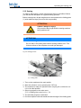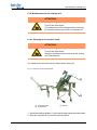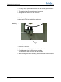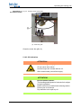
1
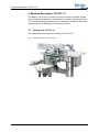
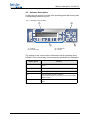
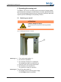
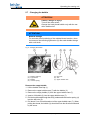
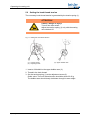
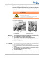
743-221-01 Operating Manual All rights reserved. Property of Dürkopp Adler AG and protected by copyright. Reproduction or publication of the content in any manner, even in extracts, without prior written permission of Dürkopp Adler AG, is prohibited. Copyright © Dürkopp Adler AG - 2013 Table of Contents 1 About this operating manual ..................................................... 3 1.1 1.2 1.3 1.4 1.5 1.5.1 1.5.2 Scope of application of the operating manual............................... 3 For whom is this operating manual?............................................. 3 Conventions of representation – Symbols and characters ........... 3 Other documents .......................................................................... 4 Liability.......................................................................................... 4 Transportation............................................................................... 5 Intended use ................................................................................. 5 2 Performance description ........................................................... 7 2.1 2.2 2.3 2.4 Features........................................................................................ 7 Declaration of conformity .............................................................. 8 Optional equipment....................................................................... 8 Technical data ............................................................................ 10 3 Safety instructions ................................................................... 11 3.1 3.2 Basic safety instructions ............................................................. 11 Signal words and symbols used in warnings .............................. 12 4 Machine description 743-221-01.............................................. 15 4.1 4.2 Sewing unit 743-221-01.............................................................. 15 Software description ................................................................... 16 5 Operating the sewing unit........................................................ 17 5.1 5.2 5.3 5.4 5.5 5.6 5.7 5.7.1 5.8 5.9 5.10 5.11 5.12 5.13 5.14 5.14.1 5.14.2 5.14.3 5.15 5.16 5.16.1 5.16.2 5.16.3 Switching on and off ................................................................... 17 Threading in the needle thread................................................... 18 Adjusting the needle-thread tension ........................................... 19 Needle thread monitor ............................................................... 20 Setting the thread regulator ........................................................ 21 Winding on the hook thread........................................................ 22 Changing the bobbin................................................................... 24 Counter for the hook thread reserve........................................... 25 Residual thread monitor:............................................................. 25 Setting the hook thread tension .................................................. 27 Changing the needle................................................................... 28 Changing the template set.......................................................... 29 Working range, angle and length................................................ 30 Setting the insertion depth of the folding table............................ 32 Setting the control unit ................................................................ 34 Functions in the main menu........................................................ 34 Functions in the submenu........................................................... 36 Error messages .......................................................................... 39 Sewing ........................................................................................ 40 Maintenance of the sewing unit .................................................. 42 Swinging up the machine head................................................... 42 Cleaning...................................................................................... 43 Oil lubrication .............................................................................. 44 6 Installation................................................................................. 47 6.1 Delivery scope ............................................................................ 47 6.2 Installing the sewing unit............................................................. 48 6.2.1 Transportation............................................................................. 48 Operating manual 743-221-01 version 01.0 - 09/2013 1 Table of Contents 6.2.2 6.2.3 6.3 6.3.1 6.3.2 6.3.3 6.4 6.5 6.5.1 6.6 6.7 6.7.1 6.7.2 6.7.3 6.8 2 Removing the transport securing devices................................... 49 Setting the working height .......................................................... 49 Attaching the machine parts removed for shipping..................... 50 Thread reel holder ...................................................................... 50 Holding device for the template set ............................................ 51 Attaching the operating panel OP 3000...................................... 51 Electrical connection................................................................... 52 Pneumatic connection ................................................................ 53 Oil lubrication .............................................................................. 54 Putting into operation.................................................................. 56 Installation of the software .......................................................... 57 General information .................................................................... 57 Loading the program................................................................... 58 Dongle-Update via Internet......................................................... 59 Customer service........................................................................ 59 Operating manual 743-221-01 version 01.0 - 09/2013 About this operating manual 1 About this operating manual The operating manual for the 743-221-01 sewing unit was compiled with the utmost care. It contains information and notes in order to make longterm and reliable operation possible. Should you notice any discrepancies or if you have improvement requests, then we would be glad to receive your feedback, chapter 5.8. Please regard the operating manual as part of the product and keep it in a safe place where it can be easily accessed. Read the operating manual completely prior to using the unit for the first time. Only pass the product on to third parties together with this operating manual. 1.1 Scope of application of the operating manual This operating manual describes the set-up and intended use of the 743221-01 sewing unit. 1.2 For whom is this operating manual? The operating manual is intended for: • Machine operators: This group of employees has been trained in operating the machine and can access the operating manual. Specifically Chapter 5 of the Operating Instructions is important for this group of employees. • Technicians: This group of employees has the appropriate technical training allowing them to perform maintenance on the sewing unit or to repair faults. Specifically Chapter 6 of the Set-up Instructions is important for this specialized staff. Service instructions are supplied separately. With regard to minimum qualification and other requirements to be met by the personnel, please also observe chapter 3 Safety Instructions. 1.3 Conventions of representation – Symbols and characters For an easy and quick understanding different information are depicted or highlighted in this operating manual by the following characters: Operating manual 743-221-01 version 01.0 - 09/2013 3 About this operating manual Symbol/character • Meaning Lists are identified by bullet points. 1. Instructions are numbered and have to be performed in the specified order. 2. References to further information in this operating manual or other documents are identified by this symbol. Safety Important warnings for the user of the machine are specifically marked. Because safety constitutes an area of major importance, hazard symbols, levels of risk, and their signal words are described separately in chapter 3 Safety Instructions. Location informa- Information on where something is positioned using the terms "right" or tion "left" must always be regarded from the operator's point of view if the fig- ure gives no other obvious indication for determining the location. 1.4 Other documents The device contains built-in components from other manufacturers. The respective manufacturers have carried out hazard assessments for these purchased parts and confirmed compliance of the design with the applicable European and national regulations. The intended use of the built-in components is described in the corresponding manuals of the manufacturers. 1.5 Liability All information and notes in this operating manual have been compiled in accordance with the latest technology and the applicable standards and regulations. The manufacturer cannot be held liable for any damage due to: • Damage during transport • Failure to observe the operating manual • Improper use • Unauthorized modifications to the machine • The deployment of untrained personnel • Using spare parts not approved 4 Operating manual 743-221-01 version 01.0 - 09/2013 About this operating manual 1.5.1 Transportation Dürkopp Adler cannot be held liable for any damage during transport. Check the delivered product immediately after receiving it. Report any damage to the last transport manager. This also applies if the packaging is not damaged. Keep the machines, devices and packaging material in the condition they were at the time when the damage was identified. That secures any claims towards the transport company. Report all other complaints to Dürkopp Adler immediately after receiving the product. 1.5.2 Intended use The Beisler 743-221-01 is for sewing light to moderately heavy material. The machine is only intended for processing dry material. The material must not contain any hard objects. The seam is generally sewn with sewing yarns made from textile fibers of these dimensions: up to 40/NeB (cotton thread), 65/2 Nm (synthetic threads) or 65/2 Nm (core threads). If other kinds of threads are to be used, the possible dangers arising from them have to be assessed and, if necessary, safety measures have to be taken. The sewing machine is intended for industrial use. The machine may only be set up and operated in dry conditions on wellmaintained premises. If the machine is operated on premises that are not dry and well-maintained, then further measures may be required which must be compatible with EN 60204-31:1999. Only authorized/trained persons may work on the machine. The manufacturer will not be held liable for damage resulting from improper use. WARNING Danger due to high voltage, crushing and sharp objects. Improper use can result in injuries. Please follow all instructions in the manual. ATTENTION Improper use could result in material damage. Please follow all instructions in the manual. Operating manual 743-221-01 version 01.0 - 09/2013 5 About this operating manual 6 Operating manual 743-221-01 version 01.0 - 09/2013 Performance description 2 Performance description The Beisler 743-221-01 is a sewing unit for the sewing of single pointed darts and pleats of straight or curved shape in trousers, skirts and the like. The sewing unit is equipped with a double lockstitch sewing machine class 935-271-710 with large horizontal hook, needle thread monitor and residual thread monitor for the hook thread. 2.1 Features • Sewing length controlled alternatively by light barrier or by programming • Seam protection alternatively at seam beginning and seam end through stitch condensing or bartacking the material and thread chain • Thread trimming system: Controlled chain trimmer • High sewing performance and short cycle duration due to DAC classic in combination with a stepping motor and an additional control unit for the material feed • Fully overlapping working method • Compact, height adjustable sewing unit with transport coasters, to be operated in standing or sitting position • Positioning station, folder station and sewing station are combined in a single swivel-mounted unit for easy maintenance and setting access • Electronic thread monitoring system • Designed to process spun and monofilament threads • Integrated setting disc with positioning marks on the hand-wheel for a rapid and precise control of the machine settings • A template set adapted to the sewing shape retains and guides the workpiece • The template can be easily exchanged; upon ordering the sewing unit, one or several template sets have to be selected. • The dart depth depends on its length, the template set and the setting of the folding table; by adjusting the folding table between 0 and 10°, the dart depth can be altered Operating manual 743-221-01 version 01.0 - 09/2013 7 Performance description 2.2 Declaration of conformity The machine complies with the European regulations specified in the declaration of conformity or in the installation declaration. 2.3 Optional equipment By means of a flexible system of optional equipment the sewing unit can be equipped optimally and economically corresponding to the respective application. = Basic equipment = required equipment, alternatively = Optional equipment Order No. Subclass 743-221-01 Basic equipment 1970 991221 Sewing unit 743-221-01 0791 743506 Accessories Required equipment, to be selected one template set and one folding table is required 0793 078001 or 0793 078002 or 0793 078034 or 079 078091 Template set, straight dart or Template set, curved dart or Template set, pleats or Template set, dart or pleats customized, special design 0792 038504 or 0792 038506 or 0783 080000 Folding table for darts or Folding table for pleats or Vacuum table for darts Working method workpiece take-up from the front bundle clamp, positioning table and smoother Racks 0794 013631 8 Operating manual 743-221-01 version 01.0 - 09/2013 Performance description 0794 013731 Working method workpiece take-up from the left bundle clamp, positioning table and smoother 0794 013333 Blower pipe from the top and the right 0794 013444 Positioning table when using in-house bundle clamp carriage 0797 003031 Pneumatic connection kit Operating manual 743-221-01 version 01.0 - 09/2013 9 Performance description 2.4 Technical data Technical data 743-221-01 Sewing stitch type 301/double lockstitch Number of needles 1 Needle system 134 serv 7 Needle size [Nm] 90 Max. number of stitches (programmable) [min-1] 4800 Stitch length (programmable) [mm] 0.5-3 Stitch condensing (programmable) [mm] Number of stitches [n] (programmable) 1-10 Number of bartack stitches [n] (programmable) 0-5 Max. stitch length [mm] 150 Max. seam offset [mm] +/- 13 Operating pressure [bar] 6 Air consumption per working cycle (7 sec.) ca. [NL] with blower stimulus 2 12 Table height (infinitely variable) [mm] - min - max Length, width, height [mm] Weight [kg] Nominal voltage [V] Frequency [Hz] 10 0.5-2.0 850 1250 2300, 1200, 1350 about 130 1 x 190-240 50/60 Operating manual 743-221-01 version 01.0 - 09/2013 Safety instructions 3 Safety instructions This section contains basic instructions for your safety. Read the instructions carefully before setting up or operating the machine. Make sure to follow the information included in the safety instructions. Failure to do this can result in serious injury and in damage to the machine. 3.1 Basic safety instructions The machine may only be used as described in this operating manual. The operating manual must be available at the machine's location at all times. Work on live components and equipment is prohibited. Exceptions are defined in the specifications in DIN VDE 0105. For the following work, the machine must be disconnected from the power supply using the main switch or by disconnecting the power plug: • Replacing the needle or other sewing tools • Leaving the workplace • Performing maintenance work and repairs Missing or faulty spare parts could impair safety and damage the machine. Therefore only use original spare parts from the manufacturer. Transportation When the machine is being transported, use a lifting carriage or a forklift. Raise the machine max. 20 mm and secure it against slipping off. Set-up The connecting cable must have a power plug approved in the specific country. The power plug may only be connected to the power cable by a qualified specialist. Operator's obliga- Observe the country specific safety and accident prevention regulations tions and the legal regulations concerning industrial safety and the protection of the environment. All warnings and safety signs on the machine must always be in legible condition and may not be removed. Missing or damaged labels must be replaced immediately. Requirements to The machine may only be set up by qualified specialists. be met by the personnel Maintenance work and repairs may only be carried out by qualified specialists. Operating manual 743-221-01 version 01.0 - 09/2013 11 Safety instructions Work on electrical equipment may only be carried out by qualified specialists. Only authorized persons may work on the machine. Every person who works on the machine must have read the operating manual first. Operation Inspect the machine while in use for any externally visible damage. Inter- rupt your work if you notice that the machine has been altered. Report any alterations to your supervisor. A damaged machine must not be operated any more. Safety equipment Safety equipment must not be removed or put out of service. If this cannot be avoided for a repair operation, the safety equipment has to be refitted and put back into service immediately afterwards. 3.2 Signal words and symbols used in warnings Warnings in the text are distinguished by color bars. The color scheme reflects the severity of the danger. Signal words specify the severity of a danger: Signal words Signal words and the endangerment that they describe: Signal word DANGER Resulting in death or serious injury. WARNING Death or serious injury possible. CAUTION Minor to moderate injuries possible. ATTENTION 12 Endangerment Material damage possible. Operating manual 743-221-01 version 01.0 - 09/2013 Safety instructions Symbols In the case of dangers to personnel, the following symbols indicate the type of hazard: Symbol Type of danger General danger Danger due to electric shock Danger due to sharp objects Danger due to crushing Examples Examples of the layout of the warnings in the text: DANGER Type and source of the danger Consequences in the event of noncompliance Measures for avoiding the danger This is what a warning looks like for a hazard that will result in serious injury or even death if not com- WARNING Type and source of the danger Consequences in the event of noncompliance Measures for avoiding the danger This is what a warning looks like for a hazard that could result in serious injury or even death if not complied with. Operating manual 743-221-01 version 01.0 - 09/2013 13 Safety instructions CAUTION Type and source of the danger Consequences in the event of noncompliance Measures for avoiding the danger This is what a warning looks like for a hazard that could result in moderate or minor injury if the warning is not complied with. CAUTION Type and source of the danger Measures for avoiding the danger This is what a warning looks like for a hazard that could result in environmental damage if not complied with. ATTENTION Type and source of the danger Measures for avoiding the danger This is what a warning looks like for a hazard that could result in material damage if not complied with. 14 Operating manual 743-221-01 version 01.0 - 09/2013 Machine description 743-221-01 4 Machine description 743-221-01 The Beisler 743-221-01 is a sewing unit for the sewing of single pointed darts and pleats of straight or curved shape in trousers, skirts and the like. The correct operating principle involves a sequence of different steps and requires precise knowledge of all operating controls. 4.1 Sewing unit 743-221-01 The illustration below shows the sewing unit 743-221-01. Fig. 1: General overview of the 743-221-01 Operating manual 743-221-01 version 01.0 - 09/2013 15 Machine description 743-221-01 4.2 Software description At this point only a short overview of the operating panel with its keys and corresponding functions is given. Fig. 2: Operating Panel OP 3000 ཱི ི ཱ (1) - Display (2) - Numeric keys (3) - Escape key (4) - OK key The settings of the control unit are effectuated via the operating panel OP3000. Here is a summary of some important possibilities for navigation: Key/key group 16 Function 1 to 6 Switching on and off the functions shown in the display above. Arrow keys (◄,►) Navigating in the main menu Arrow keys (▲,▼) Increasing or decreasing values/parameters OK Short keystroke confirms a selection Long keystroke resets f.e. the piece counter or the bobbin thread counter ESC No function in the main menu, but relevant in the submenu Operating manual 743-221-01 version 01.0 - 09/2013 Operating the sewing unit 5 Operating the sewing unit The Beisler 743-221-01 is a sewing unit for the sewing of single pointed darts and pleats of straight or curved shape in trousers, skirts and the like. The correct operating principle involves a sequence of different steps and requires precise knowledge of all operating controls. 5.1 Switching on and off ATTENTION! Caution: Danger of injury! Do not reach into the area of moving machine parts. Fig. 3: Switching the machine on and off (1) - Main switch Switching on 1. Turn on the main switch (1). The control is initialized. The message “Reference” is displayed: The sewing unit calls for a reference run. 2. Press the “OK” key on the control panel. The reference run is carried out. The machine is ready for operation. Switching off Turn off the main switch (1). The sewing unit is cut off the power supply. It is no longer ready for operation. Operating manual 743-221-01 version 01.0 - 09/2013 17 Operating the sewing unit 5.2 Threading in the needle thread ATTENTION! Caution: Danger of injury! Turn off the main switch. Thread the needle thread only with the sewing unit switched off. Fig. 4: Threading in the needle thread Thread the needle thread as shown in the picture above. 18 Operating manual 743-221-01 version 01.0 - 09/2013 Operating the sewing unit 5.3 Adjusting the needle-thread tension Fig. 5: Adjusting the needle thread tension (1) - Main tensioner Main tension The main tensioner (1) should generate the adequate needle thread tension for the particular material and needle thread • Turn the knurled nut accordingly. Turn the knurled nut in clockwise direction = Increase the tension Turn the knurled nut in counter-clockwise direction = Decrease the tension Operating manual 743-221-01 version 01.0 - 09/2013 19 Operating the sewing unit 5.4 Needle thread monitor ATTENTION! Caution: Danger of injury! Turn off the main switch before threading in the needle. A restart is only possible after switching the main switch off and on again. Fig. 6: Needle thread monitor (1) - Thread monitor At needle thread rupture, a rupture message will appear on the display and the machine stops. 1. Turn the machine off the main switch. 2. Remove the unfinished workpiece. 3. Thread in the thread again, 5.2 Threading in the needle thread, p. 18. 4. Turn on the machine at the main switch. 5. Start a new sewing cycle. 20 Operating manual 743-221-01 version 01.0 - 09/2013 Operating the sewing unit 5.5 Setting the thread regulator ATTENTION! Caution: Danger of injury! Turn off the main switch. Adjust the thread regulator only with the sewing unit switched off. The thread regulator (2) controls the quantity of thread required for the stitch formation. The thread regulator has to be precisely adjusted for an optimum sewing result. The setting of the thread regulator depends on the following factors: • Stitch length • Thickness of the material • Characteristics of the yarn utilized With correct setting the needle-thread loop (6) should slide without any overrun and with low tension over the thickest point of the hook. Fig. 7: Setting the thread regulator ཱ ཱ ཱིི ུ (1) - Thread take-up spring (2) - Thread regulator (3) - Wire ཱུ (4) - Scale (5) - Screw (6) - Needle thread loop How to adjust the thread regulator: 1. Loosen screw (5). 2. Set the thread regulator (2). The vertical wire (3) serves in conjunction with the scale (4) as adjusting aid (guide value: 2.5). 3. Tighten screw (5). Operating manual 743-221-01 version 01.0 - 09/2013 21 Operating the sewing unit Adjustment instruction: The thread regulator's (2) is correctly adjusted if: The thread take-up spring (1) is pulled down about 1 mm from its upper final position, when the thread loop (6) passes the maximum hook breadth. The length of 1 mm is an approximative guide value. Depending on the tension of the thread take-up spring it may be higher or lower. 5.6 Winding on the hook thread ATTENTION! Caution: Danger of injury! Turn off the main switch. Thread the hook thread for winding only with the sewing unit switched off. Fig. 8: Winding on the hook thread ཱ (1) - Bobbin thread tension (2) - Winder shaft ི ཱི (3) - Trimming clamp (4) - Winder clip 1. For a trouble-free functioning of the residual thread monitor always remove any thread waste from the bobbin hub before winding. 2. Thread the hook thread according to the picture. 3. Prewind the hook thread in clockwise direction into the reserve groove of the bobbin hub. 4. Fit the bobbin on the winder shaft (2). 5. Pull the thread end through the trimming clamp (3) and cut it off. 22 Operating manual 743-221-01 version 01.0 - 09/2013 Operating the sewing unit 6. Swivel the winder clip (4) against the bobbin. 7. Set the bobbin thread tension (1). Wind on the hook thread with minimum tension. 8. Turn the main switch on. 9. Start the sewing process. After reaching the set bobbin filling level the winder stops automatically. For the setting of the bobbin filling level, see Service Instructions. Operating manual 743-221-01 version 01.0 - 09/2013 23 Operating the sewing unit 5.7 Changing the bobbin ATTENTION! Caution: Danger of injury! Turn off the main switch. Change the hook thread bobbin only with the machine switched off. ATTENTION! Material damage For a trouble-free functioning of the residual thread monitor, clean the lenses of the reflecting light barrier (2) after each bobbin change with a soft cloth. Fig. 9: Changing the bobbin ཱ ི ཱི ུ ཱུ (1) - Bobbin case flap (2) - Light barrier (3) - Bobbin (4) - Tension spring ྲྀ (5) - Drill-hole (6) - Slot (7) - Upper bobbin case Remove the empty bobbin. 1. Lift the bobbin case flap (1). 2. Remove the upper bobbin case (7) with the bobbin (3). 3. Remove the empty bobbin (3) from the upper bobbin case (7). 4. Insert a full bobbin (3) into the upper bobbin case (7). 5. Pull the hook thread through the slit (6) underneath the tension spring (4) into the drill-hole (5). 6. Pull about 5 cm of hook thread out of the upper bobbin case (7). When pulling the thread, the bobbin (3) should turn into the direction indicated by the arrow. 24 Operating manual 743-221-01 version 01.0 - 09/2013 Operating the sewing unit 7. Insert the upper bobbin case (7) back into the hook, make sure the bobbin case flap (1) snaps into place. 8. Turn on the main switch. 9. Start a new sewing cycle. 5.7.1 Counter for the hook thread reserve The remaining number of hook thread stitches is indicated on the display, see 5.14 Setting the control unit, p. 34. Resetting 1. Select the symbol hook thread counter with the arrow keys. 2. Effectuate a long stroke on the “OK” key. The counter is reset to its initial values. How to set the initial value indicated by the hook thread counter is described in the Service Instructions. 5.8 Residual thread monitor: The residual thread monitor controls the thread reserve on the hook thread bobbin via reflecting infrared light barrier (1). Fig. 10: Function Residual thread monitor (1) - Light barrier (2) - Reflecting surface ཱ ི (3) - Bobbin hub Function After a certain number of seams the hook thread quantity on the bobbin is used up. Operating manual 743-221-01 version 01.0 - 09/2013 25 Operating the sewing unit The light beam transmitted by the light barrier (1) is reflected by the exposed reflecting surface (2) of the bobbin hub (3). The display of the control unit shows a corresponding message. The seam is safely finished with the thread remaining in the reserve groove. ATTENTION! Caution: Danger of injury! Turn off the main switch. Change the hook thread bobbin only with the machine switched off. Changing the bobbin 1. Turn off the main switch. 2. Change the bobbin Clean the lenses of the light barrier with a soft cloth after every bobbin change. 3. Turn the main switch on. 4. Start a new sewing cycle. 26 Operating manual 743-221-01 version 01.0 - 09/2013 Operating the sewing unit 5.9 Setting the hook thread tension The necessary hook thread tension is generated by the tension spring (1). ATTENTION! Caution: Danger of injury! Turn off the main switch. Adjust the tension spring (1) only with the sewing unit switched off. Fig. 11: Setting the hook thread tension ཱ ི (1) - Tension spring (2) - Adjusting screw ི (3) - Upper bobbin case 1. Insert a full bobbin in the upper bobbin case (3). 2. Thread in the hook thread. 3. Set the tension spring (1) at the adjustment screw (2). Guide value: The hook thread tension should be about 20-30 g. The bobbin case should slowly sink down through its own weight. Operating manual 743-221-01 version 01.0 - 09/2013 27 Operating the sewing unit 5.10 Changing the needle ATTENTION! Caution: Danger of injury! Turn off the main switch. The needle may only be changed with the sewing machine switched off. Fig. 12: Changing the needle ཱ ི (1) - Screw (2) - Needle bar (3) - Groove 1. Loosen screw (1) and remove the needle. 2. Push the new needle into the drill-hole of the needle holder (2) as far as it will go. Attention! Seen from the machine operator's side the needle scarf (3) should point to the right, i. e. to the hook tip (see sketch). 3. Tighten screw (1). ATTENTION! Material damage When changing to another needle size, the distance between hook and needle has to be readjusted, Service Instructions). Ignoring the above mentioned correction can cause the following errors: Changing to a smaller needle size: • Missed stitches • Thread damage Changing to a bigger needle size: • Damage on the hook tip. • Damage on the needle 28 Operating manual 743-221-01 version 01.0 - 09/2013 Operating the sewing unit 5.11 Changing the template set A template set adapted to the desired sewing shape has to be inserted. It allows for the sewing of straight and curved darts, pleats or, on request, also special customer requirements can be realized, 2.3 Optional equipment, p. 8. ATTENTION! Caution: Danger of injury! Turn off the main switch. The template set may only be changed with the sewing machine being switched off. Fig. 13: Changing the template set ཱ (1) - Handle (2) - Template set ི ཱི (3) - Control cam (4) - Hold-down cylinder Removing 1. Turn the hand wheel until the needle stands in the 2nd position (UDC). the template set 2. Slide the template set (2) into the left end position. 3. Turn the handle (1) about 90° in counter-clockwise direction. 4. Lift the template set (2) at the left side and carefully detach it from the transport carriage. 5. Remove the template set. Inserting 1. Turn the hand wheel until the needle stands in the 2nd position (UDC). the template set 2. Move the transport carriage to the left end position. 3. Bear the template set (2) with the right side carefully onto the transport carriage. 4. Turn the handle (1) 90° in counter-clockwise direction and lay the template set completely onto the transport carriage. 5. Turn back the handle (1). The template set is locked and safely fastened to the transport carriage. Operating manual 743-221-01 version 01.0 - 09/2013 29 Operating the sewing unit 6. Position the hold-down cylinder (4) with the guide roller on the control cam (3). 7. Slide the template set to the right as far as it will go. 5.12 Working range, angle and length The dart depth depends on: • the individual template set • the dart length • the position of the folding table The folding table can be continuously adjusted from 0-10°. The dart depths for different inclinations and lengths are indicated in the diagrams. The curve for the curved darts template set is also indicated. ATTENTION! Caution: Danger of injury! Turn off the main switch. Set the inclination only with the sewing machine switched off Fig. 14: Setting the inclination ཱ (1) - Scale (2) - Handle Setting the inclination 1. Retract the folding table 2. Press the handle (2) together and adjust the folding table according to the scale (1). 3. Release the handle. 30 Operating manual 743-221-01 version 01.0 - 09/2013 Operating the sewing unit The angle is set. 4. Pull out the folding table. . Setting the length Maximum dart length 150 mm. The seam length is regulated by programming it in the main menu or by the light barrier. The variant to be used, light barrier or set value, can be selected in the main menu, 5.14 Setting the control unit, p. 34. With transparent sewing material it is recommended to regulate the seam length by programming. Example Template set, straight darts Fig. 15: Working range for darts (1) - Dart depth max. 2.1 cm at 10°, length 9.5 cm (2) - Dart depth max. 0.4 cm at 0°, length 8.5 cm (3) - Template set, straight darts (4) - Template set, curved darts Example Template set pleats Fig. 16: Working range for pleats (1) - Pleat depth max. 3.2 cm at 5°, length 5 cm (2) - Pleat depth max. 2.5 cm at 0°, length 6 cm (3) - Template set for pleats Operating manual 743-221-01 version 01.0 - 09/2013 31 Operating the sewing unit 5.13 Setting the insertion depth of the folding table ATTENTION! Caution: Danger of injury! Turn off the main switch. The insertion depth may only be set or altered with the sewing machine being switched off. The first needle entry in the material should be as close as possible to the fold edge. In order to achieve an evenly slim dart point with material of varied thickness, the machine is equipped with a fine adjustment. Up to 7 different insertion depths can be set by using the stops (4). Fig. 17: Setting the insertion depth ཱི ཱ ི (1) - Stop (2) - Adjustment knob (3) - Set screw (4) - Lever Setting the insertion depth 1. Release the lever (4). 2. Slide the folding table on its guiding a little to the front. 3. Set one of the set screws (3) (7 pieces) to the desired insertion depth. 4. Turn the adjustment knob (2) to the desired insertion depth (until it stops). 5. Slide the folding table back to the rear. The adjustment knob (3) has to abut on the stop (1). 6. Tighten the lever (4) again. 32 Operating manual 743-221-01 version 01.0 - 09/2013 Operating the sewing unit Altering the insertion depth 1. Release the lever (4). 2. Slide the folding table on its guiding a little to the front. 3. Turn the adjustment knob (2) to the desired insertion depth (until it stops). 4. Slide the folding table back to the rear. The adjustment knob (3) has to abut on the stop (1). 5. Tighten the lever (4) again. Operating manual 743-221-01 version 01.0 - 09/2013 33 Operating the sewing unit 5.14 Setting the control unit At this point only the settings needed for sewing will be mentioned. Additional settings on the technician level are described in the Service Instructions. The control unit is operated via the operating panel OP3000, 4.2 Software description, p. 16. After switching on the machine the firmware and software versions will briefly be displayed. After this start the reference run by pressing the “OK“ key, p. 17. After the reference run the main menu is displayed. 5.14.1 Functions in the main menu Fig. 18: Main menu ཱ ི ཱི ུ ཱུ ྲྀ (5) - Seam counter (6) - Submenu (7) - Switching additional functions on/off (1) - Program selection (2) - Seam length (3) - Stitch length (4) - hook thread counter Main menu - Top line • Select the desired parameter with the arrow keys (◄,►). The activated parameter is highlighted. • Enter the desired value by using the arrow keys (▼,▲). The value is directly applied and memorized for the particular program. Program selection Program number entry Range of values: 1 - 20 Seam length Seam length entry in mm Range of values: 19 - 150 Important: The seam length can only be entered if the light barrier ( p. 35) is disabled. Stitch length Stitch length entry in mm Range of values: 0.5 - 3.0 34 Operating manual 743-221-01 version 01.0 - 09/2013 Operating the sewing unit Main menu - Top line Hook thread counter Display of the number of stitches (in intervals of 10 stitches) that can still be sewn with the bobbin. Resetting the hook thread counter: • Long stroke on the “OK” key Seam counter Display of the seam segments that have been sewn so far Resetting the seam counter: • Long stroke on the “OK” key Submenu Access to the submenu with the “OK” key Main menu - Bottom line In the bottom line additional functions are activated or disabled. • Press the numerical key below the symbol of the desired function. You can switch between “activated” and “disabled”. When the function is disabled the symbol is crossed out. The setting is directly applied and memorized for the particular program. Light barrier Switch the light barrier on or off with the numerical key “1”. Important: If the light barrier is activated, the program will automatically stop the seam upon reaching the bottom edge of the fabric. Disable the function for the manual setting of the seam length ( p. 34). Seam beginning Switch the tack or the stitch condensing at the seam beginning on or off with the numerical key “2”. Seam midsection Switch the tack or the stitch condensing at the seam midsection on or off with the numerical key “3”. Seam end Switch the tack or the stitch condensing at the seam end on or off with the numerical key “4”. Smoother Switch the smoother on or off with the numerical key “5”. Blow-out device Switch the blow-out device on or off with the numerical key “6”. Operating manual 743-221-01 version 01.0 - 09/2013 35 Operating the sewing unit 5.14.2 Functions in the submenu Submenu structure Symbol Menu item Settings Speed Soft Start Activated, Stitches, Speed Advance Length, Speed Seam Begin Lock type, Stitches, Speed, Stitchlength Seam Between Lock type, Stitches, Speed, Stitchlength, Start at Seam End Lock type, Stitches, Speed, Stitchlength Thread Chain Length, Speed Stacker TimeTillStart, TimeTillStop Navigating in the submenu Fig. 19: Setting in the submenu ཱ (1) - Symbol for the menu item (2) - Symbol for the setting ི (3) - Selected entry: highlighted Selecting the menu 1. Select the desired menu item by using the arrow keys (▼,▲). item The menu item is highlighted. 2. Activate the menu item with the “OK” key. The symbol for the menu item (1) appears on the left side of the display. On the right side the settings of the menu item are listed. Selecting the set- 3. Select the desired setting by using the arrow keys (▼,▲). ting The setting is highlighted (3). 4. Activate the setting with the “OK” key. In addition to the symbol for the menu item (1), the symbol for the setting (2) appears on the left side of the display. 36 Operating manual 743-221-01 version 01.0 - 09/2013 Operating the sewing unit Changing the val- 5. Change the value for the setting by using the numerical keys or the ue arrow keys (▼,▲). 6. Confirm the desired value with the “OK” key. The value is applied and memorized for the particular program. Return 7. Use the arrow key ◄ to return to the previous level in the submenu. 8. Use the escape key to return to the main menu. Settings in the submenu Menu item Speed Number of revs for the sewing speed Symbol Explanation Range of values There are no further settings for this menu item. Directly enter the value for the speed. 500 – 4000 Menu item Soft start Settings for the soft start at seam beginning Symbol Setting Explanation Range of values Activated Switch the soft start on or off with the “OK” key. • On: display shows ““ • Off: blank display On/Off Stitches Number of stitches for the soft start 1–9 Speed Number of revs for the sewing speed at soft start 500 – 2000 Menu item Advance Settings for the advance at seam beginning Symbol Setting Explanation Range of values Length Length of the advance in mm 0 – 50 Speed Number of revs for the sewing speed at advance 500 –0 4800 Operating manual 743-221-01 version 01.0 - 09/2013 37 Operating the sewing unit Menu item Seam Begin Settings for tacks/stitch condensing at seam beginning Symbol Setting Explanation Range of values Lock Type Choose between tack and stitch condensing with the “OK” key: • Tack: display shows ““ • Stitch condensing: blank display Tack/ stitch condensing Stitches Number of stitches with tack/stitch condensing 1–9 Speed Number of revs for the sewing speed when sewing the tack/stitch condensing 500 – 3000 Stitchlength Stitch length of the stitch condensing in mm 0.5 – 2.0 Menu item Seam Between Settings for tacks/stitch condensing at seam midsection Symbol Setting Explanation Range of values Lock Type Choose between tack and stitch condensing with the “OK” key: • Tack: display shows ““ • Stitch condensing: blank display Tack/ stitch condensing Stitches Number of stitches with tack/stitch condensing 1–9 Speed Number of revs for the sewing speed when sewing the tack/stitch condensing 500 – 3000 Stitchlength Stitch length of the stitch condensing in mm 0.5 – 2.0 Start at Indicates the seam segment in mm, after which the tack/stitch condensing will start. 10 – 130 Menu item Seam End Settings for the tack/stitch condensing at seam end Symbol 38 Setting Explanation Range of values Lock Type Choose between tack and stitch condensing with the “OK” key: • Tack: display shows ““ • Stitch condensing: blank display Tack/ stitch condensing Stitches Number of stitches with tack/stitch condensing 1–9 Speed Number of revs for the sewing speed when sewing the tack/stitch condensing 500 – 3000 Stitchlength Stitch length of the stitch condensing in mm 0.5 – 2.0 Operating manual 743-221-01 version 01.0 - 09/2013 Operating the sewing unit Menu item Thread Chain Settings for a thread chain at seam end Symbol Setting Explanation Range of values Length Length of the thread chain in mm 8 – 25 Speed Number of revs for the sewing speed when sewing the thread chain 500 – 3000 Menu item Stacker Settings for the stacker Symbol Setting Explanation Range of values TimeTillStart Time span in milliseconds after the seam end, before the smoother is activated. 10 –1000 TimeTillStop Time span in milliseconds from the activation of the smoother until the shackle of the smoother moves upwards again. 10 –1000 5.14.3 Error messages After certain incidents like f. e. a thread rupture the sewing process has to be interrupted. An error number will appear on the display. The following table lists the error numbers and their explanation as well as the troubleshooting. Number Meaning Troubleshooting 3210 Needle thread rupture Thread in a new needle thread, p. 18. 3215 Hook thread counter has reached value 0 Check the bobbin's thread reserve and insert a new bobbin if necessary, p. 24 reset the hook thread counter, p. 35 3216 Residual thread monitor reports empty bobbin Insert a new bobbin, p. 24. 3302 No pressure available Check the pressure at the maintenance unit, p. 53. 3303 Folding table in wrong position Pull out the folding table. 3304 No template set inserted Insert a template set. Check the contact pressure, if a template set is already inserted. 3340 Contact pressure too low Correct the contact pressure for the template set by setting the screw at the top on the hold-down cylinder. Operating manual 743-221-01 version 01.0 - 09/2013 39 Operating the sewing unit 5.15 Sewing In order to start sewing, certain requirements have to be fulfilled. Below you will find the description of a typical sewing process. Before sewing start, all dart lengths have to be marked on the folding plate (1) with adhesive tape (flat and as thin as possible). ATTENTION! Caution: Danger of injury! Only mark the dart length with the sewing machine being switched off. ATTENTION! Material damage Do not slide in the folding table without sewing material on it. The friction surfaces of the template set could get damaged. Fig. 20: Sewing process (1) - Folding plate 1. Turn on the machine at the main switch. 2. Start the reference run by pressing the “OK” key. The machine is ready for operation after carrying out a reference run. It is in its initial position. 3. Select a program in the main menu, 5.14 Setting the control unit, p. 34. The selected program is activated. 4. Put the workpiece with both hands around the edge of the folding plate. 40 Operating manual 743-221-01 version 01.0 - 09/2013 Operating the sewing unit 5. Align the cut edges with the right hand to come on top of each other. 6. Adjust the notch for the dart length exactly at the rear edge of the folding plate. 7. Fix the workpiece by holding it with the right hand and slide in the folding plate. The workpiece is kept in place by the template set. The folding plate slides back. The sewing process is carried out. Operating manual 743-221-01 version 01.0 - 09/2013 41 Operating the sewing unit 5.16 Maintenance of the sewing unit ATTENTION! Caution: Danger of injury! Turn off the main switch. The maintenance of the sewing machine must only be carried out when the machine is switched off. 5.16.1 Swinging up the machine head. ATTENTION! Caution: Danger of injury! Turn off the main switch. Swing the machine head up only when the sewing unit is switched off. For maintenance work the machine head can be swung up. Fig. 21: Swinging up the machine head ི ཱ (1) - Positioning table (2) - Template set (3) - Handle 1. Swivel the positioning table (1), the bundle clamp and the smoother aside 2. Slide the template set (2) into the left end position. 42 Operating manual 743-221-01 version 01.0 - 09/2013 Operating the sewing unit 3. Carefully swing up the machine head with the handle (3) and make it rest against the support. The machine's gravity center keeps it in position. 4. Swing back the machine in the same way. 5.16.2 Cleaning A clean sewing unit is a trouble-free sewing unit. Daily Fig. 22: Daily cleaning Cleaning (1) - Drain screw 1. Remove all fluff balls. 2. Clean the lenses of the light barrier with a soft cloth. 3. Check the water level in the pressure regulator. The water level must not reach the filter element. 4. After screwing in the drain screw (1) blow out the water under pressure. Operating manual 743-221-01 version 01.0 - 09/2013 43 Operating the sewing unit Depending on Fig. 23: Cleaning as the need arises the amount of fluff ཱ (2) - Motor fan grille Clean the motor fan grille (2). 5.16.3 Oil lubrication ATTENTION! Caution: Danger of injury! Oil can cause skin rashes. Avoid a longer skin contact with the oil. After contact wash yourself thoroughly. ATTENTION! Environmental hazards: The handling and disposal of mineral oils is subject to legal regulations. Deliver used oil to an authorized collecting station. Protect your environment. Pay attention not to spill any oil. 44 Operating manual 743-221-01 version 01.0 - 09/2013 Operating the sewing unit To lubricate the sewing unit use only DA -10 lubricating oil or an equivalent oil with the following specifications: Viscosity at 40° C:10 mm²/s Ignition point:150° C DA-10 lubricating oil is available from the DÜRKOPP ADLER AG sales offices under the following parts numbers: 250-ml container: 9047 000011 1-liter container 9047 000012 2-liter container 9047 000013 5-liter container 9047 000014 hook lubrication 1. Swinging up the machine head as described. 2. Fill up the oil reservoir (1) with oil up to the marking max. The necessary oil quantity is factory set by the manufacturer. Increase or decrease the oil quantity only in exceptional circumstances. Fig. 24: Oil reservoir 1 - hook lubrication (1) - Oil reservoir 1 Operating manual 743-221-01 version 01.0 - 09/2013 45 Operating the sewing unit Machine head lubrication 1. The oil level in the oil reservoir (2) must not drop below the marking min. 2. If necessary, fill in oil through the drill-hole (1) in the inspection glass up to the marking max. Fig. 25: Oil reservoir 2 - machine head ཱ (1) - Drill-holes 46 (2) - Oil reservoir 2 Operating manual 743-221-01 version 01.0 - 09/2013 Installation 6 Installation In the following, the steps are listed in chronological order. The structure of the chapter follows this order. The manufacturer will not be held liable for damage resulting from improper use. WARNING Danger of injury due to insufficient technical knowledge During the installation of the machine, insufficient technical knowledge can lead to serious injuries. The machine should be installed ONLY by trained personnel. DANGER Risk of injury due to electric power! Unprotected contact with electric power can cause dangerous injuries to life and limb. All work on the electrical equipment may ONLY be carried out by qualified electricians or other appropriately trained persons. ALWAYS disconnect the power plug before carrying out work at the electrical equipment. 6.1 Delivery scope What items are supplied depends on your order. Prior to set-up, please check that all required parts are present. • Standard equipment • Optional equipment • Small parts in the accessories Operating manual 743-221-01 version 01.0 - 09/2013 47 Installation 6.2 Installing the sewing unit 6.2.1 Transportation . CAUTION Risk of injury due to incorrect transportation! Do NOT lift the sewing unit at the table tops. ALWAYS use an elevating platform truck or a forklift CAUTION Risk of injury due to unstable footing! Before putting the sewing unit into operation screw in the castors until the unit attains a secure standing. Lifting the sewing unit • Only with an elevating platform truck or a forklift. For in-house transport the stand is equipped with four castors. Rolling the sewing unit Fig. 26: Transport on castors ཱི ཱ ི (1) - Adjusting screw (2) - Adjusting screw (3) - Adjusting screw (4) - Adjusting screw 1. In order to transport the unit on its castors, turn the setting screws (1) to (4) counter-clockwise. The feet must have sufficient ground clearance for transportation. 2. Transporting the sewing unit 3. To lower the sewing unit turn the setting screws (1) to (4) in clockwise direction. The feet must stand firmly on the ground. 48 Operating manual 743-221-01 version 01.0 - 09/2013 Installation 6.2.2 Removing the transport securing devices Before installing the sewing unit, you have to remove all the securing devices. All movable parts have to be unlocked: • Positioning table • Sewing drive • Smoother and bundle clamp • Positioning table If the sewing unit has to be transported to another place, you have to attach the securing devices again. 6.2.3 Setting the working height The working height is adjustable between 850 and 1250 mm (measured to the upper edge of the table plate). CAUTION Be careful when loosening the attachment screws. The sewing unit may keel over when the tubular feet of the frame are pulled out. Fig. 27: Setting the working height ཱི ཱ ི (1) - Screw (2) - Screw (3) - Screw (4) - Screw 1. Loosen screws (1) to (4). 2. Set the unit to the desired height and level it out. 3. Re-tighten screws (1) to (4) again. Operating manual 743-221-01 version 01.0 - 09/2013 49 Installation 6.3 Attaching the machine parts removed for shipping Some parts of the machine had to be removed or shifted in their position for shipment. These parts have to be attached correctly before start of work. 6.3.1 Thread reel holder The thread reel holder is loosely added for shipment. In order to connect the machine to the power supply from the top, the connection cable can be run through the tube (2) of the thread reel holder. Guide the compressed air supply pipe upwards through the second bore hole in the table top and then attach it to the thread reel holder with cable ties. Fig. 28: Attaching the thread reel holder ཱ ི ཱི (1) - Unwinding bracket (2) - Thread reel holder (3) - Reel plate (4) - Nut 1. Insert the thread reel holder (2) into the bore hole of the table top. 2. Fix it with nut (4) underneath the table top. 3. Align the reel plate (3) and the unwinding brackets (1) parallel to the rear table edge. Reel plate (3) and the unwinding brackets (1) have to point into the same direction. 50 Operating manual 743-221-01 version 01.0 - 09/2013 Installation 6.3.2 Holding device for the template set Fig. 29: Holding device ཱ (1) - Holding device (2) - Template set During the transport the holding device (1) for the template set (2) is underneath the table top. 1. Remove the fastening screws. 2. Rotate the holding (1) device by 180°. 3. Attach the fastening screws again. 6.3.3 Attaching the operating panel OP 3000 Fig. 30: Fixation operating panel OP 3000 ཱ (1) - Control panel (2) - Angle 1. Attach angle (2). 2. Attach the operating panel (1) onto angle (2). Operating manual 743-221-01 version 01.0 - 09/2013 51 Installation 6.4 Electrical connection DANGER Risk of injury due to electric power! Unprotected contact with electric power can cause dangerous injuries to life and limb. All work on the electrical equipment may ONLY be carried out by qualified electricians or other appropriately trained persons. ALWAYS disconnect the power plug before carrying out work at the electrical equipment. Connection Fig. 31: Connection control panel the control panel ཱ (1) - Plug (2) - Screws 1. Carefully insert plug (1) into the rear panel of the operating panel. 2. Tighten the screws (2) of plug (1). 52 Operating manual 743-221-01 version 01.0 - 09/2013 Installation 6.5 Pneumatic connection For the operation of the pneumatic components the sewing unit has to be supplied with anhydrous compressed air. ATTENTION Material damage! For a trouble-free function of the pneumatic control procedures the compressed air supply must operate as follows: Even at the moment of the highest air consumption the minimum operating pressure (2) must not drop below 6 bar. ATTENTION Material damage! No oil-bearing compressed air must be fed from the compressed air line. Behind the filter cleaned compressed air is withdrawn as blowing air for cleaning machine parts and for blowing out workpieces. Oil particles contained in the blowing air lead to malfunctions and stains on the workpieces. In case of a too high loss of pressure: • Increase the compressor output. • Increase the diameter of the compressed air hose. The connection to the compressed air supply is effectuated with the accessory delivered as optional equipment or with in-house fitting material. Operating pressure (2) = 6 bar Blowing pressure (1) = Has to be adjusted according to the sewing material standard setting 3 bar Operating manual 743-221-01 version 01.0 - 09/2013 53 Installation Fig. 32: Pneumatic connection ཱ (1) - Blowing pressure (2) - Operating pressure To adjust the pressure lift the corresponding rotary handle and twist it. • Turning in clockwise direction = the pressure is increased • Turning counter-clockwise = the pressure is reduced 6.5.1 Oil lubrication ATTENTION Caution: Danger of injury! Oil can cause skin rashes. Avoid a longer skin contact with the oil. After contact wash yourself thoroughly. ATTENTION Environmental hazards The handling and disposal of mineral oils is subject to legal regulations. Deliver used oil to an authorized collecting station. Protect your environment. Pay attention not to spill any oil. 54 Operating manual 743-221-01 version 01.0 - 09/2013 Installation To lubricate the sewing unit use only DA -10 lubricating oil or an equivalent oil with the following specifications: Viscosity at 40° C: 10 mm²/s Ignition point: 150° C DA -10 lubricating oil is available from the DÜRKOPP ADLER AG sales offices under the following parts numbers: 250 ml container: 9047 000011 1-liter container 9047 000012 2-liter container 9047 000013 5-liter container 9047 000014 Hook lubrication 1. Swing up the machine head as described. 2. Fill up the oil reservoir (1) with oil up to the marking max. The necessary oil quantity has been set in the factory by the manufacturer. Increase or decrease the oil quantity only in special cases. Fig. 33: Oil reservoir 1 - hook lubrication (1) - Oil reservoir 1 Operating manual 743-221-01 version 01.0 - 09/2013 55 Installation Machine head lubrication 1. The oil level in the oil reservoir (1) must not drop below the marking min. 2. If necessary, fill oil through the drill-holes in the inspection glass up to the marking max. Fig. 34: Oil reservoir 2 - machine head ཱ (1) - Oil reservoir 2 (2) - Drill-holes 6.6 Putting into operation After completion of the installation work a sewing test should be made. • Plug in the mains plug. DANGER Risk of injury due to pointed items and glare Turn off the main switch before threading in the needle and hook thread. Do not look into the light source. • Threading in the needle thread • Thread in the hook thread. • Turn the main switch on. The control unit is initialized. • Start the sewing cycle, chapter 5.15 56 Operating manual 743-221-01 version 01.0 - 09/2013 Installation 6.7 Installation of the software 6.7.1 General information Loading a specific sewing software in the DAC classic control unit is possible with the help of the “Programmed Dongle”. The “Programmed Dongle” has a label indicating the machine class and the software version. Such a loading (booting) may be used in order to provide a single DACclassic control unit with a sewing software (first installation) or to install a newer machine software (update). With the delivery of the machine only the test software (allowing the loading of sewing software) is installed in the control unit. The test software offers no further functions. If the test software gets damaged during the loading process, it is no longer possible to load a software using a dongle. In such a case use a PC with a loader cable. ATTENTION Material damage! The sewing unit is delivered with a machine software installed on it. ATTENTION Turn off the main switch before connecting the dongle. The instructions for the DAC classic control unit is enclosed with the machine. Operating manual 743-221-01 version 01.0 - 09/2013 57 Installation 6.7.2 Loading the program ATTENTION Material damage! During the loading process do not remove the dongle and do not switch off the machine (otherwise you will destroy the software). Fig. 35: Connecting the dongle (1) - Dongle ཱ (2) - Plug-in position 1. Turn off the main switch. 2. Insert the dongle (1) into the plug-in position (2) of the control unit. 3. Turn the main switch on. The Software will be loaded. The loading process takes less than 60 seconds. 4. Turn off the main switch. 5. Remove the dongle (1). 6. Turn the machine on again. 58 Operating manual 743-221-01 version 01.0 - 09/2013 Installation 6.7.3 Dongle-Update via Internet ATTENTION Material damage! When transferring the machine software onto the dongle, it will first be deleted (formatted). The programs (sequences, parameters) saved on the dongle will then be deleted. If still needed, please make a backup of the files into a computer (desktop, notebook). The required software “Dongle Copy” is available in the “Download Area”. Dongles can be updated by means of Internet. In order to do so, visit the Dürkopp Adler AG homepage “www.duerkopp-adler.com”. In the sections “Download Area” and "Software" you will find the auxiliary download software and the appropriate machine software. The instructions also available on the website, describe the complete update procedure of the dongle. 6.8 Customer service If you have any questions regarding the machine, damage occurring, or wear, please contact Dürkopp Adler AG Potsdamer Str.190 33719 Bielefeld Phone: +49 (0) 180 5 383 756 Fax.: +49 (0) 521 925 2594 E-Mail: [email protected] Internet: www.duerkopp-adler.com Operating manual 743-221-01 version 01.0 - 09/2013 59 Installation 60 Operating manual 743-221-01 version 01.0 - 09/2013 Subject to design changes - Printed in Germany - © Dürkopp Adler AG - Operating Manual - 0791 743060 EN - 01.0 - 09/2013 DÜRKOPP ADLER AG Potsdamer Str.190 33719 Bielefeld Germany Phone +49 (0) 521 925 00 E-Mail: [email protected] www.duerkopp-adler.com