1
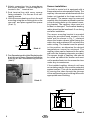
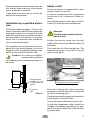
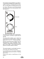
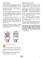
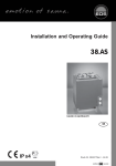
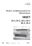
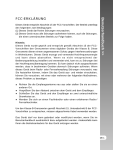
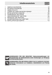
38.AS
GB
Assembly and operating instruction
MADE IN GERMANY
IPx4
Druck Nr. 29342172en 09.10
D
1
English
Table of Contents
General notes .........................................................................................................3
Important notes .......................................................................................................4
Electrical connection ..............................................................................................5
Sample wiring diagram for a sauna system ............................................................6
Installation 38 AS - Wall oven .................................................................................7
Technical data ...................................................................................................7
Minimum clearances .........................................................................................7
Sensor installation .............................................................................................8
Installation by a qualified electrician .......................................................................9
Safety cutoff ............................................................................................................9
Commissioning/Initial operation ............................................................................10
Sauna stones ........................................................................................................11
Maintenance and care ..........................................................................................11
Service Address: ...................................................................................................13
Guarantee .............................................................................................................13
2
GB
Dear Customer,
You have purchased a high quality technical
system which will provide you with many years of enjoyable sauna bathing. This sauna
heating system was constructed in accordance with state-of-the-art European safety
standards, inspected and manufactured in
accordance with the Quality Standard DIN
EN ISO 9001:2000.
This detailed installation and user‘s guide was
created for your information. Please note
especially the important information and the
data dealing with the electrical connection.
We wish you a richly invigorating and restorative sauna bathing experience.
First of all, check whether the sauna system
has arrived at your site undamaged. Register
transport damage claims immediately with
the delivering transport company or please
consult the supplier who provided the equipment to you.
Intended use
This sauna heater is exclusively designed
for the heating of sauna cabins, in connection with an appropriate control unit.
Any use apart from the defined application
shall be regarded as non-intended use. Adherence to the conventional operating, maintenance and servicing conditions is also part
of the intended use.
The manufacturer cannot be made responsible for deviating alterations undertaken on
the authority of the user and any consequential damage. The risk for such measures
shall be borne solely by the person carrying
out the alterations and causing the damage.
Sauna heaters, with the exception of those used for household purposes, must be
equipped with a safety device vis-à-vis the
cover per DIN EN 60335-2-53.
As suitable measure, and depending on the
sauna heater, a rocker switch Type I or Type
II may be installed above the heater.
For installation and electrical connection of
the rocker switch follow the installation instructions supplied with this part.
General notes
Please note that an optimal sauna climate
can be reached only when the cabin, with
its air intake and exhaust, the sauna heating
unit and the control unit have been tuned for
compatibility with one another.
Please note all data and information provided
by your sauna supplier.
The sauna heating units warm your sauna
cabin through means of heated convection
currents. To this end, fresh air from the air
intake vent is drawn in, rises upon warming
(convection) and is then circulated through
the cabin. A part of the used air is pushed out
through the exhaust vent in the cabin. This is
the means by which the typical sauna climate
develops, reaching characteristic temperatures of about 110° C directly under the ceiling
of your sauna, which fall off to about 30-40°C
in the floor area due to the temperature gradient in the sauna cabin. Therefore, it is not
unusual when, for example, temperatures of
110°C prevail in the area of the temperature
sensor over the oven, while the thermometer,
which is installed 20-25 cm under the cabin
ceiling on the sauna wall, registers only 85°
C. With a temperature setting at maximum,
the mean bathing temperature lies between
80°C and 90°C in the area of the upper recliner bench.
Please note that the highest temperature values in the cabin always develop in the area
above the sauna heating unit and that the
temperature sensor and safety limiter must
be installed in this area in accordance with
the control unit installation guide.
At the initial heating, you may notice a slight
odor arising from evaporation of substances
from the manufacturing process. Air out your
cabin after this cycle before you begin with
the sauna bath
(The rocker switch is not included in the delivery scope of the sauna heater.)
GB
3
air intake and exhaust vents must not be
closed. Please observe the information
provided by your sauna cabin supplier.
Important notes
If assembled incorrectly, the system will present a fire hazard.
Please read this installation guide thoroughly. It is especially important to consider applicable dimensions and observe
the following instructions:
• This device has not been designed for
being used by persons (including children)
that are physically or mentally handicapped or have sensory disabilities. Moreover,
it is not allowed to use this device without
sufficient experience and/or knowledge,
unless these persons will be supervised
by persons responsible for their security
or in case they have been instructed how
to use this device.
• Children are to be supervised in order to
make sure that they do not play with this
device.
•
The installation and connection of the
sauna heating unit, control unit and
other electrical equipment must be accomplished only by an expert. In this regard it is especially important to meet the
required safety precautions in accordance
with VDE 0100 v. §49 DA/6 and VDE 0100
part 703/2006-2.
• The sauna heating and control units may
be installed only in sauna cabins made of
suitable, low resin and untreated material
(for example: Nordic pine)
• Only a sauna oven with the appropriate
heating capacity may be installed in the
sauna cabin (see Table 2).
• For the adjustment and control of the sauna heating unit, one of the control units
mentioned later must be used. This control unit must be attached to a suitable location on the outer wall of the cabin, the
associated sensor housings in the interior
of the sauna cabin in accordance with the
installation guide which accompanies the
control units.
•
Caution: Covering and improperly
filled stone receptacles present a fire
hazard.
•
Make certain that no objects have
been placed on the sauna heating
unit before each start-up.
•
Caution: High temperatures on the
heating unit during operation can
cause burns on contact.
• The sauna heating unit is not intended for
installation or placement in a niche under
the bench or under a roof slope.
• Do not start up operation of the sauna heating unit with air intake vents closed.
• The cabin lighting with corresponding
mounting must be of a type that it is splashproof and able to withstand a surrounding
temperature of 140° C. Therefore, only
a VDE-certified sauna lamp of 40 W maximum may be installed for use with the
sauna oven.
•
• There should always be a provision for air
intake and exhaust vents in every sauna
cabin. The air intake vents must always
be aligned behind the sauna heating unit,
ca. 5 to 10 cm above the floor. Please use
the minimum dimensions of the air intake
and exhaust vents listed in Table 1.
• The exhaust vents must always be placed
towards the sauna heating unit diagonally
in the rear sauna wall, lower area. The
4
GB
The sauna system (sauna heating
unit, control unit and lighting etc.)
may be hard-wired to the power source only by a locally certified electrician.
All connecting lines laid on the inside of
the cabin must be made of silicone and
be able to withstand a surrounding temperature of at least 170°C. If single-wired
cables are used as connecting lines, they
must be protected by flexible metal tubing.
The minimum diameter of the connecting
line and the suitable cabin size in proportion to the power supply capacity are listed
in the table.
• During the installation of the sauna heating unit, make certain that the vertical
clearance between the upper edge of the
sauna heating unit and the sauna ceiling
is sufficient . The horizontal (lateral) clearance between the sauna heating unit and
the cabin wall is provided in the dimension
diagram of the respective sauna heating
unit. The required distance between the
lower edge of the sauna heating unit and
the floor is also provided by the dimension
diagram. In case of floor-standing ovens,
the distance is determined by the base.
• Fundamentally, it is important to make
sure that the sauna heating unit is not
placed on a floor that consists of an easily
flammable material (wood, synthetic flooring or similar material). Ceramic tiles or
similar materials are practical in the area
of the sauna.
• Underfloor heating in a sauna leads to increased surface temperature of the floor.
Electrical connection
Your electrician will be able to accomplish
this work without further explanation in accordance with the provided wiring schematic
and with the help of the circuit diagram
mounted inside the respective control unit.
Be sure to note, however, that live wires
should not be visibly laid onto the inner cabin
walls due to safety considerations. For this
reason, the wall element with the air intake
vent is already equipped with cable conduits
in most sauna cabins
Should there be no cable conduits in your
cabin, drill an hole in the cabin wall immediately adjacent to the sauna heating unit
where the cable projects from the sauna heating unit and pull the cable through this hole
towards the exterior and then to the control
unit. The cable as well as all other connecting lines (supply wire to the power source
and to the cabin lighting) on the outside wall
of the cabin should also be protected from
damage, for ex. by installation in cable conduits or by covering with wooden skirting
strips.
• The distance between the oven safety
grid or recliner bench and other flammable materials and the sauna heating unit
are provided in the dimensional data of the
respective sauna heating unit. The safety
grid height must be approximately equal
to the frontal height of the sauna heating
unit.
•
By cleaning of parts with sharp edges
or corners the appropriate personal
protection measures against potential injuries should be taken.
Attention!
Dear customer,
according to the valid regulations, the
electrical connection of the sauna heater and the control box has to be carried
out through the specialist of an authorized electric shop.
We would like to mention to the fact
that in case of a warrenty claim, you
are kindly requested to present a copy
of the invoice of the executive electric
shop.
GB
5
Sample wiring diagram for a sauna system
N L1 L2 L3
4-hr. operating timer
M a i n
power
switch
Temperature limiter
Fuses
Thermostat
Sauna
lamp
Distributor box
Heater
Important! The ground lead (N) must always be connected.
U V W N PE
Connecting Temperature
Installation
Capacity Electrical. Fuse heater cable main regulation
dimensions
acc. DIN Connection
in A
- heater in
range
H/W/D cm
mm²
6,0 kW
7,5 kW
3N AC
50 Hz
400 V
3 x 16
5 x 2,5
6 kW
400 V AC 3N
Minimum
dimensions
of air intake
and exhaust
vents
6 - 8 m³
35 x 4 cm **
7 - 10 m³
35 x 5 cm **
* or in accordance with the instructions of the cabin manufacturer **) during 18 cm ground clearance
1500W
1500W
1500W
1500W
2000W
2000W
2000W
1500W
1500W
For cabin
size
40 - 110° C 78* / 42 / 36
GB
400 V AC 3N
U V W N PE
U V W N PE
All cross sections of a line are minimum diameters in mm² (Copper line)
6
6 kW
400 V AC 3N
1500W
1500W
7,5 kW
1500W
400 V AC 3N
2500W
2500W
2500W
7,5 kW
U V W N PE
Weight
without
stones
without
package
Stone filling
15,0 kg
15,0 kg
Installation 38 AS - Wall oven
Minimum clearances
The minimum height of the sauna cabin must
be 1.90m on the inside.
The vertical clearance between the upper
edge of the sauna heating unit and the
sauna ceiling is at least 90 cm.
36 cm
Cabin wall
Voltage: 400 V AC 3N 50 Hz
8 cm
42 cm
8 cm
Oven safety grid
Technical data
8 cm
Power consumption:
Illust. 1
according to model
Hight: 730 mm at 180 mm floor clearance
1. Center wall mounting over the air intake
vent as in Illust. 2+ 3 and bolt onto cabin
wall with the particle board screws provided
Width: 420 mm,
Depth: 360 mm
Filling capacity for stones: 15 kg
Stray current: max. 0,75 mA per kW heating
capacity
Wall mounting
65 cm
59,5 cm
Sauna oven for use in family sauna
Air
vent
intake
Illust. 2
mi
n
The scope of delivery should include
1 sauna oven
10
cm
34
cm
1 accessory pack with
65 cm
1 ea cable reel PG 16
3 ea self-tapping screws B 4.2 X 9.5
Wall mounting
4 ea particle board screws
Air
vent
1 set of sauna stones, separately in cloth
bag
intake
Illust. 3
The sauna heating unit is intended only for
a supply voltage of 400 V AC 3N.
GB
7
2. Attach connecting line in accordance
with circuit diagram. A circuit diagram is
located in the terminal box.
3. Seal terminal box with cover, spacer
facing outwards. For this use 2 ea. selftapping screws
4. Hook the sauna heating unit into the wall
mounting using the mounting slots on the
rear wall and place against the spacer
(Illust. 3).
Sensor installation
The built-in control unit is equipped with a
thermostat and an a temperature limiter. The
capillary tube sensors are delivered with the
heater unit (packed in the lower section of
the heater). The sensor must be removed
carefully from the heater and fixed in position
in the mounting holes on the sensor mounting bracket. The capillary tubes must not
be bent or damaged. The smallest bending
radius should not be less than 4-5 cm during
and after installation.
The sensor mounting bracket is mounted
(using the provided wood screws) to the
cabin wall as shown in Fig. 7, centered
above the heater exhaust outlet facing the
cabin door and positioned 25 cm below the
cabin ceiling, The bracket must be placed
in this position, as otherwise the desired
temperatures cannot be achieved. The
capillary tubes can be fastened to the cabin
wall with the fastening elements provided.
The excess length of capillary tube should
be rolled up behind the heater and must
not be pushed back into the connection box
under any circumstances.
18 cm
Illust. 4
5. Das Saunaheizgerät mittels Blechschraube
durch die am hinteren Ofenrand befindliche
Bohrung an der Wandhalterung sichern
(Abb.5).
If the installed capillary tubes do not have
an insulating mantle, they must be protected
against contact. This can be accomplished
by running the tubes through the grooves
in the wall paneling and covering them with
appropriate wood molding.
Abb. 5
Mounting screw
Illust. 5
25 cm
20 cm
Illust. 6
8
GB
Please remember that the sensor lines are
thin, flexible tubes that must not be squeezed or subjected to pressure.
Safety cutoff
The sauna heater is equipped with a temperature limiter for security.
These lines must never be cut, as this will
destroy the components.
In case of a malfunction this temperature
limiter cuts off all 3 phases by safety reasons.
Once the temperature limiter has cut off the
current, he must be reset mechanically.
Installation by a qualified electrician
Drill a hole measuring approx. 10 cm in diameter in the cabin wall at the point where the
main power cable is to be inserted. Run the
cable through the hole toward the outside of
the sauna cabin and connect it to the main
power line in a distributor box suitable for
use in moist environments.
Attention:
Cut off the sauna heater from the
mains at first.
Loosen the securtiy screw from the wall
holder of the heater and take the heater off
the holder.
his operation must be performed in accordance with the wiring diagram, the circuit
diagram on the control panel and the regulations of the local EVU and the VDE.
Then open the lid of the terminal box. The
temperature limiter is mounted in the left
lower corner (fig.9).
Caution! The local site installation
must provide for sufficient
fuse capacity and an emergency power cutoff switch.
3 locking pins behind
connecting plug
Illust. 9
Distributor box
suitable for use
in moist environments
Power cable
Temperature limiter for security
Press the 3 locking pins of the connecting
plug back to the rear side of the housing until
you feel a switching point.
Fresh-air
inlet
Illust. 8
Close the terminal box again and restore the
sauna heater in the wall holder.
Secure the heater with the security screw.
In case the temperature limiter should cut
off again immediately after taking into operation, the sauna heater has to be checked
by a specialist.
GB
9
Commissioning/Initial operation
Heater operation is initiated with the timer
unit. You may select a heating period of up
to 4 hours. The timer runs for the selected
time period and then automatically shuts
the heater off.
Thermostat
Timer
The sauna must heat up for approximately 45 minutes to achieve a typical sauna
climate.
The thermostat enables you to select the
temperature you desire within a range of
approx. 40° C to 110° C. Please remember,
however, that the sensors register only the
temperatures in their immediate vicinity.
Therefore, temperatures may differ in other
parts of the cabin. These differences are
typical for sauna climates, however.
The sauna heater is activated through a
clock timer with synchronous motor.
In consequence of the power frequency
(50 Hz) the synchronous motor is making
some noise.
This is not a fault or insufficiency of the
heater !
10
GB
Sauna stones
Maintenance and care
The sauna stone is a natural product. Check
the sauna stones at regular intervals. Strong
infusion concentrates especially can weaken the sauna stones and cause them to
disintegrate over time. Consult your sauna
supplier if necessary.
All sauna heating units are made of lowcorrosion material. Still, to enjoy your sauna heating unit for a long time, you should
maintain and care for the unit. To this end,
always make sure that the vents and reflection plating in the area of air intake are
free of objects. These can easily become
clogged with fuzz and dust when drawing in
fresh air. This reduces the air convection in
the sauna heating unit and can be a cause
of unacceptable temperatures.
Thoroughly clean the sauna stones provided
under running water and then place them in
the stone receptacle so that the convection
air current can circulate easily between the
stones (Illust. 9 + 10).
The number of stones is adequate to create a steam burst, vaporizing about 10 cl of
water per m³ cabin volume. Always wait 10
minutes after infusion before repeating the
infusion. Only then are the sauna stones
sufficiently hot.
Never add more infusion agents or volatile
oils than instructed on the packaging. Never
use alcohol or undiluted concentrates. Caution! Fire hazard!
Clean or de-scale the units when needed.
Refer to your sauna supplier or directly to
the manufacturing plant in case of defects or
signs of wear and tear.
Only use original manufacturer‘s replacement parts, which can be obtained from your
supplier or directly from the manufacturer.
If you do not use your sauna for a significant period of time, always check before
next use that cloths, cleansers or other
objects have not been placed on the sauna heating unit or the vaporizer before
turning them on.
Please be sure to note!
Do not stack the stones in layers; stack them
loosely instead, leaving as many spaces as
possible to allow the rising hot air to circulate.
Remove stones from the sauna heater
only when they are cooled off.
GB
11
For the installation of sauna heaters,
please pay attention to the DIN VDE 0100
part 703 !
This standard makes the following statement
valid in your newest expenditure, since February 2006, paragraph 703.412.05; Quotation:
The additional must be planned for all electric circuits of the Sauna by one or more fault current
protection device (RCDs) with a calculation difference stream not more largely than 30 mA, excluded of it is Saunaheating.
The EN 60335-1 DIN VDE 0700 part 1 of January 2001 states the following in paragraph 13;
quote:
The leakage current may not exceed the following values during operation:
- for stationary heaters of protection class I 0,75
mA; or 0,75 mA each kW input of the appliance,
depending on the higher value, at a maximum value of 5 mA.
If the appliance is equipped with a protective
device for leakage current (ELCB), please pay
attention to the fact that no other electrical
units will be protected by this ELCB.
Under current manufacturing methods, it is
not yet possible to produce tubular heating
elements for sauna heaters which do not attract moisture on each end from the surrounding air. It is also possible that moisture from
the surrounding air has been concentrated in
the magnesium-oxide filling in the heating elements during transport or storage and is now
causing the ELCB to be triggered.
In this case, the oven must be heated up under
supervision of an expert, during which the PE
conductor is not connected. After about 10
minutes, when moisture has evaporated from
the heating elements , the oven must be reconnected to the PE conductor!
If the sauna heater is not in use for a significant period of time, we recommend running it
every 6 weeks, so as to avoid moisture concentrating in the heating elements.
Therefore, should the ELCB be triggered during start-up, the electrical installation must be
checked.
Installation of the sauna heater and control
unit may be undertaken only by an authorized
electrician. Without documentation of such installation, a warranty is fundamentally invalid.
12
GB
Guarantee
The guarantee is taken over according to
the legal regulations at present.
Manufacturer’s warrenty
- The period of warrenty starts from the
date of purchase and lasts up to 2 years
for commercial use and 3 years for private use.
- Always include the completed warrenty
certificate when returning equipment.
- The warrenty expires for appliances
which have been modified without
manufacturer’s explicit agreement.
- Damages caused by incorrect operation
or handling through non-authorized persons are not covered under the terms of
warranty.
- In the event of a claim, please indicate the
serial number as well as the article code
number and type name with expressive
description of the fault.
Please keep this address in a safe place together with the installation guide.
- This warrenty covers damaged parts but
no defects due to
wear and tear.
To help us answer your questions quickly
and competently, please provide data printed on the ID plate, to include system type,
article no. and serial no., in all inquiries.
In case of complaint please return the
equipment in its original packaging or other
suitable packaging (caution: danger of
transport damage) to our service department.
Always include the completed warrenty
certificate when returning equipment.
Possible shipping costs arising from the
transport to and from point of repair cannot
be borne by us.
Service Address:
Outside of Germany please contact your
specialist dealer in case of warranty claims.
Direct warranty processing with our service
department is in this case not possible.
EOS-WERKE GÜNTHER GmbH
Adolf-Weiß-Straße 43
35759 Driedorf-Mademühlen, Germany
Fon: +49 (0)2775 82-0
Equipment start-up date:
Fax: +49 (0)2775 82-431
[email protected]
Stamp and signature of the authorized
electrician:
www.eos-werke.de
GB
13
Handling procedures for return shipments (RMA) - Details for all returns !
Dear customer
we hope that you will rejoice in the ordered articles. Just in case that you are not entirely contented as an
exeption, please follow the procedures specified below.This enabling us to ensure a quick and smooth
handling of the return shipment.
Please absolutely respect for all returns!
• Please add the available RMA-voucher always completely filled out together with an
invoice copy to the return shipment! Do not stick it on the goods or on the packaging.
We do not accept the return shipment without these papers.
• Not prepaid parcels will be refused and returned to Sender! Please always ask for the
RMA-No. for the cheapest return.
• Please pay attention that the goods have to be sent back without visible marks of
use in the original scope of delivery and in original packing.
• We recommend to use an additional solid and break-proof covering box which
should be padded out with styrofoam, paper or similar. Transport damages as a result of
faulty packing are for the sender‘s account.
Form of complaint:
1) Transport damage
2) Faulty goods
• Please check the content • The implied warrenty peof your parcel immediately
riod is 2 years.Please
and advise the forwarding
contact your dealer in
company of a claim (parcase of faulty or wrong
cel service/ freight forwararticles or missing acder)
cessories. He will discuss
with you the individual
• Do not use damaged
case and try for immediate
goods!
and customer-friendly solution.
• Ask the forwarder for a
written
acknowledge• For economic returns
ment of the damages.
within Germany you will
get an RMA-number
• Report the claim prompfrom the manufacturer.
tly by phone to your
dealer. He will discuss
• All returns have to be in
with you how to act in this
the original packing of
case.
the goods with corresponding accessories.
• If the transport box has
Please repack the goods
been damaged, please
to avoid damages. In case
use an additional covering
of wrong delivery, please
box. Do not forget to add
do not use this article !
the acknowledgement of
the damage of the forwarding company !
14
GB
3) Problems of installation
and functioning
• Please read the manual
carefully first of all and
pay attention to the indicated assembly or installing
instructions.
•
Your dealer should be
the first contact person
because he knows his
products best and also
knows possible problems.
• In case of function
problems with an article, please check at first
whether there is an obvious material defect. The
quality system in our factory reduces malfunctions
of new appliances to almost zero.
.