1
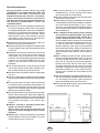
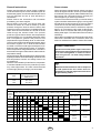
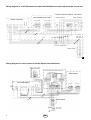
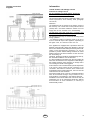
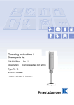
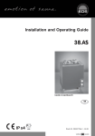
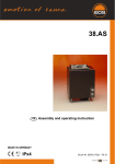
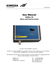
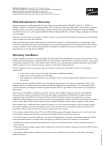
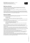
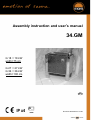
Assembly instruction and user’s manual
34.GM
G 18 = 18 kW
width=75 cm
G 27 = 27 kW
G 36 = 36 kW
width=100 cm
GB
IP x4
Druck Nr. 29342877en / 44.06
GB
1
Special Instructions
10 cm
100 cm
(75 cm)
10 cm
a) b)
43 cm
80 cm
l This device has not been designed for being used
by persons (including children) that are physically
or mentally handicapped or have sensory disabilities.
Moreover, it is not allowed to use this device without
sufficient experience and/or knowledge, unless
these persons will be supervised by persons
responsible for their security or in case they have
been instructed how to use this device.
lChildren are to be supervised in order to make sure
that they do not play with this device.
lThe sauna heating unit is designed for operation with
an input voltage of 400 V AC 3N through the sauna
control unit.
l Installation and electrical connection of the sauna
heating units, the control unit and other electrical
components must be performed by a qualified
electrician. The special safety requirements specified
in VDE 0110 v. § 49 DA/6 and VDE 0100, Part 703/
2006-2 must be observed during electrical
installation.
l The sauna heating and control units may be used
only in sauna cabins constructed of suitable, resinfree, untreated material (e.g. Nordic spruce).
l The sauna cabin must have a minimum inside height
of 2.10 m.
l Only one sauna heater providing the required heating
output may be installed in the sauna cabin (see Table
2.
l Every sauna cabin must have a fresh-air inlet and
an exhaust outlet. All ventilation inlets/outlets must
be positioned behind the sauna heating unit and
approx. 5-10 cm above the floor. Minimum inlet/outlet
dimensions are listed in Table 1.
l The exhaust outlet must be positioned in the lower
section of the rear wall of the sauna cabin, diagonally
opposite the sauna heating unit. Fresh-air inlets and
exhaust outlets must not be closed. Please observe
the instructions provided by your sauna cabin
supplier.
l Caution: Covered or improperly filled stone
grates can cause fire hazards.
Please ensure that no objects have been left
lying on the sauna heating unit prior to each
operation.
l Caution: Due to the high temperatures generated
during operation of the sauna heating unit, direct
contact with the unit can cause burns.
minimum 130 cm
l The sauna heating unit is not designed for
installation/use in a niche, beneath the reclining
bench or beneath an inclined ceiling.
l The sauna heating unit must not be operated when
the fresh-air inlet is closed.
l Cabin lighting and lighting installation components
must be splash-resistant and suitable for operation
at environmental temperatures of up to 140°C.
Therefore, only VDE-tested sauna lighting systems
(max. 40 Watt) may be used in connection with the
sauna heating unit.
l The complete sauna system (sauna heating
unit, control unit, lighting system, etc.) may be
connected to the main power system by a
locally certified electrician only. All electrical
wiring installed inside the cabin must be suitable
for use at environmental temperatures of up to 140°
C. Silicone cables are recommended. If single
filament cables are used, they must be protected
with flexible metal tubing. Minimum diameters for
connection cables and suitable cabin sizes for
specific heating output values in kW are listed in
Table 2.
l When installing the sauna heater, please ensure
that the vertical height between the top surface of
the sauna heater and the roof of the sauna is at
least 130 cm, and that the horizontal separation
between the heater and the cabin wall or other
flammable materials is at least 10 cm. Ensure that
the heater is not placed on a floor made from highly
flammable materials (e.g. wood, plastic flooring).
Ceramic tiles or similar are most suitable for the
sauna area.
l The distance between the heater guard and/or bench
and other flammable materials must be at least 10
cm. The height of the heater guard must be the
same as the height of the front of the stove.
l To be used with all EOS sauna control units suitable
for additional power control units.
During operation of the sauna, very high
temperatures are created within the cabin and
particularly at the stove. If the stove is not
installed correctly there will be a fire hazard.
Please read these installation instructions
carefully. You should pay particular attention to
the specified measurements and to the
instructions below.
a) without mill: minimum distance 10 cm
b) with mill: minimum distance 58 cm
2
GB
General instructions
Sauna stones
Please note that optimum sauna climate conditions
can be achieved only if the cabin ventilation (fresh air
and exhaust) system, the sauna heater and the control
unit are designed and set to work efficiently in
combination.
Please observe the instructions and information
provided by your sauna supplier.
Sauna heating units heat your sauna cabin with
warmed convection air. Fresh air drawn by suction
pressure through the fresh-air inlet is heated, rises
upward (convection) and is then circulated within the
cabin. Some of the consumed air is forced out of the
cabin through the exhaust outlet. This process
produces a typical sauna climate, with temperatures
of approximately 110° C immediately below the ceiling
and a temperature gradient that produces low
temperatures of approximately 30-40° C at floor level.
Thus it is not unusual for the temperature sensor above
the heater to register 110° C, while the thermometer
mounted on the sauna wall approximately 20-25 cm
below the cabin ceiling shows only 85° C. Ordinarily,
sauna temperatures range between 80° C and 90° C
at the level of the upper recliner bench at the maximum
temperature setting.
Please remember that temperatures are always at their
highest just above the sauna heating unit and ensure
that temperature sensors and safety limiters are
mounted there.
When the unit is heated up for the first time, evaporation
of residual substances from the production process
may cause slight odors. The cabin should be aired
out thoroughly before you begin your sauna bath.
Sauna stones are natural materials. Check your sauna
stones at regular intervals, since they are susceptible
to the effects of strong steam-water additives and may
decompose over a long period of time. Consult your
sauna supplier if you have any questions.
The sauna stones delivered with your sauna heating
system should be washed thoroughly in running water
and placed in the stone grate in such a way that the
convection-air can flow freely between the stones.
The quantity of sauna stones is sufficient to vaporize
approx. 10 cl of water per cubic meter of cabin space.
Wait for about 10 minutes after each pouring before
adding water again. This allows the stones to heat up
sufficiently.
Never add more additives or ethereal oils to the steam
water than is indicated on the containers. Never use
alcohol or undiluted concentrates. Caution! Fire hazard.
Power input
in kW
18,0
27,0
36,0
URGENT WARNING!
Stones must not be piled in layers in the stone
grate on the sauna heater but instead placed
in a loose arrangement in order to ensure
that rising hot air can flow freely between
the stones.
With Electric Sauna Stoves with an output of
27 kW upward the mill wheel must be
installed onto a 60 mm high base which must
be provided by others.
Minimum dimensions of
fresh-air inlets and exhaust
outlets in cm *)
50 x 6 cm
50 x 9 cm
50 x 10 cm
Table 1
Required heat outputs and connection ratings
Cabin size in m³ (manufacture conforms to RAL for cabins inside buildings)
Heat
output in
kW
4 4-6 6-8 7-10 9-14 14-18 18-25 24-30 24-34 35-40 40-50 50-65 65-75
12
Min. cross-section of the mains cable in
mm2
Connection to
400 V 3N AC
FuseA
5 x 4²
3 x 25
5 x 6²
3 x 35
5 x 10²
3 x 50
mind.
5 x 10²
3 x 63
15
18
21
24
27
30
36
Tabelle 2
GB
3
Wiring diagram for 12-27 kW sauna stove with load distribution to control unit and power control unit
Power control unit LSG 18 90 7372 00
Sauna heater up to 27 kW
S2 S1 U V W
N N N
sensor
L3 L2 L1
limiter
Sauna control unit
max. 9 kW
max. 18 kW
N
N
U1 V1 W1
4 3
safety contactor
U2 V2 W2
4 3
2 1
safety contactor
N N
2 1
5 x 1,5²
12-16 kW: 4²
18-21 kW: 6²
24-27 kW: 10²
2 x 1,5²
5 x 6²
5 x 2,5²
3 x 16 A junction box
Mains switch
L1 L2 L3 N
Wiring diagram for sauna heaters to 36 kW without load distribution
Temperature sensor
Sensor housing
Power control unit to 36 kW 90 8771 00
Control contactor B
Safety contactor
Control contactor A
Limiter
Sauna heater
N
S1
U V W
sensor
L3 L2 L1
limiter
Sauna-Steuergerät
L1 L2 L3 N N N
3 x 1,5²
Mains switch
30 kW: 10 mm²
36 kW: 10 mm²
4
GB
max. 18 kW
N U1 V1 W1
N U2 V2 W2
4
4
S1 A B
Outlet:
Safety contactor
3 x 1,5²
max. 18 kW
3 2
1
3 2
1
Terminal connection
diagrams
Information
Sauna heaters and leakage current
Instructions Leakage current
For the installation of sauna heaters, please pay
attention to the DIN VDE 0100 part 703 !
This standard makes the following statement valid in your
newest expenditure, since February 2006, paragraph
703.412.05;
Quotation:
The additional must be planned for all electric circuits of
the Sauna by one or more fault current protection device
(RCDs) with a calculation difference stream not more
largely than 30 mA, excluded of it is Saunaheating.
The EN 60335-1 DIN VDE 0700 part 1 of January 2001
states the following in paragraph 13; quote:
The leakage current may not exceed the following values
during operation:
- for stationary heaters of protection class I 0,75 mA; or
0,75 mA each kW input of the appliance, depending on
the higher value, at a maximum value of 5 mA.
If the appliance is equipped with a protective device for
leakage current (ELCB), please pay attention to the fact
that no other electrical units will be protected by this ELCB.
Under current manufacturing methods, it is not yet
possible to produce tubular heating elements for sauna
heaters which do not attract moisture on each end from
the surrounding air.
Therefore, should the ELCB be triggered during start-up,
the electrical installation must be checked.
It is also possible that moisture from the surrounding air
has been concentrated in the magnesium-oxide filling in
the heating elements during transport or storage and is
now causing the ELCB to be triggered.
In this case, the oven must be heated up under supervision
of an expert, during which the PE conductor is not
connected. After about 10 minutes, when moisture has
evaporated from the heating elements , the oven must be
reconnected to the PE conductor!
If the sauna heater is not in use for a significant period of
time, we recommend running it every 6 weeks, so as to
avoid moisture concentrating in the heating elements.
Installation of the sauna heater and control unit may be
undertaken only by an authorized electrician. Without
documentation of such installation, a warranty is
fundamentally invalid.
to 18 kW power control unit
to 18 kW power control unit
GB
5
"
Warranty
Attention!
The warranty may be transferred under the terms of the
law applicable at that time.
Dear customer,
according to the valid regulations, the electrical
connection of the sauna heater and the control
box has to be carried out through the specialist
of an authorized electric shop.
We would like to mention to the fact that in case
of a warrenty claim, you are kindly requested to
present a copy of the invoice of the executive
electric shop.
Manufacture Guarantee
- The period of warrenty starts from the date of
purchase and lasts up to 2years for commercial use
and 3 years for private use.
- The guarantee will only be deemed valid upon
presentation of the appliance's purchase receipt.
- Any alterations made to the appliance without the
express permission of the manufacturer shall render
all warranty claims invalid.
- Any faults arising due to repairs or actions carried
out by unqualified persons or due to improper use
also render all warranty claims invalid.
- When submitting a warranty claim, the customer
must quote the serial number, the item number, the
appliance name and a detailed description of the
fault.
- This guarantee covers compensation for faulty
components except for imperfections caused by
normal wear and tear.
In the case of complaints, the appliance should be sent
to our service department in its original packaging or in
other suitable packaging (PLEASE NOTE the danger
of damage during transport).
Always send this guarantee form, filled in, with the
appliance.
We cannot assume any transport costs that may arise
from sending the appliance backwards and forwards.
If a warranty claim arises outside Germany, please
contact your distributor. In such cases, there can be no
direct contact with our service centre about the
guarantee.
Date of first operation:
Stamp and signature of the authorised electrician:
Service address:
EOS-Werke Günther GmbH
Adolf-Weiß-Straße 43
35759 Driedorf, Germany
Tel. +49 (0)2775 82-240
Fax+49 (0)2775 82-455
[email protected]
www.eos-werke.de
6
GB