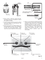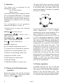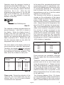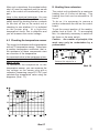
1
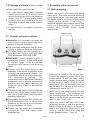
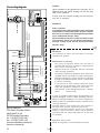
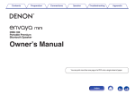
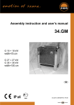
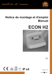
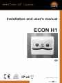
Installation and user's manual
ECON H1
GB
IP x4
Druck Nr. 29342787en / - 22.06
1
Contents
1.
1.1
1.2
1.3
General information
Technical Data
Package contents
General safety precautions
3.
Operation
3.1.1 Dry (Finnish) sauna
3.2 Steam operation
3.2.1 Supplemental heating function
3.2.2 Low water shutoff
2.
Assembly of the control unit
2.1 Wall mounting
2.2 Electrical connection
2.2.1 Connecting the sauna oven
2.2.2 Connecting the vaporizer
2.2.3 Connecting the sauna lamp
2.3 Connecting the sensor lines
4.
Troubleshooting
4.1.1 Error indicator in display
4.2 Overheat safety shutoff
4.3 Monitoring the temperature sensor
5.
Heating time extension
6.
Guarantee
Manufacturer’s warrenty
1. General information
1.1
Technical data
Rated voltage:
400 V 3 N 50 Hz AC
Breaking capacity:
max 9 kW resistive load (AC 1 operation) Climatic operation: 6
kW + 3 kW for vaporizer unit, upgrade to 36 kW possible through
connection to circuit breakers
Heating time shut-off:
6 h or optionally 12 h after removal of resistance
Display:
Protection type:
two-digit, 7 segmented display
IPx4 in accordance with DIN (German Standards Institution)
40050, Splashproofing
Control range, sauna operation: 70 to 110° C
Control range, steam operation: 30 to 65° C
during steam operation control: time proportional vaporizer
control
Sensor system:
KTY-Sensor with overheat shutoff protection at 139° C
Water level control:
low water level in the vaporizer causes automatic shutoff after
two minutes of low water level
Control characteristics:
digital two-step control of -20° C - max. cab temperature
Ventilation capacity:
max. 200 W max. 1A
Light:
max 200 W max. 1A
Supplemental heating function: 20 min after shutoff of steam program
Error display:
blinking LED for connector interruption to oven sensor
connector interruption or failure of the safety temperature
shutoff
Environmental temperature: 0º C to + 40º C
Storage temperatures:
20º C to +70º C
2
english
1.2 Package contents
2. Assembly of the control unit
(subject to change)
2.1 Wall mounting
Included with the control unit are
1. an oven-sensor board with overheat
shutoff protection, KTY-sensors with
sensor housing, two 3x25 mm fastening
screws and a 1,7 m long sensor cable.
2. a plastic bag with three 4 x 20 mm
fastening screws and three spacer
tubes
3. a replacement overheat protection
module
Mount the control unit outside the sauna
cabin only. The most practical mounting
point would be the wall area onto which
the sauna oven is mounted on the inside,
except on the outside of the cabin. If
electrical conduits are present, mount the
control unit accordingly. To mount the
control unit, please follow these
instructions:
Control knobs
1.3 General safety precautions
l Attention: It is forbidden to install the
control box in a closed switch cabinet or
behind a wooden panelling!
l The electrical installation may be done
only by a qualified electrical technician.
l You must comply with the regulations of
your electrical supplier and applicable
VDE regulations (DIN VDE 0100).
l WARNING: Never attempt repairs or
installations yourself, as this could result
in serious injury. Only a qualified
technician may remove the housing
cover.
l Please note the dimensions in the
assembly instructions, especially when
installing the temperature sensor. The
temperature above the oven is critical for
the
temperature
setting.
The
temperature can be held within operating
parameters and a minimal temperature
gradient inside the sauna cabin can be
achieved only if unit is assembled
correctly.
l The device may only be used as intended
as a control unit for sauna ovens up to 9
kW. (Up to 36 kW when combined with a
breaking capacitor).
l Completely disconnect the control unit
from the electrical circuit, i.e. flip all circuit
breakers or the main circuit breaker
during installation or repair.
l Please note the safety and installation
information from the sauna oven
manufacturer.
Fastening screws
Illust. 1
1. Remove the cover of the control unit.
Loosen the fastening screws below the
control panel. If your unit uses control
knobs, remove them. Enlarge the holes
for the electrical cables (Illust. 4) with a
sharp knife. Drill the threaded holes for
the included 4 x 20 mm wood screws
according to Illust.s 3 & 3.1.
2. Insert one of the wood screws into the
upper middle hole. This screw will be
the mounting point for the control unit.
Make sure the screw is projecting out
about 3 mm. (Illust. 3.2)
3. Hang the control unit onto the 3 mm
projecting screw. Lead the electrical
cable through the holes you enlarged in
step 1 and screw the lower part of the
housing onto the cabin wall using the
lower threaded holes. (Illust. 4)
english
3
threaded holes
Please note:
upper threaded hole
If the sauna cabin is not equipped with
electrical conduits, the electrical cables
must be lead along the outside of the cabin,
preferably in one of the recesses between
the wood boards. Therefore, you have to
mount the control unit farther away from
the cabin wall, so you can lead the cables
into the unit. In this case, use the included
spacer tubes as shown in Illust. 3.3
eye level
20 cm
Illust. 3.1
3
Illust. 3.2
4
lead hole for
sensor lines
lead hole for lamp,
ventilator
Illust. 4
15 cm
ca. 34 cm
lead hole for power
supply lead wire
Illust. 2
lead hole for
vaporizer connector
lead hole for
oven connector
eye level
ca. 20 cm
2.2 Electrical connection
The electrical connection may only be
done by a qualified electrical technician
under authority of the regulations of the
local power supply company and those of
the VDE.
3
Illust. 3.3
english
In general, there can only be one permanent connection to the power supply network,
to include a device which allows the unit to
be disconnected from the power source with
a contact distance of at least 3 mm from all
terminals.
All electrical installations and connector
cables inside the cabin must be able to
withstand temperatures up to 140°C.
Please use the table below to determine
the required cable diameters for this task.
Attach the power supply lead wire as shown
in Illust. 5 to the power supply terminals of
the control unit. Connection instructions are
printed directly in the control unit.
Lead wire for cabin
lighting
Warning: Always connect the sauna
oven's neutral conductor. During
steam operation one of the phases
shuts down, therefore the heat doesn't
spread evenly. In consequence the
neutral
conductor
becomes
energized.
2.2.1 Connecting the sauna oven
Assemble the sauna oven and the
vaporizer according to the instructions
provided by the manufacturer in front of the
air intake opening. Lead the silicon lines
and electrical conduits to their respective
terminals on the control unit and connect
them according to the circuit diagram
printed there.
Power supply
lead wire
Please note: If no electrical conduits are
present, drill a hole with a diameter of 10
mm next to the air intake opening and lead
the oven control cables through this hole
to their corresponding terminals (U V W) in
the control unit. To protect the silicon lines
from external influences, install them in a
shielded fashion. For this task, use a fitting
cable or simple PVC conduit and lead the
silicon cable through it to the control unit.
2.2.2 Connecting the vaporizer
To connect the vaporizer, use silicon
connecting lines 4 x 1,5 mm2 as well.
Air intake opening
Illust. 5
connector
capacity in
KW
appropriate for
cabin sizes
in m³
minimum diameter in mm² (copper wire)
connection to 380 V 3N AC
power supply lead wire
to the control unit
oven connector cable
control unit for oven
safety fuse
capacity in A
4,5
4 - 6
5 x 2,5 mm²
5 x 1,5 mm²
3 x 16
6,0
6 - 10
5 x 2,5 mm²
5 x 1,5 mm²
3 x 16
7,5
8 - 12
5 x 2,5 mm²
5 x 1,5 mm²
3 x 16
9,0
10 - 14
5 x 2,5 mm²
5 x 1,5 mm²
3 x 16
english
5
Warning: When connecting the vaporizer
make sure it is correctly attached to the
water bath (WB) and low water shutoff
(WM). If you switch these connections, you
disable the water deficiency function and
bypass the thermostat. As a result, the
vaporizer will overheat.
This is a fire hazard!!
Please note that the following
measurements are based on values
provided by the unit quality assurance by
the European Standard EN 60335-53-2. In
principle, you must mount the oven sensor
where temperatures are the highest. Illust.
7 gives you an overview of the mounting
point of the sensor.
Illust. 6 shows the circuit diagram. The
control unit can detect water deficit if there
is a zero-potential feed at the WM-input.
WQ
WS
N
connectors in the control
unit
brown
blue
green/yellow
black
20 cm
WQ = water quench
WS = water shortage
TL = temperature limiter
TL
3 kW
vaporizer
Illust. 7
Illust. 6
2.2.3 Connecting the sauna lamp
The sauna lamp must be splashproof (by
Standard IP54) and suitable for
temperatures up to 140°C. The sauna
lamp can be mounted anywhere except in
the area of the rising hot air above the oven.
Mounting the oven sensor
1. Mount the oven sensor in cabins up to
2 x 2m according to Illust. 7 and 8, in larger
cabins according to Illust.s 7 and 9.
2.3 Connecting the sensor lines
You should not install sensor and power
supply lines together, or lead them through
the same conduit. This can lead to
interferences in the electronics, such as
"fluttering" in the switch protectors. If it is
absolutely necessary to install them
together, or the wire is longer than 3m, you
should use a shielded sensor line such as
the LIYLY-O (4 x 05, mm²). Connect the
shielding to mass in the control unit.
35 cm
19 cm
Illust. 8
6
english
Illust. 9
hole
red
sauna ceiling
red
white (Limiterf)
housing
white (Limiter)
Sensor
Ô
sensor
board
sensor housing
sensor line
center sensor housing
on middle section
terminals in the
control unit
Illust. 10
shutoff sensor
2. Drill a hole to lead the cable through,
preferably through the middle of one of
the wooden boards.
Illust. 11
5. After you are finished installing and have
made sure the control unit is functioning
properly, check the line for overheat
shutoff protection for short circuits. To
do this, release one of the white lines in
the sensor housing. The control unit's
safety relay should now fall, i.e. the
heating circuit should now be
interrupted.
3. Lead the sensor cable through the drilled
hole and attach it to the sensor line
according to Illust. 11.
4. Attach the lines for the shutoff (white) and
the temperature sensor (red) according
to Illust. 10 to the sensor board. Then
insert the sensor board into the housing.
Æ LED display
operational (green)
Å display for
humidity level
Ç LED display
heating (red)
À function
Á temperature
selection
selection
 button for
increasing value
Ä button for CLIMAmode
à button for decreasing
value
Illust. 12
english
7
3. Operation
The green LED above the button will light
up. Depending on the current temperature
in the sauna cabin, the sauna oven's red
operational display Å will light up, signaling
the oven is heating.
The control unit is intended for two
operational modes:
- Dry (Finnish) sauna
- Steam sauna
In the dry (Finnish) sauna mode the sauna
air is not steamed additionally. The sauna
air temperature can be set up to 110°C.
During steam operation the maximum
temperature is limited to 65°C for safety
reasons.
0
The configuration of the operation
elements are shown in Illust. 12.
À Switch
knob to select the following
functions
Heating
Use the right hand dial Á to set the desired
cabin temperature.
For a higher
temperature turn the knob clockwise, for a
lower temperature counter-clockwise.
= sauna oven on
Light/heating
cabin lighting on
= sauna oven +
Fan/light/heating
oven + cabin lighting + fan on
Fan
= fan (if installed) on
Licht
= light is on
The temperature can be set from 70°C up
to 110°C (during sauna operation). Please
take into consideration that these values
can vary by a few degrees, depending on
cabin configuration. For safety reasons the
temperature is measured in the hottest
area of the cabin above the oven. This
temperature serves as a value for the
temperature around the sauna benches.
Depending on oven capacity and
placement of the fresh air vents,
undesirable influences can alter these
measurements, not allowing the maximum
temperature to be reached. The control
range is laid out so that normal
temperatures from 90 to 95°C in the bench
area can be preselected.
= sauna
0 = all installed components are off
Á Turning dial for temperature selection
 Button for increasing steam level
à Button for decreasing steam level
Ä Button for CLIMA - mode
Å LED-display for steam level
Æ Standby display
Ç Operation display for sauna oven
3.2 Steam operation
A suitable vaporizer unit up to 3 kW and
230 V AC is required for steam operation.
The control unit "clocks" the vaporizer
based on the user-set steam level. Use
the three buttons below the digital display
Å to set the vaporizer performance level.
3.1 Startup of dry (Finnish) sauna
operation
Switch the sauna oven with the left hand
dial to À operation, i.e. one of the switch
positions with the
symbol.
8
english
In the case of the symmetrically wired oven
(equal heating power for each phase), onethird of the heating power of the sauna oven
is consequently switched off. This serves
both to protect the user from excessive
temperatures as well as to limit the switch
capacity to 3 kW per phase.
Operation using the vaporizer function is
activated via the middle CLIMA key Ä. The
value set for the last operating cycle
appears in the display (in case of first-time
operation, this is 0). With the two
programming keys placed to the left and
right of the CLIMA key, (up and down),
Illust.13, you can program in amounts
between 0 and 99%.
The humidity level aimed for depends
strongly on the configuration of the sauna
cabin, the type of sauna oven used and the
power of the vaporizer. Therefore, it is
important that you find your personal climate
zone. Always choose the temperature first
(from 30 to 60°C) and then the steam level.
Press CLIMA key once
Illust. 13
The vaporizer is always activated when an
amount between 1 and 99% is shown in
the display. When the display shows 0,
please note that the vaporizer is not
activated, but as with steam operation in
general, the maximum temperature in the
cabin is limited to 65°C. Please note also
that the vaporizer starts up only after the
temperature falls to this level.
Tip: For the preheating time, select a higher
steam level (=duration of operation), so that
the volume of water contained in the
vaporizer (up to 8 liters depending on the
model) will be heated more rapidly. When
the oven and vaporizer are optimally
adjusted to the sauna cabin, the values for
humidity given in Illust.15 can be reached at
100% duration of operation.
Temperature
The value shown in the display reflects the
time-proportional vaporizer adjustment.
Therefore, the display cannot be adjusted
for or show the relative humidity, but rather
the frequency of vaporizer activation. The
table (Illust.14) is meant to clarify this.
Amount shown
in display
99
75
50
25
0
50 %
60 %
70 %
80 %
Illust. 15
These amounts are reachable, although
they are higher than the amounts actually
needed.
Vaporizer
On
Off
99 %
75 %
50 %
25 %
0
60°C
50°C
40°C
30°C
Relative humidity
Therefore, reduce the amounts after the
preheat cycle; to do so, set a lower value
using the program key Ã. Please note that
the cabin temperature is highest under the
cabin ceiling, although the relative humidity
is proportionally lower at this point. The
relative humidity rises in proportion to the
falling temperatures from the cabin ceiling
to the cabin floor.
1%
25 %
50 %
75 %
100 %
Illust. 14
Please note: During the activation of the
vaporizer, the oven heats with only two
phases; that is, one of the switch phases
is switched to the vaporizer.
english
The following diagram (Illust. 16) shows
you the temperature values proportional to
the relative humidity for the most common
types of sauna bathing and comfort zones.
9
Temperature in °C
Please note: Some vaporizers are
equipped with a buzzer, providing an
acoustical signal as an additional warning
when the thermostat in the vaporizer
registers a water deficit.
sauna
herbal/steam-warm air
bath
4. Troubleshooting
warm-air bath
Unit cannot be put in operation mode
Check to see whether socket (230V AC) is
in contact with all three prongs. Check the
fine adjustment on the board.
Blinking green LED
1. Check overheat shutoff in the sensor
housing
2. Check lines leading to the overheat
shutoff
relative humidity in %
Illust. 16
3.2.1 Turning off steam operationsupplemental heating function
Blinking red LED
1. Check temperature sensor
2. Check lines to temperature sensor
The steam operation program is stopped
by pressing the CLIMA key. At the end of
operation, a drying program is begun. The
sauna is automatically heated to about
90°C for 20 minutes. The operating
sequence of the supplemental drying program is exhibited by the blinking 7segmented display.
Unit can be turned on, oven heats, but
needed temperature cannot be reached.
1. Check temperature sensor
2. Check lines to temperature sensor
3. Check assembly of sensor housing.
4. Check supply air and exhaust air
Poti Dial for temperature control must stop
at right and left and must not be able to be
turned 360°.
The supplemental heating temperature has
been preset by the manufacturer to 90°C
and is not adjustable. If the supplemental
heating program must be interrupted or if it
is necessary to turn the system off
completely, set the function dial to 0.
4.1 Checking the overheat safety
shutoff
3.2.2 Low water shutoff
Vaporizer tanks are equipped with an
overheat safety shutoff as a state-of-theart standard. When this safety is activates,
for example, when the water level in the
vaporizer tank is too low (water deficit) and
is not filled within two minutes, the control
unit turns off for safety reasons and two
dashes(--) appear on the display.
10
The control unit is equipped with a safety
shutoff in the form of a temperature
governor. This temperature governor is
located in the sensor housing over the
sauna oven and is connected to the
control unit with the white sensor lines. If
the sauna oven is not turned off due to a
flaw in the electronics, the overheat
shutoff registers temperatures starting at
140°C and breaks the circuit to the safety
shutoff of the control unit and
consequently to the sauna oven.
english
Note to the electrical technician: You can
easily check the function of the overheat
safety shutoff by shorting the two contacts
for the shut off line on the control unit or
checking to see whether 0 V is indicated
on the proper plug. At a high-ohm
temperature check, this is defective and
you will measure the control voltage.
4.3 Checking the temperature sensor
The control unit determines the temperature
with a KTY temperature sensor. These have
a positive temperature coefficient; that is,
the resistance of these components rises
as a function of the temperature.
An important value is the resistance at normal room temperature. At 20°C, this is
about 1,9 k!"
To determine the temperature on the
temperature sensor, you can measure the
low voltage on the sensor plug with a
voltmeter (measuring range 20 V DC) and
calculate the temperature value using the
diagrams (Illust. 17).
5. Heating time extension
The control unit is adjusted for a maximum
heating time of 6 hours at delivery. This
heating time limit can be extended to 12
hours.
To do so, it is necessary to remove a
resistor underneath the dial on the control
board.
To get the correct position of the resistor,
please look at Illust. 18. To accomplish
this, it is absolutely necessary to switch off
the fuses or the main switch.
Caution: As a matter of principle, this
work may only be undertaken by a
professional!
ä
After such a shutdown, the overheat safety
shut off must be replaced and the sauna
unit or the control unit monitored by an expert.
Remove this resistor for a
heating time of 12 h
Illust. 18
2,5
2,25
2
1,75
Illust. 17
english
11
Connecting diagram
Caution
safety protection
TB
control relay
Dear customer,
according to the valid regulations, the electrical
connection of the sauna heater and the control
box has to be carried out through the specialist
of an authorized electric shop.
We would like to mention to the fact that in case
of a warrenty claim, you are kindly requested to
present a copy of the invoice of the executive
electric shop.
to the circuit breaker
Guarantee
The guarantee is taken over according to the legal
regulations at present.
connection to main
power source
light
N
WB S1
max. 9 kw
sauna
lamp
ventilator
ventilator
W
V
U
-
The period of warrenty starts from the date of
purchase and lasts up to 2 years for commercial use
and 3 years for private use.
-
Always include the completed warrenty certificate
when returning equipment.
-
The warrenty expires for appliances which have been
modified without manufacturer’s explicit agreement.
-
Damages caused by incorrect operation or handling
through non-authorized persons are not covered under
the terms of warranty.
-
In the event of a claim, please indicate the serial
number as well as the article code number and type
name with expressive description of the fault.
-
This warrenty covers damaged parts but no defects
due to
wear and tear.
N
sauna oven
oven sensor
N
L3 WM
Limiter
L1
L2
Sensor
Sauna Control Unit
Attention!
Manufacturer’s warrenty
Service Address:
EOS-Werke Günther GmbH
Adolf-Weiß-Str. 43
35759 Driedorf-Germany
tel +49 (0)2775 82-240
fax +49 (0)2775 82-455
[email protected]
www.eos-werke.de
12
In this case, the sauna heating unit will heat at
only 2/3 of capacity.
$
KTY 10/5
N
vaporizer unit
3 kW
139°C
Upon activation of the vaporizer, the exit port "W" is
switched from the sauna heating unit via the plug
"Wb" to the vaporizer.
In case of complaint please return the equipment in its
original packaging or other suitable packaging (caution:
danger of transport damage) to our service department.
Always include the completed warrenty certificate when
returning equipment.
Possible shipping costs arising from the transport to
and from point of repair cannot be borne by us.
Outside of Germany please contact your specialist
dealer in case of warranty claims. Direct warranty
processing with our service department is in this case
not possible.
Equipment start-up date:
Stamp and signature of the authorized electrician:
english