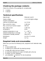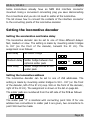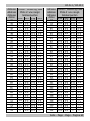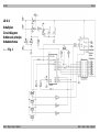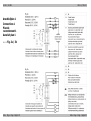
1
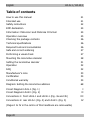
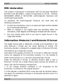
n
LD-W-1
n
Lokdecoder für Wechselstrommotoren
Motorola-Format
n
Locomotive Decoder for AC engines
Motorola-Format
n
Décodeur pour locomotive avec moteur alternatif
Format-Motorola
n
Locdecoder voor wisselstroommotoren
Motorola-format
n
Art.-Nr. 22-01-015 C 21 27 00
n
n
n
n
LD-G-1
n
Anleitung
Lokdecoder für Gleichstrommotoren
Motorola-Format
n
Manual
Locomotive Decoder for DC engines
Motorola-Format
n
Mode d´emploi
Décodeur pour locomotive avec moteur continu
Format-Motorola
n
Handleiding
Locdecoder voor gelijkstroommotoren
Motorola-format
n
Art.-Nr. 22-01-016 C 21 27 96
n
© 08/2001 Tams Elektronik GmbH
Alle Rechte, insbesondere das Recht der
Vervielfältigung und Verbreitung sowie der
Übersetzung vorbehalten. Vervielfältigungen
und Reproduktionen in jeglicher Form
bedürfen der schriftlichen Genehmigung
durch die Tams Elektronik GmbH.
Technische Änderungen vorbehalten.
© 08/2001 Tams Elektronik GmbH
All rights reserved. No part of this
publication
may
be
reproduced
or
transmitted in any form or by any means,
electronic
or
mechanical,
including
photocopying, without prior permission in
writing from Tams Elektronik GmbH.
Subject to technical modification.
© 08/2001 Tams Elektronik GmbH
Tout droits réservés, en particulier les droits
de reproduction et de diffusion ainsi que le
traduction.
Toute
duplication
ou
reproduction sous quelque forme que ce soit
nécessite l´accord écrit de la societé Tams
Elektronik GmbH.
Sous réserve de modifications techniques.
© 08/2001 Tams Elektronik GmbH
Alle rechten voorbehouden. Niets uit deze
publicatie mag worden vermenigvuldigd
opgeslagen of openbaar gemaakt, zonder
voorafgaande schriftelijke toestemming van
Tams Elektronik GmbH.
Technische wijzigingen voorbehouden.
n
n
n
n
Deutsch
n
English
20
n
Français
35
n
Nederlands
51
n
n
n
n
n
n
n
n
n
n
n
n
n
3
English
LD-G-1 / LD-W-1
Table of contents
How to use this manual
21
Intended use
21
Safety instructions
22
EMC declaration
24
Information: Motorola I and Motorola II format
24
Operation overview
25
Checking the package contents
26
Technical specifications
26
Required tools and consumables
26
Safe and correct soldering
27
Performing a visual check
27
Mounting the locomotive decoder
28
Setting the locomotive decoder
31
Operation
32
FAQ
32
Manufacturer's note
33
Certification
34
Conditional warranty
34
Diagram: Setting the locomotive address
68
Circuit Diagram LD-G-1 (Fig. 1)
Circuit Diagram LD-W-1 (Fig. 2)
I
II
Connections 1: front LD-G-1 and LD-W-1 (Fig. 3a and 3b)
III
Connections 2: rear LD-G-1 (Fig. 4) and LD-W-1 (Fig. 5)
IV
(Pages I to IV in the centre of this handbook are removeable)
Page 20
LD-G-1 / LD-W-1
English
How to use this manual
If you have no specialist technical training, this manual gives step-bystep instructions for safe and correct fitting of the module, and
operation. Before you start, we advise you to read the whole manual,
particularly the chapter on safety instructions and the FAQ chapter. You
will then know where to take care and how to prevent mistakes which
take a lot of effort to correct.
Keep this manual safely so that you can solve problems in the future. If
you pass the kit on to another person, please pass on the manual with
it.
Intended use
!
Caution:
Integrated circuits are very sensitive to static electricity. Do not touch
components without first discharging yourself. Touching a radiator or
other grounded metal part will discharge you.
The module can be used according to the specifications of this manual.
It is designed for the mounting in a model railway locomotive with d.c.
motor (LD-G-1) resp. a.c. motor (LD-W-1).
It evaluates the Motorola format data sent by the digital central unit to
its address. The decoder controls the vehicle performance (velocity,
direction of travel, acceleration), switches the lighting and four further
optional functions.
The module is not suitable for children under the age of 14.
Reading, understanding and following the instructions in this manual
are mandatory for the user.
Any other use of the kit is inappropriate and invalidates any guarantees.
Page 21
English
LD-G-1 / LD-W-1
Safety instructions
Mechanical hazards
Cut wires can have sharp ends and can cause serious injuries. Watch
out for sharp edges when you pick up the PCB.
Visibly damaged parts can cause unpredictable danger. Do not use
damaged parts: recycle and replace them with new ones.
Electrical hazards
§ Do not touch powered, live components.
§ Do not touch conducting components which are live due to
malfunction.
Avoid short circuits.
Do not connect the circuit to a higher voltage than designed.
Impermissibly high humidity.
Condensation building up can cause serious injury due to electrical
shock.
Take the following precautions to prevent this danger:
§ Never perform wiring on a powered module.
§ Only use low power for this module as described in this manual and
only use certified transformers.
§ Connect transformers and soldering stations only in approved mains
sockets installed by an authorised electrician.
§ Observe cable diameter requirements.
§ Assembling the kit should only be done in closed, clean, dry rooms.
Beware of humidity.
§ If the humidity in the room is too high, please do not start working
until after a minimum of 2 hours of acclimatisation.
§ Use only original spare parts if you have to repair the kit or the
ready-built module.
§
§
§
§
Page 22
LD-G-1 / LD-W-1
English
Fire risk
Touching flammable material with a hot soldering iron can cause lifethreatening fire, burns and toxic smoke. Connect your soldering iron or
soldering station only when actually needed. Use the correct soldering
iron or station and never leave a hot soldering iron or station
unattended.
Thermal danger
A hot soldering iron or liquid solder accidentally touching your skin can
cause skin burns. As a precaution:
§
§
§
§
use a heat-resistant mat during soldering,
always put the hot soldering iron in the soldering iron stand,
point the soldering iron tip carefully when soldering, and
remove liquid solder with a thick wet rag or wet sponge.
Dangerous environments
A working area that is too small or cramped is unsuitable and can cause
accidents, fires and injury. Prevent this by working in a clean, dry room
with enough freedom of movement.
Other dangers
Children can cause any of the accidents mentioned above because they
are inattentive and not responsible enough. Children under the age of
14 should not be allowed to work with this kit or the ready-built
module.
Little children can swallow small components with sharp edges. Life
threatening! Do not allow components to reach small children.
In schools, training centres, clubs and workshops, assembly must be
supervised by qualified personnel.
In industrial institutions, health and safety regulations applying to
electronic work must be adhered to.
Page 23
English
LD-G-1 / LD-W-1
EMC declaration
This product is developed in accordance with the European standards
EN 55014 and EN 50082-1, tested corresponding to the EC - directive
89/336/EWG (EMVG of 09/11/1992, electromagnetic tolerance) and
meets legal requirements.
To guarantee the electromagnetic tolerance you must take the
following precautions:
§ Connect the transformer only to an approved mains socket installed
by an authorised electrician.
§ Make no changes to the original parts and accurately follow the
instructions, circuit diagram and PCB layout included with this manual.
§ Use only original spare parts if you have to repair the kit or the
ready-built module.
Information: Motorola I and Motorola II format
The digital driving data is differently encoded and transmitted in the
(old) Motorola I format and the (new) Motorola II format. The
locomotive decoder is designed to evaluate data in Motorola II format.
This limits its use in Motorola I format.
Since data of the auxiliary functions F1 to F4 sent in Motorola I Format
cannot be evaluated by the locomotive decoder, it is not possible to
switch these functions on or off when using Motorola I format.
Unlike the Motorola II format, no absolute direction data is sent in
Motorola I format, but a single driving signal reverses the direction of
travel. This has the following consequences:
1. If the change direction command is not recognized by the
locomotive, it continues in the original direction.
2. If the decoder is switched off for some time and the direction data is
not saved, the locomotive continues in its favourite direction when it is
switched on again.
Page 24
LD-G-1 / LD-W-1
English
Operation overview
The decoder is designed for operation in Motorola I or II format and
can be adjusted to one of 255 adresses. It evaluates the digital data
sent by the central unit to its address and transmitts it to the
locomotive.
Function speed level and direction of motion
The speed level set at the central unit and the change-direction
command are transmitted to the locomotive by the decoder. At a
direction change the existing direction of travel is not saved, so the
locomotive continues in Motorola I format in its preferred direction after
the decoder has been off for some time.
Acceleration and brake delay
Three variants of acceleration and brake delay are available: fast,
medium and slow. By attaching solder bridges one of the three variants
can be fixed.
Function lighting
The lighting can be switched on and off according to the direction of
travel from the central unit via the function "function". In addition,
another optional accessory (e.g. cab lighting, noise module) can be
switched on and off according to the direction of travel.
Auxiliary functions in Motorola II format
The auxiliary functions F1 to F4 can be switched from the central unit.
They are available to control optional accessories (e.g. smoke
generator, cab lighting, noise module).
Restrictions in Motorola I format
The auxiliary functions F1 to F4 are not available in Motorola I format.
It is possible to control one accessory via the function "function"
according to the direction of travel.
Page 25
English
LD-G-1 / LD-W-1
Checking the package contents
Check the contents of the package for completeness:
§ 1 module
§ 1 manual
Technical specifications
Data format
Supply voltage
Current consumption
(without connected loads)
Max. current for motor
Max. current per function output
Max. total current
Protected to
Ambient temperature in use
Ambient temperature in storage
Comparative humidity allowed
Dimensions
Weight
Motorola I and II
12-22 Volt digital voltage
ca. 10 mA
1.000 mA
500 mA
1.500 mA
IP 00
0 - + 60° C
-10 - + 80° C
max. 85 %
ca. 25 x 17 x 8 mm
ca. 5 g
Required tools and consumables
Make sure you have the following tools, equipment and materials ready
for use:
§
§
§
§
§
§
a heat-resistant mat
a soldering iron stand with tip-cleaning sponge
a small side cutter and wire stripper
an electronic soldering iron (max. 30 Watt) with a fine tip
tin solder (0,5 mm. diameter)
wire (diameter: > 0,08 mm² for all connections)
Page 26
LD-G-1 / LD-W-1
English
Safe and correct soldering
!
Caution:
Incorrect soldering can cause fires (through excessive heat). Avoid this
danger by reading the chapter Safety instructions again and
following the directions given.
If you have had training in soldering you can skip this chapter.
§ When soldering electronic circuits never use soldering-water or
soldering grease. They contain acids that can corrode components
and copper tracks.
§ Only use tin solder SN 60 Pb (i.e. 60 % tin, 40 % lead) with rosinbased flux.
§ Solder fast: long soldering can destroy components and copper
tracks, and damages through plated holes.
§ Use a small soldering iron with max. 30 Watt. Keep the soldering tip
clean so the heat of the soldering iron is applied to the solder point
effectively.
§ Apply the soldering tip to the soldering spot in such a way that the
part and the soldering spot are heated at the same time.
Simultaneously add solder (not too much). As soon as the solder
becomes liquid take it away. Hold the soldering tip at the spot for a
few seconds so that the tin solder finds its way, then remove the
soldering iron.
§ Do not move the component for about 5 seconds after soldering. A
glossy and perfect soldering spot should remain.
§ To make a good soldering joint you must use a clean and
unoxidised soldering tip. Clean the soldering tip with a damp piece
of cloth, a damp sponge or a piece of silicon cloth.
Performing a visual check
Damaged materials can cause injury. Parts damaged during transit can
also be dangerous.Check the module for damage, missing parts or poor
soldering. If you find damage, return the module for exchange.
Page 27
English
LD-G-1 / LD-W-1
Mounting the locomotive decoder
Open the locomotive housing. Locate the position for the decoder.
Disconnect the motor from the rail current collector respectively the
change-over switch from the motor and rails if you have a locomotive
with electronic change-over switch.
!
Caution:
The interference suppression devices mounted to the motor or the
connecting wire must not be removed! Motor and interference
suppression devices are one unit. If even one part is removed, it can
cause extreme interference!
Connecting the LD-G-1
Follow the connections diagrams (fig. 4)! Solder the connections to the
rails at points X1 and X2 (rear of the locomotive decoder) and the
connections to the motor at the points X11 and X12 (rear of the
locomotive decoder).
The connection to the rails is optional, but you must observe polarity
when connecting the motor.
Tip: In three rail systems, connect the centre conductor to X2. The
locomotive response to control data improves, compared with
connection to X1.
Connecting the LD-W-1
Follow the connections diagrams (fig. 5)! Solder the connections to the
rails at points X1 and X2 (rear of the locomotive decoder) and the
connections to the motor at the points X11, X12 and X19 (rear of the
locomotive decoder).
!
Caution:
The connections to the rails and motor must be made as shown in the
diagram "connections"! Otherwise the locomotive decoder will not
respond to the control data sent by the central unit.
Page 28
LD-G-1 / LD-W-1
English
Connecting the lighting and other accessories
Follow the connections diagrams (fig. 3a and 3b)!
Disconnect any existing diodes in the leads to the lamps. Connect the
lamps for forward motion to X4 and the lamps for reverse to point X5
(front of the locomotive decoder). If the lamps are already connected
with one side to locomotive ground, you must solder in a diode
between the decoder and the lamp (see fig. 3a) or you must connect
the second side of the lamps according to fig. 3b to the return
conductor (point X3 on the front of the decoder).
Connect other accessories (e.g. smoke generator, cab lighting), which are
switched by the functions F1 to F4, to the points X7 to X10 (front of the
decoder). You can connect the second side of the accessories either to
the return conductor (point X3) or to locomotive ground. If connecting
the accessory to locomotive ground you must solder in a diode.
!
Caution:
The return conductor for all functions (point X3) must under no
circumstances be connected to locomotive ground. Possible short
circuit! The locomotive decoder will be damaged in operation.
Tip: If the second side of the lamps is connected to locomotive ground
the lamps often flicker in operation. You can avoid the flickering of the
lamps if you connect the second side to the return conductor (point X3)
instead of locomotive ground.
!
Caution:
If you connect the loads to the return conductor for all functions (point
X3), the load must be insulated. The loads must not make contact with
metal parts of the locomotive. Possible short circuit! The locomotive
decoder will be damaged in operation.
Connecting the LEDs
The function outputs of the locomotive decoder switch against decoder
ground. For that reason you must connect the cathode (-) of the LED to
the output of the relevant function.
Page 29
English
!
LD-G-1 / LD-W-1
Caution:
If you use light-emitting diodes (LEDs) you must always operate them
via a series resistor.
LEDs are available in many different models. There are LEDs with 2-5
mA, but also LEDs with 15-30 mA power consumption. The series
resistor limits the current flow of the LED and will need to be calculated
for each model. Ask for the max current rating when buying your LEDs.
You can connect several LEDs in parallel to each output. In this case
every LED must have a series resistor of its own. If you connect several
LEDs to one output in series, only one series resistor is needed. The
number of LEDs connected in series to one output depends on the
digital voltage.
You can determine the number of the LEDs that can be connected in
series to one output from the following formula:
(number of LEDs + 2) x 1,5 < digital voltage
Fixing the locomotive decoder
After completing all connections fix the locomotive decoder with doublesided adhesive tape, for example.
Using an NEM 652 interface connector
Contact
1
2
3
4
5
6
7
8
Page 30
Connection
Motor connection 1
Lighting back (-)
Not used or F1
Power supply left
Motor connection 2
Lighting front (-)
Common conductor
for all functions (+)
Power supply right
Colour of
cable
orange
yellow
green
black
grey
white
blue
Connecting points
X11
X5
X7
X1
X12
X4
X3
red
X2
LD-G-1 / LD-W-1
English
Some locomotives already have an NEM 652 interface connector
mounted. Using a convenient connecting plug you save disconnecting
the connections and you do not need to solder at the locomotive.
The list shows how to connect the contacts of the interface connector
to the connecting points of the locomotive decoder.
Setting the locomotive decoder
Setting the acceleration and brake delay
The locomotive decoder can be set to one of three different delays:
fast, medium or slow. The setting is made by mounting solder bridges
to X17 (on the front of the decoder, beneath the IC U1). The
assignment is as follows:
Fast delay
No solder bridge
Medium delay Solder bridge between two
optional solder pads
Slow delay
Solder bridge across all the
solder pads
or
Setting the locomotive address
The locomotive decoder can be set to one of 255 addresses. The
setting is made by mounting solder bridges to X13 - X17 (on the front
of the decoder, left of the IC U1) resp. X18 on the front of the decoder,
right of the IC U1). The assignment is shown in the list on page 68.
The solder pads are numbered from the left side of the PCB as follows:
1
2
3
The solder pad "4" is identical with connecting point X18. If for one
address two connections to solder pad 4 are given, two connections to
point X18 must be made.
Page 31
English
!
LD-G-1 / LD-W-1
Caution:
Use a soldering iron with a small tapered point and max. 30 Watt to
make the solder bridges. Take special care to avoid short circuits. If
necessary, check the solder bridges with a magnifiying glass to make
sure that the solder bridges are closed correctly and solder has not
short-circuited adjacent components or connections.
Operation
Emergency stop during active acceleration and brake delay
An emergency stop during acceleration and brake delay can be
performed from the central unit by changing the direction of travel.
Improvement of the driving characteristics
Locomotives with especially high current consumption or track sections
with bad contacts (e.g. some types of points) may give an
unsatisfactory performance after the mounting of the locomotive
decoder. You can improve the locomotive performance by soldering a
capacitor 220 µF / > 25 V in parallel to the capacitor C2 (rear of the
locomotive decoder, see fig. 4 or 5).
The settings cannot be saved by the decoder and are lost after a power
supply interruption of a certain length. When the interruption is only short,
the capacitor C1 maintains the voltage and the settings are kept. You can
lengthen this period of time by soldering a capacitor 47 µF / > 6,3 V in
parallel to the capacitor C1 (rear of the locomotive decoder, see fig. 4 or 5).
FAQ
§ Parts are getting too hot and/or start to smoke.
!
Disconnect the system from the mains immediately!
Possible cause: one or more connections are soldered incorrectly.
à Check the connections.
Page 32
LD-G-1 / LD-W-1
English
Possible cause: The connection of the motor is connected to
locomotive ground.
à Disconnect the connection from locomotive ground.
§ The locomotive lighting does not correspond to its direction of travel.
Possible cause: The forward and backward light connections have
been exchanged.
à Check the connections.
Possible cause: The connections of the motor to the points X11 and
X12 have been exchanged.
à Exchange the connections.
§ A lamp flickers (this is not a defect).
Possible cause: The lamp is connected with one side to locomotive
ground.
à If you do not want the lamp to flicker, disconnect it from
locomotive ground, insulate it and connect it to the return
conductor (point X3).
§ The locomotive does not run.
Possible cause: The locomotive address is not set correctly.
à Check the solder bridges (if necessary with a magnifiying glass).
Possible cause (locomotive with LD-W-1): The connections to the
rails (points X1 and X2) have been exchanged.
à Exchange the connections.
If you cannot find the problem, please return the decoder for repair
(address on the cover page).
Manufacturer's note
According to DIN VDE 0869, the person who builds this kit or brings the
circuit into operation is the manufacturer of the product. If he sells the
product to another person he is responsible for passing on all the
relevant papers. Domestic appliances assembled from a kit are deemed
industrial products and must comply with health and safety regulations.
Page 33
English
LD-G-1 / LD-W-1
Certification
This product conforms with the EC- directive 89/336/EWG on
electromagnetic radiation and is therefore CE certified.
Conditional warranty
This product is guaranteed for two years. The warranty includes free
repair if the problem is due to material failure or incorrect assembly of
the module by us. We guarantee the quality of the components.
Other claims are excluded. By law, we are not responsible for damages
or secondary damages in connection with this product. We retain the
right to repair, make improvements, supply spare parts or return the
purchase price.
The following invalidate the warranty:
§ using an unsuitable soldering iron, solder containing liquid acids or
similar,
§ if damage is caused by not following the instructions in this manual
or the circuit diagram,
§ if the circuit has been altered and repair attempts have failed,
§ if arbitrary changes in the circuit are made,
§ if parts are stored incorrectly and if the wires to the switches, the
§
§
§
§
§
§
§
power resistors, etc. are made incorrectly,
if the copper tracks or soldering points are damaged,
if parts are placed incorrectly or the circuit is connected incorrectly,
if damage occurs due to an overload of the circuit,
if the wrong power or current is connected,
if damaged by other persons,
if damaged by the wrong use or abuse of the circuit,
if parts are damaged due to static because they were touched
before a discharge is performed.
Page 34
LD-G-1 / LD-W-1
Einstellung der Adresse / Adjusting the address
Réglage de l’adresse / Instellen van het adres
Beispiel:
Einstellung der Adresse "107"
Example:
Adjusting the address "107"
Exemple:
Réglage de l´adresse "107"
Voorbeeld:
Instellen van adres "107"
Adresse Lötfeld - Soldering field
Address
Plots d´une rangé
Adresse
Soldeerpunten
Adres X14 X13 X16 X15
1
2-3 2-4 2-3 2-4
2
2-3 2-4 2-4 2-4
3
2-4 2-3 2-4 2-3
4
2-3 2-3 2-3 2-3
5
2-3 2-3 2-4 2-3
6
2-4 2-4 2-4 2-3
7
2-3 2-4 2-3 2-3
8
2-3 2-4 2-4 2-3
9
1-2 2-4 1-2 2-4
10
-2-4
-2-4
11
-2-4 1-2 2-4
12
1-2 2-3 1-2 2-3
13
-2-3
-2-3
14
-2-3 1-2 2-3
15
1-2 2-4 1-2 2-3
16
-2-4
-2-3
17
-2-4 1-2 2-3
18
1-2 2-4 2-4 2-4
19
-2-4 2-3 2-4
20
-2-4 2-4 2-4
Seite - Page - Page - Pagina 68
Adresse Lötfeld - Soldering field
Address
Plots d´une rangé
Adresse
Soldeerpunten
Adres X14 X13 X16 X15
21
1-2 2-3 2-4 2-3
22
-2-3 2-3 2-3
23
-2-3 2-4 2-3
24
1-2 2-4 2-4 2-3
25
-2-4 2-3 2-3
26
-2-4 2-4 2-3
27
2-4 1-2 2-4 1-2
28
2-3 1-2 2-3 1-2
29
2-3 1-2 2-4 1-2
30
2-4
-2-4
-31
2-3
-2-3
-32
2-3
-2-4
-33
2-4 1-2 2-4
-34
2-3 1-2 2-3
-35
2-3 1-2 2-4
-36
1-2 1-2 1-2 1-2
37
-1-2
-1-2
38
-1-2 1-2 1-2
39
1-2
-1-2
-40
-----
LD-G-1 / LD-W-1
Adresse Lötfeld - Soldering field
Address
Plots d´une rangé
Adresse
Soldeerpunten
Adres X14 X13 X16 X15
41
--1-2
-42
1-2 1-2 1-2
-43
-1-2
--44
-1-2 1-2
-45
1-2 1-2 2-4 1-2
46
-1-2 2-3 1-2
47
-1-2 2-4 1-2
48
1-2
-2-4
-49
--2-3
-50
--2-4
-51
1-2 1-2 2-4
-52
-1-2 2-3
-53
-1-2 2-4
-54
2-4 2-4 2-4 1-2
55
2-3 2-4 2-3 1-2
56
2-3 2-4 2-4 1-2
57
2-4 2-3 2-4
-58
2-3 2-3 2-3
-59
2-3 2-3 2-4
-60
2-4 2-4 2-4
-61
2-3 2-4 2-3
-62
2-3 2-4 2-4
-63
1-2 2-4 1-2 1-2
64
-2-4
-1-2
65
-2-4 1-2 1-2
66
1-2 2-3 1-2
-67
-2-3
--68
-2-3 1-2
-69
1-2 2-4 1-2
-70
-2-4
--71
-2-4 1-2
-72
1-2 2-4 2-4 1-2
73
-2-4 2-3 1-2
74
-2-4 2-4 1-2
75
1-2 2-3 2-4
-76
-2-3 2-3
--
Adresse Lötfeld - Soldering field
Address
Plots d´une rangé
Adresse
Soldeerpunten
Adres X14 X13 X16 X15
77
-2-3 2-4
-78
1-2 2-4 2-4
-79
-2-4 2-3
-80
2-4 2-4 2-4 2-4
81
2-4 2-4 2-3 2-4
82
2-4 2-4 2-3 2-3
83
2-3
-1-2 1-2
84
2-4 2-3 2-3 2-3
85
1-2 2-4 2-3 2-4
86
1-2 2-4 2-3 2-3
87
1-2 2-3 2-3 2-4
88
1-2 2-3 2-3 2-3
89
2-4 2-4
-2-4
90
2-4 2-4
-2-3
91
2-4 2-3
-2-4
92
2-4 2-3
-2-3
93
1-2 2-4
-2-4
94
1-2 2-4
-2-3
95
1-2 2-3
-2-4
96
1-2 2-3
-2-3
97
2-4 2-4 2-3 1-2
98
2-4 2-4 2-3
-99
2-4 2-3 2-3 1-2
100
2-4 2-3 2-3
-101
1-2 2-4 2-3 1-2
102
1-2 2-4 2-3
-103
1-2 2-3 2-3 1-2
104
1-2 2-3 2-3
-105
2-4 2-4
-1-2
106
2-4 2-4
--107
2-4 2-3
-1-2
108
2-4 2-3
--109
1-2 2-4
-1-2
110
1-2 2-4
--111
1-2 2-3
-1-2
112
1-2 2-3
--Seite - Page - Page - Pagina 69
LD-G-1 / LD-W-1
Adresse Lötfeld - Soldering field
Address
Plots d´une rangé
Adresse
Soldeerpunten
Adres X14 X13 X16 X15
113
2-4 1-2 2-3 2-4
114
2-4 1-2 2-3 2-3
115
2-4
-2-3 2-4
116
2-4
-2-3 2-3
117
1-2 1-2 2-3 2-4
118
1-2 1-2 2-3 2-3
119
1-2
-2-3 2-4
120
1-2
-2-3 2-3
121
2-4 1-2
-2-4
122
2-4 1-2
-2-3
123
--1-2 1-2
124
2-4
--2-3
125
1-2 1-2
-2-4
126
1-2 1-2
-2-3
127
1-2
--2-4
128
1-2
--2-3
129
2-4 1-2 2-3 1-2
130
2-4 1-2 2-3
-131
2-4
-2-3 1-2
132
2-4
-2-3
-133
1-2 1-2 2-3 1-2
134
1-2 1-2 2-3
-135
1-2
-2-3 1-2
136
1-2
-2-3
-137
2-4 1-2
-1-2
138
2-4 1-2
--139
2-4
--1-2
140
2-4
---141
1-2 1-2
-1-2
142
1-2 1-2
--143
1-2
--1-2
144
1-2
---145
2-4 2-3 2-4 2-4
146
1-2 2-3 2-4 2-4
147
2-4 2-3 1-2 2-4
148
1-2 2-3 1-2 2-4
Seite - Page - Page - Pagina 70
Adresse Lötfeld - Soldering field
Address
Plots d´une rangé
Adresse
Soldeerpunten
Adres X14 X13 X16 X15
149
2-4 2-3 2-4 1-2
150
1-2 2-3 2-4 1-2
151
2-4 2-3 1-2 1-2
152
1-2 2-3 1-2 1-2
153
2-4
-2-4 2-4
154
1-2
-2-4 2-4
155
2-4
-1-2 2-4
156
1-2
-1-2 2-4
157
2-4
-2-4 1-2
158
1-2
-2-4 1-2
159
2-4
-1-2 1-2
160
1-2
-1-2 1-2
161
2-3 2-3 2-3 2-4
162
-2-3 2-3 2-4
163
2-3 2-3
-2-4
164
-2-3
-2-4
165
2-3 2-3 2-3 1-2
166
-2-3 2-3 1-2
167
2-3 2-3
-1-2
168
-2-3
-1-2
169
2-3
-2-3 2-4
170
--2-3 2-4
171
2-3
--2-4
172
---2-4
173
2-3
-2-3 1-2
174
--2-3 1-2
175
2-3
--1-2
176
---1-2
177
2-3 2-3 2-4 2-4
178
-2-3 2-4 2-4
179
2-3 2-3 1-2 2-4
180
-2-3 1-2 2-4
181
2-3 2-3 2-4 1-2
182
-2-3 2-4 1-2
183
2-3 2-3 1-2 1-2
184
-2-3 1-2 1-2
LD-G-1 / LD-W-1
Adresse Lötfeld - Soldering field
Address
Plots d´une rangé
Adresse
Soldeerpunten
Adres X14 X13 X16 X15
185
2-3
-2-4 2-4
186
--2-4 2-4
187
2-3
-1-2 2-4
188
--1-2 2-4
189
2-3
-2-4 1-2
190
--2-4 1-2
191
2-4 2-3 2-3 2-4
192
2-4
--2-4
193
2-4 2-4 1-2 2-4
194
2-4 2-4 1-2 1-2
195
2-4 1-2 1-2 2-4
196
2-4 1-2 1-2 1-2
197
2-3 2-4
-2-4
198
2-3 2-4
-1-2
199
2-3 1-2
-2-4
200
2-3 1-2
-1-2
201
2-3 2-4 1-2 2-4
202
2-3 2-4 1-2 1-2
203
2-3 1-2 1-2 2-4
204
2-3 1-2 1-2 1-2
205
2-4 2-3 1-2 2-3
206
2-4 2-3 1-2
-207
2-4
-1-2 2-3
208
2-4 1-2 1-2
-209
2-3 2-3
-2-3
210
2-3 2-3
--211
2-3
--2-3
212
2-3
---213
2-3 2-3 1-2 2-3
214
2-3 2-3 1-2
-215
2-3
-1-2 2-3
216
2-3
-1-2
-217
2-4 2-4 1-2 2-3
218
2-4 2-4 1-2
-219
2-4 1-2 1-2 2-3
220
2-4 1-2 1-2
--
Adresse Lötfeld - Soldering field
Address
Plots d´une rangé
Adresse
Soldeerpunten
Adres X14 X13 X16 X15
221
2-3 2-4
-2-3
222
2-3 2-4
--223
2-3 1-2
-2-3
224
2-3 1-2
--225
2-3 2-4 1-2 2-3
226
2-3 2-4 1-2
-227
2-3 1-2 1-2 2-3
228
2-3 1-2 1-2
-229
2-4 1-2 2-4 2-4
230
2-3 1-2 2-3 2-4
231
2-3 1-2 2-4 2-4
232
2-4
-2-4 2-3
233
2-3
-2-3 2-3
234
2-3
-2-4 2-3
235
2-4 1-2 2-4 2-3
236
2-3 1-2 2-3 2-3
237
2-3 1-2 2-4 2-3
238
1-2 1-2 1-2 2-4
239
-1-2
-2-4
240
-1-2 1-2 2-4
241
1-2
-1-2 2-3
242
---2-3
243
--1-2 2-3
244
1-2 1-2 1-2 2-3
245
-1-2
-2-3
246
-1-2 1-2 2-3
247
1-2 1-2 2-4 2-4
248
-1-2 2-3 2-4
249
-1-2 2-4 2-4
250
1-2
-2-4 2-3
251
--2-3 2-3
252
--2-4 2-3
253
1-2 1-2 2-4 2-3
254
-1-2 2-3 2-3
255
-1-2 2-4 2-3
Seite - Page - Page - Pagina 71
LD-G-1
LD-G-1
LD-G-1
Schaltplan
Circuit diagram
Schéma de principe
Schakelschema
n n n
Fig. 1
Seite - Page - Page - Pagina I
Ausgänge
Outputs
Sorties
Uitgangen
Seite - Page - Page - Pagina I
LD-W-1
LD-W-1
LD-W-1
Schaltplan
Circuit diagram
Schéma de principe
Schakelschema
n n n
Fig. 2
Seite - Page - Page - Pagina II
Ausgänge
Outputs
Sorties
Uitgangen
Seite - Page - Page - Pagina II
LD-G-1 / LD-W-1
LD-G-1 / LD-W-1
Anschlußplan 1
Connections 1
Plan de
raccordement 1
Aansluit plan 1
n n n
Fig. 3a / 3b
Seite - Page - Page - Pagina III
Seite - Page - Page - Pagina III
LD-G-1 / LD-W-1
LD-G-1 / LD-W-1
Anschlußplan 2
Connections 2
Plan de
raccordement 2
Aansluit plan 2
n n n
Fig. 4 / 5
Seite - Page - Page - Pagina IV
Seite - Page - Page - Pagina IV
n
n
n
Aktuelle Informationen und Tipps:
Information and tips:
Informations et conseils:
Actuele informatie en tips:
http://www.tams-online.de
n
n
n
n
n
n
Garantie und Service:
Warranty and service:
Garantie et service:
Garantie en service:
n
n
Tams Elektronik GmbH
Sievertstraße 22
D-30625 Hannover
fon: 0049 (0)511 / 55 60 60
fax: 0049 (0)511 / 55 61 61
e-mail: [email protected]
n
n