1
Ñ
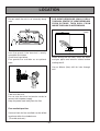
Energysaver Heater
RHFE-1004FTR
Customer
page 2
Installer
page 18
This appliance shall be installed in accordance with:
・Manufacturer's Instructions
・Local Authority Building Codes
・NZS 5261 Installation Code for Gas Burning Equipment
・Any other relevant Statutory Regulation
This appliance must be installed, serviced and removed by an authorised
person.
CONTENTS
Features of your 1004 FTR ……………………………………………………………………………2
Getting to know your New 1004 FTR …………………………………………………………………3
Control Panel Layout ……………………………………………………………………………………4
Important Points …………………………………………………………………………………………5
Customers Operating Information
How to Operate the Heater ……………………………………………………………………………7
Adjusting Temperature …………………………………………………………………………………8
Economy Mode …………………………………………………………………………………………9
Function Lock …………………………………………………………………………………………10
Override Function ………………………………………………………………………………………11
Setting Clock ……………………………………………………………………………………………12
Programming the ON/OFF Timer(s) …………………………………………………………………13
Operating the Heater Timer(s) ………………………………………………………………………14
Pre-Heat Function………………………………………………………………………………………15
Other Operating Information …………………………………………………………………………16
Remote Control …………………………………………………………………………………………17
Installation
Location …………………………………………………………………………………………………18
Installation Instructions ………………………………………………………………………………21
Sleeve and Manifold Installation………………………………………………………………………22
Fitting Unit ………………………………………………………………………………………………24
Testing …………………………………………………………………………………………………25
Installation Check ………………………………………………………………………………………26
Care of your 1004 FTR ………………………………………………………………………………27
Pre-Service Check ……………………………………………………………………………………28
Error Messages …………………………………………………………………………………………29
Safety Devices …………………………………………………………………………………………30
Product Specifications
Dimensions ……………………………………………………………………………………………31
Wiring Diagram …………………………………………………………………………………………32
Block Diagram …………………………………………………………………………………………32
Guarantee ………………………………………………………………………………………………34
Specifications …………………………………………………………………………………………35
Service Contact Points…………………………………………………………………………………35
–1–
FEATURES OF YOUR 1004 FTR
Push button ignition : Only one touch of the ON / OFF button is required to operate the heater.
Dual Timer : The dual timer allows you to program the heater to come on for two separate periods
each day, usually one period in the morning and one period in the evening. The dual timer feature
means that you can set and forget your heater. It will turn itself ON and OFF at the times you
have programmed until you cancel the timer program.
7 step automatic heat control with electronic thermostat. The fan is also controlled by the
thermostat.
Pre-Heat : This function will automatically operate the heater within one-hour prior to the
programmed time of the timer in order to heat a room to the pre-set temperature by the
programmed time.
Economy mode : An energy saving feature that reduces the room temperature by 3℃ over a 90
minute interval.
Memory : The micro-computer records selected pre-set temperatures, the times programmed into
Timers as well as operating the Economy and Pre-heat modes to maintain comfort levels. Even if
the power cord is pulled out of the power point, the next time the unit is operated, there will be no
need to re-program the Timer times (only the clock will need to be re-programmed).
Override Function : This temporarily changes the heater operation from ON to OFF, or vice
versa, until the next programmed setting is reached.
Remote Control : A remote control is supplied to enable you to turn your 1004 FTR ON and OFF,
and to adjust its temperature at your convenience. The remote control also comes with its own
handy bracket for easy storage.
Lockable Control Panel Lid : The 1004 FTR has a lockable Control Panel Lid which is ideal for
commercial use. This feature is great for applications where safety is paramount or when the unit
is required to be set once and left alone. Two keys are also supplied with the unit.
Function Lock : Prevents children from altering heater settings whilst running, or from activating
the heater when turned off. This feature is utilised if the Control Panel Lid is unlocked.
Heater Filter Indicator : When the heater filter becomes covered with dust and the temperature
inside the appliance rises, the heater filter indicator will flash indicating that cleaning is necessary.
The integral humidifier tray can be filled with water as required to raise the humidity level in the
room.
Room Sealed : Air for combustion is taken from the outside and the flue product is exhausted
outside, keeping the room air clean.
–2–
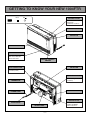
GETTING TO KNOW YOUR NEW 1004FTR
Filt er
oN
CONTROL PANEL
OPERATION/TEMPERATURE
CONTROL DISPLAY
FILTER INDICATOR
OPERATION
INDICATOR
WARM AIR OUTLET
HUMIDIFIER
OPEN THE DOOR
AND POUR WATER
INTO THE TRAY.
REMOTE CONTROL
SENSOR
GAS CONNECTION
AIR FILTER
1/2" BSP(15mm)
FLUE TERMINAL
THERMISTOR
(“A” Flue supplied as
standard)
POWER CORD
EXHAUST PIPE
RATING PLATE
PLUG 230VAC
COMBUSTION AIR
INTAKE HOSE
–3–
MODEL NUMBER,
SERIAL NUMBER,
GAS TYPE, ETC.
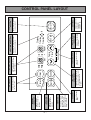
–4–
Timer 1
TIME / TEMP
ADJUSTMENT
Increases or decreases the
temperature setting as well
as changing hours or
minutes.
Selects Economy
Mode.
Override Economy
Timer 2
PM
AM
Temp
Time
Room
Locks all controls when
pressed.
FUNCTION LOCK
Indicates Function lock
is activated.
FUNCTION LOCK
INDICATOR
Set Times
Clock
Timer 1
on off
Timer 2
Indicates that clock or dual timer
programme is being set.
CLOCK ADJUSTMENT
AND TIMER INDICATORS
Function Lock
Set
Shows either the time of
day, temperatures, or error
code messages.
Selects operating mode
for Timer 1 or 2.
ECONOMY
Temporarily changes
operation from ON to
OFF or OFF to ON,
until next programmed
setting is reached.
OVERRIDE
Indicates that the
override function is
activated.
OVERRIDE
INDICATOR
Indicates that the
Economy mode is in
operation.
ECONOMY
INDICATOR
TIME / TEMP DISPLAY
ON TIMERS
Selects clock and /
or timers for
adjusting or
programming.
SET TIMES
ON / OFF
Main switch for turning
heater on and off.
HEATER ON/OFF
BUTTON
CONTROL PANEL LAYOUT
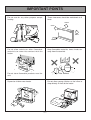
IMPORTANT POINTS
Do not use for any other purpose except
heating.
These clearances should be maintained at all
times.
250mm
50mm
50mm
1000mm
Keep flammable materials, trees shrubs etc.
away from flue terminal.
Do not allow curtains or other flammable
materials to come into contact with the
heater.
LP GAS
Do not store flammable products near the
unit.
Flue Terminal
Supervise children near heater.
Do not allow young children or the infirm to
sleep directly in front of the heater.
–5–
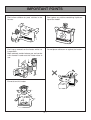
IMPORTANT POINTS
Don’t allow children to ‘post’ articles in the
louvres.
Don’t place any articles containing liquids on
top of the heater.
Don’t spray aerosols on the heater whilst it is
in operation.
Most aerosols contain butane gas and can be
a fire hazard if used near this heater when in
use.
Do not place articles on or against the heater.
Do not sit on this heater.
–6–
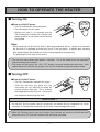
HOW TO OPERATE THE HEATER
■ Turning ON
●Press the ON/OFF button
・The ON indicator will illuminate green.
・The convection fan will rotate.
・Ignition will take 5∼ 10 seconds and the
ON / Combustion indicator will change from
green to red to let you know that the burner
has ignited.
ON / OFF
Note :
・When using the unit for the first time or after long periods of disuse, ignition may not occur
the first time it is operated as there may be air in the gas pipes. If ignition does not occur
after approximately 30 seconds the unit will cease operation automatically.
Try operating the unit again if this occurs.
・The unit may make noises after ignition / extinction. This is the inside of the unit expanding
and contracting and is normal.
・The heater will not ignite if the “ON / OFF” button is pressed straight after extinction. After
approximately 20 seconds has passed. the unit will automatically go into ignition mode.
■ Turning OFF
●Press the ON/OFF button
・The ON / Combustion indicator will go out.
・ After the indicator has gone out, the
convection fan will continue to rotate for
several minutes, then stop. This is to lower
the temperature within the unit. Do not pull
out the power cord during this time.
ON / OFF
CAUTION !
・Do not pull out the power cord or disconnect the power during combustion to cause
extinction, or straight after extinction, as this may cause damage to the unit.
・When the Function Lock is set, the Function Lock indicator will continue to illuminate even
when the unit is OFF and the Function Lock will not be cancelled.
–7–
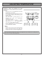
ADJUSTING TEMPERATURE
Displaying, setting and adjusting the room
temperature can only be done when the heater is
operating.
・When the unit is first operated, the room
temperature is set at 22℃.
・Set the desired room temperature with the
up and down buttons while looking at the
display section.
・The “Set Temp” can be set to “L” or
between “16” ∼ “26” , or “H” (continuous
combustion on High) .
・The “Room Temp” will display “L” (when
lower than 1℃), “1” ∼ “30” (at intervals of
1℃), or “H” (when higher than 30℃).
・Once a temperature is set, it will be stored in
the microcomputer's memory.
AM
PM
Set
Room
Temp
Time
Clock
Timer 1
on off
Timer 2
Set Times
Function Lock
Press to lower
the temperature
Press to raise
the temperature
Note :
・Rooms may not arrive at the set temperature
due to the construction of the room, the
location of the unit, or external temperatures.
If the heater does not ignite then the pre-set temperature may not be set to a setting which is
higher than the actual room temperature.
–8–
O
ECONOMY MODE
The Economy Mode, when selected, has the ability to reduce gas consumption and ultimately
save energy. Once a room has reached the desired temperature, the unit will automatically begin
reducing the set temperature gradually. This reduction is normally not noticeable, however, it is
purely your choice whether to select this mode.
How it works :
・After a room reaches the set temperature, the set room temperature will decrease 3 times
automatically, each time, dropping by a maximum of 1℃ in 30 minute blocks. From the
second time onwards, the comfort control will automatically operate. (The comfort control
alters combustion and fan speed more frequently to counteract the feeling of cold air. )
・The Economy indicator will illuminate to let you know that the Economy Function is selected.
・The Economy function will not operate when the set room temperature is less than 16℃ or
above 26℃.
・When the Economy function is operating, the current room temperature may be shown as
being lower than the set room temperature, however, this is normal.
Set
Room
Temp
Max. 1℃
Max. 1℃
Max. 1℃
30min
30min
30min
Comfort Control
"Economy" indicator illuminates
Timer 2
Timer 1
AM
PM
Set
Override Economy
Room
T
T
Temp
Time
Function Lock
–9–
FUNCTION LOCK
The Function Lock will help to prevent accidental operation as well as small children from
altering the heater settings.
1
Timer 1
The Function Lock can be operated either when the
heater is running, or in the “stand by” mode, by
pressing the up and down buttons simultaneously.
The Function is activated and the Function Lock
indicator will glow.
2
PM
Set
Room
Temp
Time
Economy
Clock
Timer 1
on off
Timer 2
Set Times
AM
PM
Set
Economy
Room
Temp
Time
Clock
Timer 1
on off
Timer 2
Set Times
Function Lock
When the Function lock is activated during normal operation all heater controls other than the
OFF switch will be locked. Deactivating the lock releases the controls. If the lock is activated
whilst the heater is turned OFF, then all heater functions will be locked. If the heater is
turned OFF whilst the Function lock is activated, it cannot be turned ON again until the lock is
deactivated.
– 10 –
O
Function Lock
Timer 1
To de-activate the Function Lock, simply press
both arrow buttons simultaneously for 2 seconds
and the Function Lock indicator will go out. The
lock can be de-activated at any time in this way.
AM
O
OVERRIDE FUNCTION
This function is used to manually override the current operation of the heater. For example ; if
the heater is in standby mode (ie. between finishing time and starting time of a Timer) and
the Override button is selected, then the heater will begin to operate, and heat the room.
Timer 2
Timer 1
AM
PM
Set
1
To operate the Override simply press the Override
button. The Override indicator will flash.
R
Temp
Time
Override Economy
Function Loc
Timer 2
Timer 1
AM
PM
Set
2
To manually de-activate the Override simply press
the Override button again. The Override indicator
will go out, and the heater will return to standby
mode.
Override Economy
R
Temp
Time
Function Loc
The heater will continue to operate on Override until the Override button is pressed again, or
one of the Timers takes over operation of the appliance.
This means that the Override mode will automatically drop out if a programmed starting time
is reached. The appliance will then return to operating at times programmed into the Timer(s).
– 11 –
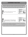
SETTING CLOCK
When the appliance is first plugged in and then turned on, the Digital Display will show
As an example let’s set the clock to 10:35am.
(See page 4 for complete Control Panel Layout.)
1
Timer 2
Timer 1
AM
PM
Set
When the appliance is first plugged in or after a
Temp
Time
power failure, the Digital Display will show Override Economy
Press the Set Times button once. The Clock
Indicator will flash.
Timer 2
Timer 1
Room
3
Timer 2
Timer 1
Press the Set Times button five times to lock in and
complete setting the time. The Clock and Timer
Override Economy
indicators will go out. A small indicator on the
Digital Display will flash to show that the clock is
operating.
– 12 –
Set Times
AM
PM
Room
Temp
Time
Override Economy
Press and hold the “ ” button ; the minutes will
begin to change first, then the time will change by
whole hours. Release the button when AM10:00
shows on the Digital Display. Confirm that you have
selected AM. A small indicator on the left hand side of
the Digital Display indicates the AM setting.
Press and hold the “ ” button again, release the
button when AM10:35 shows. If you go past AM
10:35, then the “ ” button can be used to change the
time settings in reverse.
Clock
Timer 1
on off
Timer 2
ON / OF
Function Lock
Set
2
.
Clock
Timer 1
on off
Timer 2
Set Times
ON / OF
Function Lock
AM
PM
Set
Room
Temp
Time
Clock
Timer 1
on off
Timer 2
Set Times
ON / OF
Function Lock
AM
PM
Set
Room
Temp
Time
Function Lock
Clock
Timer 1
on off
Timer 2
Set Times
ON / OF
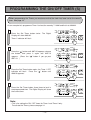
PROGRAMMING THE ON / OFF TIMER (S)
Before programming the Timers you must ensure that the clock has been set to the correct
time. See page 12.
As an example let’s programme Timer 1 to heat the room by 7:10AM and finish at 9:30AM.
1
AM
PM
Press the Set Times button twice. The Digital
Display will show AM6:00.
Timer 1 indicator will flash.
Set
Room
Temp
Time
Clock
Timer 1
on off
Timer 2
Set Times
ON / OF
Function Lock
2
Timer 2
Timer 1
AM
PM
Set
Press the “ ” button until AM7:00 appears, release
the button, then press it again until AM7:10
Override Economy
appears. (Press the “ ” button if you go past
AM7:10.)
Timer 2
3
Timer 1
Room
Temp
Time
Clock
Timer 1
on off
Timer 2
Set Times
ON / OF
Function Lock
AM
PM
Set
Press the Set Times button again, the Timer 1 OFF
indicator will flash. Press the “ ” button
Economy
Overrideuntil
AM9:30 appears.
Room
Temp
Time
Clock
Timer 1
on off
Timer 2
Set Times
ON / OF
Function Lock
4
AM
PM
Press the Set Times button three times to lock in
the programmed time. The Digital Display will show
the current time.
Set
Room
Temp
Time
Function Lock
Note :
・This is for setting the ON / OFF times for Timer 1 and Timer 2 only.
To activate the Timers, please see page 14.
– 13 –
Clock
Timer 1
on off
Timer 2
Set Times
ON / OF
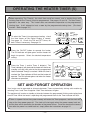
OPERATING THE HEATER TIMER (S)
Before operating The Timer(s), the clock time must be correct, and a starting time and
finishing time for the Timer(s) must be programmed. See pages 12 and 13. The two Timers
operate in the same way. This heater does not commence operation at the programmed
starting time. It will attempt to heat a room by the programmed starting time. (Pre-heat
function. Refer to page 15.)
1
Timer 2
Timer 1
To select the Timer(s) to commence heating, check
the time shown on the Digital Display is correct.
Override Economy
See page 12. Check the ON and OFF times, for
both Timers if necessary. See page 13.
AM
PM
Set
Room
Temp
Time
Clock
Timer 1
on off
Timer 2
Set Times
ON / OF
2
ON / OFF
Press the ON-OFF button to operate the heater.
The ON indicator will glow green and the heater will
begin to operate. Select the desired temperature
setting.
3
Press the Timer 1 and/or Timer 2 button(s). The
Timer indicator(s) will glow and the heater will remain on
standby until one hour prior to the time programmed
into the selected Timer(s) is reached. When this time is
reached, the Timer indicator will flash and the heater will
operate. The ON indicator glows red when the heater
commences operation.
Timer 2
Timer 1
Clock
Timer 1
AM
PM
Set
Room
Temp
Time
Override Economy
Function Lock
SET AND FORGET OPERATION
Your heater can be operated to alternate between Timers automatically during cold weather by
selecting Timer 1 and Timer 2 together. Both Timer indicators will glow.
The appliance will remain on standby at intervals between the programmed finishing and starting times
of each Timer. While the heater is operating with programmed intervals the Timer indicator will flash.
If there is a power failure the system memory will retain the Timer programs, and the clock will
stop at the time power goes off. The clock will start again when the power comes back on,
but the time will be slowed by the duration of the power failure. To set the clock to the correct
time after the power has come back on, simply follow the instructions on page 12.
– 14 –
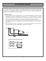
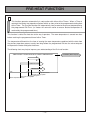
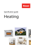
PRE-HEAT FUNCTION
1
This function operates automatically in conjunction with either of the Timers. When a Timer is
selected, the heater may operate anywhere within an hour prior to the programmed starting time
of the Timer. The Pre-heat function will automatically heat a room to the pre-set temperature by
the programmed ON-Time. (ie. Heater will come on earlier to ensure desired temperature is
reached by the programmed time.)
This function is called Pre-heat due to the way it operates. The room temperature is sensed one hour
before reaching the programmed time of either Timer.
The temperature differential at the time of sensing the room temperature combined with the data from
the previous operation governs exactly how long before the programmed ON time the micro-computer
will operate the heater and ignite the burner.
The following chart may help to improve your understanding of the Pre-heat function.
TIME ELAPSED FROM IGNITION TO PRESET TEMPERATURE
Colder than usual
Warmer than usual
7:00
Programmed time
Later than average ignition
Average starting time
Earlier than usual ignition
Room temperature sensed
6:00
6:30
– 15 –
Recorded by Micro Computer
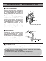
OTHER OPERATING INFORMATION
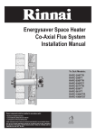
■ HUMIDIFIER TRAY
Your 1004FTR is fitted with an enamelled tray
behind the air outlet so that you can humidify the
air. To fill the tray, open the door as shown in the
diagram and pour water into the tray using the
spout built into the door.
The air will be humidified as it passes over the
water in the tray. DO NOT FILL THE TRAY
WHILST THE UNIT IS IN OPERATION. CLOSE
THE DOOR AFTER FILLING. The 1004FTR is a
very high efficiency appliance. During operation
a small amount of water is produced in the flue
tubes. This drains into the enamel tray. It is
quite normal for a small quantity of water to
remain in the bottom of the tray. If you are using
the humidifier, it will need filling about once a day
during the peak heating season.
■ FAN FILTERS
Humidifier Tray
Max. Fill Line
Access Door
Pull
Filler Spout
Do not force door open too far.
Close door during operation.
Fan Filters
To protect the fan from dust and lint, the
1004FTR is fitted with 2 fan filters. They are
located at the top, rear of the unit. To clean, pull
the filters out of the unit and remove dust with a
soft brush or a vacuum cleaner. Re-fit filters
after cleaning. Your 1004FTR has a filter clean
warning indicator that will illuminate when
required, however, weekly cleaning is
recommended during the peak heating season.
Filter clean
warning
indicator
Filt er
oN
■ OUTSIDE FLUE
On cold days steam may be discharged from the flue outlet. This is normal with a high
efficiency appliance and does not indicate any fault.
The heater and its flue must be installed correctly by an authorised person, and the
installation must conform to all local regulations.
The installation also must comply with the instructions supplied by Rinnai.
This heater must be serviced, installed and removed by an authorised person.
No parts or functions should be modified or permanently removed from the heater or its flue.
– 16 –
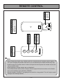
Power source
for operating
remote control.
R2032
C
Increases or decreases
the temperature setting.
TEMPERATURE
ADJUSTMENT
Stops heater manually.
OFF
ON
Operates the heater
manually.
ON BUTTON
OFF BUTTON
OPEN
Simply open the back of the remote
control and replace Lithium battery.
TYPE: CR2032
TO REPLACE BATTERY
BATTERY
REMOTE CONTROL
■ Note
・Some fluorescent lights may interfere with the transmission of remote control signals. In
this case changing the position from which you are operating the remote control may help.
・Avoid leaving the remote control in direct sunlight and do not place the remote close to the
louvres of the heater.
・Avoid getting the remote control wet, or dropping it.
・The remote control works within 5 metres and an angle of 40 to the receiver on the heater.
・Only use the battery type specified. (CR2032).
・Remove battery if control is not going to be used for a long period. This will help to avoid
damage from leaking batteries.
– 17 –
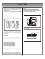
LOCATION
When positioning the unit the main points
governing the location are :
This unit is not designed to be built in.
(1) Flueing
(2) Warm Air Distribution.
This heater must not be installed where
curtains or other combustible materials could
come into contact with it. In some cases
curtains may need restraining.
See diagram for other recommended
clearances.
Flue is not designed to be positioned under
floors, or below the level of the heater.
250mm
50mm
Flue
Terminal
50mm
Flue
Terminal
1000mm
Flue terminal should be positioned away from
flammable materials.
LP GAS
Flue Terminal
Flue fittings must be kept clear of flammable
materials.
– 18 –
LOCATION
Do not flue into natural draught flues or
fireplaces, this unit can only be used with a
Rinnai flue kit.
(A flue kit is available to flue right through to
the rear of most fireplaces Use this kit when
the heater is going to be installed in front of a
fireplace.)
Do not flue unit into other rooms.
Flue terminal must be outside.
flue kits.
Standard installation of flue manifold.
Diagram below shows minimum clearances
and distances from obstructions.
Also check NZS 5261, AG601 and / or local
regulations.
Wall
Non
Flammable
250mm
600mm
Flammable
300mm
500mm
Opposite
Wall
Floor
Side Clearances.
Flue may be positioned directly under
opening windows. with a minimum clearance
of 150 mm.
500mm
Flue sizes :
The A flue is supplied as standard packed
with the appliance. Other sizes options are
AA etc.
AA flue suits walls 75-115mm
A flue suits walls 115-240mm
B flue suits walls 240-400mm
C flue suits walls 400-600mm
D flue suits walls 600-800mm
E flue suits walls 800-1000mm
For information on special extra long flues,
contact Rinnai.
Co-ax internal wall flues are also available.
Separate instructions are supplied with co-ax
– 19 –
Obstruction
LOCATION
Do not install the unit in an unusually dusty
area.
FOR WEATHERBOARD WALLS DRILL
THROUGH CENTRE OF WEATHERBOARD
FROM OUTSIDE, THEN DRILL FROM
INSIDE THROUGH PLASTERBOARD.
(mm)
54
Use flue guard if the terminal is easily
accessible to children.
Check local regulations.
Flue guards are available as an optional
extra.
22
300
50
R2
65
R3
38
465
When drilling the flue hole, check for water
and gas pipes and electric cables before
starting to drill.
GUARD
Use an 80mm (8cm) drill for hole through
wall.
;;;;
;;;;
;;;;
;;;;
;;;;
;;;;
;;;;
;;;;
¢¢¢
;;;
QQQ
;;;
QQQ
¢¢¢
;;;
QQQ
¢¢¢
;;;;
;;;;
;;;;
;;;;
;;;;
;;;;
;;;;
Floor must be level.
Do not use electrical extension cords to
connect unit to power supply.
Keep the power cord away from the flue.
Flue manifold position.
Centre of hole for flue manifold can be drilled
anywhere within the shaded area.
(To avoid studs etc.)
– 20 –
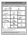
INSTALLATION INSTRUCTIONS
■ The following components are supplied with your 1004FTR.
Flue Manifold .......................1
Spare rubber seal
...........................1
(For weatherboard installations)
Plastic tie for air inlet
connection …………………………1
Flue Adapter
……………………1
Wall Clips
…………………………2
Screws
Back Cover ………………………7
Wall Clip ……………………………2
Flue Manifold ……………………3
Terminal tube ……………………3
Insulation Clip ……………………1
Keys
…………………………………2
Flue Locking Clamp
L
S
……………………1
(
…………1
Flue Lock Stopper
……………1
…………1
Remote Control …………………1
OF
F
ON
Air Inlet Hose
…………2
Back Cover Set …………………1
Remote Control Holder
……1
Insulation Clip ……………………1
Adhesive Tape
…………………2
Instructions
………………………1
(OPTIONAL FLOOR AND WALL BRACKETS ARE AVAILABLE FOR COMMERCIAL INSTALLATIONS)
Check unit supplied is correct for the gas type in your area.
Refer to local gas authority for confirmation of gas type if in doubt.
Refer to data plate located inside front panel.
Check for damage. if the unit is damaged contact your supplier or Rinnai.
Do not install a damaged unit before checking with your supplier.
– 21 –
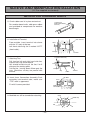
SLEEVE AND MANIFOLD INSTALLATION
(“A” Flue supplied as standard)
METHOD FOR STANDARD WALLS
1. Dis-assemble Manifold from Sleeve.
The Flue consists of 3 parts, sleeve, inside
connectors and tube, outside terminal, (disassemble by pulling hard on outside
terminal and inner connections, then pull
sleeve off outer terminal).
Sleeve
Connection
2. Adjustment of Sleeve Length.
Terminal
Do not extend
beyond red line
Measure wall thickness through previously
drilled 80 mm hole (see P20). End of
sleeve should protrude 5-10 mm from
outside wall. Adjust sleeve length to wall
thickness plus 5-10mm. (Sleeve is
threaded for adjustment.)
Extension joint
under plastic
Extention
("A" and "AA" Flue only)
Adjust length by turning sleeve.
3. Depending on flue set and wall thickness
extension piece “C” may need to be
removed.
A
Cut plastic. remove extension. then follow
instruction 2.
This applies to “A” and “AA” flues only.
There is no extension on other flues. they
can be fully adjusted by turning the
threaded section.
B
"A" and "AA" Flue only
C
Remove extension at this
point it necessary.
4. Fixing Sleeve.
5-10mm
Fix to inside wall. use 3 screws provided.
2°
"TOP"
NOTE :
Flange is marked “TOP” sleeve must be
fitted with this mark UP.
Check sleeve protrudes 5-10mm on
outside.
Fixing Screw
Don't remove green plastic covering from sleeve.
– 22 –
SLEEVE AND MANIFOLD INSTALLATION
(“A” Flue supplied as standard)
METHOD FOR STANDARD WALLS
5. Check rubber seal is in place on terminal.
Terminal seal
(Add "weather board"
seal here)
For weather board walls, add spare rubber
seal provided to compensate for weather
board angle.
6. Installation of Terminal.
"TOP" mark "A"
From outside, insert terminal into sleeve
with the “A” mark at the top.
Left hand side fixing tie is marked “LEFT”
(from inside) .
Label
Fixing tie
Terminal
Cut (leave 20mm free)
7. Attaching Ties.
Pull hard on left and right hand side ties.
clip ties over lugs inside sleeve.
You should be able to pull the ties 2 or 3
slots past the starting point.
Cut the ties. leaving about 20mm past the
lugs. Bend ties so they are parallel with
the wall.
Pull hard
Fixing tie
Terminal
Lug
Sleeve
8. Insert Inner Connection Assembly Push
assembly into terminal tube, make sure
“TOP” mark is uppermost.
Top Mark
Screw
Fix with 3 screws provided.
lnner
Connections
9. Manifold can still be turned after attaching.
Outlet
20˚
Rubber cap
Inlet
– 23 –
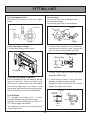
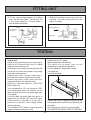
FITTING UNIT
Fix Flue Adapter to Flue.
Manifold with Locking Clamp S as shown
below.
Air Inlet Hose
Connect Air Inlet Hose to Manifold Inlet.
Do not kink the hose.
Secure with plastic tie as-shown below.
Locking clamp S
Flue Manifold
Plastic tie
Flue Adapter
OUT
Inlet elbow
Inlet hose
Fit Air inlet Hose to heater.
Fix Side Back Spacers with screws.
1. Connect the flue outlet to the manifold by
extending the stainless steel sliding tube
until it is fully inserted into the manifold.
Flue Manifold
Sliding Tube
Red Line
Air Inlet Hose
Sliding Tube should not be extended
beyond the RED LINE.
Place top back spacer in position.
Mark the position of the top edge of the top
spacer on the wall. Move the heater away
from the wall. Mark centre lines 20mm down
from the top edge mark, and 12mm in front
the left and right hand sides of the top spacer.
Attach wall brackets at the marked position.
2. Fit the Locking Clamp L over connection
between sliding tube and manifold.
Engage the hook and rotate it until it snaps
against the body of the clamp.
Manifold
Flue outlet
Sliding tube
Fit Inlet Elbow
Fit a suitable inlet fitting to R1 / 2 15mm
threaded fitting on the rear of the heater.
Normally, the most suitable fitting is an RC 1 / 2
15×15mm copper flare elbow.
The appliance can then be connected with
15mm copper tube.
Hook
Locking
clamp
– 24 –
Locking
Clamp
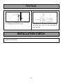
FITTING UNIT
3. Fit the screw clamp between the sliding
tube and the flue elbow. Secure with the
4 mm screw supplied. The flue outlet is
now locked into position.
Screw
Flue Outlet tube
screw clamp
Flue elbow
Locking Clamp L
4. Slide the insulation sleeve up to the flue
manifold. slip the securing clip over the
sleeve as shown.
Fit clip
Locking Clamp S
Slide Insulation sock
Fuel outlet
Sliding tube
Flue elbow
Sock
Flue outlet
Sliding tube
Slide to here
Manifold
TESTING
Testing Unit
Purge air and swarf from gas line. Connect gas.
Refer to A.G.A pipe sizing chart if in doubt
about the size of the gas line.
Connection can easily be reached from the top,
rear of the unit. Check for escapes, using soapy
water after turning gas on.
Remove outer case, 4 screws inside louvre, 2
behind louvre and 3 on the top rear of casing.
Remove test point screw, attach pressure
gauge to test point, (on solenoid valve).
Plug unit in and turn power on, (CAUTION230V inside unit).
Turn thermostat to “HI”, turn control to “ON”.
Unit should ignite within 10 seconds. (If unit
does not ignite first time it will spark again after
10 seconds).
If unit still does not ignite, there may be air in
the gas line, turn control “OFF” then “ON” again.
Check pressure, regulator is factory set, if
pressure is incorrect, check supply before
altering regulator.
Turn control to “OFF” position, remove pressure
gauge and replace test point screw.
Re-light unit, on “HI” setting.
Adjust temperature down Slowly.
The heater will cut down, then cut out
(Depending on the room temperature).
Turn the power off. Replace the casing.
Turn power on.
Re-check operation.
Replace top spacer, clipping the spacer into the
wall brackets at the same time as attaching it to
the heater.
Secure top spacer with the screws provided.
THE HEATER IS NOW SECURED TO THE WALL.
– 25 –
TESTING
Spacer
Leveling screws (Adjustable legs)
;;;
;;;
;;;
;;;
;;;
;;;
;;;
;;;
;;;
;;;
;;;
;;;
;;;
;;;
;;;
;;;
;;;
;;;
;;;
;;;
;;;
;;;
;;;
Up to 10mm
Adjustable Leg
OPTIONAL FLOOR BRACKETS ARE AVAILABLE
FOR COMMERCIAL INSTRUCTIONS.
If necessary the unit can be levelled using the
adjustable legs under the front right and left
hand side legs.
INSTALLATION CHECK
Please contact Rinnai
– 26 –
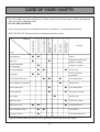
CARE OF YOUR 1004FTR
This unit needs very little maintenance. Simply clean the fan filters once a week and wipe the
outer case with a soft damp cloth.
DO NOT USE SOLVENTS.
Check the flue terminal occasionally to make sure shrubs etc. have not grown around it.
Power Cut
●
●
Gas Filter Blocked
●
●
Re-ignite manually after
power is restored
Purge air (Installer)
●
●
Service Call
Check customers
instructions
●
●
Flue terminal obstructed
Remedy
Plug In
●
(Initial installation)
Air in gas pipe
Mis-ignition
Takes too long to
warm the room
●
Noisy ignition
●
Smell of gas
Burner doesn’t ignite
Not Plugged In
Combustion stops during
operation
Cause
No operation lamp
Problem
Unusual combustion
UNIT CHECK LIST Please check this list before asking for service.
●
Flue manifold not connected
●
Clear obstruction
●
Service Call
Louvre obstructed
●
●
Clear obstruction
Air filter blocked
●
●
Clean filter (weekly)
●
Gas escape
Room too large
“ON” Timer is set
●
●
Gas turned off at meter
●
Function Lock Set
●
●
Service Call
●
Check with retailer
●
Cancel“ON”Timer
Turn gas on
Cancel Function Lock
If you are unsure about the way the unit is operating, contact Rinnai or your agent.
– 27 –
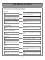
PRE-SERVICE CHECK
Before asking for a service call please check the following.
These points are part of the normal operation of the unit.
At ignition :
Warm air does not start when the burner
lights.
The fan is started automatically after a short delay.
This is to allow the heat exchanger to warm up,
helping to avoid cold draughts.
Smoke or strange smells are produced on
the first trial light up after installation.
This is caused by grease or oil on the heat
exchanger and dust, and will stop after a short time.
Sharp clicking noises at ignition, or when
the unit cuts down on the thermostat, or
goes out.
This is simply expansion noise from the heat
exchanger.
During combustion :
Clunking noise when the thermostat
operates.
This is the sound of the solenoid gas valves opening
and closing.
When the unit is turned off :
This is to remove the residual heat from the heat
exchanger. The fan will stop when the unit cools
down.
Convection fan continues to run after
turning off.
Other points :
Steam is discharged from the flue
terminal.
High efficiency appliances tend to discharge water
vapour on cold days. This is normal.
Heater does not start even when ON
button is pushed and thermostat is on
HIGH.
Check timer. Timer must be in the “OFF” position
for manual operation.
Timers :
Timers do not operate at set time.
Timers may either be unactivated or incorrectly
programmed. Repeat programming. Refer to
pages 14 and 15.
Timer operates for 30 seconds then cuts
out.
Room temperature may be higher than set
temperature. Adjust temperature upwards if
desired.
– 28 –
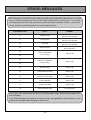
ERROR MESSAGES
The Energysaver 1004FTR has the ability to check its own operation continuously. If a fault
occurs, an Error Message will flash on the Digital Display of the control panel. This assists
with diagnosing the fault, and may enable you to overcome a problem without a service call.
Please quote the code displayed when inquiring about service.
CODE DISPLAYED
FAULT
REMEDY
11
Ignition failure
Check gas is turned ON.
Service call if repeated.
12
Flame failure
Check gas is turned ON.
Service call if repeated.
14
Overheat
Clean filter
Service call if repeated.
16
Room overheat
Lower room temperature
to less than 40℃.
Room Temperature
Sensor faulty
Service call.
Overheat Temperature
Sensor faulty
Service call.
53
Sparker failure
Service call.
61
Combustion fan failure
Service call.
70
Faulty ON / OFF switch
Service call.
71
Faulty solenoids
Service call.
72
Faulty Flame Rod
Service call.
73
Communication Error
Turn heater OFF,
then ON again.
31
32
33
34
In all cases, you may be able to clear the Error Message simply by turning the heater OFF,
then ON again.
If the Error Message still remains or returns on the next operation contact Rinnai or your
nearest service agent and arrange for a service call.
– 29 –
SAFETY DEVICES
Overheat Switch :
This device automatically cuts the gas off if the heater exceeds a predetermined temperature.
This is normally caused by an obstruction in front of the louvres, or a blocked fan filter.
If this switch operates, turn the unit off, remove the obstruction (clean filters) and let the unit cool
off before re-operating.
Two Fusible Links
Backs up the overheat switch. If a fusible link cuts the unit off, a service call by an authorised
person is required to replace the link.
Flame Failure Device
If the flame goes out during operation this device cuts the unit off (lockout) . To reset, turn the unit
off, then on again.
Fan Switch
Turns the fan on automatically when the heat exchanger warms up and off when it cools down.
This helps to prevent cold draughts and maximises efficiency.
SERVICE
Rinnai New Zealand has a New Zealand wide service network please call 0800 RINNAI to get in
contact with your nearest Service Center. Rinnai recommend that this appliance is serviced every
2 years.
– 30 –
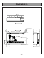
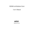
DIMENSIONS
Air Filter
357.5
Remote Control Sensor
930
Filter Indicator
315
Operation Indicator
300
GAS CONNECTION
Clip
200
115
500
R338
670
Cavity Opening
165
250
397
R265
330
160
– 31 –
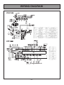
WIRING DIAGRAM
– 32 –
NOTES
– 33 –
GUARANTEE
DEAR CUSTOMER
THANK YOU FOR PURCHASING THIS RINNAI APPLIANCE. WE ARE PLEASED TO ADVISE THAT
RINNAI PRODUCTS ARE NOW COVERED BY A 2 YEAR. GUARANTEE: FREE PARTS AND
LABOUR FOR THE FIRST YEAR AND PARTS ONLY FOR THE SECOND YEAR.
- THIS GUARANTEE IS IN ADDITION TO ANY GUARANTEES WHICH
CONSUMERS MAY HAVE UNDER THE CONSUMER GUARANTEES ACTSHOULD YOU HAVE ANY QUERIES REGARDING THIS GUARANTEE PLEASE CONTACT YOUR
LOCAL RINNAI AGENT.
Please record below the following information for your own records.
Your Retailer:
Address:
Phone:
Date of Purchase:
Your Installer:
Installer’s Licence No.
Address:
Phone:
Date of Installation:
– 34 –
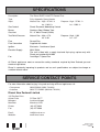
SPECIFICATIONS
Description
The Rinnai RHFE-1004FTR Forced Flue
Type
Fully Automatic Space Heater
Input
Natural Gas : High : 37 MJ / h
Natural Gas : Lo : 11MJ / h
Gas Control
Rinnai Electronic Modulating Control
Burner
Stainless Steel, Ribbon Type
Gas Inlet
R1 / 2” Male Thread (15mm)
Test Point Pressure
Natural Gas : High : 0.76
Natural Gas : Lo : 0.49
Flue
Forced Flue
Flue Connection
Supplied with heater
Ignition
Electronic - Continuous Spark
Electrical Supply
230V, 50Hz
The unit is fitted with a supply lead and 3 pin plug, replace only with
Rinnai part number 90161894
Fan
Centrifugal 7 Speed Fan
Propane : High : 37 MJ / h
Propane : Lo : 11MJ / h
Propane : High : 2.33
Propane : Lo : 1.07
All Rinnai appliances meet or exceed the safety standards required by New Zealand gas and
electrical regulations.
Rinnai is constantly improving its products and as such specifications are subject to change or
variation without notice.
SERVICE CONTACT POINTS
For more information about buying, living and servicing of Rinnai appliances call:
・Consumers
・Installers
0800 RINNAI (0800 746 624)
0800 TO RINNAI (0800 86 746 624)
Rinnai New Zealand Limited
105 Pavilion Drive
Ariport Oaks
Mangere
Manukau
PO Box 53177
Auckland Airport
Manukau 2150
Phone:
Fax:
(09) 257 3800
(09) 257 3899
Email:
Website:
[email protected]
www.rinnai.co.nz
Printed in Japan
1004F-2151×03(00)
2009.04 K