1
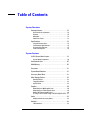
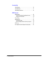
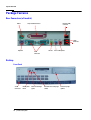
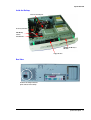
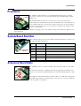
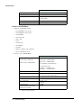
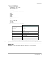
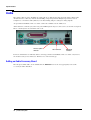
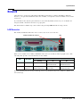
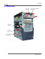
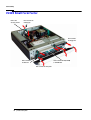
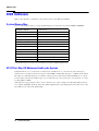
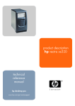
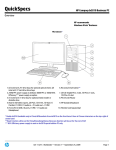
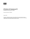
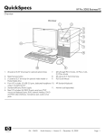
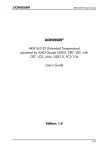
product description hp vectra vl420 technical reference manual hp business pcs www.hp.com/go/vectrasupport Notice The information contained in this document is subject to change without notice. Hewlett-Packard makes no warranty of any kind with regard to this material, including, but not limited to, the implied warranties of merchantability and fitness for a particular purpose. Hewlett-Packard shall not be liable for errors contained herein or for incidental or consequential damages in connection with the furnishing, performance, or use of this material. This document contains proprietary information that is protected by copyright. All rights are reserved. No part of this document may be photocopied, reproduced, or translated to another language without the prior written consent of Hewlett-Packard Company. Acrobat ™ is a trademark of Adobe Systems Incorporated. NVIDIA™, GeForce2 MX™, TNT™ and Vanta™ are trademarks of NVIDIA Corporation. ATI™ is a trademark of ATI Technologies Inc. Microsoft®, Windows®, Windows NT® and Windows XP® are U.S. registered trademarks of Microsoft Corporation. Intel®and Pentium® are registered trademarks of Intel Corporation. Analog Devices® is a registered trademark of Analog Devices Incorporated. Sound Blaster® is a registered trademark of Creative Technology Ltd. HP France Business Desktop Division 38053 Grenoble Cedex 9 France © 2001 Hewlett-Packard Company Information Roadmap Use the icon in Acrobat Reader to search for information in this PDF. The following types of information are available for HP Business PCs: Technical Reference See the HP Technical Reference Manual. This Technical Reference Manual is a technical reference and BIOS document for personnel providing system level support. It is available in PDF format on the HP support web site (www.hp.com/go/vectrasupport or www.hp.com/go/e-pcsupport). It is presented in modular form to provide quick and easy access to technical information on the HP Business PC. It is made up of the following components: • The Introduction & HP Business PC Overview provides a quick reference guide to the hardware components and BIOS used in the latest HP Business PCs. It also lists some of the available accessories. • Product Description (this document). Provides technical information specific to a HP Business PC. This includes summary information on product hardware and detailed information on the BIOS. Read this manual to see which hardware components are in the PC. • HP Business PC Technology. Provides an in-depth guide to the hardware in all of the featured HP Business PCs. Subjects covered include chipsets, processors, graphics controllers, hard disk drives and optical drives. Installing, Configuring and Upgrading See the HP Service Handbook Chapter or the HP Upgrade Guide. The Service Handbook Chapter, available in PDF format on the HP support web site (www.hp.com/go/vectrasupport or www.hp.com/go/e-pcsupport), provides information on: • HP Business PC configurations • Replacement parts • Available accessories. The Upgrade Guide will help you upgrade and replace components in your HP Business PC, including the hard drive, memory, battery, power supply, and optical drives. More information is available on the HP support web site (www.hp.com/go/vectrasupport). Troubleshooting See the HP Troubleshooting Guide. The Troubleshooting Guide, available in PDF format on the HP support web site (www.hp.com/go/vectrasupport or www.hp.com/go/e-pcsupport) will help you: • Troubleshoot your HP Business PC • Find out where to get more information. product description 3 Discover and use your product See the HP Quick Start card and HP Quick User’s Guide. The Quick Start card provided with your HP Business PC will help you: • Set up and begin using your HP Business PC for the first time • Upgrade and replace components in your HP Business PC, including the hard drive, processor memory, add-on cards and optical drives. More information is available on the HP support web site (www.hp.com/go/vectrasupport or www.hp.com/go/e-pcsupport). • Find out where to get more information. The Quick User’s Guide provided with your HP Business PC includes basic troubleshooting information, technical specifications, warranty and legal information. Your computer’s online information Your computer may contain online help information on the hard disk. It includes information on: • Troubleshooting and how to use HP Instant Support • Linking to useful HP web sites. Information on the hp support web site Refer to the HP support web site (www.hp.com/go/vectrasupport or www.hp.com/go/e-pcsupport) for a wide range of information, including: • Downloadable documentation • Service and support options • The latest BIOS, drivers and utilities • Answers to Frequently Asked Questions. System recovery cd-roms Used for a full system recovery or alternative OS installation. Includes instructions on how to recover your preloaded software including operating system, drivers and utilities. 4 product description Finding Information Use the following table to determine where to locate particular types of information: Type of Information • Support phone numbers Location Quick User’s Guide Technical support contact information • Warranty information • • How to set up your computer Quick Start Card (details) Quick User’s Guide (general information) • Operation of your computer Operating system and application manuals • Diagrams and detailed instructions on installing add-on devices • Internal wire connections for adding hard drives, CD-ROM, etc. • Memory expansion and replacing devices Upgrade Guide LAN configuration • LAN controller LAN Card Ready Program (available on the HP support web site) • • Identifying the problem Technical Reference Manual Troubleshooting Guide Information on errors • Problem solving • Troubleshooting • Parts list • Accessories list • • BIOS Service Handbook Chapter Technical Reference Manual Connectors • IRQ • POST setup • Specifications • System board layout • Technical diagrams • product description 5 Bibliography Datasheets and other information can be obtained at: ❒ Intel Chipsets developer.intel.com ❒ Intel Dynamic Video Memory Technology www.developer.intel.com/business/products/chipsets/dvmt_white.pdf ❒ Pentium 4 Processors www.intel.com/pentium4 ❒ Analog Devices AD1885 www.analogdevices.com ❒ Intel LAN card www.intel.com/support/network ❒ ATI Rage 128 Pro graphic card www.ati.com ❒ NVIDIA graphic cards www.nvidia.com ❒ Hewlett-Packard white papers are available on a variety of subjects including AGP graphics and SDRAM memory at: www.hp.com/go/library 6 product description Table of Contents System Overview Package Features . . . . . . . . . . . . . . . . . . . . . . . . . . . . . . 10 Rear Connectors (all models) . . . . . . . . . . . . . . . . . . . . . . . 10 Desktop . . . . . . . . . . . . . . . . . . . . . . . . . . . . . . . . . . . . . . . 10 Minitower . . . . . . . . . . . . . . . . . . . . . . . . . . . . . . . . . . . . . 12 Small Form Factor . . . . . . . . . . . . . . . . . . . . . . . . . . . . . . . 13 Specifications . . . . . . . . . . . . . . . . . . . . . . . . . . . . . . . . . 15 Physical Characteristics. . . . . . . . . . . . . . . . . . . . . . . . . . . Environmental Specifications . . . . . . . . . . . . . . . . . . . . . . . Acoustic Noise Emission. . . . . . . . . . . . . . . . . . . . . . . . . . . Power Consumption . . . . . . . . . . . . . . . . . . . . . . . . . . . . . . 15 15 15 16 System Features VL420 System Board Layout. . . . . . . . . . . . . . . . . . . . . . 18 System Board Components . . . . . . . . . . . . . . . . . . . . . . . . 19 Architectural View . . . . . . . . . . . . . . . . . . . . . . . . . . . . . 20 Main Memory . . . . . . . . . . . . . . . . . . . . . . . . . . . . . . . . . 20 Processors . . . . . . . . . . . . . . . . . . . . . . . . . . . . . . . . . . . 21 System Board Switches . . . . . . . . . . . . . . . . . . . . . . . . . 21 Accessory Board Slots . . . . . . . . . . . . . . . . . . . . . . . . . . 21 Mass Storage Devices. . . . . . . . . . . . . . . . . . . . . . . . . . . 23 Hard Disk Drives . . . . . . . . . . . . . . . . . . . . . . . . . . . . . . . . 23 Floppy Disk Drives . . . . . . . . . . . . . . . . . . . . . . . . . . . . . . . 23 Optical Drives . . . . . . . . . . . . . . . . . . . . . . . . . . . . . . . . . . 23 Graphics . . . . . . . . . . . . . . . . . . . . . . . . . . . . . . . . . . . . . 29 Nvidia GeForce2 MX Graphics Card . . . . . . . . . . . . . . . . . . Nvidia GeForce3 Ti200 Graphics Card . . . . . . . . . . . . . . . . Nvidia TNT2 Vanta Graphics Card . . . . . . . . . . . . . . . . . . . ATI Rage 128 Pro and ATI Rage 128 Ultra Graphics Card . 29 30 30 31 Audio . . . . . . . . . . . . . . . . . . . . . . . . . . . . . . . . . . . . . . . 32 Adding an Audio Accessory Board . . . . . . . . . . . . . . . . . . . 32 Network . . . . . . . . . . . . . . . . . . . . . . . . . . . . . . . . . . . . . 33 LAN Connector. . . . . . . . . . . . . . . . . . . . . . . . . . . . . . . . . . 33 product description 7 Serviceability VL420 Desktop. . . . . . . . . . . . . . . . . . . . . . . . . . . . . . . . 36 VL420 Minitower . . . . . . . . . . . . . . . . . . . . . . . . . . . . . . 37 VL420 Small Form Factor . . . . . . . . . . . . . . . . . . . . . . . . 38 BIOS Overview BIOS Summary . . . . . . . . . . . . . . . . . . . . . . . . . . . . . . . . 40 Entering the Configuration and Diagnostics menu . . . . . . . . 40 Using the HP Setup Program . . . . . . . . . . . . . . . . . . . . . . . 40 Power Saving . . . . . . . . . . . . . . . . . . . . . . . . . . . . . . . . . 41 BIOS Addresses . . . . . . . . . . . . . . . . . . . . . . . . . . . . . . . 42 System Memory Map . . . . . . . . . . . . . . . . . . . . . . . . . . . . . 42 HP I/O Port Map (I/O Addresses Used by the System) . . . . . 42 POST Tests . . . . . . . . . . . . . . . . . . . . . . . . . . . . . . . . . . 45 HP e-DiagTools Preboot Diagnostics (Beep Codes) . . . . . 50 8 product description 1 System Overview This chapter introduces the internal and external features, and lists the specifications of the HP Vectra VL420 PC. System Overview Package Features Rear Connectors (all models) Mouse Network (LAN) connector 25-pin Parallel Connector 2 USB Connectors Keyboard Line Out Line In Microphone Serial Connectors Desktop Front Panel 2 USB Connectors On/Off power button 10 product description Power on status light (green) Hard disk drive activity light (amber) Disk activity light (yellow) System Overview Inside the Desktop Processor covered by fan Accessory board slots Main Memory Sockets Hard disk drive CD-ROM, CD-RW drive, or DVD drive Floppy disk drive Rear View Location of the voltage switch and power connector on the desktop product description 11 System Overview Minitower Front View Disk activity light (yellow) On/Off power button Power on status light (green) USB connectors Hard disk drive activity light (amber) Inside the Minitower Floppy disk drive CD-ROM, CD-RW drive, or DVD drive Processor Main Memory Accessory board slots 12 product description Hard disk drive System Overview Rear View Location of the voltage switch and power connector on the minitower Small Form Factor Front Panel On/Off power button 2 USB Connectors Power on status light (green) Hard disk drive activity light (amber) Disk activity light (yellow) product description 13 System Overview Inside the Small Form Factor Processor covered by fan Power supply unit Main Memory Sockets Accessory board slots Hard disk drive CD-ROM, CD-RW drive, or DVD drive Floppy disk drive Rear View Location of the voltage switch and power connector on the small form factor 14 product description System Overview Specifications Physical Characteristics Characteristic VL420 Desktop PC VL420 Minitower PC VL420 SFF PC Weight (configuration with 1 CD-ROM drive, excluding keyboard and display) 10kg (22 pounds) 13.4kg (29.5 pounds) 9.2kg (20.3 pounds) Dimensions Width: 43.5cm (17.13in.) Width: 20.5cm (8.1in.) Width: 34.0cm (13.38in.) Height: 13.5cm (5.31in.) Height: 47.6cm (18.7in.) Height: 9.5cm (3.74in.) Depth: 43cm (16.92in.) Depth: 44.7cm (17.6in.) Depth: 40.5cm (15.95in.) 0.19m2 (2.05 sq ft) Footprint 0.09m2 (0.97 sq ft) 0.14m2 (1.51 sq ft) Environmental Specifications Environmental Specifications (System Processing Unit, with Hard Disk) NOTE Operating Temperature +5°C to +35°C (+41°F to 95°F) Storage Temperature -40°F to +70°F (-40°C to +158°C) Operating Humidity 15% to 80% (relative) Storage Humidity (operating) 15% to 80% (relative), non-condensing at 40°C (104°F) Storage Humidity (non operating) 8% to 85% (relative), non-condensing at 40°C (104°F) Operating temperature and humidity ranges may vary depending on the mass storage devices installed. High humidity levels can cause improper operation of disk drives. Low humidity ranges can aggravate static electricity problems and cause excessive wear of the disk surface. Acoustic Noise Emission Characteristic Acoustic noise emission (IS O7779) • Idle (typical) Operating with hard disk access • Operating with floppy disk access • Operating with CD access • VL420 Desktop PC VL420 Minitower PC VL420 SFF PC Sound pressure level at operator position Sound pressure level at operator position Sound pressure level at operator position LpA ≤ 28 dB(A) LpA ≤ 22 dB(A) LpA ≤ 29 dB(A) LpA ≤ 28 dB(A) LpA ≤ 22 dB(A) LpA ≤ 29 dB(A) LpA ≤ 41 dB(A) LpA ≤ 34 dB(A) LpA ≤ 38 dB(A) LpA ≤ 36 dB(A) LpA ≤ 40 dB(A) Sound power level Sound power level Sound power level LwA ≤ 3.5 B(A) LpA ≤ 3.6 B(A) LpA ≤ 3.6 B(A) LwA ≤ 3.6 B(A) LpA ≤ 3.7 B(A) LpA ≤ 3.8 B(A) LwA ≤ 4.7 B(A) LpA ≤ 4.7 B(A) LpA ≤ 4.4 B(A) LwA ≤ 4.7 B(A) LpA ≤ 4.7 B(A) LpA ≤ 4.5 B(A) LpA ≤ 39 dB(A) 1 Idle (typical) • Operating with hard disk access • • • Operating with floppy disk access Operating with CD access 1.LwAd = LwA + 3 dB(A). product description 15 System Overview Power Consumption As an ENERGY STAR partner, HP has determined that this product meets the ENERGY STAR guidelines for energy efficiency (Windows 2000 and Windows 98 only). This value is only achieved when “Suspend to RAM” (S3 mode) is enabled. To enable Suspend to RAM, enter the PC’s Setup program by pressing F2 during startup and select the Power menu. In normal mode power consumption will be around 45W. Characteristic VL420 Desktop PC VL420 Minitower PC VL420 SFF PC 100-127V 5A 100-127V 5A 100-127V 4A 200-240V 3A 200-240V 3.5A 200-240V 2A 50/60Hz 50/60Hz 50/60Hz Power Supply Input voltage • Voltage selection switch • Input frequency • Power consumption • 115V/60Hz and 230V/50Hz 110W Maximum Operating Typical • Sleep (S3) • Off • Available minimum continuos output power NOTE 45W 3.5W 3.2W 185W 250W 165W The power consumption figures given in the table above are valid for the standard configuration as shipped. For more information, refer to the product’s data sheet at HP’s web site: www.hp.com/go/desktops When the computer is turned off with the power button on the front panel, the power consumption falls below 4W, but it is not zero. The special on/off method used by these computers considerably extends the lifetime of the power supply. To reach zero power consumption in “off” mode, either unplug the power outlet or use a power block with a switch. 16 product description 2 System Features This chapter describes core components of HP Vectra VL420 PCs such as processors, chipsets, mass storage devices, graphics controllers, audio controllers, network features and input devices. System Features VL420 System Board Layout The HP Vectra VL420 PC system board features a Socket 478B for a Pentium 4 processor, three DIMM main memory slots, three PCI slots and one AGP slot. 18 product description System Features System Board Components The following diagram shows where the different slots and connectors are located on the system board: Keyboard Mouse Chassis intrusion switch connector Parallel 2 x Serial AGP Slot (for AGP card) System fan connector (minitower and SFF only) Processor socket (see page 21) Microphone-in Line-in Line-out CPU fan connector Power supply fan connector (desktop only) LAN 2 x USB CD audio connector Power connector Internal speaker connector Heat sink covering Intel 845 chipset PCI Slot 1 DI MM DI MM 1 DI MM 2 3 PCI Slot 2 PCI Slot 3 Power supply connector Floppy connector Battery IDE connectors SCSI card LED connector USB connector Switch block (see page21) Status panel connectors WARNING There is a risk of explosion if the battery is not replaced by the correct type. Make sure you dispose of used batteries according to instructions provided. product description 19 System Features Architectural View The following diagram shows the VL420 Intel 845 Chip architecture: Pentium 4 processor System Bus 3.2GB/s Memory Bus AGP graphics card Intel 845 AGP Slot AGP 4X 1066MB/s Main Memory 133MHz SDRAM 2 UATA 100 Disks Hard Disk Hard Disk 4 USB Slots 2 rear + 2 front ICH2 chip 2 IDE Drives 3 PCI Slots CD-ROM DVD/CD-RW/Zip PCI Bus Audio AD1885 Super I/O Flash BIOS Serial/Parallel/FDD/PS2 Integrated Intel® Pro/100 VE Network Adapter (10 Base-T/100 Base-TX LAN Interface) Main Memory DIMM slots There are three 168-pin DIMM slots on the system board for installing main memory. You can install 133MHz SDRAM modules, these are available in 64, 128, 256 and 512MB memory modules. 32MB memory modules are not supported. You can install a maximum of 1.5GB (3 x 512MB modules). You can only use non-ECC memory modules. 20 product description System Features Processors 478B PGA The VL420 is equipped with a socket 478B Intel Pentium 4 processor. The Socket processor is connected to the system board through a Pin Grid Array (PGA) 478B Socket. A heatsink and fan (not shown) cover the processor to prevent it from overheating. If the heatsink is removed, the thermal interface material between the heatsink and the processor must be replaced by a new one. If no thermal interface is used or the old one is re-used, then cooling may be impaired and the processor damaged. To find out more about Pentium 4 technology, refer to the Technical Reference Manual - HP Business PC Technology. System Board Switches The following table gives the functionality and default position of switches on the system board switch block: System Board switches Switch Default Position Function 1-4 OFF Reserved 5 OFF ON = Clear CMOS 6 OFF ON = Clear Password 7 OFF ON = BIOS crisis mode recovery 8 OFF Not used 9 ON OFF = Boot block FLASH protect 10 OFF Not used Accessory Board Slots AGP The VL420 has four accessory board slots: three PCI slots and one 1.5V AGP slot. The PCI slots are PCI 2.2 compliant and each slot supports a maximum total current of 375 mA. The VL420 small form factor PCI slot blank panels are half size. PCI 1 PCI 2 PCI 3 Your graphics card is installed in the AGP slot. The 1.5V AGP slot is backward compatible with AGP 1x, 2x and 4x modes. A latch on one end of the AGP slot locks the graphics card in place. product description 21 System Features PCI Slot Numbers Your PC uses logical slot numbers in the BIOS Setup program. You need to know these logical slot numbers if you want to change the PCI slot configuration in the Setup program. VL420 PCI Mapping Table Slot# Bus Device PCI Device 0 0 MCH: Host bridge 0 2 MCH: AGP bridge 0 30 ICH: Hub interface to PCI bridge 0 31 ICH: PCI to LPC bridge 0 31 ICH: IDE controller 0 31 ICH: USB controller 0 31 ICH: SMBUS controller 0 31 ICH: AC97 audio controller 2 9 PCI slot 1 1 2 10 PCI slot 2 2 2 11 PCI slot 3 3 1 0 AGP device AGP slot 1 8 LAN controller Embedded 22 product description System Features Mass Storage Devices Hard Disk Drives A 3.5-inch hard disk drive is supplied on an internal shelf in some models. These hard drives can be provided with the PC. To see which other hard disk drives can be purchased as accessories for the VL420, refer to www.hp.com/desktops/products/accessories. 20GB UltraATA 100 40GB UltraATA 100 20GB Ultra-ATA 100 40GB Ultra-ATA 100 80GB Ultra-ATA 100 18GB U160SCSI1 36GB U160SCSI1 Average Seek Time (ms) 8.9 to 12.1 8.5 to 8.9 9.5 4.5 Track-to-Track Seek TIme (ms) 1.5 1.2 0.95 0.3 Full Stroke Seek Time (ms) 20 to 25 15 - 11 Rotational Speed (RPM) 5400 7200 7200 10000 Buffer Size (MB) 2 2 2 8 1.SCSI is not available for small form factor models. To find out about Ultra-ATA 100 and U160-SCSI hard disk drive technology, refer to the Technical Reference Manual - HP Business PC Technology. Floppy Disk Drives All models are supplied with a 3.5-inch floppy disk drive. Optical Drives Desktop and mintower models are fitted with a 48✕ Max-speed IDE CD-ROM drive. The small form factor model is fitted with a slim 24X Max-speed IDE CD-ROM drive. These drives can play standard CDROM discs, conforming to optical and mechanical standards as specified in the Red and Yellow Book. These drives can also be purchased as accessories. Refer to www.hp.com/desktops/products/accessories. To find out about CD-ROM and DVD drive technology, refer to the Technical Reference Manual - HP Business PC Technology. Minitower and Desktop Drives Features of the CD-ROM Drive • Supported CD-ROM formats: • • CD-ROM Mode 1 and 2 data disc Photo-CD Multisession CD Audio disc • Mixed mode CD-ROM disc (data and audio) • CD-ROM XA • • • CD-I, CD-Extra, CD-R, CD-RW. Interface: E-IDE/ATAPI. product description 23 System Features Description Loading Type Motorized tray Data Transfer Rate Outer side 7,200 KB/s (48x) Access Time Average stroke (1 / 3) 110ms Full Stroke 180ms Buffer Memory Size 128KB Rotational Speed Approx. 11,100 rpm maximum Features of the CD-RW Drive • • Supported CD-ROM formats: • CD-ROM Mode-1 data disc • CD-ROM Mode-2 data disc • CD-ROM XA • CD Audio disc • Video CD • CD-I • CD-I Ready • CD-I Bridge • CD-WO • Enhanced Music CD (CD Plus) • Photo CD Multi-session. Interface type: E-IDE/ATAPI. Description Data Transfer Rate (1 KB=210 byte=1,024 bytes) (1 MB=220 byte=1,048,576 bytes) Sustained Data Transfer Rate1 Reading - 40X = 6,000 KB/s (Max) Writing - 16X = 2,400 KB/s (Max) (CD-R: 2400 KB/s, CD-RW: 1500 KB/s) Burst Data Transfer Rate PIO Mode 4: 16.7 MB/sec (max.) DMA Mode 2: 16.7 MB/sec (max.) Buffer Size 2 MB Access Time Average Random Access Time: 95 ms (typical) Full Stroke Access Time: 180 ms (typical) Rotational Speed Variable (approx. 5,400 rpm max.) Interface IDE/ATA-2 MMC Compliant Power Requirements +5V and +12V 12.4W max. Recording Formats (120mm and 80mm discs for CD-R, 120mm only for CD-RW) ISO 9660 UDF 1.5 1. Depends on drive specification. 24 product description System Features Features of the DVD-ROM Drive • • • Supported CD-ROM formats: • CD-ROM Mode 1 and 2 data disc • Photo-CD Multisession • CD Audio disc • Mixed mode CD-ROM disc (data and audio) • CD-ROM XA • CD-I • CD-Extra • CD-R • CD-RW Supported DVD-ROM formats:. • DVD-ROM • DVD-R (4.7GB/3.9GB) • DVD-RW • DVD + RW. Interface: E-IDE/ATAPI, Support Ultra DMA 66. Description Data Capacity: Capacity DVD-ROM Up to 8.5 GB/side Capacity DVD-RAM 4.7 GB/side Capacity DVD-R 4.7 GB/side Capacity CD 650 MB Data Transfer Rate 16X (maximum) DVD 40X (maximum) CD-ROM Loading Type Motorized tray Access Time 120 ms (DVD) 90 ms (CD-ROM) NOTE Buffer Memory Size 512 KB Acoustic Noise 52 dB Rotational Speed Approx. Variable (Approx 7,300 rpm max.) If a disk is still in the drive after power failure or drive failure, the disk can be reclaimed by inserting a straightened paperclip into the small hole at the bottom of the door. DVD Region Codes The DVD drive is able to play DVD video discs from all regions (see the following table). product description 25 System Features After setting the DVD region (by playing a DVD video for the first time), the DVD region can be changed a further four times; after that the DVD drive will only play DVD videos from the last DVD region that was set. Regional Codes Region 1 USA & Canada 2 Europe (excluding former USSR countries ), Japan, Near East (including Iran and Egypt), South Africa 3 South East Asia, South Korea 4 Latin America & Oceania (Australia, New Zealand) 5 Africa (excluding Egypt and South Africa), Eastern European countries, Sub-Indian continent 6 China Small Form Factor Optical Drives Features of the Slim CD-ROM drive • CD-DA • CD-ROM Mode1, Mode 2 • CD-I (Mode 2 Form 1 and 2) • Photo-CD (single and multisession) • Enhanced CD. Description Host Interface IDE (ATAPI) Disc Diameter 120 mm Storage Capacity 656 Mbytes Data Transfer Rate Burst: 33.3 MBs (max) Average Access Time 115msec (average) Buffer Memory 128 Kbytes Rotational speed 5136rpm Features of the Slim CD-RW Drive • • Supported CD-ROM formats (read and write): • CD-ROM • CD-Text • Video CD • CD-Extra • CD-DA • CD-ROM XA • CD-R (Orange Book Part 2) • CD-RW (Orange Book Part 3). Supported CD-ROM formats (read only): • • Photo CD (single and multi session). Interface type: E-IDE/ATAPI. 26 product description Sustained: 1545 ~3600KBs System Features Description Write/Read Speed Write CD-R 8X max. Write CD-R/W 8X max. Read 24X max. Sustained Data Transfer Rate (maximum) 3,600 KB/s CAV Data Capacity 700 MB or up to 74 minutes of audio per disc Random Access Time (Average) 140 ms Buffer Memory Size 2 MB Loading Type Manual Mounting Type Horizontal and vertical Weight 200 g approx. Acoustic Noise < 45 dBA at 1m Reliability MTBF 6,000 POH Features of the Slim DVD-ROM Drive • Supported formats (read only): • DVD-ROM • CD-ROM Mode 1 and 2 data disc • Photo-CD Multisession • CD Audio disc • Mixed mode CD-ROM disc (data and audio) • CD-ROM XA • CD-I • CD-Extra • CD-Text • CD-R • CD-RW. product description 27 System Features • Interface: E-IDE/ATAPI, Ultra DMA mode 2 (33.3 MB/s). Description Data Capacity: Capacity DVD-ROM Up to 8.5 GB/side Capacity DVD-RAM 4.7 GB/side Capacity DVD-R 4.7 GB/side Capacity CD 700 MB Data Transfer Rate 8X max. DVD 24X max. CD-ROM Access Time (Average) 90 ms for single-layer DVD-ROM 130 ms for dual-layer DVD-ROM 85 ms for CD-ROM NOTE Loading Type Manual, with electrical release of tray Mounting Type Horizontal and vertical Weight 180 g typical Buffer Memory Size 512 KB Acoustic Noise < 46 dBA at 0.5m Reliability MTBF 80,000 POH If a disk is still in the drive after power failure or drive failure, the disk can be reclaimed by inserting a straightened paperclip into the small hole at the bottom of the door. DVD Region Codes The DVD drive is able to play DVD video discs from all regions (see table below). After setting the DVD region (by playing a DVD video for the first time), the DVD region can be changed a further four times; after that the DVD drive will only play DVD videos from the last DVD region that was set. Regional Codes Region 1 USA & Canada 2 Europe (excluding former USSR countries ), Japan, Near East (including Iran and Egypt), South Africa 3 South East Asia, South Korea 4 Latin America & Oceania (Australia, New Zealand) 5 Africa (excluding Egypt and South Africa), Eastern European countries, Sub-Indian continent 6 China 28 product description System Features Graphics The VL420 offers a choice of graphics solutions: • Nvidia GeForce2 MX graphics card • Nvidia GeForce3 Ti200 graphics card • Nvidia TNT2 Vanta graphics card • ATI Rage 128 Ultra graphics card • ATI Rage 128 Pro graphics card. Nvidia GeForce2 MX Graphics Card Some Vectra VL420 PC models are supplied with an Nvidia GeForce2 MX graphics card. The Nvidia GeForce2 MX is a high performance 2D/3D graphics card. A low profile version of the Nvidia GeForce2 MX is also available for the small form factor. The lowprofile version does not have the same functionality as the standard version: it has a single VGA output, compared to the dualhead VGA and HDVI output on the standard card. For more information, refer to the Technical Reference Manual - HP Business PC Technology available in PDF (Acrobat) format from www.hp.com/go/vectrasupport. Key Features • Standard version: Dual-monitor support (VGA and HDVI), DVI to VGA converter provided • Low profile version: Single VGA output • 2nd generation transform & lighting engines • 32MB DDR memory (not upgradeable) • High definition video processor • Full quality DVD and HDTV capability • 350MHz ramdac, 2048x1536x32bpp on primary display, 150MHz, 1600x1200x32bpp at 60Hz on the secondary display • 700 million texel fill rate • 2.7GB/sec memory bandwidth • NVIDIA Unified Driver Architecture • Digital Vibrance Control • 8-64MB frame buffer size • High-Definition Video Processor • 256-bit graphics architecture. product description 29 System Features Nvidia GeForce3 Ti200 Graphics Card Some VL420 Minitower PC models are supplied with an Nvidia GeForce3 Ti200 64MB graphics card. The Nvidia GeForce3 Ti200 card has 2 outputs, VGA and DVI. Either the VGA or the DVI output can be used, the outputs cannot be used for dual-monitor displays (unlike the GeForce2 MX). For more information, refer to the Technical Reference Manual - HP Business PC Technology available in PDF (Acrobat) format from www.hp.com/go/vectrasupport. Key Features • NV20 ASIC + 64 MB DDR SDRAM • 175 MHz GPU clock • 128 bit/200 MHz memory interface: • AGP 4x with Fast Writes • 256 bit graphics accelerator • VGA, DB15, VESA DDC2B • 350MHz internal RAMDAC • 2048x1536x32bpp @ 60 Hz maximum resolution • 1600x1200 maximum resolution • 6.4 GB/sec memory bandwidth • 5 Million triangles per second. Nvidia TNT2 Vanta Graphics Card Some Vectra VL420 PC models are supplied with an Nvidia TNT2 Vanta graphics card. A low-profile version of this card is also available for the VL420 small form factor. The low profile version has the same functionality as the standard version. For more information, refer to the Technical Reference Manual - HP Business PC Technology available in PDF (Acrobat) format from www.hp.com/go/vectrasupport. Key Features • 16MB 7ns 64-bit SDRAM memory (125MHz clock, 1.0GB/sec bandwidth) • 300MHz RAMDAC built-in • AGP 2X • PC 99 DB-15 analog monitor connector (VESA DDC2B + DPMS) • Cooled by heat sink only • Full hardware triangle setup • 200 Million pixels per second (textured, anisotropic filtered) • 5 Million triangles per second. 30 product description System Features ATI Rage 128 Pro and ATI Rage 128 Ultra Graphics Card Some Vectra VL420 PC models are supplied with an ATI Rage 128 Pro or Ultra graphics card. The ATI Rage 128 Pro has 16MB of video memory. The ATI Rage 128 Ultra is identical to the ATI Rage 128 Pro except that it has 32MB of video memory. A low profile version of both of these cards is also available for the VL420 small form factor, the only difference between the standard and low profile version is the height of the bracket. For more information, refer to the Technical Reference Manual - HP Business PC Technology available in PDF (Acrobat) format from www.hp.com/go/vectrasupport. Key Features • Powered by ATI Rage 128 Pro chip • Full AGP 2X/AGP 4X support (up to 1GB/s bandwidth) • 128bit 2D engine • Floating-point 3D setup engine with complete 3D primitive support • High Quality DVD/MPEG2 playback with iDCT and motion compensation support • DirectX 8 and OpenGL hardware acceleration • Integrated triple 8-bit palette 250MHz RAMDAC with video gamma adjustment • DDC2B support for Plug-&-Play detection of monitor • 16/10 monitor support • Support for 32-bit true color (16.7 million colors) at resolutions up to 1920x1440 • Twin-Cache architecture to maximize texture and pixel throughput. product description 31 System Features Audio The audio solution on the VL420 is the Analog Devices AD1885 integrated AC’97 audio solution. The AD1885 interfaces directly with the South Bridge chip and performs all digital operations, such as sample rate conversions and synthesis, as well as mixing and processing the analog signals. An optional Sound Blaster Live 5.1 audio card is also available for the minitower. All models have a Line In jack, Line Out jack and Microphone In jack connector located on the rear panel. These external jacks are standard connectors. Line out / speaker connector Line in connector Microphone connector For more information on AD1885 audio technology and the Sound Blaster Live 5.1 audio card, refer to the Technical Reference Manual - HP Business PC Technology. Adding an Audio Accessory Board The integrated PCI audio can be disabled in the Advanced menu of the Setup program, if an audio accessory board is installed. 32 product description System Features Network All models have an Integrated Intel® Pro/100 VE Network Adapter (10 Base-T/100 Base-TX LAN Interface). An optional 3COM LAN card is also available, a low profile version is available for the small form factor. If you install a LAN card, integrated LAN is not automatically disabled. However you can disable the integrated LAN controller in the PC’s Setup program. The Intel LAN boot ROM setup can be launched by pressing CTRL-S while booting your PC. LAN Connector The 10 Base-T/100 Base-TX LAN connector is located on the rear of the PC. LEDs 10 Base-T/100 Base-TX connector There are two LEDs on the 10 Base-T/100 Base-TX connector as indicated in the graphic above. The following table provides a status summary of these LEDs: Status LED Description Flashing On Off Green Speed LED N/A 100 Base-TX connection between NIC and hub 10 Base-T connection between NIC and hub Yellow Link Integrity and Activity LED Link integrity OK and network traffic present Link integrity OK and no network traffic No connection between NIC and hub For more information on network technology, refer to the Technical Reference Manual - HP Business PC Technology. product description 33 System Features 34 product description 3 Serviceability This chapter introduces the enhanced serviceability features of HP Vectra VL420 PCs. It shows how easily you can open the PC and remove or add system components using the serviceability features developed for these PC models. For further service information refer to the motherboard serviceability label delivered with your PC. Serviceability VL420 Desktop How to remove the retaining clip How to remove the hard disk casing How to remove the DVD, CD-RW, or CD-ROM drive How to add accessory boards How to remove the front panel 36 product description Serviceability VL420 Minitower How to remove the floppy drive How to remove the DVD, CD-RW, or CD-ROM drive How to remove the hard disk How to add accessory boards How to remove the hard drive retaining clips product description 37 Serviceability VL420 Small Form Factor How to add accessory boards How to remove the retaining clip How to remove the floppy drive How to remove the DVD, CD-RW, or CD-ROM drive How to remove the hard disk How to remove the front panel 38 product description 4 BIOS Overview This chapter describes the BIOS features for HP Vectra VL420 PCs. BIOS Overview BIOS Summary HP Vectra VL420 PCs contain an American Megatrends Inc. BIOS (Basic Input Output System). The system ROM contains the POST (power-on self-test) routines, and the BIOS: the System BIOS, video BIOS, and Intel LAN boot ROM. The system BIOS is identified by the version number BB.MM.mmLL ,where: BB = BIOS letter, MM = Major BIOS version, mm = Minor BIOS version, LL = localization of the BIOS. The latest BIOS version for your PC and instructions for updating the BIOS can be downloaded from HP’s Vectra support Web site at: www.hp.com/go/vectrasupport. This section covers: • The BIOS Setup program • Power saving • BIOS addresses • POST tests • Beep codes. Entering the Configuration and Diagnostics menu To enter the Configuration and Diagnostics menu on your HP Vectra VL420 PC, restart the computer and press F8 when the HP logo screen appears. The Configuration and Diagnostics menu displays the default order of devices the PC will start (boot) from. This order can be modified in the boot menu of the Setup program, see “Using the HP Setup Program” below. Press F12 to boot (start) on the network. This option will only work if your PC and the network is configured correctly. Alternatively, press Esc to view the summary configuration screen. By default, this remains on the screen for 20 seconds, but by pressing the Pause key once, it can be held on the screen indefinitely until any key is pressed. Press F10 to run HP Diagnostics. Using the HP Setup Program In the Configuration and Diagnostics menu press F2 to run the Setup program. The Setup screen comprises six menus: Main, Advanced, Security, Boot, Power and Exit. These are selected using the left and right arrow keys. A brief summary of what settings can be configured in each of these menus is described below: Main Menu In the Main menu you can select whether or not your plug and play operating system configures non bootable devices. In the Main menu you can also reset your configuration data, set your system time and date, and specify your keyboard settings. 40 product description BIOS Overview Advanced Menu The Advanced menu allows you to configure the setting of all motherboard components such as IDE devices, LAN, audio and I/O ports. Security Menu In the Security menu you can configure your password settings. Boot Menu In the Boot menu you can change your boot settings, including enabling/disabling quickboot mode. Power Menu In the Power menu you can enable or disable the Remote Power On feature, when this feature is enabled, the system can be powered on when a specific command is received on the network. Exit Menu The Exit menu allows you to exit the BIOS setup utility with or without saving your setup changes, it also allows you to exit while restoring the setup default settings. Power Saving You can reduce the PC’s overall power consumption by using Power Management to slow down the PC’s activity when it is idle. ACPI Power Management Modes (Windows 2000, Windows 98 SE and Windows XP) • Idle (s1): The processor is shutdown. • Standby (s3): All components of the system are shut down except for the system memory which remains active. • Hibernation (s4), Windows 2000 and Windows XP only: System memory is copied to the hard disk. All components of the system are shut down. • Off (s5): All components of the system are shut down. product description 41 BIOS Overview BIOS Addresses This section provides a summary of the main features of the HP system BIOS. System Memory Map Reserved memory used by accessory boards must be located in the area from C8000h to EFFFFh. 0000 0000 - 0000 03FF Real-mode IDT 0000 0400 - 0000 04FF BIOS Data Area 0000 0500 - 0009 FC00 Used by OS 0009 FC00 - 0009 FFFF Extended BIOS Data Area 000A_0000 - 000B_FFFF Video RAM or SMRAM (not visible unless in SMM) 000C 0000 - 000C 7FFF Video ROM 000C 8000 - 000E 0000 Adapter ROM, RAM, memory-mapped registers 000E 0000 - 000F FFFF System BIOS (Flash/Shadow) 10 0000 - FF FFFF Memory (1MB to 16MB) 100 0000 - 1FF FFFF Memory (16MB to 32MB) 200 0000 -3FF FFFF Memory (32MB to 64MB) 400 0000 -1FFF FFFF Memory (64MB to 512MB)1 FFF80000 - FFFF FFFF 512KB BIOS (Flash) 1.The last MB of memory in this area is used as Unified Memory Architecture (UMA) embedded memory. HP I/O Port Map (I/O Addresses Used by the System) Peripheral devices, accessory devices and system controllers are accessed via the system I/O space, which is not located in system memory space. The 64KB of addressable I/O space comprises 8-bit and 16bit registers (called I/O ports) located in the various system components. When installing an accessory board, ensure that the I/O address space selected is in the free area of the space reserved for accessory boards (100h to 3FFh). Although the Setup program can be used to change some of the settings, the following address map is not completely BIOS dependent, but is determined partly by the operating system. Note that some of the I/O addresses are allocated dynamically. 42 product description BIOS Overview I/O Address Ports Function 0000 - 000F DMA controller 1 0020 - 0021 Master interrupt controller (8259) 002E - 002F NS360 Configuration registers 0040 - 0043 Timer 1 0060, 0064 Keyboard controller (reset, slow A20) 0061 Port B (speaker, NMI status and control) 0070 Bit 7: NMI mask register 0070 - 0071 RTC and CMOS data 0080 Manufacturing port (POST card) 0081 - 0083, 008F DMA low page register 0092 PS/2 reset and Fast A20 00A0 - 00A1 Slave interrupt controller 00C0 - 00DF DMA controller 2 00F0 - 00FF Co-processor error 0170 - 0177 IDE secondary channel 01F0 - 01F7 IDE primary channel 0278 - 027F LPT 2 02E8 - 02EF Serial port 4 (COM4) 02F8 - 02FF Serial port 2 (COM2) 0372 - 0377 IDE secondary channel, secondary floppy disk drive 0378 - 037A LPT1 03B0 - 03DF VGA 03E8 - 03EF COM3 03F0h- 03F5 Floppy disk drive controller 03F6 IDE primary channel 03F7 Floppy disk drive controller 03F8 - 03FF COM1 04D0 - 04D1 Interrupt edge/level control 0678 - 067B LPT2 ECP 0778 - 077B LPT1 ECP 0CF8 - 0CFF PCI configuration space DMA Channel Controllers Only “I/O-to-memory” and “memory-to-I/O” transfers are allowed. “I/O-to-I/O” and “memory-to-memory” transfers are disallowed by the hardware configuration. The system controller supports seven DMA channels, each with a page register used to extend the addressing range of the channel to 16 MB. The following table summarizes how the DMA channels are allocated. product description 43 BIOS Overview DMA controller Channel Function 0 Free 1 Free if not used for parallel port in Setup 2 Floppy disk controller 3 Free if not used for parallel port in Setup 4 Used to cascade DMA channels 0-3 5 Free 6 Free 7 Free Interrupt Controllers The Interrupt Requests (IRQs) are numbered sequentially, starting with the master controller, and followed by the slave. Windows 98 and Windows NT4 IRQ (Interrupt Vector) Interrupt Request Description INTR Windows 2000 and Windows XP IRQ (Interrupt Vector) Interrupt Request Description INTR IRQ0 System Timer ISA0 System Timer IRQ1 Keyboard Controller ISA1 Standard 101/102-Key or Microsoft Natural PS/2 keyboard IRQ3 Used by serial port if enabled ISA3 Communication Port (COM2) IRQ4 Used by serial port if enabled ISA4 Communication Port (COM1) IRQ5 Free if not used for parallel port or audio ISA6 Standard Floppy Disk Controller IRQ6 Floppy Disk Controller ISA8 System CMOS/real time clock IRQ7 LPT1 ISA9 Microsoft ACPI-Compliant System IRQ8 RTC ISA12 PS/2 Compatible Mouse IRQ9 Available for PCI devices, if not used by USB port ISA13 Numeric data processor IRQ10 Available for PCI devices, if not used by USB port ISA14 Primary IDE Channel IRQ11 Available for PCI devices, if not used by USB port ISA15 Secondary IDE Channel IRQ12 Mouse PCI5 Intel(R) 82801BA/BAM SMBus Controller 2443 IRQ13 Co-processor PCI17 Intel(R) 82801BA/BAM AC’97 Audio Controller - 2445 IRQ14 IDE Primary channel PCI19 Intel(R) 82801BA/BAM USB Universal Host Controller - 2442 IRQ15 IDE Secondary channel. Free unless disabled PCI20 Intel(R) PRO/100 VE Network Connection PCI 23 Intel(R) 82801BA/BAM USB Universal Host Controller - 2444 44 product description BIOS Overview PCI Interrupt Request Lines PCI devices generate interrupt requests using up to eight PCI interrupt request lines. PCI interrupts can be shared; several devices can use the same interrupt. However, optimal system performance is reached when minimizing the sharing of interrupts. Devices AGP Chipset PCI INT lines PCI1 PCI2 PCI3 PIRQA INTA INTC PIRQB INTB INTD PIRQC INTA PIRQD INTB PIRQE INTD INTC PIRQF INTA INTD PIRQG INTB INTA PIRQH INTC INTB AC97 Internal LAN USB controller 1 USB controller 2 SMBus POST Tests The POST is executed each time the system is powered on, or a reset is performed. The POST process verifies the basic functionality of the system components and initializes certain system parameters. The POST starts by displaying a graphic screen of the Hewlett-Packard logo when the PC is started. Devices, such as memory and newly installed hard disks, are configured automatically. The user is not requested to confirm the change. Newly removed hard disks are detected, and the user is prompted to confirm the new configuration by pressing F4. NOTE The POST does not detect when a hard disk drive has been otherwise changed. During the POST, the BIOS and other ROM data is copied into high-speed shadow RAM. The shadow RAM is addressed at the same physical location as the original ROM in a manner which is completely transparent to applications. It therefore appears to behave as very fast ROM. This technique provides faster access to the system BIOS firmware. The following table lists the POST checkpoint codes written at the start of each test: Checkpoint Code POST Routine Description D0 NMI is Disabled. CPU ID saved. Init code Checksum verification starting. D1 To do DMA init, Keyboard controller BAT test, start memory refresh and going to 4GB flat mode. D3 To start Memory sizing. D4 To comeback to real mode. Execute OEM patch. Set stack. D5 E000 ROM enabled. Init code is copied to segment 0 and control to be transferred to segment 0. product description 45 BIOS Overview Checkpoint Code POST Routine Description D6 Control is in segment 0. To check <CTRL><HOME> key and verify main BIOS checksum. If either <CTRL><HOME> is pressed or main BIOS checksum is bad, go to check point E0 else go to check point D7. D7 To pass control to Interface Module. D8 Main BIOS runtime code is to be decompressed. D9 Control to be passed to main BIOS in shadow RAM. Boot Block Recovery Code Check Points. E0 OnBoard Floppy Controller (if any) is initialized. To start base 512K memory test. E1 To initialize interrupt vector table. E2 To initialize DMA and interrupt controllers. E6 To enable floppy and timer IRQ, enable internal cache. ED Initialize floppy drive. EE Start looking for a diskette in drive A: and read 1st sector of the diskette. EF Floppy read error. F0 Start searching 'AMIBOOT.ROM' file in root directory. F1 'AMIBOOT.ROM' file not present in root directory. F2 Start reading FAT table and analyze FAT to find the clusters occupied by 'AMIBOOT.ROM' file. F3 Start reading 'AMIBOOT.ROM' file cluster by cluster. F4 'AMIBOOT.ROM' file not of proper size. F5 Disable internal cache. FB Detect Flash type present. FC Erase Flash. FD Program Flash. FF Flash program successful. BIOS is going to restart. Runtime code is uncompressed in F000 shadow ram. 03 NMI is Disabled. To check soft reset/power-on. 05 BIOS stack set. Going to disable Cache if any. 06 POST code to be uncompressed. 07 CPU init and CPU data area init to be done. 08 CMOS checksum calculation to be done next. 0B Any initialization before keyboard BAT to be done next. 0C KB controller I/B free. To issue the BAT command to keyboard controller. 0E Any initialization after KB controller BAT to be done next. 0F Keyboard command byte to be written. 10 Going to issue Pin-23,24 blocking/unblocking command. 11 Going to check pressing of <INS>, <END> key during power-on. 12 To init CMOS if "Init CMOS in every boot" is set or <END> key is pressed. Going to disable DMA and Interrupt controllers. 13 Video display is disabled and port-B is initialized. Chipset init about to begin. 14 8254 timer test about to start. 19 About to start memory refresh test. 1A Memory Refresh line is toggling. Going to check 15us ON/OFF time. 23 To read 8042 input port and disable Megakey GreenPC feature. Make BIOS code segment writeable. 46 product description BIOS Overview Checkpoint Code POST Routine Description 24 To do any setup before Int vector init. 25 Interrupt vector initialization about to begin. To clear password if necessary. 27 Any initialization before setting video mode to be done. 28 Going for monochrome mode and color mode setting. 2A Different BUSes init (system, static, output devices) to start if present. 2B To give control for any setup required before optional video ROM check. 2C To look for optional video ROM and give control. 2D To give control to do any processing after video ROM returns control. 2E If EGA/VGA not found then do display memory R/W test. 2F EGA/VGA not found. Display memory R/W test about to begin. 30 Display memory R/W test passed. About to look for the retrace checking. 31 Display memory R/W test or retrace checking failed. To do alternate Display memory R/W test. 32 Alternate Display memory R/W test passed. To look for the alternate display retrace checking. 34 Video display checking over. Display mode to be set next. 37 Display mode set. Going to display the power on message. 38 Different BUSes init (input, IPL, general devices) to start if present. 39 Display different BUSes initialization error messages. 3A New cursor position read and saved. To display the Hit <DEL> message. 40 To prepare the descriptor tables. 42 To enter in virtual mode for memory test. 43 To enable interrupts for diagnostics mode. 44 To initialize data to check memory wrap around at 0:0. 45 Data initialized. Going to check for memory wrap around at 0:0 and finding the total system memory size. 46 Memory wrap around test done. Memory size calculation over. About to go for writing patterns to test memory. 47 Pattern to be tested written in extended memory. Going to write patterns in base 640k memory. 48 Patterns written in base memory. Going to find out amount of memory below 1M memory. 49 Amount of memory below 1M found and verified. Going to find out amount of memory above 1M memory. 4B Amount of memory above 1M found and verified. Check for soft reset and going to clear memory below 1M for soft reset. (If power on, go to check point# 4Eh). 4C Memory below 1M cleared. (SOFT RESET) Going to clear memory above 1M. 4D Memory above 1M cleared. (SOFT RESET) Going to save the memory size. (Goto check point# 52h). 4E Memory test started. (NOT SOFT RESET) About to display the first 64k memory size. 4F Memory size display started. This will be updated during memory test. Going for sequential and random memory test. 50 Memory testing/initialization below 1M complete. Going to adjust displayed memory size for relocation/shadow. 51 Memory size display adjusted due to relocation/ shadow. Memory test above 1M to follow. 52 Memory testing/initialization above 1M complete. Going to save memory size information. 53 Memory size information is saved. CPU registers are saved. Going to enter in real mode. 54 Shutdown successful, CPU in real mode. Going to disable gate A20 line and disable parity/NMI. 57 A20 address line, parity/NMI disable successful. Going to adjust memory size depending on relocation/shadow. 58 Memory size adjusted for relocation/shadow. Going to clear Hit <DEL> message. product description 47 BIOS Overview Checkpoint Code POST Routine Description 59 Hit <DEL> message cleared. <WAIT...> message displayed. About to start DMA and interrupt controller test. 60 DMA page register test passed. To do DMA#1 base register test. 62 DMA#1 base register test passed. To do DMA#2 base register test. 65 DMA#2 base register test passed. To program DMA unit 1 and 2. 66 DMA unit 1 and 2 programming over. To initialize 8259 interrupt controller. 7F Extended NMI sources enabling is in progress. 80 Keyboard test started. clearing output buffer, checking for stuck key, to issue keyboard reset command. 81 Keyboard reset error/stuck key found. To issue keyboard controller interface test command. 82 Keyboard controller interface test over. To write command byte and init circular buffer. 83 Command byte written, Global data init done. To check for lock-key. 84 Lock-key checking over. To check for memory size mismatch with CMOS. 85 Memory size check done. To display soft error and check for password or bypass setup. 86 Password checked. About to do programming before setup. 87 Programming before setup complete. To uncompress SETUP code and execute CMOS setup. 88 Returned from CMOS setup program and screen is cleared. About to do programming after setup. 89 Programming after setup complete. Going to display power on screen message. 8B First screen message displayed. <WAIT...> message displayed. PS/2 Mouse check and extended BIOS data area allocation to be done. 8C Setup options programming after CMOS setup about to start. 8D Going for hard disk controller reset. 8F Hard disk controller reset done. Floppy setup to be done next. 91 Floppy setup complete. Hard disk setup to be done next. 95 Init of different BUSes optional ROMs from C800 to start. 96 Going to do any init before C800 optional ROM control. 97 Any init before C800 optional ROM control is over. Optional ROM check and control will be done next. 98 Optional ROM control is done. About to give control to do any required processing after optional ROM returns control and enable external cache. 99 Any initialization required after optional ROM test over. Going to setup timer data area and printer base address. 9A Return after setting timer and printer base address. Going to set the RS-232 base address. 9B Returned after RS-232 base address. Going to do any initialization before Coprocessor test. 9C Required initialization before Coprocessor is over. Going to initialize the Coprocessor next. 9D Coprocessor initialized. Going to do any initialization after Coprocessor test. 9E Initialization after Coprocessor test is complete. Going to check extd keyboard, keyboard ID and num-lock. A2 Going to display any soft errors. A3 Soft error display complete. Going to set keyboard typematic rate. A4 Keyboard typematic rate set. To program memory wait states. A5 Going to enable parity/NMI. A7 NMI and parity enabled. Going to do any initialization required before giving control to optional ROM at E000. A8 Initialization before E000 ROM control over. E000 ROM to get control next. A9 Returned from E000 ROM control. Going to do any initialization required after E000 optional ROM control. 48 product description BIOS Overview Checkpoint Code POST Routine Description AA Initialization after E000 optional ROM control is over. Going to display the system configuration. AB To build MP table if needed. AC To uncompress DMI data and execute DMI POST init. B0 System configuration is displayed. B1 Going to copy any code to specific area. 00 Copying of code to specific area done. Going to give control to INT-19 boot loader. product description 49 BIOS Overview HP e-DiagTools Preboot Diagnostics (Beep Codes) When your PC starts up, its BIOS performs a Power-on Self Test (POST) to test your hardware configuration for any problems. If a problem is detected during the POST, an error is displayed on your PC’s monitor. If, however, your PC is unable to display an error message (for example, when your graphics controller has failed), it will emit a buzzing sound. This is the e-DiagTools preboot diagnostic. In the event of a problem with your PC immediately after the buzzing sound, a series of beeps is emitted. If you hear a series of beeps, you should count them as this will help you detect the cause of the problem. Number of Beeps 0 Meaning • If you hear the buzzing audio signal: system OK • No buzzing audio signal: no power, PC is unplugged, power supply is down or system board has failed. 1 Processor absent, not correctly connected or processor socket not closed 2 Power supply is in protected mode 3 No memory, bad memory modules, incompatible memory module 4 Graphics solution problem 5 PnP/PCI initialization problem 6 Corrupted BIOS. You need to activate crisis recovery procedure. 7 Defective system board Note that for Memory (code 3), Video Card (code 4), and PnP/PCI (code 5) errors, e-DiagTools preboot diagnostic will only detect them after a 15-second timeout. If you miss the beep code, turn off the PC. Then press the on/off power button for five seconds or more and listen for the signal again. The e-DiagTools preboot diagnostics, as well as emitting a beep sequence, also encodes troubleshooting information (such as the PC model, serial number and failing components) into a coded audio signal. During a support call, this coded signal can then be decoded by the HP Service Provider to provide immediate and effective assistance. 50 product description The Technical Reference Manual contains the following documents downloadable from the web site www.hp.com/go/support in PDF format: • Introduction & HP Business PC Overview Describes how to use the Technical Reference Manual and provides a brief overview of the most recent HP Business PCs. • Product Description The document you are reading. One manual is provided for each HP Business PC. Each manual provides detailed BIOS information and summary information on the hardware components in the HP PC. • HP Business PC Technology A detailed look at the hardware components in the latest HP Business PCs. Includes information on processors, chip-sets, graphic controllers, network interfaces, connectors and sockets. Created in France 12/2001