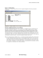
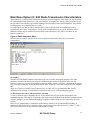
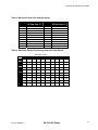
1
INDUSTRIAL DATA COMMUNICATIONS USER GUIDE PlantLinc™ 5000 PLR5000 Industrial Frequency Hopping Spread Spectrum Radio Modem It is essential that all instructions contained in the User Guide are followed precisely to ensure proper operation of equipment. Product User Guide FCC Notification This device complies with part 15 of the FCC rules. Operation is subject to the following conditions: 1) 2) This device may not cause harmful interference and This device must accept any interference received, including interference that may cause undesired operation. The device must be operated as supplied by Data-Linc Group. Any changes or modifications made to the device without the express written approval of Data-Linc Group may void the user’s authority to operate the device. Caution: This device has a maximum transmitted output power of 200 mW. It is required that the transmit antenna be kept at least 23 cm away from nearby persons to satisfy FCC RF exposure requirements. Note: This equipment has been tested and found to comply with the limits for a Class A digital device, pursuant to part 15 of the FCC Rules. These limits are designed to provide reasonable protection against harmful interference in a industrial installation. This equipment generates, uses and can radiate radio frequency energy and, if not installed and used in accordance with the instructions, may cause harmful interference to radio communications. However, there is no guarantee that interference will not occur in a particular installation. If this equipment does cause harmful interference to radio or television reception, which can be determined by turning the equipment off and on, the user is encouraged to try to correct the interference by one or more of the following measures: Reorient or relocate the receiving antenna. Increase the separation between the equipment and receiver. Connect the equipment into an outlet on a circuit different from that to which the receiver is connected. Consult the dealer or an experienced radio/TV technician for help. Note: Whenever any Data-Linc Group PLR series modem is placed inside an enclosure a label must be placed on the outside of that enclosure which includes the modem’s FCC ID. The following antennas are approved for use with Data-Linc Group’s 900 MHz series modems. NOTE: Per FCC Rules, the maximum power allowed at the antenna is 4 Watts E.I.R.P. 900MHz Directional Antenna Gain Manufacturer 8.2 dBi Larsen 12.2 dBi Larsen Manufacture Model Number YA6-900W YA0006 Data-Linc Model Number A-YB A-Y10B 900MHz Omni-Directional Antenna Gain Manufacturer 5.2 dBi Maxrad 7.2 dBi Maxrad 0 dBi Ying Hao 0 dBi Centurion Manufacture Model Number MAX-9053 BMEFC8985HD YH920801/AD-725-A-1 EXC-902-BN Data-Linc Model Number A-OB A-O5B A-06/ADJ A-06BH-3S / 10S (**) (**) This part number refers to an antenna kit(s). The 0 dBi refers to the antenna portion of the kit. Note: The antenna used for this device must be professionally installed on a fixed-mounted permanent outdoor structure for satisfying RF exposure requirements, including antenna co-location requirements of 1.1307(b)(3). DATA-LINC GROUP PN 161-09888-001 PlantLinc PLR5000 User’s Guide Table of Contents Page Introduction ..................................................................................................................................3 Loop Back Bench Test.................................................................................................................3 PLR5000 Modem Configuration...................................................................................................5 Main Menu Option (0): Set Operation Mode .......................................................................6 Main Menu Option (1): Set Baud Rate ................................................................................8 Main Menu Option (2): Edit Call Book.................................................................................9 Main Menu Option (3): Edit Radio Transmission Characteristics......................................12 Main Menu Option (4): Show Radio Statistics...................................................................16 Main Menu Option (5): Edit Multipoint Parameters ...........................................................18 Using an External Antenna ........................................................................................................21 Modem Front Panel LEDs..........................................................................................................22 Sample Data Communication Links...........................................................................................23 Technical Specifications ............................................................................................................25 Troubleshooting .........................................................................................................................26 Technical Support ......................................................................................................................28 Return Material Authorization ....................................................................................................28 Contact Information....................................................................................................................28 Appendix A: PLR5000 Modem Enclosure Diagram ...................................................................29 P/N 161-09888-001 DATA-LINC Group 1 PlantLinc PLR5000 User’s Guide P/N 161-09888-001 DATA-LINC Group 2 PlantLinc PLR5000 User’s Guide Introduction The PLR5000 transceiver modems are high performance wireless radio modems designed for heavy-duty industrial data communications in the 902-928 MHz license-free band. It employs advanced spread spectrum frequency hopping and error detection technology to achieve very reliable, noise and interference immune operation. An RF data rate of 38.4 Kbps and superior sensitivity provide ultra reliable data integrity at data rates from 1200 to 38.4 Kbps. Full duplex operation at data rates up to 19.2 Kbps provide the fast response times needed for polling communications. The PLR5000 has a range of up to 4 miles (6.5 km) with line-ofsight and an omni directional antenna. The PLR5000 can be operated in a number of different modes to satisfy a broad range of communications requirements. It can be configured for point-to-point or multipoint operation with a unlimited number of remote sites on a single Master depending on data throughput requirements. Repeaters can be used in the system to eliminate dead RF zones that are blocked by obstructions. External antennas can be used with up to one hundred feet of coax. With external antennas, radio modems can be located inside buildings or metallic enclosures. The PLR5000 will operate in virtually any environment where RS232 data communications are required. The transceiver RS232 interface is a standard DB9-F connector that is configured for Data Communications Equipment (DCE) operation. The PLR5000 will connect with a straight through RS232 cable to a device configured for Data Terminal Equipment (DTE) operation. The user guide covers the operating modes and configurations that are available to users of the PLR5000. It also provides the user with bench testing instructions, technical information and specifications for the PLR5000. In most applications, the PLR5000 radios come from Data-Linc Group pre-configured for the application in which they are going to be used. Generally, no other configuration is required. If you are unsure if the modem needs further configuration, please contact Data-Linc Group. Loop Back Bench Test This procedure provides a simple and easy demonstration of proper operation of the Data-Linc Group PLR5000 radio modems. The Loop Back Bench Test should be conducted to ensure system functionality prior to actual installation, and to allow the installer to become familiar with operation of the radio modems. A few minutes on the bench can save time in the field. 1. The PLR5000 radios that you have received are typically pre-configured by Data-Linc Group to function as a system. No changes in configuration should be made with out first consulting the factory. 2. Attach the bench test antenna included with the radio modem. 3. Locate the PLR5000 labeled “MASTER.” Using a standard RS232 cable, connect the radio modem to a communication port on a computer that has a communications utility such as HyperTerminal, ProComm Plus or Terminal for Win3.x. Set the data rate (BPS) of the terminal program to match the port rate of the PLR5000 Plug the power supply into an AC outlet of the correct voltage, and connect the power supply to the PLR5000. The red LED marked “P” (power) on the radio modem front panel should turn on. P/N 161-09888-001 DATA-LINC Group 3 PlantLinc PLR5000 User’s Guide 4. If your system is configured to use a Repeater(s), find the PLR5000(s) marked “REPEATER,” and connect its power supply as with the Master above. The red LED marked “P” (power) on the radio modem should turn on. If your system does not have a Repeater, skip this step. 5. Locate the PLR5000(s) labeled “REMOTE.” Connect the power supply to the PLR5000. The red LED marked “P” (power) on the “REMOTE” radio modem should turn on. If it is a point-to-point system the amber LED “C” (carrier detect) should turn on for both the Remote and Master. If it is a point-tomultipoint system the “C” LED will turn on for the Remote only. Attach a Loop Back Test Jumper on the RS232 data DB9F connector of the PLR5000 remote. The jumper shorts pins 2 and 3 of the data connector. 6. Using the terminal that is connected to the “MASTER” PLR5000, hold down a key, “A” for example. The letter “A” should begin to scroll across the terminal screen. This indicates that the data (the letter “A” in this case) is being transmitted from the terminal through the “MASTER” PLR5000. Then through the “REPEATER” (if applicable), on to the “REMOTE” PLR5000, through the Loop Back Test Jumper, back through the “REPEATER” (if applicable) to the “MASTER,” and then the terminal. This establishes that the PLR5000s are functioning in full duplex mode and are operating properly. Note: If something appears scrolling across the terminal screen other than the correct character for the key being pressed, it indicates that the terminal’s settings and data rate may not be set to match that of the PLR5000. 7. While continuing to press the letter “A,” the yellow LED marked “I” (Input) and the green LED marked “O” (Output) should both be flashing rapidly on the Master radio modem and the Remote with the jumper attached. Remove the jumper from the “REMOTE” radio modem. The letter display scrolling across the screen should stop, and the “O” LED will stop flashing at the “MASTER.” The “I” LED will flash each time the key is pressed; indicating that the radio modem is receiving a data input signal on the RS232 port. The “O” LED on the “REMOTE” will flash each time a key is pressed; indicating that the radio modem is outputting a data input signal on the RS232 port. The “I” LED on the “REMOTE” will remain off with no data Loop Back . Replace the Loop Back Test Jumper in the “REMOTE” radio modem. Hold down the key again, and the letter should once again scroll across the computer screen. If there is a “REPEATER” in the system its “C” (carrier detect) LED will flash rapidly when data is being passed. The “REPEATER” “I” and “O” LED’s remain off during normal operation. Repeat steps 5 through 7 with each of the “REMOTE” units for your system. Data-Linc Group strongly recommends that once these tests have been successfully completed, all devices that will be used in the system (PLC, RTU, software, computers, etc.) be connected to the system and bench tested to assure full functionality before final installation. If the radios will not function in the system on the bench, remove the radio modems from the system and confirm that the equipment will communicate with a direct hard wire link. If the devices will not communicate directly without the radio modems, then they will not communicate with them. The radio modems emulate a direct asynchronous communication link. Once the preceding bench tests have established that the system is fully functional, site installation should proceed. However, before connecting the entire system hardware, Data-Linc Group recommends that steps 3 through 7 above be performed on-site to confirm radio modem operation and adequate line of sight between the antennas. P/N 161-09888-001 DATA-LINC Group 4 PlantLinc PLR5000 User’s Guide PLR5000 Modem Configuration The PLR5000 allows you to set several parameters to suit your particular application. All adjustments are done through the PLR5000 setup program, a user interface that eliminates the need for setup diskettes, DIP switch settings or custom software. To access the configuration menu, connect the radio modem to any terminal program with port settings of 19.2Kbaud, 8 data bits, no parity and one stop bit. With the modem connected to the PC running the terminal program, press the Configure button located behind the pinhole next to the DB-9 connector on the front of the modem. While any terminal program that can be set to 19200 baud will work, examples for this user guide were generated using the Microsoft Windows 2000 application “HyperTerminal.” Note: When using HyperTerminal, set Handshaking to none. Table 1:Terminal Settings Parameter Setting Baud Rate 19200 Data Bits 8 Parity None Stop Bits 1 Flow None Control When the setup program is invoked, the “O” LED on the PLR5000 front panel will flash once when the Configure button is pressed and the “C” LED will remain on for the entire time the radio modem is in setup mode. The main menu provides the radio modem’s unique call book number and the set of choices for editing the operational parameters and viewing the performance data. Figure 1: Main Menu P/N 161-09888-001 DATA-LINC Group 5 PlantLinc PLR5000 User’s Guide Main Menu Option (0): Set Operation Mode When item (0) is selected, the Operation Mode Menu appears as shown in Figure 2. The Operation Mode option is used to designate the method in which the particular PLR5000 will be used. The PLR5000 operates in a Master to remote configuration; therefore, any radio modems that are intended to operate together must be set up as such. In a point-to-point setup, either the Master or Remote may be used on either end of the communications link. One consideration when setting up the radio modems is that a number of parameters are controlled by the settings in the Master; therefore, you may wish to deploy the Master on the communications end where you will have easier access to the radio modem. Figure 2: Mode Menu Shown below are example settings. Please refer to configuration sheets supplied for your modem’s configuration. (0) Point-to-point Master The PLR5000 operates in a Master/remote configuration. When designated as a Master in point-to-point mode, the radio modem will call any or all Remotes it is instructed to call in the call book. The Master determines the settings used for all Radio Transmission Characteristics, regardless of the settings in the Remotes and/or Repeaters. (1) Point-to-Point Remote When set up as a point-to-point Remote, a PLR5000 will communicate with any Master in its call book, either directly or through one or two Repeaters. When functioning as a Remote, the Entry to Call feature in the radio modem’s call book (Figure 3) is not operational. The Remote will communicate with any Master on the list that calls. (2) Point-to-Multipoint Master The PLR5000 may be set to run in multipoint mode, which allows one Master to simultaneously be in communication with numerous Remotes. A point-to-multipoint Master will communicate only with other radio modems designated as point-to-multipoint Remotes or point-to-multipoint Repeaters. (3) Point-to-Multipoint Remote Setting (3) allows the radio modem to operate as a Remote in a multipoint network. Please refer to the section entitled multipoint Operation, for more information on running a multipoint network. P/N 161-09888-001 DATA-LINC Group 6 PlantLinc PLR5000 User’s Guide (4) Point-to-Point Remote/Repeater Option 4 allows you to designate the radio modem to act as either a Remote or a Repeater, depending upon the instructions received from the Master for the specific communications session. When a radio modem is placed in an ideal location, this setting offers the flexibility of using that radio modem as an end-point in the communications link (Remote) or to extend the link to a point further (Repeater). These functions are not, however, available simultaneously (the radio modem cannot act as both a Remote and a Repeater at the same time). A word of caution: Configured as a Repeater, a radio modem has no security features as explained below. When a radio modem is designated as a point-to-point remote/Repeater, it will allow any Master to use it as a Repeater. (5) Point-to-Point Repeater PLR5000 radio modems allow the use of up to two Repeaters in a communications link, significantly extending the operating range. When designated as a Repeater, a radio modem behaves as a pass-through link. All settings for the call book, baud rates, and radio transmission characteristics are disabled. A Repeater will connect with any Master that calls it (the Repeater must still be set up in the Master’s call book). The use of one Repeater in a communications link will reduce the top data throughput available when compared to a direct Master to remote link (generally on the order of 50%). This impact is generally noticed only when using the radio modems at 38.4 Kbaud. The throughput does not decrease further if two Repeaters are used. (6) Point-to-Point Remote/Master Switchable Mode 6 is a versatile option that allows the radio modem to be controlled entirely through software commands. When in mode 6, a number of key parameters in the radio modem’s user interface may be changed either directly (as if using the Windows Terminal program) or by using script files. In addition, when the radio modem is in mode 6 and not calling a Remote, it will be a Remote itself and accept any appropriate calls from other radio modems. In mode 6: • The radio modem remains in remote mode until called by another radio modem in its Call Book or instructed to call another radio modem through an ATDT command. The Master will disconnect when DTR goes low.. • The user may change settings in the user interface without using the reset button (this may be of particular value if the radio modem is not in an easily accessible location). • Predetermined script files may be used which allow some of the radio modem’s settings to be changed upon execution of that file. This, in turn, allows the user to establish command sets that will instruct the radio modem to call a predetermined remote. Note: For a detailed explanation covering the features of Mode 6, please contact the factory. (7) Point-to-Multipoint Repeater Setting (7) allows the radio modem to operate as a Repeater in a multipoint network. Please refer to the section titled, “Multipoint Operation”, for more information on running a multipoint network. P/N 161-09888-001 DATA-LINC Group 7 PlantLinc PLR5000 User’s Guide Main Menu Option (1): Set Baud Rate When option (1) is selected, you will be able to change the radio modem’s RS232 baud rate. This is the communication rate between the radio modem and the instrument to which it is connected. It is important to note that this is independent of the baud rate for the other radio modem(s) in the communication loop. For example, PLR5000s may be used in an application to send data from remote process instrumentation to an engineer’s computer. In this application, the baud rate for the radio modem on the instrumentation might be set to 9600, and the radio modem on the computer might be set to 19,200 or 38,400. In general, it is desirable to set the baud rate to the highest level supported by the device to which it is connected. However, please note that this may actually result in slower data communications if the UART chipset of the connected device does not support higher data rates. ModBus RTU and various data word sizes and parity configurations The additional features are support for ModBus RTU and support various data word lengths and parity. These features are available under selection options (A) and (B). There are six data word length and parity configurations available. In the Set Baud Rate menu select (A) and type in the number corresponding to the configuration below. The default setting is 0 (8,N,1) and is the most commonly used serial communications protocol. Table 2: Available data word length and parity selections Menu Setting 0 1 2 3 4 5 Data Bits 8 7 7 8 8 8 Parity None Even Odd None Even Odd Stop Bits 1 1 1 2 1 1 ModBus RTU Support for ModBus RTU protocol is available. The default for the ModBus RTU setting is (0) not enabled. To enable the ModBus RTU mode: 1. In the “Set Baud Rate” menu enter (B) and then select (1) 2. In the “Set Multi Point Parameters” menu, set Master Packet Repeat to (3). Note: When using the PLR5000 radios in ModBus RTU mode the Master Packet Repeat must be set to (3) regardless of whether the modems are being used in point-to-point or multipoint mode. If a setting that is higher than (3) is required, it can be done, but the throughput speed will be decreased. (A higher Master Packet Repeat setting may need to be used when the radios are in a high noise environment or at long ranges). P/N 161-09888-001 DATA-LINC Group 8 PlantLinc PLR5000 User’s Guide Main Menu Option (2): Edit Call Book The Call Book is an innovative feature in the PLR5000 that offers both security and flexibility in use. The Call Book accomplishes this by allowing the user to determine with which other PLR5000s a given radio modem will communicate, based on the Call Book numbers for both the Master and remote. The radio modem’s Call Book number is encoded in the microprocessor and identified on a label on the modem. The instructions provided in this section are for point-to-point mode only. Use of the Call Book for multipoint systems is explained later in this chapter. For two PLR5000 radio modems to communicate in point-to-point mode, three events must occur: 1. The call book number for the Master must be listed in the Remote’s Call Book. 2. The call book number for the Remote must be listed in the Master’s Call Book. 3. The Master must be programmed to call the Remote. As shown in Figure 3, the Call Book allows users to set up a list of up to 10 PLR5000s with which to communicate. Designate up to 2 Repeaters to be used in communicating with a given radio modem, and tell the Master which Remote to call. To direct the Master to call a Remote, the Remote must be in the Call Book Menu. A specific remote may be called by entering (C) at the prompt, followed by the menu number corresponding to that remote. To call any available remote in the list, the user should enter C and then A (for All). Note: To call a Remote through one or two Repeaters, you must call that remote directly (as opposed to using the Call All option). When Call All is selected the Master is not able to connect with any Remotes through Repeaters. This is because the Master calls every remote in the list when instructed to call all and will connect with the first remote to respond. When calling through a Repeater, the Master must first call that Repeater and establish a communications link with it prior to making contact with the Remote. P/N 161-09888-001 DATA-LINC Group 9 PlantLinc PLR5000 User’s Guide Figure 3: Call Book Menu Shown below are example settings. Please refer to the supplied configuration sheets for your modem’s configuration. Entering or Modifying Numbers in the Call Book Entering or modifying call book numbers in the Call Book is a straightforward process. When in the Call Book menu, select the entry number (0 – 9) you wish to edit. You will be prompted for the new number (formatting is automatic, you do not need to enter the dash). Once the number is entered (unless it is 0000000), you will be asked for the call number of the first Repeater to be used. If no Repeater is to be used, enter the escape key; your entry will be complete and you will be back in the Call Book menu screen. If you enter a Repeater number, you will then be prompted for the call number of the second Repeater to use. If a second Repeater is being used, enter the call number at this time; if not, enter the escape key. Once again, the radio modem will retain your entries, as shown in the updated Call Book menu screen. Note: It is important that the Call Book slots (0 – 9) are filled sequentially beginning with 0, the first slot in the book. Call Book numbers do not need to be entered in numerical order; however, there must not be any 000-0000 numbers in the middle of the list of good Call Book numbers. The reason for this is that when a Master is instructed to Call All available Remotes, it will call all Remotes listed until it reaches the first number of 000-0000. If a valid call book number is entered after the all zero number, it will not be recognized as a valid number to be called by the Master. P/N 161-09888-001 DATA-LINC Group 10 PlantLinc PLR5000 User’s Guide Edit Call Book in Multipoint Systems In a multipoint system, the Remotes and Repeaters are not listed in the Master’s Call Book. When establishing such a system, it is necessary only to have the Master’s Call Book number in each Remote’s and Repeater’s Call Book, and to have each Repeater’s Call Book number in the Call Book of each Remote which may potentially communicate through it. The following example shows the Call Books of a multipoint system comprised of a Master, Repeater and remote in which the Remote can communicate either through the Repeater or directly to the Master: Multipoint Master Call Book (Unit Call Book number 555-0001) Entry (0) (1) Number 000-0000 000-0000 Repeater 1 Repeater 2 No call book number entries are necessary in the Master’s Call Book. The Master’s Call Book may be programmed to call any entry. Multipoint Repeater Call Book (Unit Call Book number 555-0002) Entry (0) (1) Number 555-0001 000-0000 Repeater 1 Repeater 2 Multipoint Remote Call Book (Unit Call Book number 555-0003) Entry (0) (1) (2) P/N 161-09888-001 Number 555-0001 555-0002 000-0000 Repeater 1 Repeater 2 DATA-LINC Group 11 PlantLinc PLR5000 User’s Guide Main Menu Option (3): Edit Radio Transmission Characteristics When option (3) is selected in the main menu, the screen in figure 4 appears, which allows the user to modify the radio transmission characteristics of the radio modems. As stated in the warning, these parameters are for the experienced user who has a good understanding of the principles of radio data transmission. They should be changed only after consulting this user guide. It is important to note that the radio parameters between any radio modems in communication will be determined by the settings for the Master (except when in multipoint mode, see (4) RF Data Rate below). While the settings may be modified for the Remote(s) and/or Repeaters, they will be overridden by the Master’s parameters. Figure 4: Radio Parameters Menu Shown below are example settings. Please refer to supplied configuration sheets for your modem’s configuration. (0) FreqKey Selection (0) in the Radio Parameters menu allows the user to modify the hopping patterns of the radio modems to minimize the interference with other PLR5000 radio modems in operation in the area. For instance, if there were 10 pairs of PLR5000s in operation within a factory or refinery, changing the Frequency Key would ensure that they would not jump onto the same frequencies at the same time for the same length of time. There are 15 choices available for the Frequency Key (0-9 and A-E). It is recommended that a list be maintained of the settings for each Master to ensure that each is set to a different hopping pattern. (1) Max Packet Size and (2) Min Packet Size Selections (1) and (2) allow the user to designate the size of the packets (in bytes) used by the radio modem in its communication link. This may be of particular value when using the PLR5000 with different communications software packages; you may find that throughput is optimized when packet sizes are restricted by the radio modem. Packet size is determined by a combination of the settings entered by the user and the RF Data Rate. In addition, the Max Packet Size is a function of the setting selected for the Min Packet Size. Tables 2, 3 and 4 provide the packet sizes for each different combination of settings. P/N 161-09888-001 DATA-LINC Group 12 PlantLinc PLR5000 User’s Guide Table 3: Minimum Packet Size Settings (bytes) Setting 0 1 2 3 4 5 6 7 8 9 Min Packet Size RF Data Rate =2 16 21 26 32 37 42 48 53 58 64 Setting 0 1 2 3 4 5 6 7 8 9 Min Packet Size RF Data Rate =3 8 12 16 20 24 28 32 36 40 44 Table 4: Maximum Packet Size Settings where RF Data Rate=3 0 1 2 3 4 5 6 7 8 9 P/N 161-09888-001 0 8 12 16 20 24 28 32 36 40 44 1 24 28 32 36 40 44 48 52 56 60 Maximum Setting 2 3 4 5 40 56 72 88 44 60 76 92 48 64 80 96 52 68 84 100 56 72 88 104 60 76 92 108 64 80 96 112 68 84 100 116 72 88 104 120 76 92 108 124 6 104 108 112 116 120 124 128 132 136 140 7 120 124 128 132 136 140 144 148 152 156 DATA-LINC Group 8 136 140 144 148 152 156 160 164 168 172 9 152 156 160 164 168 172 176 180 184 188 13 PlantLinc PLR5000 User’s Guide Table 5: Maximum Packet Size Settings where RF Data Rate=2 0 1 2 3 4 5 6 7 8 9 0 15 20 26 31 36 42 47 52 58 63 1 36 42 47 52 58 63 68 74 79 84 Maximum Setting 2 3 4 5 58 79 100 121 63 84 105 127 68 90 111 132 74 95 116 137 79 100 121 143 84 105 127 148 90 111 132 153 95 116 137 159 100 121 143 164 95 127 148 169 6 143 148 153 159 164 169 175 180 185 190 7 164 169 175 180 185 190 196 201 206 212 8 185 190 196 201 206 212 217 222 228 233 9 206 212 217 222 228 233 238 244 249 254 (3) Xmit Rate There are two settings for the Transmit Rate parameter. For normal operation, the PLR5000 should be set at Transmit Rate 1. Transmit Rate 0 is useful to qualitatively gauge signal strength. When set to Transmit Rate 0 the radio modems will transmit data back and forth continuously, and the strength of the signal may be gauged by viewing the Show Radio Statistics option. Because the radio modems transmit continuously when Transmit Rate is set to 0 (whether or not they have data to send) they use radio frequency spectrum unnecessarily. Therefore, Transmit Rate 0 should be used only as a diagnostic tool and not for normal operation. (4) RF Data Rate The PLR5000 has two settings for the RF Data Rate (not to be confused with the RS232 Baud Rate). Setting 2 (50.1 Kbps) should be used when the radio modems are close together and data throughput is to be optimized. Setting 3 (38.4 Kbps) should be used when the radio modems are farther away and a solid data link is preferred over data throughput. Note: The RF Data Rate setting must be identical for all units in the system. Any radio modem with a different RF Data Rate than the Master will not establish a communication link. P/N 161-09888-001 DATA-LINC Group 14 PlantLinc PLR5000 User’s Guide (5) RF Xmit Power The PLR5000 offers users the ability to modify the Transmission Power of the radio modem. There are 10 power settings available (1-10) which are roughly linear. Therefore a setting of 10 is full power (or 200 mw) and 1 is 10% power (or 20 mw). For most application power level should be set to 10. (6) Remote Security With option 6 the user may disable the radio modem’s security so it will accept a call from any other PLR5000. The default setting is 0 where security is enforced (the caller’s call book number must be in the Remote’s Call Book). With a setting of 1 security is disabled. As mentioned in mode 6, Remote Security must be set to 1 when the unit is operating in a point-to-point system where it may need to accept calls from more than 10 different PLR5000s. However, it is important to note that when Remote Security is set to 1, the radio modem will accept calls from any other PLR5000, and additional system security measures should be taken to prevent unauthorized access. (7) RTS to CTS Menu selection 7 in the Radio Parameters provides the option of allowing the RTS line (pin 7) on the Master radio modem to control the CTS line (pin 8) of the Remote. This pass-through control can be enabled in point-to-point mode as well as point-to-multi-point. In the latter, the Master RTS line will control all Remotes’ CTS lines. When this mode is enabled the CTS line ceases to function as flow control. To enable this mode, enter 7 in the Radio Parameters menu. An entry of (1) will enable the RTS-CTS control a (0) will disable it. (8) Retry Time Out The Retry Time Out parameter allows the use to determine when a Remote will drop a connection to a Master or Repeater in multipoint mode. The default setting is 255, therefore, if one packet in 255 from the Master is sent successfully to the Remote, it will maintain a link. The lowest setting is 8, which allows a Remote to drop a connection more quickly. The Retry Time Out parameter is useful when a multipoint system is used with a moving Master or Remotes. As the link gets weaker, a lower setting will allow a Remote to drop its link and search for a stronger connection. While intended primarily for multipoint systems, the Retry Time Out parameter may also be modified in point-to-point systems. In point-to-point mode the Retry Time Out should not be set to a value of less than 151. P/N 161-09888-001 DATA-LINC Group 15 PlantLinc PLR5000 User’s Guide Main Menu Option (4): Show Radio Statistics Option (4) in the main menu allows the user to view data transmission statistics, which have been gathered by the Transceiver during the most recent session. Statistics are gathered during each data link and are reset when the next link begins. Ideally, noise levels should be below 30, and the difference between the average signal level and average noise level should be 30 or more. High noise levels tend to indicate other sources of RF interference, while low signal levels indicate a weak link. The “Local” stats are the statistics that are being gathered by the modem you are connected to while “Remote1, Remote2, and Remote3” are the stats of the Repeater(s) that the modem you are attached to is using to get back to the Master modem. The following sections provide information useful to the process of troubleshooting and improving radio links. Average Noise Level The average noise level indicates the level of background noise and interference at this modem and at each of the modems used as Repeaters in the link. The number is an average of the noise levels measured at each frequency in the modems’ frequency hop table. The individual measurement values at each frequency hop channel are shown in the frequency table. The frequency table is accessed by pressing the ENTER key on the computer when the radio statistics menu is displayed. Average noise levels will typically fall in the range of 15 to 30. Average noise levels significantly higher than this are an indication of a high level of interference that may degrade the performance of the link. High noise levels can often be improved with bandpass filters, antenna placement or antenna polarization. Please contact Data-Linc Group for more information. Average Signal Level The average signal level indicates the level of received signal at this modem and at each of the modems used as Repeaters in the link. For each of these, the signal source is the modem that transmits to it. The number is an average of the received signal levels measured at each frequency in the modem’s frequency hop table. The individual measurement values at each frequency hop channel are shown in the frequency table. The frequency table is accessed by pressing the ENTER key on the computer when the radio statistics menu is displayed. For a reliable link, the average signal level should be at least 15 higher than the average noise level reading. Low Average Signal Levels can often be corrected with higher gain antennas, antenna placement, and use of Repeaters. Contact Data-Linc Group for more information. Overall Rcv Rate (%) The Overall Rcv Rate measures the percentage of data packets that were successfully transmitted from the Master to the Remote on the first attempt without requiring retransmission. A number of 75 or higher indicates a robust link that will provide very good performance even at high data transmission rates. A number of 25 or lower indicates a weak or marginal link that will provide lower data throughput. P/N 161-09888-001 DATA-LINC Group 16 PlantLinc PLR5000 User’s Guide Number of Disconnects If, during the course of performing a link test, the link between the Master and the Remote is broken, and the radios lose carrier detect, the occurrence is recorded in the Number of Disconnects value. The value indicates the total number of disconnects that have occurred from the time the link test started until the radio was put into config mode. Under normal operating conditions, the number of disconnects should be 0. One or more disconnects may indicate a very weak link, the presence of severe interference problems or loss of DC power to the Master or Repeater if one is present. Note: a Remote and/or Repeater will record a disconnect if the system Master is placed into configuration mode or has power interrupted while the Remote and/or Repeater is linked to the Master Radio Temperature The radio temperature value is the current operating temperature of the radio in degrees C (Celsius.) For proper operation, PLR5000 radio modems must be in the range of –40 to 750 C. Multipoint Operation In a multipoint system, a radio modem designated as a Master is able to simultaneously be in communication with numerous Remotes. In its simplest form, a multipoint network functions with the Master broadcasting its messages to all Remotes and the Remotes responding to the Master as appropriate. Traditionally, a multipoint network is used in applications where data is collected from many instruments and reported back to one central site. As such, the architecture of such a system is completely different from point-to-point applications. The theoretical maximum number of Remotes that can be configured into a multipoint network is a function of the data throughput needed from each of the Remotes. For example, if the network will be polling Remotes once a day to retrieve sparse data, several hundred Remotes could be configured to a single Master. If, on the other hand, each Remote will be transmitting data at greater levels then fewer Remotes may be connected to the Master (the overall system will be closer to capacity with fewer Remotes). The theoretical limit of a multipoint system is influenced by the following parameters: • Size of the blocks of data—the longer the data blocks the greater the system capacity • RS232 baud rate • The amount of contention between Remotes • Use of Repeaters—a single Repeater in a multipoint network will decrease overall system capacity by 50%; more than one Repeater does not further decrease network capacity. P/N 161-09888-001 DATA-LINC Group 17 PlantLinc PLR5000 User’s Guide Main Menu Option (5): Edit Multipoint Parameters Figure 5: Multipoint Parameters Shown below are example settings. Please refer to supplied configuration sheets for your modem’s configuration. In a multipoint network, it is critical to know how many radio modems are being used as Repeaters. Any radio modem that is used as a Repeater essentially becomes a Master to the Remotes and other Repeaters to which it is communicating. Therefore, the user must first identify how many Repeaters are connected to the Master by assigning a value in parameter (0) Number Repeaters. This parameter must also be set for each Repeater in the system (i.e., in the event that a Repeater is connected to one or more other Repeaters). This parameter does need to be set for multipoint Remotes. In point-to-point operation, the PLR5000 radio modems acknowledge every data packet transmitted. In a multipoint network, the Remotes do not acknowledge transmissions from a Master to the Remotes. This is to prevent system overload. If the Remotes acknowledged all data transmissions from the Master in a large multipoint system, then all system capacity would be spent having the Master listen for acknowledgments from the Remotes. Because the transmission is not acknowledged by the Remotes, 100% confidence does not exist that every remote has received every message from the Master. To address this issue, the user may modify option (1) Master Packet Repeat, assigning a value between 0 (the packet is transmitted once) to 9 (the packet is repeated 9 times). For networks with solid RF links, this parameter would be set at the lower end of the scale (0-1). If the network has some weak or marginal links, it would be set toward the higher values. If a Remote receives a packet from a Master more than once, it will discard the repeated packets. While packets transmitted from the Master to the Remotes in a multipoint network are not acknowledged, packets transmitted from Remotes to the Master are. However, it is possible that more than one remote will attempt to transmit to the Master at the same time, and it is therefore important that a protocol exists to resolve contention for the Master between Remotes. This is addressed through parameters (2) Max Remote Retry and (3) Retry Odds. The Max Remote Retry setting defines how many times (0 to 9) the Remote will attempt to retransmit a packet to the Master before P/N 161-09888-001 DATA-LINC Group 18 PlantLinc PLR5000 User’s Guide beginning to use a back-off algorithm. When the Remote has failed to transmit the packet the number of times specified in Max Remote Retry, it will attempt to transmit to the Master on a random basis. The Retry Odds parameter determines the probability that the Remote will attempt to retransmit the packet to the Master; a low setting will assign low odds to the Remote attempting to transmit and conversely a high setting will assign high odds. An example of how this parameter might be used would be when considering two different Remotes in a multipoint network, one close in with a strong RF link and the other far from the Master with a weak link. It may be desirable to assign a higher Retry Odd to the Remote with the weaker link to give it a better chance of competing with the closer remote for the Master’s attention. Another parameter in a multipoint network is (4) DTR Connect. When set at (1), the Remote will connect to the Master if it is free when the DTR line goes high on the 9-pin RS232 connector. In setting (2), the radio modem will accumulate data in its buffer and transmit in a burst when the buffer is full. This mode is valuable when a network has many low data rate devices and it is desirable to increase overall network capacity. In setting (0), the radio modem will transmit when RS232 data is received. The Repeater’s hopping pattern must also be set in a multipoint network; this is accomplished with parameter (5) Repeater Frequency. Setting this parameter is in contrast with point-to-point mode where the Repeater automatically uses the Master’s hopping pattern. The Repeater may be programmed to either use the Master’s hopping pattern selection (0) or its own selection (1). Option (6) NetWork ID allows multipoint networks to be established without the use of the Call Book. If the NetWork ID is set to any value lower than the default (255), the Remotes in the multipoint network will communicate with the first multipoint Master or Repeater heard with the same NetWork ID. When the NetWork ID is used, multipoint Masters and Repeaters may be replaced without reprogramming all of the Remotes in the network. In addition, this allows a Remote to establish communications with different Masters (though not at the same time) without having the call book numbers in the Call Book. This is very useful in mobile multipoint applications. Option (8) Remote/Repeater mode allows a PLR5000 in a multipoint system to simultaneously act as a Remote and a Repeater. When in this mode, a PLR5000 will repeat any packets sent from a Master as well as send them out the RS232 port. This allows a PLR5000 set as a Repeater to act as a Remote at the same time. 0 disables this mode, 1 enables it. For this feature to work, the modem must be configured as a point-tomultipoint Repeater. P/N 161-09888-001 DATA-LINC Group 19 PlantLinc PLR5000 User’s Guide SubNet ID The PLR5000 series modems offer a SubNet ID system for use in multipoint networks using Network ID. This feature allows the users to dictate what path a given Repeater or remote will use to achieve a link to the network Master. For example, if a Remote modem in a given network has line of sight to the network Master and one or more Repeaters, but only one Repeater is close to that remote, SubNet ID can be used to link that Master with the proper Repeater only. Note: This feature can only be used in networks using Network ID with one or more Repeaters. There are two components to SubNet ID. The first is the Xmit (transmit) SubNet ID, and the second is Rcv (receive) SubNet ID. The Xmit SubNet ID is used only by Repeaters and is the ID that a Repeater sends out when sending data to other Repeaters or Remotes. The Rcv SubNet ID is the ID that Repeaters or Remotes look for to receive data. Note: The Master is not affected by these settings. Only Repeaters and Remotes use these settings. Remotes only use Rcv SubNet ID Modem configurations are as follows (see Diagram 1 below): Master No setting used Repeaters Any Repeater that should be linked directly to the Master should have the Rcv SubNet ID set to 0. Any Repeater using another Repeater as its link, needs the Rcv SubNet ID set to the Xmit SubNet ID of that Repeater. The Xmit SubNet ID can be set to anything from 1 to E. Remotes Any remote that should be linked directly to the Master should have the Rcv SubNet ID set to 0. Any remote using a Repeateras its link should have the Rcv SubNet ID set to the Xmit SubNet ID of that Repeater Diagram 1: Modem configurations P/N 161-09888-001 DATA-LINC Group 20 PlantLinc PLR5000 User’s Guide PLR5000 Location Placement of your PLR5000 is likely to have a significant impact on its performance. In general, the rule of thumb with the PLR5000 is that the higher the placement of the antenna, the better the communication. In practice, you should also place the radio modem itself away from computers, telephones, answering machines, and other similar equipment. A 6-foot RS232 cable will usually provide ample room for placement away from other equipment. To improve the data link, Data-Linc Group offers directional and omni directional antennas with cable lengths ranging from 10 to 200 feet. When using an external antenna, placement of that antenna is critical to a solid data link. Other antennas in close proximity are a potential source of interference. It is also possible that slight adjustments in antenna placement (as little as 2 feet) will solve noise problems. In extreme cases, such as when the radio modem is located close to pager or cellular telephone transmission towers, Data-Linc Group offers a band pass filter to reduce the out of band noise. Using an External Antenna In certain circumstances, it may be desirable to extend the range of the PLR5000 radio modem by using an external antenna in place of the standard whip antenna. The radio modem is equipped with a standard SMA external jack. This allows the use of external omni directional or yagi antennas. These are part of kits provided by Data-Linc Group and include coax cable. These antennas allow versatility in the PLR5000’s deployment, extending its range and allowing it to get around obstructions. The use of an external antenna may radically improve the results obtained with PLR5000 radio modems. It is imperative to obtain line of sight with the antennas, and changes in placement height of as few as a couple of feet may make the difference between no link and one that is solid and reliable. If external directional antennas are used, FCC regulations concerning effective radiated power limitations must be followed. Caution: Any antenna placed outdoors must be properly grounded. It is required by FCC regulations that qualified personnel experienced in antenna installation and familiar with local codes and regulations complete the antenna installation. It is also required by FCC regulations that only approved antennas be used. Use extreme caution when installing antennas and follow all instructions included with the antennas. The use of an external antenna subjects the radio modem to greater exposure to direct lightning strikes. It is strongly recommended that a lightning arrestor be used on all outdoor antenna installations. Long RS232 cable runs should also be avoided in areas with increased lightning activity or static electricity unless they are properly isolated from the radio modem. Nearby lightning strikes or elevated levels of static electricity may lead to voltage spikes on the line, causing failure in the radio modem’s RS232 interface. It is also recommended that the RS232 data cable not be located near high voltage power lines as this can cause interference in data communications, damage the PLR5000 as well as an increase in risk of personal injury. P/N 161-09888-001 DATA-LINC Group 21 PlantLinc PLR5000 User’s Guide PLR5000 Front Panel LEDs The LEDs on the PLR5000’s front panel provide important information the of the radio modems. Compare the status of a radio modem’s LEDs with the tables below to aid you in the troubleshooting process SR FA FY FG MG O SA Solid Red Flashing Amber Flashing Yellow Flashing Green Momentary Green Off Solid Amber Table 6: LED Status in Point-to-Point P=power C=carrier detect I=data in Configuration LED Indicators Powered, no RF link RF link established Data flow Master to Remote Data Remote to Master Configuration mode Master P O=data out Remote C I O SR O O SR SA O P C I O O SR O O O SR O O O O SR SA O O SR O O O C I O SR SA O FG SR SA O O SR SA O FG SR SA FY O SR SA O O SR SA O MG SR SA O MG SR SA O MG Configuration P/N 161-09888-001 P SR SA FY O Table 7: LED Status in Point-to-Multipoint P=power C=carrier detect I=data in LED Indicators Powered, no RF link RF link established Data flow Master to Remote Data Remote to Master Configuration mode Repeater Master P O=data out Remote C I O SR O O SR O O P Data out LED lights momentarily when the configuration button is depressed. Repeater C I O O SR O O O SR SA O P C I O O SR O O O O SR O O O SR FA FY O SR SA O FG SR SA O O SR FA O FG SR SA FY O SR SA O O SR FA O MG SR SA O MG SR SA O MG DATA-LINC Group Data out LED lights momentarily when the configuration button is depressed. 22 PlantLinc PLR5000 User’s Guide Table 8: RS232 Pin Assignments Pin 1 2 3 4 5 6 7 8 9 Assignment Carrier Detect Transmit Data Receive Data DTR Ground Data Set Ready RTS Clear to Send N/C 7 6 1 2 9 8 3 4 5 DB-9 Female Sample Data Communication Links The PLR5000’s versatility allows data communication links to be established using a variety of different configurations. This, in turn, makes it possible to extend the range of the PLR5000 and communicate around obstacles. Diagram 2 shows the most common and straightforward link, a Master communicating to a Remote in a dedicated link. Diagram 2: Point-to-Point Communication P/N 161-09888-001 DATA-LINC Group 23 PlantLinc PLR5000 User’s Guide Diagram 3 depicts how a link might be set up using a Repeater. The Repeater may be sitting on a hilltop or other elevated structure to link the Master to the Remote. In this setup, it may be desirable to use an external omni directional antenna on the Repeater; to extend the range Yagi antennas could be used on either or both of the Master and remote. Diagram 3: Point-to-Point with Repeater When a Repeater is used, the RF speed is cut in half, making 38.4 Kbaud uncompressed throughput unachievable. The baud rate, however, may still be set at 38.4. Diagram 4 depicts an example of a point-to-multipoint system. In this example, any data sent from the Master is broadcast to all three Remotes, two of which receives it through a multipoint Repeater. The data is in turn sent out of the RS232 port of each of the three Remotes. Diagram 4 P/N 161-09888-001 DATA-LINC Group 24 PlantLinc PLR5000 User’s Guide Technical Specifications Range* Rated*: 4 miles (6.5 km) RS232 Data Throughput (uncompressed)** 1200 Baud - 38.4 Kbaud RS232 Interface Asynchronous, full-duplex System Gain 129 dB Minimum Receiver Decode Level -106 dBm @ 10-6 raw BER Operating Frequency 902-928 MHz Modulation Type Spread Spectrum, GFSK Spreading Code Frequency Hopping Hop Patterns 15 (user selectable) RF Data Rate 38.4 Kbps / 50.1 Kbps Output Power 200 mW maximum (+23 dBm) Error Detection 32 Bit CRC with packet retransmit Antenna Power Requirements Bench test whip provided. Standard SMA connector allows use of external directional or omni directional antennas 10.5-18 VDC Power Consumption*** 550 mA Transmit, 200 mA Receive Connector RS232 9 pin female. 9 pin male to 9 pin female straight Unit Address Unique, factory set Operating Modes Point-to-Point Point-to-Multipoint Store-and-Forward Operating Environment -40 to +1670 F (-200 to +750 C) Point-to-Point Switchable * Line-of-sight distance using omni directional antennas ** Throughput measured assuming 75% frequency availability *** The true power consumption is impacted by the amount of data being sent. P/N 161-09888-001 DATA-LINC Group 25 PlantLinc PLR5000 User’s Guide Troubleshooting “I have two radio modems, one configured as a Master and the other as a Remote. When they are plugged in, the LEDs indicate they are receiving power, and yet they will not connect. Why not?” There are several reasons why this may occur: 1. The radio modems are running at full power and are too close to each other. If the radio modems are within 5-10 feet of each other and will not link, try either reducing the RF power to 0 on each or moving one unit to another room. (This problem occurred on the initial generation of product with the 555-call book number prefix. It has been addressed in radio modems with call book numbers 556 and higher). 2. The radio modems are not in each other’s Call Books. 3. The number of the Remote is in the Master’s Call Book, but the Master’s menu is not set to call that number. 4. The Master is set to Call All and a setting of 000-0000 precedes the number of the radio modem with which you are trying to communicate. “I am able to link to a Remote unit within line of sight when the PLR5000 I have is outside. However, as soon as I walk inside with it I lose the link, even if I place the radio modem by the window which faces the Remote unit.” Many modern buildings use energy efficient glass that wreaks havoc on RF signals. This glass contains a metal film that is very effective in blocking all radio waves. If your situation is as described above, the preferable solution is to install an antenna outdoors. “I have several radio modems set up to communicate with each other in a point-to-multipoint mode, yet they are not establishing contact.” In a multipoint system, there are two critical parameters, which must be set correctly to establish a communications link: 1. The Remote’s Call Book must contain the call book number or Network ID of the Master and/or Repeaters to which it will be communicating. 2. All radios must be set to run at the same RF data rate. Remote modems must match the Masters RF data rate. “In bench testing several units in a multipoint system, it appears that they are not communicating through the multipoint Repeater. When all units are powered, the Remotes’ Carrier Detect lights are on, indicating a connection, yet when I unplug the Repeater, those Remotes set up to communicate through that Repeater remain connected.” In a multipoint system, a Remote will attempt to communicate with any Master or Repeater (which looks like a Master in a multipoint system) that is in its call book. Therefore, it may be that the Remotes are communicating with the Repeater when it is powered, and when it is unplugged they are establishing a link with the Master. To test whether or not this is what is occurring, go into the call book of the Remotes which are set up to communicate through the Repeater and remove the Master’s call book number. When all units P/N 161-09888-001 DATA-LINC Group 26 PlantLinc PLR5000 User’s Guide are powered, the Remotes’ Carrier Detect lights should be green. When the Repeater is unplugged, the Remotes should lose contact and Carrier Detect should turn red. “My radio modems have established a solid connection as indicated by the LEDs, yet the application I am running is not transmitting and/or receiving data correctly.” In most cases, this is due to an incompatible port setting on one or both ends of the system. Ensure that each radio modem port setting and the device that it is connected to are set up the same. It is also possible that the devices are not properly configured to communicate with each other. The quickest acid test in a situation like this is to try to get the application up and running using an RS232 null modem cable before deploying the PLR5000 in the field. The PLR5000 essentially functions as a null modem cable. If the application will not work with a hard wire connection then it will not work with the PLR5000, and the problem lies within the application or other hardware (such as the computer or PLC serial ports). P/N 161-09888-001 DATA-LINC Group 27 PlantLinc PLR5000 User’s Guide Technical Support Data-Linc Group maintains a fully trained staff of service personnel who are capable of providing complete product assistance. They can provide you with technical, application and troubleshooting, spare parts and warranty assistance. Our technical staff is based in Bellevue, Washington USA and may be reached at (425) 882-2206 or e-mail [email protected] Product Warranty Data-Linc Group warrants equipment of its own manufacture to be free from defects in material and workmanship for one year from date of shipment to original user. Data-Linc Group will replace or repair, at our option, any part found to be defective. Buyer must return any part claimed defective to Data-Linc Group, transportation prepaid. Return Material Authorization If a part needs to be sent to the factory for repair, contact Data-Linc Group’s corporate office to request a Return Material Authorization (RMA) number. The RMA number identifies the part and the owner and must be included with the part when shipped to the factory. Contact Information Corporate Office P/N 161-09888-001 Data-Linc Group 3535 Factoria Blvd. SE Suite 100 Bellevue, Washington 98006 USA Telephone: (425) 882-2206 Fax: (425) 867-0865 E-mail: [email protected] Web site: www.data-linc.com DATA-LINC Group 28 PlantLinc PLR5000 User’s Guide Appendix A PlantLinc PLR5000 Enclosure Dimensions P/N 161-09888-001 DATA-LINC Group 29