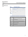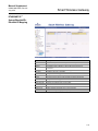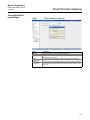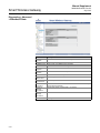
1
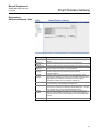
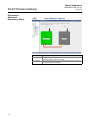
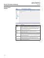
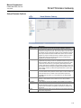
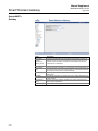
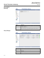
Manual Supplement
00809-0600-4420, Rev AA
July 2012
Smart Wireless Gateway
Smart Wireless Gateway User Interface
Terminology Guide
This document describes the terms, user fields, and parameters used in the
Smart Wireless Gateway Web Based User Interface.
TABLE OF CONTENTS
Home Page . . . . . . . . . . . . . . . . . . . . . . . . . . . . . . . . . . . . . page 1-1
Diagnostics . . . . . . . . . . . . . . . . . . . . . . . . . . . . . . . . . . . . . page 1-2
Explorer . . . . . . . . . . . . . . . . . . . . . . . . . . . . . . . . . . . . . . . . page 1-17
Setup . . . . . . . . . . . . . . . . . . . . . . . . . . . . . . . . . . . . . . . . . . page 1-18
Modbus . . . . . . . . . . . . . . . . . . . . . . . . . . . . . . . . . . . . . page 1-43
OPC . . . . . . . . . . . . . . . . . . . . . . . . . . . . . . . . . . . . . . . . page 1-47
Ethernet/IP™ . . . . . . . . . . . . . . . . . . . . . . . . . . . . . . . . . page 1-49
NOTE
To quickly find any content or term press ctrl+F.
HOME PAGE
Terms
Description
Diagnostics
Monitor
Explorer
Setup
View status of communications, client server parameters, and more.
User created screens for viewing data from field devices.
Basic view of values from field devices.
Configure the Gateway for operation, security and host system integration.
Manual Supplement
00809-0600-4420, Rev AA
July 2012
Smart Wireless Gateway
DIAGNOSTICS
Diagnostics>
Network>Overview
Terms
Description
Active
Advertising
Shows whether active advertising is activated or deactivated. Active
advertising causes the WirelessHART network to send wireless messages
looking for new or unreachable devices to join the network. Active
advertising is automatically activated for 60 minutes when the Gateway is
first powered up, a device becomes unreachable, or no devices are found.
Clicking on setup will navigate to the network speed page in the web based
user interface.
Shows whether fast pipe is activated or deactivated. Fast pipe creates a
dedicated channel for communication to the selected device. Used for large
data transfers (valve signatures, meter verifications, etc…).
Total number of expected field devices.
Fast Pipe
Wireless Device
Count
Live
Stale
Unreachable
Unknown
Wired HART
Device Count
Devices With
Service Denied
Devices That
Need Neighbors
Devices With
Critical Power
Failure
S-2
Number of field devices that are currently communicating on the
WirelessHART network.
Number of field devices that have missed several consecutive updates, but
are not yet classified as unreachable. When a device is classified as stale,
point data for Modbus and OPC is given a bad status.
Number of field devices that have not communicated for 10 minutes or more.
(also considered offline) When a device is classified as unreachable, point
data for Modbus and OPC is given a bad status.
Number of field devices with an unknown state (i.e. not live, late, stale,
etc…).
Number of wired HART field devices that are communicating via a
WirelessHART adapter.
Number of field devices that have been denied bandwidth because a) too
many devices are on the WirelessHART network or b) the device has asked
for an update rate not currently supported by the Gateway. Clicking on
details will navigate to the network devices page in the web based user
interface.
Number of field devices that require another field device (neighbor) to
ensure more robust or optimal communications.
Number of field devices that have reported low supply voltage alert. These
devices have enough power to communicate but may have stopped
reporting the regular updates.
Manual Supplement
00809-0600-4420, Rev AA
July 2012
Smart Wireless Gateway
Terms
Description
Devices With
Unknown
Names
Devices With
Undefined
Names
Devices With
Duplicated
Names
Devices With
Invalid Names
Devices With
Duplicated Ids
Network At
Device Count
Limit
Network Radio
Interface Lost
Factory Support
Accounts
Enabled
Number of field devices whose HART long tag or HART message is not
currently known (typical during the join process).
Using Common
Join Key
Open
Unsecured Port
Device Join
Failure
Device Invalid
MIC
System Up
Time
Number of field devices whose HART long tag or message has been left
blank.
Number of field devices with duplicate HART long tag or HART message.
Number of field devices whose HART long tag or HART message begin with
a ‘-‘ or contains either a ‘.’ or ‘,’.
Number of field devices with duplicate device ids. This should rarely appear
because all devices require unique device ids.
Indicates if the maximum number of devices (100) has been reached. This
field only appears in the web based user interface if true.
Indicates if the Gateway has lost communications to the radio. This field only
appears in the web based user interface if true.
Indicates whether manufacturing and engineering default accounts are
enabled. These accounts are used to program factory settings, model
number, serial number, optional functionality. Also need to be enabled to
perform Gateway firmware updates. This field only appears in the web
based user interface if true.
Indicates whether any field devices are using the common join key when in
access control list mode. This field only appears in the web based user
interface if true.
Indicates whether any unsecure communication ports (non-SSL enabled
Ethernet) are enabled on the security protocols page. This field only appears
in the web based user interface if true.
Indicates whether a field device has requested to join the WirelessHART
network and failed (typically due to security reasons, wrong join key, not on
access control list, etc…). This field only appears in the web based user
interface if true.
Indicates whether a field device has an invalid message integrity check. This
field only appears in the web based user interface if true.
The total time the system has been operational without an interruption
(power-cycle, failure, etc…does not include application restarts).
S-3
Manual Supplement
00809-0600-4420, Rev AA
July 2012
Smart Wireless Gateway
Diagnostics>
Network>Devices
Terms
Description
Hart Tag
32 character HART long tag (or 32 character HART message for wired
HART 5 devices).
The state of the device: live, late, stale, joining, unreachable, or unknown.
Green = live, Red = stale, joining, unreachable, or unknown. Hover over
the node state icon for a more descriptive message.
HART Tag of other field devices with connections to this field device.
Number of other field devices with connections to this field device.
Indicates whether the field device has been denied bandwidth because a)
too many devices are on the WirelessHART network or b) the device has
asked for an update rate not currently supported by the Gateway.
Total number of updates that have not been received by the Gateway.
A…x…C…D… (x indicates a missed update where B should have been).
This is a life time statistic that must be reset manually or via a Gateway
restart.
Percentage of expected data packets that have been received by the
Gateway. 100.0% reliability means that every expected data packet was
received. This number is rounded to the nearest 1/10th percent. This is a
life time statistic that must be reset manual or via a Gateway restart.
Percentage of transmitted packets that have successfully reached their
destination over a given path. Maximum for the field device and its
strongest neighbor.
Neighbor A path stability = 100, Neighbor B path stability = 90, Path
Stability = 100. Calculated in 15 minute cycles.
Maximum received signal strength indication (dBm) for the field device and
its strongest neighbor.
Neighbor A RSSI = -35 dBm, Neighbor B RSSI = -75 dBM, RSSI = -35
dBM. Calculated in 15 minute cycles.
Number of times the field device has joined the network since the last
system reset.
Time that the field device made its last successful join.
Node State
Active Neighbors
Neighbors
Service Denied
Missed Updates
Reliability
Path Stability
Rssi
Joins
Join Time
S-4
Manual Supplement
00809-0600-4420, Rev AA
July 2012
Smart Wireless Gateway
Diagnostics>
Network>Join failures
Terms
Description
Join Failure
When a field device fails to join the WirelessHART network. Most join
failures are due to security reasons (missing or incorrect join key, not on
access control list, etc…).
Time the field device last attempted to join the WirelessHART network.
Number of failed join attempts for this field device.
Unique device identification number. All WirelessHART devices should
begin with 00-1E-1B. The next 4 digit represent the device type. The last 6
vary from device to device.
HART tag of the field device. Generally unknown if in a join failure state.
Indicates if the Device ID appears in the access control list (only when in
access control mode).
Indicates if the field device is communicating with the WirelessHART
network.
Clears all entries for the join failure table.
Navigates to the access control list page in the web based user interface.
Last Failure Time
Failure Count
Device ID
Name
In Access Control
List
Online
Reset List
Edit Access
Control List
S-5
Manual Supplement
00809-0600-4420, Rev AA
July 2012
Smart Wireless Gateway
Diagnostics>
Network>Invalid MICs
S-6
Terms
Description
Message Integrity
Check
Invalid MIC
Diagnostic in each data packet that allows the Gateway to verify the packet
source and contents.
Packet received from field device is not valid. May indicate a security
problem.
Manual Supplement
00809-0600-4420, Rev AA
July 2012
Smart Wireless Gateway
Diagnostics>
Advanced>Network Stats
Terms
Description
Tx Requests
Number of HART messages sent / transmitted by the radio to the field
devices.
Number of time there was no response from the field devices.
Tx Request
Timeouts
Rx Response
Messages
Rx Burst
Messages
Requests
Received
Responses Sent
Average Latency
Average
Reliability
Reset Counts
Number of HART message responses received by the radio from the field
devices. Equal to Tx requests – Tx request timeouts.
Number of burst/published messages received from the field devices.
These messages that are pushed from the device and not
requested/polled for.
Number of HART messages requested by a user application. These
messages are forwarded to the radio to be transmitted. Examples of user
applications are the Gateway’s web based user interface, asset
management software, device configuration software, etc…
Number of HART message responses received from field devices that are
then forwarded on to the requesting user application.
Time difference between when a message is time stamped in a field device
and when it is received by the Gateway’s WirelessHART radio. This value
is the average latency for the entire WirelessHART network.
Percentage of expected data packets that have been received by the
Gateway. 100% reliability means that every expected data packet was
received. This value is the average reliability for the entire WirelessHART
network.
Resets all values for this table. (does not include latency or reliability)
S-7
Manual Supplement
00809-0600-4420, Rev AA
July 2012
Smart Wireless Gateway
Diagnostics>
Advanced>
Redundancy Status
Terms
Description
Active
This gateway is currently in communication with the user. The final
assembly number is shown in the middle.
The redundant gateway must be configured in the redundancy mode and
have the firmware option enabled.
Not Configured
S-8
Manual Supplement
00809-0600-4420, Rev AA
July 2012
Smart Wireless Gateway
Diagnostics>
Advanced>
Redundancy Status
Terms
Description
Switchover
Use this button to switch from the primary gateway to the secondary
gateway. Commonly used to switch out gateways without loss of network.
Now shown with the standby assembly number.
Standby
S-9
Manual Supplement
00809-0600-4420, Rev AA
July 2012
Smart Wireless Gateway
Diagnostics>
Advanced>HART
Stats>XML Stats
Terms
Description
Hart Xml
Refers to HART communications over XML protocol. This is associated
with the AMS Wireless Configurator and AMS Secure communication
protocols.
Number of messages the Gateway has received from a client application
(this is typically AMS Wireless Configurator).
Number of messages the Gateway has returned to a client application (this
is typically AMS Wireless Configurator).
Number of periodic (scheduled) messages the Gateway has received from
a client application. This is typical when AMS Wireless Configurator has
been setup to poll for device alerts using the Alert Monitor application.
Number of messages the Gateway has forwarded to field devices. Not all
messages received are forwarded because some information is cached in
the Gateway.
Number of messages the Gateway has received from field devices in
response to forwarded requests.
Number of total connections from client applications accepted over time
(not the current number of connections).
Resets all values for this table.
Messages
Received
Messages
Returned
Messages
Broadcast
Requests
Forwarded
Responses
Returned
Accepted
Connections
Reset Counts
S-10
Manual Supplement
00809-0600-4420, Rev AA
July 2012
Smart Wireless Gateway
Diagnostics>
Advanced>HART
Stats>UDP Stats
Terms
Description
Hart Udp
Refers to HART communications over UPD protocol. This is associated
with the HART UDP Port communication protocol.
Number of messages the Gateway has received from a client application
(this is typically AMS Wireless Configurator).
Number of messages the Gateway has returned to a client application (this
is typically AMS Wireless Configurator).
Number of periodic (scheduled) messages the Gateway has received from
a client application. This is typical when AMS Wireless Configurator has
been setup to poll for device alerts using the Alert Monitor application.
Number of messages the Gateway has forwarded to field devices. Not all
messages received are forwarded because some information is cached in
the Gateway.
Number of messages the Gateway has received from field devices in
response to forwarded requests.
Number of total connections from client applications accepted over time
(not the current number of connections).
Resets all values for this table.
Messages
Received
Messages
Returned
Messages
Broadcast
Requests
Forwarded
Responses
Returned
Accepted
Connections
Reset Counts
S-11
Manual Supplement
00809-0600-4420, Rev AA
July 2012
Smart Wireless Gateway
Diagnostics>
Advanced>HART
Stats>TCP Stats
Terms
Description
Hart Tcp
Refers to HART communications over TCP protocol. This is associated
with the HART TCP Port and HART TCP Port Secure communication
protocol.
Number of messages the Gateway has received from a client application
(this can be any HART enabled host).
Number of messages the Gateway has returned to a client application (this
can be any HART enabled host).
Number of periodic (scheduled) messages the Gateway has received from
a client application.
Number of messages the Gateway has forwarded to field devices. Not all
messages received are forwarded because some information is cached in
the Gateway.
Number of messages the Gateway has received from field devices in
response to forwarded requests.
Number of total connections from client applications accepted over time
(not the current number of connections).
Resets all values for this table.
Messages
Received
Messages
Returned
Messages
Broadcast
Requests
Forwarded
Responses
Returned
Accepted
Connections
Reset Counts
S-12
Manual Supplement
00809-0600-4420, Rev AA
July 2012
Smart Wireless Gateway
Diagnostics>
Advanced>Modbus
Stats>Serial Stats
Terms
Description
Messages
Receive
Crc Errors
Number of messages received from the Modbus master device.
Messages
Transmit
Error Responses
Reset Counts
Number of cyclic redundancy check errors. Crc errors generally indicate
noise in transmission or problems with data integrity.
Number of response messages transmitted from the Gateway.
Number of error response messages transmitted from the Gateway.
Resets all values for this table.
S-13
Manual Supplement
00809-0600-4420, Rev AA
July 2012
Smart Wireless Gateway
Diagnostics>
Advanced>Modbus
Stats>TCP Stats
S-14
Terms
Description
Messages
Received
Messages
Transmitted
Error Responses
Open
Connections
Accepted
Connections
Reset Counts
Number of messages received from the Modbus TCP device.
Number of response messages transmitted from the Gateway.
Number of error response messages transmitted from the Gateway.
Number of current connections from Modbus TCP masters.
Number of total connections from Modbus TCP masters accepted over
time (not the current number of connections).
Resets all values for this table.
Manual Supplement
00809-0600-4420, Rev AA
July 2012
Smart Wireless Gateway
Diagnostics>
Advanced>System Stats
Terms
Description
Cpu Usage
Central Processing Unit (CPU) utilization (time used by a process) by
application or kernel.
Percentage of CPU utilization that occurred while executing at the user
level (application).
Percentage of CPU utilization that occurred while executing at the system
level (kernel).
Combine Percentage CPU utilization, User + System.
Random Access Memory.
Total memory or disk space.
Portion of memory or disk space that has been used.
Disk space reserved for Gateway operating system, user interface pages
and configuration data.
Disk space reserved for log files, custom pages, and custom trends.
User
System
Total
Ram
Size
Used
Main Filesystem
Temporary
Filesystem
Logs
Disk space taken by diagnostic log files.
S-15
Manual Supplement
00809-0600-4420, Rev AA
July 2012
Smart Wireless Gateway
Diagnostics>
Advanced>
Client/Server
Terms
Description
Server
Client
Hg Version
The WirelessHART Gateway web server application.
PC client that is currently logged onto the Gateway.
WirelessHART Gateway firmware version. Version 3.7.1 is the initial
release version for WirelessHART.
Hostname assigned to the Gateway.
Hardware MAC address for the primary and secondary Ethernet ports.
Gateway serial number (or final assembly number).
Program manager serial number from Dust Networks.
Name
Physical Address
Hg Serial Number
Pm Serial
Number
HG Model
Number
Hg Device Id
Network
Frequency
Hart Universal
Revision
Browser Name
Browser Version
Operating System
Screen Width
Screen Height
Color Depth
User Agent Info
Java Enabled
IP Address
Remote User
S-16
Gateway model number.
Gateway unique identification number.
Radio frequency band that wireless field network operates. Typically this is
2.4 GHz, but 900 MHz was available for pre-WirelessHART networks. All
WirelessHART networks are 2.4 GHz.
The major revision of HART specification that applies to this Gateway.
The web browser application that is currently accessing the Gateway.
The web browser version.
Operating system of the PC client currently accessing the Gateway.
Screen width resolution for the PC client.
Screen height resolution for the PC client.
Number of colors (in millions) used by the PC client to render images.
Information provided by web browser for further identification.
Indicates whether Java script is enabled.
IP address of the PC client.
User role used to log into the Gateway.
Manual Supplement
00809-0600-4420, Rev AA
July 2012
Smart Wireless Gateway
EXPLORER
Terms
Description
Hart Tag
32 character HART long tag (or 32 character HART message for wired
HART 5 devices).
HART status parameter, this is the overall field device status. Hover over
the status icon for a more descriptive message.
Time stamp of the last measurement received by the wireless field device.
Value of the HART primary variable (1st variable).
Value of the HART secondary variable (2nd variable).
Value of the HART tertiary variable (3rd variable).
Value of the HART quaternary variable (4th variable).
Interval in which the field device transmits it’s measurement data to the
Gateway. Some field devices burst multiple messages and at different
rates. For Burst rates under 1 minute this is reported in seconds. For Burst
rates of 1 minute or greater this is reported in hh:mm:ss.
HART Status
Last Update
PV
SV
TV
QV
Burst Rate
S-17
Manual Supplement
00809-0600-4420, Rev AA
July 2012
Smart Wireless Gateway
SETUP
Setup>Network>
Settings
Terms
Description
Network Name
Network ID
User define network name.
Identification number that tells field devices what WirelessHART network it
belongs to.
Selects whether the Gateway uses a common join key or access control
list to determine who can join the WirelessHART network.
Under this security mode, the entire WirelessHART network uses the same
join key in order to join the network.
Under this security mode, the Gateway maintains an access control list
where each device has a separate unique join key.
Allows the user to see the current common join key for the WirelessHART
network.
Causes the Gateway to generate a new common join key. Changes must
be submitted before taking affect and will propagate to all wireless devices
currently joined to the WirelessHART network.
Causes the Gateway to generate a new random network key (encryption)
on a periodic basis.
The period of time in days before the Gateway will generate a new random
network key.
Cause the Gateway to generate a new network key. Changes must be
submitted before taking affect and will propagate to all wireless devices
currently joined to the WirelessHART network.
Accepts all changes (highlighted in yellow).
Security Mode
Common Join
Key
Access Control
List
Show Join Key
Generate
Random Join Key
Rotate Network
Key?
Key Rotation
Period (Days)
Change Network
Key Now?
Submit
S-18
Manual Supplement
00809-0600-4420, Rev AA
July 2012
Smart Wireless Gateway
Setup>Network>
Settings>Access Control
List
Terms
Description
Device ID
Unique device identification number. All WirelessHART devices should
begin with 00-1E-1B. The next 4 digit represent the device type. The last 6
vary from device to device.
The device’s HART Tag
Generates a new unique join key for the device.
Device Name
Generate New
Join Key
Online
Common Join
Key
Default Join Key
<<First
<<Previous
Search
Next>>
Last>>
New Entry
Show Join Failure
Add Entries For
Join Failure
Delete Selected
Check Generate
Key For Selected
Select All
Select None
Select Online
Select New Join
Key
Recommended
Submit
Indicates the device is communicating on the WirelessHART network.
Indicates the device is using a common join key.
Indicates the device is using the default join key.
Navigates to the first page of this table.
Navigates to the previous page of this table.
Finds the next occurrence of the characters entered into this field.
Navigates to the next page of this table.
Navigates to the last page of this table.
Creates a new entry in this table.
Navigates to the join failures page in the web interface.
Creates new entries in this table and populates them with the current join
failures.
Removes the selected entry from this table.
Checks the Generate New Join Key box for all selected entries.
Selects all table entries.
Deselects all table entries.
Selects all online devices in this table.
Selects all devices with a common join key or a default join key.
Accepts all changes (highlighted in yellow).
S-19
Manual Supplement
00809-0600-4420, Rev AA
July 2012
Smart Wireless Gateway
Setup>Network>
Speed
Terms
Description
Active Advertising
Shows whether active advertising is activated or deactivated. Active
advertising causes the WirelessHART network to send wireless messages
looking for new devices to join the network. Active advertising is
automatically activated for 30 minutes when the Gateway is powered up.
Determines how long (in minutes) active advertising will be enabled.
Duration
(Minutes)
Activate
Fast Pipe
Inactivity Timeout
(Minutes)
Device Selector
Activate
S-20
Causes the WirelessHART network to enter active advertising mode
Shows whether fast pipe is activated or deactivated. Fast pipe creates a
dedicated channel for communication to the selected device. Used for
large data transfers. (valve signatures, meter verifications, etc…)
Determines how long (in minutes) Fast pipe will remain active when no
polled requests are being sent (or idle connection) to the field device.
Selects a device to establish fast pipe.
Establish a fast pipe connection with the selected field device.
Manual Supplement
00809-0600-4420, Rev AA
July 2012
Smart Wireless Gateway
Setup>Network>
Bandwidth
Terms
Description
Analyze Again
Analyzes the WirelessHART network to determine if any devices require
more bandwidth.
Changes Gateway network bandwidth settings. This option only appears if
a change is required for a device to communicate or if change will help
optimize the network. Note that this will temporarily reset the network.
Update
S-21
Manual Supplement
00809-0600-4420, Rev AA
July 2012
Smart Wireless Gateway
Setup>Network>
Redundancy
S-22
Terms
Description
Redundant Mode
First Node
Second Node
Primary Node
Use to place the gateway in redundant mode from simplex
Determine the name of the primary gateway
Determine the name of the secondary gateway
Use to make the primary graphic on the left or right
Manual Supplement
00809-0600-4420, Rev AA
July 2012
Smart Wireless Gateway
Setup>Ethernet Protocol
Terms
Description
Primary Interface
Refers to Ethernet port 1. (optional may refer to fiber optic port if fiber optic
is enabled)
Refers to Ethernet port 2. (optional may refer to Ethernet port 1 if fiber optic
is enabled)
Causes the associated interface to obtain an IP address from a DHCP
server.
Secondary
Interface
Obtain An IP
Address From A
DHCP Server
Obtain Domain
Name From
DHCP Server
Specify An IP
Address
Hostname
Domain Name
IP Address
Netmask
Gateway
Submit
Causes the associated interface to obtain a Domain Name from a DHCP
server.
Causes the associated interface to use a specific IP address.
Hostname for the WirelessHART Gateway.
Name of the Domain that the WirelessHART Gateway will join.
User specified IP address for the associated interface.
User specified netmask for the associated interface.
User specified gateway for the associated interface. (not to be confused
with the WirelessHART Gateway).
Accepts all changes (highlighted in yellow).
S-23
Manual Supplement
00809-0600-4420, Rev AA
July 2012
Smart Wireless Gateway
Setup>Security>
User Accounts
S-24
Terms
Description
New
Administrator
Password
New Maintenance
Password
New Operator
Password
New Executive
Password
Confirm
Enable Factory
Support Accounts
Submit
Field for entering a new administrator password.
Field for entering a new maintenance password.
Field for entering a new operator password.
Field for entering a new executive password.
Field to confirm the new password for each user role.
Allows factory support personnel to log onto the Gateway and change
factory settings.
Accepts all changes (highlighted in yellow).
Manual Supplement
00809-0600-4420, Rev AA
July 2012
Smart Wireless Gateway
Setup>Security>
Certificates
Terms
Description
Import GW
Certificate Into
Webrowser
Rebuild GW
Certificates
Sends Gateway security certificates to the current web browser.
Rebuilds the security certificates for the Gateway. This process may take
time and interrupt Gateway communications.
S-25
Manual Supplement
00809-0600-4420, Rev AA
July 2012
Smart Wireless Gateway
Setup>Security>
User Options
Terms
Description
Minimum length
Lowercase count
Minimum number of characters required to establish a new password.
Minimum number of lower case characters required to establish a new
password.
Minimum number of upper case characters required to establish a new
password.
How many total characters required to establish a new password.
Number of complex characters required in each password.
Minimum idle time allowed on the browser.
Uppercase count
Digit count
Symbol count
Session idle
timeout
Maximum session
lifetime
Minimum
password lifetime
Maximum
password lifetime
Password failure
limit
Password failure
lock
Password failure
wait
Password history
depth
S-26
Maximum amount of time one session can be available without
authentication.
Minimum amount of time one password can remain with one user.
Maximum amount of time one password can remain with one user.
Amount of times an incorrect password can be submitted before the user is
locked from the gateway.
Used to turn on this feature.
Amount of time the user must wait until the admin account is unlocked after
a failure lockout.
Number of previous passwords that can not be used again.
Manual Supplement
00809-0600-4420, Rev AA
July 2012
Smart Wireless Gateway
Setup>Security>
Access List
Terms
Description
Organization
Common Name
Email
Expires
<<First
<<Previous
Search
Next>>
Last>>
Delete selected
Select All
Select None
Select Errors
The client’s organization.
The client’s name (PC name).
The client’s email address.
Date when client certificate is no longer valid.
Navigates to the first page of this table.
Navigates to the previous page of this table.
Finds the next occurrence of the characters entered into this field.
Navigates to the next page of this table.
Navigates to the last page of this table.
Removes the selected entry from this table.
Selects all table entries.
Deselects all table entries.
Selects all table entries with error messages.
S-27
Manual Supplement
00809-0600-4420, Rev AA
July 2012
Smart Wireless Gateway
Setup>Security>
Protocol
Terms
Description
Enable
Enables associated communication protocol and opens the specified TCP
/ UDP port.
Type of Ethernet communication protocol.
The TCP port used by the associated communication protocol.
The UDP port used by the associated communication protocol.
Ethernet communication protocol used to talk to asset management hosts.
Protocol
TCP Port
UDP Port
AMS Wireless
Configurator
AMS Secure
HART Port
HART Port
Secure
HTTP
HTTPS
Modbus TCP
Modbus TCP
Secure
NTP
OPC Comm
OPC Comm
Secure
Submit
Defaults
S-28
SSL enabled Ethernet communication protocol used to talk to asset
management hosts. Also requires HTTPS.
Ethernet communication protocol used to talk to HART enabled hosts.
SSL enabled Ethernet communication protocol used to talk to HART
enabled hosts. Also requires HTTPS.
Ethernet communication protocol used for the Gateway's web based user
interface.
SSL enabled Ethernet communication protocol used for the Gateways web
based user interface.
Ethernet communication protocol used to talk to Modbus TCP enabled
hosts.
SSL enabled Ethernet communication protocol used to talk to Modbus
TCP enabled hosts. Also requires HTTPS.
Communication port used to talk to a Network Time Protocol (NTP) server
Ethernet communication protocol used to talk to the Gateway OPC proxy
server.
SSL enabled Ethernet communication protocol used to talk to the Gateway
OPC proxy server. Also requires HTTPS.
Accepts all changes (highlighted in yellow).
Restores the default protocols and port numbers.
Manual Supplement
00809-0600-4420, Rev AA
July 2012
Smart Wireless Gateway
Setup>Log Settings
Terms
Description
Remote Server IP
Address
Remote Server
Port
Syslog Protocol
The IP address of the machine running the remote Syslog server
Syslog Transport
Require Trusted
Server
Certificate?
Log keep-alive
message?
Keep-alive
message
frequency
The protocol port that the remote Syslog server is using
Syslog uses two common formats for logged messages. The newer format
is referred to as IETF-Syslog and is defined in RFC 5424. The legacy
format is referred to as BSD and is defined in RFC 3164.
The transport used for communication with the remote Syslog server.
Choices are UDP, TCP or TLS (which is encrypted).
When using TLS encrypted communication, the remote Syslog server can
use a trusted certificate or can use a certificate unknown to the 1420.
Select ‘Yes’ for an added level of security and exchange keys with the
1420 using the Security Setup on remote Syslog server.
A ‘keep-alive’ message can be sent by the 1420 when no other log activity
has occurred. This provides another means for the remote Syslog server to
verify communication with the 1420.
The frequency the ‘keep-alive’ message is sent when no other log activity
has occurred.
S-29
Manual Supplement
00809-0600-4420, Rev AA
July 2012
Smart Wireless Gateway
Setup>Time
Terms
Description
Your PC’s Time
GW Time
Difference
Method Used To
Set Time
Network Time
Protocol (Ntp)
Set With PC Time
The time used by the PC client.
The time currently used by the Gateway.
The difference between the PC client time and the Gateway time.
Selected what method to use when setting the Gateway time.
Manual Entry
Date (Mm/Dd/Yy)
Time (Hh:Mm:Ss)
Submit
S-30
Uses an NTP time server to regulate the Gateway time. Will also require
an IP address and packet version of the NTP time server.
Uses the current PC client time to set the Gateway time. This will reset the
WirelessHART network.
Uses the Date and Time fields to set the Gateway time. This will reset the
WirelessHART network.
Manually enter the date (mm/dd/yy)
Manually enter the time (hh:mm:ss)
Accepts all changes (highlighted in yellow).
Manual Supplement
00809-0600-4420, Rev AA
July 2012
Smart Wireless Gateway
Setup>System
Backup>Save
Terms
Description
Include diagnostic
information in
system backup
Save
Configuration
Saves Gateway diagnostic log information with the system backup file.
Collects the Gateway configuration data and creates a system backup file.
This system backup file is saved on the PC client as a zip file (*.zip).
System backups contain user passwords as well as keys used for
encrypting communications. Be sure to store downloaded system backups
in a secure location.
S-31
Manual Supplement
00809-0600-4420, Rev AA
July 2012
Smart Wireless Gateway
Setup>System
Backup>Restore
Terms
Description
Browse…
Opens a navigation window to locate a system backup file (zip file) on the
PC client.
Restores the select backup file to the Gateway.
Upload
Configuration
Reset Defaults
S-32
Returns the Gateway to default factory configuration.
Manual Supplement
00809-0600-4420, Rev AA
July 2012
Smart Wireless Gateway
Setup>Page
Options>Point Pages
Terms
Description
Name
Order
Name of the custom point page (user specified).
The order in which custom point pages appear in the Monitor section of the
navigation menu.
Moves the associated point page up in the navigation order.
Moves the associated point page down in the navigation order.
The actions you can perform on the associated point page.
Navigates to the configuration of the associated page and allows the user
to make changes.
Deletes the associated page.
Navigates to the associated point page in the web interface.
Starts a new custom point page.
Accepts all changes (highlighted in yellow).
UP
Down
Actions
Edit
Delete
Go to
New
Submit
S-33
Manual Supplement
00809-0600-4420, Rev AA
July 2012
Smart Wireless Gateway
Setup>Page
Options>Point
Pages>Editing Custom
Page
Terms
Description
Page Name
The name of this custom point page as it will appear in the navigation
menu.
Identifies the data point to display. Point Names appear in the format
HARTtag.parameter
User specified name for the data point.
User specified description for the data point.
The order in which the associated data point appears on the custom point
page.
Moves the associated data point up in the order.
Moves the associated data point down in the order.
Navigates to the first page of this table.
Navigates to the previous page of this table.
Finds the next occurrence of the characters entered into this field.
Navigates to the next page of this table.
Navigates to the last page of this table.
Removes the selected entry from this table.
Selects all table entries.
Deselects all table entries.
Selects all table entries with error messages.
Accepts all changes (highlighted in yellow).
Point Name
Name
Description
Order
Up
Down
<<First
<<Previous
Search
Next>>
Last>>
Delete selected
Select All
Select None
Select Errors
Submit
S-34
Manual Supplement
00809-0600-4420, Rev AA
July 2012
Smart Wireless Gateway
Setup>Page
Options>Point Columns
Terms
Description
Device
Indicates if the Device column appears as default in the monitoring point
pages.
Indicates if the Device Desc column appears as default in the monitoring
point pages.
Indicates if the Parameter column appears as default in the monitoring
point pages.
Indicates if the Point column appears as default in the monitoring point
pages.
Indicates if the Name column appears as default in the monitoring custom
point pages.
Indicates if the Description column appears as default in the monitoring
custom point pages.
Indicates if the Value column appears as default in the monitoring point
pages.
Indicates if the Units column appears as default in the monitoring point
pages.
Indicates if the Status Description column appears as default in the
monitoring point pages.
Indicates if the Status Icon column appears as default in the monitoring
point pages.
Accepts all changes (highlighted in yellow).
Device Desc
Parameter
Point
Name
Description
Value
Units
Status Description
Status Icon
Submit
S-35
Manual Supplement
00809-0600-4420, Rev AA
July 2012
Smart Wireless Gateway
Setup>Page
Options>Home Pages
Terms
Description
GW menu
overview
Custom Page
Indicates that the Gateway menu overview is the default home page when
logging into the Gateway web based user interface.
Indicates that the Custom Point Page is the default home page when
logging into the Gateway web based user interface.
Indicates that the Point Monitor Page is the default home page when
logging into the Gateway web based user interface.
Indicates that the HART Status Page is the default home page when
logging into the Gateway web based user interface.
Indicates that the Quick Point Data page is the default home page when
logging into the Gateway web based user interface.
Indicates that the Network Status page is the default home page when
logging into the Gateway web based user interface.
Accepts all changes (highlighted in yellow).
Point monitor
HART Status
Quick Point Data
Network Status
Submit
S-36
Manual Supplement
00809-0600-4420, Rev AA
July 2012
Smart Wireless Gateway
Setup>Restart Apps
Terms
Description
Application
software
Suspend
Gateway
Operations
Restart
Software for the web user interface, program manager, operating system,
etc…
The Gateway will temporarily be inaccessible via the web based user
interface. It will stop reporting Modbus or OPC values or collecting trend
data.
Software reset similar to restarting a PC. This is required for some
configuration changes to take affect. A physical power cycle may erase
configuration changes before they take affect.
Begins the restart process.
Delays the restart process, configuration changes will be stored in buffer.
Yes
No
S-37
Manual Supplement
00809-0600-4420, Rev AA
July 2012
Smart Wireless Gateway
Setup>Firmware
Upgrade
Terms
Description
Firmware
Upgrade
Firmware (sometimes called software) Upgrade; this is a procedure for
installing newer/improved firmware in the gateway. This should only be
done by recommendation of your Emerson Representative. Please note: A
firmware upgrade will require a restart (shut down of wireless system) be
sure to carefully follow the recommended upgrade procedure that is
supplied with the firmware upgrade.
A firmware (sometimes called software) release by Emerson that is
recommended for upgrading the gateway with new features or
improvements in operation
A zip file is a file that ends with the extension .zip, this is a compressed file
to reduce its size and make it easier to share. Please note: When receiving
and saving this file before upgrading do not use any program with offers to
decompress or expand the zip file. The gateway will expand the zip file
automatically while upgrading.
To manually look for and find the upgrade zip file. After receiving a
firmware upgrade from Emerson save the zip file in a location that is
accessible by the gateway. Use Browse to locate this file and select it.
Begins the Firmware upgrade process after the proper Firmware upgrade
zip file was located using Browse.
Firmware
Release
Zip File
Browse
Upgrade
S-38
Manual Supplement
00809-0600-4420, Rev AA
July 2012
Smart Wireless Gateway
Setup>Firmware Options
Terms
Description
Firmware Options
Firmware Options are items that are normally installed by the factory;
these options are called out in the initial factory order and are normally not
needed to be changed in the field. This Firmware Options process allows
the gateway user to reconfigure the gateway for use with different systems,
which may be added in the field at a later date. Please note: A firmware
upgrade may require a restart (shut down of wireless system) be sure to
carefully follow the recommended firmware options procedure that is
supplied with the firmware option’s file.
A file with the extension .txt that has been supplied by your Emerson
representative specifically to make an operational interface change for this
particular gateway. Option files are issued for specific gateways by serial
number and can be used only by the gateway with that specific serial
number. Option files are reusable in the appropriate gateway. Please note:
The Firmware option file changes the gateway’s factory defaults to the new
option settings. Contact your Emerson representative for an option file if
one is needed.
Shows gateway interface options that are currently installed. A check mark
in the box indicates that a particular interface option has been installed. No
check indicates it has not. Please note: Not all interface options are
compatible with one another; so if some boxes are not checked that is
appropriate.
These are various interfaces that can be used to communicate with the
gateway. A short definition of the interface is in the column labeled
“Description.”
A short definition of each user interface option available in the gateway.
To manually look for and find the firmware option file (.txt). After receiving a
firmware upgrade from Emerson save the zip file (do not unzip it) in a
location that is accessible by the gateway. Use Browse to locate this file
and select it.
Begins the Firmware option process after the proper firmware options file
was located using Browse.
Gateway Option
Installed
Option
Description
Browse
Submit
S-39
Manual Supplement
00809-0600-4420, Rev AA
July 2012
Smart Wireless Gateway
Setup>HART>
Gateway
Terms
Description
Use internet
protocol
hostname for
gateway name
Gateway Name
HART Master
Type
Uses the hostname field under the Internet protocol page to replace the
Gateway name. This is a one time action that happens when the box is
checked. Further hostname changes will not be reflected on this page
unless the box is rechecked.
HART Tag for the Gateway.
Indicates whether the Gateway is communicating as the HART primary or
secondary master. Most host systems operate as a secondary master and
leave primary master status to a handheld device.
The Gateway will have priority status when issuing commands to wireless
field devices.
The Gateway will yield to commands given to the wireless field device by a
primary master.
Number of times the Gateway will attempt to resend a message when it
does not get a confirmation.
Accepts all changes (highlighted in yellow).
Primary
Secondary
Network Retry
Count
Submit
S-40
Manual Supplement
00809-0600-4420, Rev AA
July 2012
Smart Wireless Gateway
Setup>HART>Device
Terms
Description
Device ID
Unique device identification number. All WirelessHART devices should
begin with 00-1E-1B. The next 4 digits represent the device type. The last
6 vary from device to device.
Configures the HART long tag (32 characters) or HART message (32
characters, only used for HART 5 wired devices connected via a
WirelessHART adapter)
Configures the HART tag (8 characters). Typically used for short displays
like a local LCD.
Configures descriptive message. (16 characters).
Configures the engineering units of measure.
Configures the interval in which the wireless field devices transmit
measurement data to the Gateway.
Removes the wireless field device from the WirelessHART network.
Percentage of user defined range associated with the HART primary
variable.
Configure the lower range limit and upper range limit.
Navigates to the first page of this table.
Navigates to the previous page of this table.
Finds the next occurrence of the characters entered into this field.
Navigates to the next page of this table.
Navigates to the last page of this table.
Accepts all changes (highlighted in yellow).
HART Tag
Short Tag
Descriptor
Units
Burst Rate
Delete
% Range
Edit
<<First
<<Previous
Search
Next>>
Last>>
Submit
S-41
Manual Supplement
00809-0600-4420, Rev AA
July 2012
Smart Wireless Gateway
Setup>HART>
Hierarchy
Terms
Description
Include Gateways
Enables the Gateway to be seen as a field device on device specific pages
(monitor, explorer, etc…)
Enables WirelessHART adapters (Smart Wireless THUM adapter) to be
seen as a field device on device specific pages (monitor, explorer, etc…)
Accepts all changes (highlighted in yellow).
Include Adapters
Submit
Setup>Changes
S-42
Terms
Description
Description
From
To
Requested
Status
Provides a description of what changes have been submitted.
Initial value.
Final value.
Timed the change was submitted.
Indicates if the change has been successful, is in process, or has failed.
Manual Supplement
00809-0600-4420, Rev AA
July 2012
Smart Wireless Gateway
MODBUS
Setup>Modbus>
Communication
Terms
Description
One Modbus
Address
Multiple Modbus
Addresses
Modbus TCP Port
Selects a single Modbus RTU slave address to be used.
Baud Rate
Parity
Stop Bits
Response delay
time (ms)
Unmapped
register read
response?
Unmapped
register write
response?
Floating Point
Representation
Float
Round
Scale
Use swapped
floating point
format?
Incorporate
value’s
associated status
as error?
Allows multiple Modbus RTU slave address to be used. These addresses
are configured per point in the Modbus mapping page.
The TCP Port used to access Modbus TCP data directly from the Gateway.
Note this is a different port than the SSL enabled Modbus TCP data.
Communication speed for Modbus RTU.
Selects whether parity is used for Modbus RTU messages and whether it is
even or odd.
Sets the number of stop bits for Modbus RTU messages.
After receiving a request, the Gateway will wait this long before it sends a
response.
The response the Gateway sends if no point data is mapped to the register
during a read request. The Gateway can either return zero for the
requested register or Illegal data addr.
The response the Gateway sends if no point data is mapped to the register
during a write request. The Gateway can either return OK for the write
request or Illegal data addr.
The format that Modbus data is given.
Floating point number that is given over two 16 bit Modbus registers.
Rounded integer that is given over one 16 bit Modbus register. If the
measured value = 2711.97, the rounded value = 2712.
Scaled integer that is given over one 16 bit Modbus register. The Gateway
uses the equation y=Ax-(B-32768). y = scaled integer returned by the
Gateway, A = gain, x = measured value, B = offset.
Reverses which significant register used in a floating point representation.
If the HART variable status indicates a critical failure or if there is a loss of
communications, it will be reported through the Modbus register.
S-43
Manual Supplement
00809-0600-4420, Rev AA
July 2012
Smart Wireless Gateway
Terms
Description
Value reported for
error (floating
point)
NaN
Chooses what value is reported if the value’s associated status indicates a
critical failure. Only used if the Gateway is using float representation.
+Inf
-Inf
Other
Not a number is reported if the value’s associated status indicates a critical
failure.
Positive infinity is reported if the value’s associated status indicates a
critical failure.
Negative infinity is reported if the value’s associated status indicates a
critical failure.
User defined value is reported if the value’s associated status indicates a
critical failure.
User defined value is reported if the value’s associated status indicates a
critical failure. Only used if the Gateway is using rounded or scaled
representation
Highest integer proportional to the measured value. Default = 65534. This
is generally the highest integer value accepted by the host system.
Value reported for
error (rounded or
native integer)
Scaled floating
point maximum
integer value
Use global scale
Determines if scaled integers use the Global scale gain and offset or
gain and offset?
unique gain and offsets for each measured value.
Global Scale Gain Gain used by all measured values for scaled integers. The Gateway uses
the equation y=Ax-(B-32768). y = scaled integer returned by the Gateway,
A = Global scale gain, x = measured value, B = Global scale offset.
Global Scale
Offset used by all measured values for scaled integers. The Gateway uses
Offset
the equation y=Ax-(B-32768). y = scaled integer returned by the Gateway,
A = Global scale gain, x = measured value, B = Global scale offset.
S-44
Manual Supplement
00809-0600-4420, Rev AA
July 2012
Smart Wireless Gateway
Setup>Modbus>
Mapping
Terms
Description
Show / Hide
System Registers
Shows/Hides predefined system registers. 49001 = current year, 49002 =
current month, 49003 = current day, 49004 = current hour, 49005 = current
minute, 49006 = current second, 490007 = messages received
Modbus RTU slave address. Only used if multiple Modbus addresses is
selected on the Modbus Communication page.
Memory location used to reference point data via Modbus protocol.
Modbus holding register.
Assigned data point in the format HARTtag.parameter.
For Booleans, indicates which value will be reported as a 1. For integers,
identifies a particular bit to be reported as a 1. Reserved for registers less
than 20000.
Switches the 0 or 1 response for discrete state values.
Unique register gain used for scaled integer format. Not used if global
scale gain and offset is selected on the Modbus Communication page.
Unique register offset used for scaled integer format. Not used if use global
scale gain and offset is selected on the Modbus Communication page.
Navigates to the first page of this table.
Navigates to the previous page of this table.
Finds the next occurrence of the characters entered into this field.
Navigates to the next page of this table.
Navigates to the last page of this table.
Creates a new entry in this table.
Removes the selected entry from this table.
Selects all table entries.
Deselects all table entries.
Selects all table entries that have an error message.
Accepts all changes (highlighted in yellow).
Address
Register
Point Name
State
Invert
Gain
Offset
<<First
<<Previous
Search
Next>>
Last>>
New Entry
Delete Selected
Select All
Select None
Select Errors
Submit
S-45
Manual Supplement
00809-0600-4420, Rev AA
July 2012
Smart Wireless Gateway
Setup>Modbus>
Import/Export
Terms
Description
CSV file
Browse…
Comma delimited or comma separated file format.
Opens a navigation window to locate a Modbus mapping backup file (CSV
file) on the PC client.
Restores the selected Modbus mapping backup file to the Gateway.
Upload
Configuration
Download
Configuration
S-46
Collects the Gateway Modbus mapping data and creates a backup file.
This Modbus mapping backup file is saved on the PC client as a CSV file
(*.csv).
Manual Supplement
00809-0600-4420, Rev AA
July 2012
Smart Wireless Gateway
OPC
Setup>OPC>Browse
Tree
Terms
Description
Add all PV
Inserts a new table entry for the primary value of every wireless field
device.
Assigned data point in the format HARTtag.parameter.
Cause point data to be represented in a string of characters rather than the
default 32 bit floating point.
Navigates to the first page of this table.
Navigates to the previous page of this table.
Finds the next occurrence of the characters entered into this field.
Navigates to the next page of this table.
Navigates to the last page of this table.
Creates a new entry in this table.
Removes the selected entry from this table.
Selects all table entries.
Deselects all table entries.
Selects all table entries that have an error message.
Accepts all changes (highlighted in yellow).
Point Name
String Value
<<First
<< Previous
Search
Next>>
Last>>
New entry
Delete selected
Select All
Select None
Select Errors
Submit
S-47
Manual Supplement
00809-0600-4420, Rev AA
July 2012
Smart Wireless Gateway
Setup>OPC>
Import/Export
Terms
Description
CSV file
Browse…
Comma delimited or comma separated file format.
Opens a navigation window to locate an OPC browse tree backup file
(CSV file) on the PC client.
Restores the select OPC browse tree backup file to the Gateway.
Upload
Configuration
Download
Configuration
S-48
Collects the Gateway OPC browse tree data and creates a backup file.
This OPC browse tree backup file is saved on the PC client as a CSV file
(*.csv).
Manual Supplement
00809-0600-4420, Rev AA
July 2012
Smart Wireless Gateway
ETHERNET/IP™
Setup>EtherNet/IP>
EtherNet/IP Mapping
Terms
Description
Input Instance
Output Instance
Member
EtherNet/IP Input Static Assembly Instance - 496 bytes.
EtherNet/IP Output Static Assembly Instance - 496 bytes.
EtherNet/IP Instance Member in which data will get produced or
consumed.
Assigned data point in the format HARTtag.parameter.
Creates a new entry in this table.
Navigates to the first page of this table.
Navigates to the previous page of this table
Finds the next occurrence of the characters entered into this field.
Navigates to the next page of this table.
Navigates to the last page of this table.
Removes the selected entry from this table.
Selects all table entries.
Deselects all table entries.
Selects all table entries that have an error message.
Accepts all changes (highlighted in yellow).
Point Name
New entry
<<First
<<Previous
Search
Next>>
Last>>
Delete Selected
Select All
Select None
Select Errors
Submit
S-49
Manual Supplement
00809-0600-4420, Rev AA
July 2012
Smart Wireless Gateway
Setup>EtherNet/IP>
EtherNet/IP
Communication
Terms
Description
Assembly Object
Type
EtherNet/IP TCP
Port
EtherNet/IP UDP
Ports
Incorporate
value’s
associated status
as error?
Value reported for
error (floating
point)
NaN
EtherNet/IP use Static assembly object.
+Inf
-Inf
Other
Value reported for
error (native
integer)
S-50
The TCP Port used to access EtherNet/IP TCP data directly from the
Gateway.
The UDP Ports used to access EtherNet/IP UDP data directly from the
Gateway.
If the HART variable status indicates a critical failure or if there is a loss of
communications, it will be reported through the EtherNet/IP member.
Chooses what value is reported if the value’s associated status indicates a
critical failure. Only used if the Gateway is using float representation
Not a number is reported if the value’s associated status indicates a critical
failure.
Positive infinity is reported if the value’s associated status indicates a
critical failure.
Negative infinity is reported if the value’s associated status indicates a
critical failure.
User defined value is reported if the value’s associated status indicates a
critical failure.
User defined value is reported if the value’s associated status indicates a
critical failure. Only used if the Gateway is using integer representation
Manual Supplement
00809-0600-4420, Rev AA
July 2012
Smart Wireless Gateway
Setup>EtherNet/IP>
Import/Export
Terms
Description
CSV file
Browse…
Comma delimited or comma separated file format.
Opens a navigation window to locate a EtherNet/IP mapping backup file
(CSV file) on the PC client.
Restores the select EtherNet/IP mapping backup file to the Gateway.
Upload
Configuration
Download
Configuration
Collects the Gateway EtherNet/IP mapping data and creates a backup file.
This EtherNet/IP mapping backup file is saved on the PC client as a CSV
file (*.csv).
S-51
Manual Supplement
00809-0600-4420, Rev AA
July 2012
Smart Wireless Gateway
Diagnostics > Advanced
> EtherNet/IP Stats
S-52
Terms
Description
Message
Received
Message Sent
UCMM Received
UCMM Sent
UCMM Error
Response
I/O Packets
Received
I/O Packets Sent
I/O Packets
Failed to Sent
I/O Packets
Received Error
Active
connections
Current I/O
Message
Connections
Current CIP
Message
Connections
Reset Counts
Total number of class 3 Received messages.
Total number of class 3 Sent messages.
Total number of UCMM Received messages.
Total number of UCMM Sent messages.
Total number of failed UCMM Read/Write Request.
Total number of received class 1 packets.
Total number of sent class 1 packets.
Number of packets that’s failed to sent.
Number of packets that’s failed to receive.
Total number of connections that are established with EtherNet/IP Adapter
(Smart Wireless Gateway).
Shows total number of active Class 1 connections.
Shows total number of active Class 3 connections.
Clicking on this button will reset all EtherNet/IP Statistics counts to zero.
Manual Supplement
00809-0600-4420, Rev AA
July 2012
Smart Wireless Gateway
S-53
Manual Supplement
00809-0600-4420, Rev AA
July 2012
Smart Wireless Gateway
Rosemount and the Rosemount logotype are registered trademarks of Rosemount Inc.
PlantWeb is a registered trademark of one of the Emerson Process Management group of companies.
All other marks are the property of their respective owners.
© 2012 Rosemount Inc. All rights reserved.
Emerson Process Management
Rosemount Division
8200 Market Boulevard
Chanhassen, MN 55317 USA
T (U.S.) 1 800 999 9307
T (International) 952 906 8888
F 952 906 8889
www.rosemount.com
00809-0600-4420 Rev AA 7/12
Rosemount Temperature GmbH
Frankenstrasse 21
63791 Karlstein
Germany
T 49 6188 992 0
F 49 6188 992 112
Emerson Process Management Asia
Pacific Private Limited
1 Pandan Crescent
Singapore 128461
T 65 6777 8211
F 65 6777 0947
[email protected]
Emerson Process Managment
No. 6 North Street
Hepingli, Dong Cheng District
Beijing 100013, China
T 86 10 6428 2233
F 86 10 6422 8586