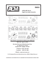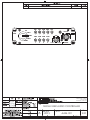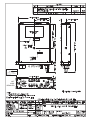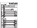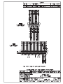
1
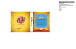
SPECIAL NOTICE
This product is now licensed to Anodyne Electronics Manufacturing (AEM) from Northern
Airborne Technology (NAT). AEM is responsible for all matters related to this product, including
sales, support and repair services.
Please note the transition to convert product manuals and supporting documentation is an
ongoing process and is being addressed on an ‘as needed’ basis.
All references to NAT product part numbers (and associated images) are equivalent to AEM
product part numbers.
Contact info:
Anodyne Electronics Manufacturing Corp.
#15-1925 Kirschner Road
Kelowna B.C. Canada
V1Y 4N7
Email: [email protected]
Toll Free: 1-888-763-1088
Phone: 1-250-763-1088
Fax: 1-250-763-1089
www.aem-corp.com
SM18
AA24/AA25 Series
Single User Audio Controller
INSTALLATION AND OPERATION MANUAL
REV 5.00 April 14, 2012
Anodyne Electronics Manufacturing Corp.
15-1925 Kirschner Road
Kelowna, BC Canada V1Y 4N7
Telephone: (250) 763-1088
Facsimile: (250) 763-1089
Website: www.aem-corp.com
© 2012 Anodyne Electronics Manufacturing Corp. (AEM), All Rights Reserved
CONFIDENTIAL AND PROPRIETARY TO ANODYNE ELECTRONICS MANUFACTURING CORP.
AA24/AA25 Series Single User Audio Controller Manual
SM18 Installation and Operation Manual
COPYRIGHT STATEMENT
© 2012 Anodyne Electronics Manufacturing Corp. (AEM), All Rights Reserved
This publication is the property of AEM and is protected by Canadian copyright laws. No
part of this document may be reproduced or transmitted in any form or by any means
including electronic, mechanical, photocopying, recording, or otherwise, without the prior
written permission of AEM.
Installation and Operation Manual
Page ii
ENG-FORM: 820-0100.DOTX
CONFIDENTIAL AND PROPRIETARY TO ANODYNE ELECTRONICS MANUFACTURING CORP.
AA24/AA25 Series Single User Audio Controller Manual
SM18 Installation and Operation Manual
Prepared By:
Checked By:
Approved By:
Tom Betzelt
Product Support
Manager
May 28, 2012
Loen Clement
Designer
May 25/12
Tony Pearson
Designer
Apr 14, 2012
The status of this installation and operation manual is controlled by the revision shown on the title page.
The status of each section is controlled by revision shown in the footer of each page. All revisions
affecting sections of this manual have been incorporated.
AEM MANUAL REVISIONS
Section
Revision Number
All
Rev: 5.00
Installation and Operation Manual
Revision Description
Updated drawings and template
Date
April 14, 2012
Page iii
ENG-FORM: 820-0100.DOTX
CONFIDENTIAL AND PROPRIETARY TO ANODYNE ELECTRONICS MANUFACTURING CORP.
AA24/AA25 Series Single User Audio Controller Manual
SM18 Installation and Operation Manual
Table of Contents
Section
Title
1.0
Description
1.1
1.2
1.3
1.4
1.4.1
1.4.2
1.4.3
1.5
Introduction
Purpose of Equipment
Features
Specifications
Electrical Specifications
Physical Specifications
Environmental Specifications
Unit Nomenclature
2.0
Installation
2.1
2.2
2.2.1
2.3
2.3.1
2.3.2
2.3.3
2.3.4
2.3.5
2.3.6
2.4
2.5
2.6
General
Unpacking and Inspection
Warranty
Installation Procedures
Warnings
Cautions
Cable and Wiring
Fuses and breakers
Ajustments
Post-Installation Checks
Continued Airworthiness
Accessories Required But Not Supplied
Installation Drawings
3.0
Operation
3.1
3.2
3.3
3.3.1
3.3.2
3.3.3
3.3.4
3.3.5
Introduction
General
Controls and Indicators
Transmit Selection
Receiver/Transceiver Selection
Volume Control
VOX Mode Control
Audio Alerting Functions
Installation and Operation Manual
Page
1-1
1-1
1-1
1-1
1-1
1-3
1-3
1-3
2-1
2-1
2-1
2-1
2-1
2-1
2-2
2-2
2-2
2-2
2-3
2-3
2-4
3-1
3-1
3-1
3-1
3-2
3-2
3-2
3-2
Page iv
ENG-FORM: 820-0100.DOTX
CONFIDENTIAL AND PROPRIETARY TO ANODYNE ELECTRONICS MANUFACTURING CORP.
AA24/AA25 Series Single User Audio Controller
SM18 Installation and Operation Manual
Section 1.0 Description
1.1
Introduction
This manual contains information on the AA24/AA25 Series Single User Audio Controllers. All derivatives
will be covered by manual supplements which can be obtained from AEM as required. Information in this
section consists of purpose of equipment, features and specifications.
1.2
Purpose of Equipment
The AA24/AA25 series single-user Audio Controllers support one headset per box. Connection to other users
in the system is made through the ICS Tie line. The small size and extensive radio and ICS functions make
this unit an excellent choice for multi-station aircraft.
The AA24/AA25 series systems provide full boom-mic transmit and ICS functions for the user. The front panel
controls permit user adjustment of frequently needed signals, such as intercom audio level, VOX threshold,
and individual radio receive levels. Internal adjustments set default values for direct audio level and artificial
side tone.
1.3
Features
The AA24/AA25 series single-user Audio Controllers support one headset per box. Connection to other
users in the system is made through the ICS Tie line. The small size and extensive radio and ICS
functions make this unit an excellent choice for multi-station aircraft.
The AA24/AA25 series systems provide full boom-mic transmit and ICS functions for the user. The front
panel controls permit user adjustment of frequently needed signals, such as intercom audio level, VOX
threshold, and individual radio receive levels. Internal adjustments set default values for direct audio level
and artificial side tone.
1.4
Specifications
1.4.1
Electrical Specifications
Power Supply:
Voltage
Current
Lighting
28Vdc (reverse and over voltage protection)
400 mA Max
28 Vdc @ 160 mA
Headset Power Phone output is nominal 600 Ω load
Short circuit protected
Typical 200 mW into headset
David Clark H10-30/40 series recommended
April 14, 2012 Rev: 5.00
Page 1-1
ENG-FORM: 800-0100.DOTX
CONFIDENTIAL AND PROPRIETARY TO ANODYNE ELECTRONICS MANUFACTURING CORP.
AA24/AA25 Series Single User Audio Controller
SM18 Installation and Operation Manual
Microphone
Industry standard ‘carbon equivalent’ type
250 mVrms for full output
Amplified dynamic microphone preferred
David Clark M1DC, M3, M4 recommended
(For low Z microphones, AA24-801 or AA25-801 are
recommended)
Indicators
Transmit (green LED)
VOX ICS triggered by ICS Tie Line (red LED)
Input Signals:
4 aircraft transceiver radio inputs
5 navigational receiver inputs
2.5 V rms for full output
4.7 kΩ input impedance
1 bi-directional ICS tie line
1 Vpp for full output
2.2 kΩ input impedance
Keylines
Transmit key is active low (33 mA of current)
Intercom key is active low (1 mA of current)
Intercom line
NAT ICS tie line compatible 2 kΩ input impedance
(340 mVrms level)
Output Signals:
Transmitter audio lines
Non-adjustable, microphone connected directly
to radio. (mic bias supplied by radio)
Transmitter key lines
Hard ground output (relay contacts 1 A
Max) Green LED annunciator
Intercom line
340 mVrms into 2 kΩ
(freq. Response +/- 6 dB from 250 to 4000 Hz)
Headset output
200 mW max. Into 600 ohms (floating output)
300 mW max. Into 150 ohms
Receive channel
freq. Response +/- 6 dB from 300 to 5000 Hz
Intercom channel
freq. Response +/- 6 dB from 225 to 5000 Hz
Direct input
freq. Response +/- 6 dB from 275 to 3100 Hz
Distortion
<2% THD
Isolation /crosstalk
>60 dB min
Signal/noise ratio
70 dB min
April 14, 2012 Rev: 5.00
Page 1-2
ENG-FORM: 800-0100.DOTX
CONFIDENTIAL AND PROPRIETARY TO ANODYNE ELECTRONICS MANUFACTURING CORP.
AA24/AA25 Series Single User Audio Controller
SM18 Installation and Operation Manual
1.4.2
Physical Specifications
Height
Depth (max)
Depth behind panel
Width (max)
Width behind panel
Weight
Mounting
1.4.3
AA24
1.49”
37.8mm
7.55”
191.8mm
5.84”
148.3mm
5.75”
146.0mm
4.9”
124.5mm
1.2 lbs
500g
Standard Dzus rails
AA25
2.62”
66.7mm
7.44”
188.8mm
5.83”
148.0mm
5.75”
146.0mm
4.9”
124.5mm
1.5 lbs
680g
Standard Dzus rails
Environmental Specifications
1.5
Temperature:
-40q C. to +70q C (operating)
-55q C. to + 85q C (survival)
Altitude
25,000 feet max
Humidity
95% Non-condensing
Shock
12 g (any axis)
Vibration
DO-160B category ‘P’, panel mounting 6g.
Unit Nomenclature
Model
Description / Distinction
AA24-001
COM1, COM2, COM3, COM4 + PA
NAV, ADF, DME, MKR, & AUX receive switches
+28 Vdc lights and +28 Vdc power
High impedance headset and mic
ICS, RX volume and VOX sq. Controls.
AA25-001
COM1, COM2, COM3, COM4 + PA
NAV, ADF, DME, MKR, & AUX receive switches
+28 Vdc lights and +28 Vdc power
High impedance headset and mic
ICS, RX volume and VOX sq. Controls.
End of Section 1.0
April 14, 2012 Rev: 5.00
Page 1-3
ENG-FORM: 800-0100.DOTX
CONFIDENTIAL AND PROPRIETARY TO ANODYNE ELECTRONICS MANUFACTURING CORP.
AA24/AA25 Series Single User Audio Controller
SM18 Installation and Operation Manual
Section 2.0 Installation
2.1
General
Information in this section consists of unpacking and inspection procedures, installation procedures, postinstallation checks, and installation drawings.
2.2
Unpacking and Inspection
Unpack the equipment carefully. Inspect the unit visually for damage due to shipping and report all such
claims immediately to the carrier involved. Note that each complete unit should have the following:
- AA24-001 or AA25-001 Audio Controller
- Product Information Card
- Release certification
Verify that all items are present before proceeding and report any shortage immediately to your
supplier.
2.2.1
Warranty
All Anodyne Electronics Manufacturing Corp. (AEM) products are warranted for 2 years. See the website
www.aem-corp.com/warranty for complete details.
2.3
Installation Procedures
2.3.1
Warnings
ÍIMPORTANT!
Do not bundle any lines from this unit with transmitter coax lines. Do not bundle any logic, audio
or DC lines from this unit with 400 Hz synchro wiring, or AC power lines. Do not position this unit
next to any device with a strong alternating magnetic field such as an inverter, motor or blower, or
significant interference to operation will result.
2.3.2
Cautions
In all installations, use shielded cable exactly as shown and ground as indicated. Significant problems
may result from not following these guidelines.
Do not ground the microphone or headphone jacks.
Do not connect the microphone and headphone shields together.
Use caution when routing microphone and ICS Tie Line wiring, as they are low level signals prone to
coupling form other sources.
April 14, 2012 Rev: 5.00
Page 2-1
ENG-FORM: 805-0100.DOTX
CONFIDENTIAL AND PROPRIETARY TO ANODYNE ELECTRONICS MANUFACTURING CORP.
AA24/AA25 Series Single User Audio Controller
SM18 Installation and Operation Manual
Do not take a ground from the instrument panel or similar location that shares a ground return with a turn
and bank, horizon or other motor driven instrument. This may cause the InterVox unit to pick up the
sound of the motor as ground loop interference.
For best results, all headsets/microphones in the system should be of the same type to avoid VOX
problems and uneven volume.
2.3.3
Cable and Wiring
All unshielded wire should be Tefzel MIL-M-22759/16 or equivalent. For shielded wire applications, use
Tefzel MIL-M-27500 shielded wire with solder sleeves (for shield terminations) to make the most compact
and easily terminated interconnect. Follow the wiring diagrams in Section 2.6 as required.
Allow 3" from the end of the wire to the shield termination to allow the connector hood to be easily
installed. Note that the hood is a "clamshell" hood, and is installed after the wiring is complete.
All wiring should be at least 22 AWG, except power and ground lines, which should be at least 20 AWG.
Ensure that the ground connection is clean and well secured.
2.3.4
Fuses and Breakers
Power protection should be provided through a 1.0 A breaker, and not attached to any other existing
breaker without additional protection.
2.3.5
Adjustments
See 3D drawing AA24\001\903-0 at the end of this section of the manual for the adjustment locations.
The unit ships from the factory with all internal adjustments set to the normal test levels. Once installed in
the aircraft, it may be desirable to change some of these settings to best suit the local operating
environment.
The Direct Audio level (DIR AUD LEVEL) and sidetone level (S/T LEVEL) can be adjusted at the time of
installation. The adjustment pots are accessed through holes in the upper cover, and can be rotated
clockwise to increase the level, and counterclockwise to decrease it.
2.3.6
Post-Installation Checks
2.3.6.1
Resistance Checks
Do not attach the AA24 or AA25 until the following conditions are met.
Check the following:
a) Check J101, pin <1> for +28 Vdc relative to ground.
b) Check J101, pin <9> for continuity to ground (less than 0.5Ω).
April 14, 2012 Rev: 5.00
Page 2-2
ENG-FORM: 805-0100.DOTX
CONFIDENTIAL AND PROPRIETARY TO ANODYNE ELECTRONICS MANUFACTURING CORP.
AA24/AA25 Series Single User Audio Controller
SM18 Installation and Operation Manual
2.3.6.2
Power On Checks
Install the AA24 or AA25 and power up the ship’s systems. Verify normal operation of all functions.
Refer to Section 3 for specific operation details.
a)
Run through all installed functions, and check the ICS and TX functions for all users.
b) Different headsets models may have significantly different mic characteristics, which will affect
‘VOX’ squelch settings. The David Clark M-7 mic is much more active than the M-4 or M-1 mics,
and may aggravate headset imbalance if used in a mixed system.
Note: Unusual buzzes, hums or other background audio are symptomatic of multiple grounds, or
noisy external systems such as blowers or pumps sharing wiring with the audio system. Failure
to key or correctly modulate a transmitter is often the result of forgetting to connect all required
grounds to the radio or external audio system.
c) To verify proper operation, all functions and levels should be checked in-flight.
If the unit functions satisfactory, make the required log entries and complete the required
MOT/FAA paperwork, before releasing the aircraft for service.
2.4
Continued Airworthiness
Maintenance of the AA24-001 or AA25-001 Single User Audio Controller is ‘on condition’ only. Periodic
maintenance of this product is not required.
2.5
Accessories Required But Not Supplied
Both the AA24 and the AA25 Seies Audio Controllers require Installation kit p/n AA24-IKC (crimp) or
AA24-IkS (solder) to complete the installation. They consist of the following:
AA24-IKC 37-pin and 15-pin D-min Female Crimp Kit (AEM Part No. D37S15SL-IKC)
Quantity
Description
AEM Part #
1
37
1*
1*
1
1
15
1*
1*
1
D-min 37 Socket Housing
MS Crimp Socket
Jack Screw Set
Lock Clip Set
37 Pin Connector Hood
D-min 15 Socket Housing
MS Crimp Socket
Jack Screw Set
Lock Clip Set
15 Pin Connector Hood
20-21-037
20-26-901
20-27-002
20-27-004
20-29-038
20-21-015
20-26-901
20-27-002
20-27-004
20-29-015
*Use as required.
April 14, 2012 Rev: 5.00
Page 2-3
ENG-FORM: 805-0100.DOTX
CONFIDENTIAL AND PROPRIETARY TO ANODYNE ELECTRONICS MANUFACTURING CORP.
AA24/AA25 Series Single User Audio Controller
SM18 Installation and Operation Manual
AA25-IKC 37-pin and 15-pin D-min Female solder Kit (AEM Part No. D37S15SL-IKS)
Quantity
Description
AEM Part #
1
1*
1*
1
1
1*
1*
1
D-min 37 Socket Housing
Jack Screw Set
Lock Clip Set
37 Pin Connector Hood
D-min 15 Socket Housing
Jack Screw Set
Lock Clip Set
15 Pin Connector Hood
20-21-037
20-27-002
20-27-004
20-29-038
20-21-015
20-27-002
20-27-004
20-29-015
*Use as required.
2.6
Installation Drawings
DRAWING
AA24-001
AA24-001\403-0
AA24-001\405-0
AA24-001\905-0
AA24-001\922-0
REV
1.01
1.02
2.00
1.02
AA25-001
AA25-001\403-0
AA25-001\405-0
AA25-001\905-0
AA25-001\922-0
1.10
1.02
1.01
1.01
DESCRIPTION
TYPE
SERIAL #
Single User Audio Controller
Single User Audio Controller
Single User Audio Controller
Single User Audio Controller
Interconnect
Connector Map
Faceplate
Mech. Installation
1128 and up
All
All
All
Single User Audio Controller
Single User Audio Controller
Single User Audio Controller
Single User Audio Controller
Interconnect
Connector Map
Faceplate
Mech. Installation
1057 and up
All
All
All
Section 2.0 ends following the above drawings
April 14, 2012 Rev: 5.00
Page 2-4
ENG-FORM: 805-0100.DOTX
CONFIDENTIAL AND PROPRIETARY TO ANODYNE ELECTRONICS MANUFACTURING CORP.
2.00
RAS#34 - CHANGED TO AEM LOGO, UPDATED HOLE SCHEDULE.
NAV
PA
ADF
DME
MKR
15-Dec-11
MWS
AUX
RX VOL
COM1
AA24
COM2
COM
COM
COM
COM
1
2
3
4
VOX
COM3
COM4
LIVE
PTT
ICS VOL
KELOWNA BC CANADA
(250)-763-1088
WWW.AEM-CORP.COM
29 Dec. 11
Dec 29/11
SINGLE USER AUDIO CONTROLLER
REV
SIZE
A
AA24-001
L9015
1:1
905-0
2.00
SHEET 1 of 3
Reviewed/Approved
Tony Pearson
Designer
Jun 22, 2011
NAT
LOGO
REMOVED
Reviewed/Approved
Tony Pearson
Designer
Jul 4, 2011
REMOVE
NAT
LOGO
Reviewed/Approved
Tony Pearson
Designer
Jul 4, 2011
NAT LOGO
REMOVED
AA24/AA25 Series Single User Audio Controller
SM18 Installation and Operation Manual
Section 3.0 Operation
3.1
Introduction
Information in this section consists of the functional and operational procedures for the AA24/AA25 Series
Single User Audio Controller.
3.2
General
The AA24/AA25 series single user audio controllers allow selection of transmit and receive audio, and
LIVE, VOX or PTT intercom. One direct alerting input is provided to allow emergency alerting audio to
pass unmated to the user’s headset. After transmitting on the radios the user’s microphone automatically
reverts back to intercom mode. The AA25 audio controller also provides central volume adjustment for all
the aircraft audio.
3.3
Controls and Indicators
3.3.1
Transmit selection
The rotary selector switch at the lower left of the panel selects the desired transmit function. When the
radio PTT switch is activated, the microphone will be coupled to the radio or PA channel selected.
Receive audio is automatically selected with the transmit selection, and no additional switching is needed
to establish outside communication.
During transmission, the TX annunciator LED on the front panel will illuminate green.
April 14, 2012 Rev: 5.00
Page 3-1
ENG-FORM: 806-0100.DOTX
CONFIDENTIAL AND PROPRIETARY TO ANODYNE ELECTRONICS MANUFACTURING CORP.
AA24/AA25 Series Single User Audio Controller
SM18 Installation and Operation Manual
3.3.2
Receiver/Transceiver Selection
The Receiver/Transceiver audio is selected from a double row of color-coded toggle switches. Receiver
switch bats are blue, and the transceiver switch bats are white. To connect the desired radio to the
headphones, the relevant switch is toggled upwards.
On the AA25, independent volume controls are provided for the transceivers and the first two NAV aids.
3.3.3
Volume Control
The Volume control is a dual concentric knob.
3.3.3.1 ICS Volume Control
The inner knob of the dual control is ICS VOL and controls the intercom volume for all headsets. An
internal trimpot sets the minimum level. With ICS VOL set fully ccw intercom volume will be at a
minimum. As the operator rotates the control cw, intercom volume will increase.
In multiple station systems, the ICS volume adjusts only the local ICS audio level.
3.3.3.2 RX Volume Control
The outer knob of the dual control is RX VOL and controls the RX volume for all selected radios. With RX
VOL fully ccw, volume will be at a minimum. As the operator rotates the control cw, volume will increase.
3.3.4
VOX Mode Control
The VOX Control selects the mode of operation of the intercom mic. When the control is in the centre of
its range, the intercom is in the VOX mode (voice activated). As the control is rotated counterclockwise,
the system becomes more sensitive, until in the fully counterclockwise position it is in LIVE mode (on
constantly). As the control is rotated clockwise, the sensitivity decreases, until at the fully clockwise
position it is in PTT mode (activated by cyclic or foot switch closure).
3.3.5
Audio Alerting Functions
The user receives audio alerting signals connected to the Direct Audio under all operating conditions of
the AA24/AA25.
End of Section 3.0
April 14, 2012 Rev: 5.00
Page 3-2
ENG-FORM: 806-0100.DOTX
CONFIDENTIAL AND PROPRIETARY TO ANODYNE ELECTRONICS MANUFACTURING CORP.