1
USER’S GUIDE
VFX5112/5212 Guitar Amplifier
Table of Contents:
The Front Panel...................................................................................4
The Rear Panel ....................................................................................5
Using the Footswitch to Save DSP Settings ....................................5
Important Information About Tubes and Tube Products
A Brief History Of The Tube ..........................................................6
Tube Types and Usage................................................................6,7
The Nature of Tubes: Why (and When) to Replace Them .......7,8
The Importance of Proper Biasing................................................8
Survival Tips For Tube Amplifiers ................................................9
Suggested Setting.............................................................................10
System Block Diagram .....................................................................11
Technical Specifications ...................................................back cover
CAUTION
PRECAUCION
ATTENTION
RISK OF ELECTRIC SHOCK
DO NOT OPEN
RIESGO DE CORRIENTAZO
NO ABRA
RISQUE D'ELECTROCUTION
NE PAS OUVRIR
WARNING: TO REDUCE THE RISK OF FIRE OR ELECTRIC
SHOCK, DO NOT EXPOSE THIS APPARATUS TO RAIN OR MOISTURE. TO REDUCE THE RISK OF ELECTRIC SHOCK, DO NOT
REMOVE COVER. NO USER-SERVICEABLE PARTS INSIDE.
REFER SERVICING TO QUALIFIED SERVICE PERSONNEL.
PRECAUCION: PARA REDUCIR EL RIESGO DE INCENDIOS O DESCARGAS
ELECTRICAS, NO PERMITA QUE ESTE APARATO QUEDE EXPUESTO A LA
LLUVIA O LA HUMEDAD. PARA DISMINUOIR EL RIESGO DE CORRIENTAZO.
NO ABRA LA CUBIERTA. NO HAY PIEZAS ADENTRO QUE EL USARIO PUEDO
REPARAR DEJE TODO MANTENIMIENTO A LOS TECHNICOS CALIFICADOS.
ATTENTION: PROTÉGEZ CET APPAREIL DE LA PLUIE ET DE L'HUMIDITÉ
AFIN D'ÉVITER TOUT RISQUE D'INCENDIE OU D'ÉLECTROCUTION. POUR
REDUIRE D'ELECTROCUTION NE PAS ENLEVER LE COUVERCLE. AUCUNE
PIECE INTERNE N'EST REPRABLE PAR L'UTILISATEUR. POUR TOUTE
REPARATION, S'ADRESSER A UN TECHNICIEN QUALIFIE.
IMPORTANT SAFETY INSTRUCTIONS
• READ, FOLLOW, HEED, AND KEEP ALL INSTRUCTIONS AND WARNINGS.
• DO NOT OPERATE NEAR ANY HEAT SOURCE AND DO NOT BLOCK ANY VENTILATION OPENINGS ON THIS APPARATUS. FOR
•
•
•
•
•
•
•
•
•
PROPER OPERATION, THIS UNIT REQUIRES 3” (75mm) OF WELL VENTILATED SPACE AROUND HEATSINKS AND OTHER AIR
FLOW PROVISIONS IN THE CABINET.
DO NOT USE THIS APPARATUS NEAR SPLASHING, FALLING, SPRAYING, OR STANDING LIQUIDS.
CLEAN ONLY WITH LINT-FREE DAMP CLOTH AND DO NOT USE CLEANING AGENTS.
ONLY CONNECT POWER CORD TO A POLARIZED, SAFETY GROUNDED OUTLET WIRED TO CURRENT ELECTRICAL CODES AND
COMPATIBLE WITH VOLTAGE, POWER, AND FREQUENCY REQUIREMENTS STATED ON THE REAR PANEL OF THE APPARATUS.
PROTECT THE POWER CORD FROM DAMAGE DUE TO BEING WALKED ON, PINCHED, OR STRAINED.
UNPLUG THE APPARATUS DURING LIGHTNING STORMS OR WHEN UNUSED FOR LONG PERIODS OF TIME.
ONLY USE ATTACHMENTS, ACCESSORIES, STANDS, OR BRACKETS SPECIFIED BY THE MANUFACTURER FOR
SAFE OPERATION AND TO AVOID INJURY.
WARNING: TO REDUCE THE RISK OF ELECTRIC SHOCK OR FIRE, DO NOT EXPOSE THIS UNIT TO RAIN OR MOISTURE.
SERVICE MUST BE PERFORMED BY QUALIFIED PERSONNEL.
OUR AMPLIFIERS ARE CAPABLE OF PRODUCING HIGH SOUND PRESSURE LEVELS. CONTINUED EXPOSURE TO HIGH SOUND
PRESSURE LEVELS CAN CAUSE PERMANENT HEARING IMPAIRMENT OR LOSS. USER CAUTION IS ADVISED AND EAR PROTECTION IS RECOMMENDED IF UNIT IS OPERATED AT HIGH VOLUME.
EXPLANATION OF GRAPHICAL SYMBOLS:
EXPLICACION DE SIMBOLOS GRAFICOS:
EXPLICATION DES SYMBÔLES GRAPHIQUES:
2
"DANGEROUS VOLTAGE"
=
“VOLTAJE PELIGROSO”
"DANGER HAUTE TENSION"
"IT IS NECESSARY FOR THE USER TO REFER TO THE INSTRUCTION MANUAL"
=
“ES NECESARIO QUE EL USUARIO SE REFIERA AL MANUAL DE INSTRUCCIONES.”
"REFERREZ-VOUS AU MANUAL D'UTILISATION"
VFX5112/5212 Guitar Amplifier
Congratulations!
You are now the proud owner of a V-Series VFX Guitar Amplifier. These
combo amplifiers combine incredible vintage tube sound with 15 outstanding digital effects – giving you a powerful tube amplifier that’s easy to operate yet still produces incredible sounds!
Like all St. Louis Music amplifiers, your VFX is designed by musicians, and
built using the finest components available. Extensive testing confirms that
this amplifier is the absolute best it can be.
In order to get the most out of your new amplifier, we strongly urge you to
read the information contained in this manual before you begin playing.
And Thank You for choosing a V-Series amplifier!
Declaration Of Conformity
#35, Effective 01-01-2001
Manufacturer’s Name:
Production Facility:
Production Facility:
Shipping Facility:
Office Facility:
SLM Electronics
11880 Borman Drive, St. Louis, MO 63146, USA
700 Hwy 202 W, Yellville, AR 72687, USA
1400 Ferguson Ave., St. Louis, MO 63133, USA
1400 Ferguson Ave., St. Louis, MO 63133, USA
Product Type:
Audio Amplifier
Complies with Standards:
LVD:
Safety:
EMC:
92/31/EEC, 93/68/EEC, & 73/23/EWG
EN60065
EN55013, EN55020, EN55022, EN61000-3-2,
& EN61000-3-3
Supplementary information provided by your local Sales & Services Office or:
SLM Electronics - R & D Engineering
1901 Congressional Drive, St Louis, MO 63146, USA
Tel.: 314-569-0141, Fax: 314-569-0175
3
VFX5112/5212 Guitar Amplifier
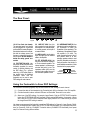
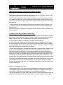
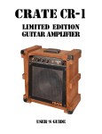
The Front Panel:
INPUT
VOLUME
TREBLE
MID
BASS
GAIN
TREBLE
MID
BASS
Level
Mode
T-WAH
SLAP
CHORUS
CHO•REV•
DELAY
BYPASS
CHO•
REV
10
0
10
0
10
0
10 Channel 0
Select
Channel A
1
2
3
4
5
1. Input: Connect your instrument
here by means of a shielded signal
cable.
2.. Volume: Use this control to
adjust the output level of Channel
A.
3. Treble: Use this control to adjust
the output level of the high frequencies for Channel A. This control
provides an adjustment range of
30dB at 10kHz.
4. Mid: Use this control to adjust
the output level of the middle frequencies for Channel A. This control provides an adjustment range
of 6dB at 600Hz.
5. Bass: Use this control to adjust
the output level of the low frequencies for Channel A. This control provides an adjustment range of 30dB
at 80Hz.
6. Channel Select: This switch,
when depressed, activates
Channel B. Channel A is active
when the switch is in the out position.
7. Gain: Use this control to adjust
the gain for Channel B. With the
control towards the counter clockwise position, the gain is low and
very little distortion is present. As
you rotate the control clockwise the
gain increases, producing more
overdrive distortion and a higher
output volume level.
4
6
10
0
10
0
10
0
10
0
10
Channel B
7
8
9
10
11
VFX
On
On
Standby
Off
16
17
DELAY 1
VIBRATO
DELAY•
FAST
REV 1
DELAY
VIBRATO
2
SLOW DELAY•
REV 2
12
8. Treble: Use this control to adjust
the output level of the high frequencies for Channel B. This control
provides an adjustment range of
10dB at 4kHz.
9. Mid: Use this control to adjust
the output level of the middle frequencies for Channel B. This control provides an adjustment range
of 10dB at 1kHz.
10. Bass: Use this control to adjust
the output level of the low frequencies for Channel B. This control
provides an adjustment range of
12dB at 100Hz.
11. Level: Use this control to adjust
the output level of Channel B.
12. DSP Mode: Use this control to
select which of the following digital
effects to apply to the signal.
BYPASS
SMALL REV
MED REV
LARGE REV
SLAPBACK
DELAY 1
DELAY/REV 1
DELAY 2
DELAY/REV 2
VIBRATO SLOW
VIBRATO FAST
CHORUS
CHO/REV
CHO/REV/DELAY
SLAP CHORUS
T-WAH
Presence
Level
SLAP
BACK
CHORUS
0
DSP
SMALL
REV
MED
REV
LARGE
REV
no effect
small room reverb
medium room reverb
large hall reverb
short slapback echo
short delay w/regen
short delay w/reverb
long delay w/regen
long delay w/reverb
slow smooth vibrato
fast vibrato/tremolo
medium chorus
medium chorus w/reverb
med cho w/reverb/delay
slapback echo w/chorus
touch-sensitive wah-wah
0
10
0
10
Master
13
14
15
13. DSP Level: Use this control to
adjust the level of the DSP effect.
With the control rotated fully counter clockwise, no effect will be audible. As the control is rotated clockwise the amount of the effect is
increased.
14. Presence: Use this control to
adjust the overall brightness and
punch of the output signal.
15. Lamp: This lamp illuminates
when the amplifier is turned on.
16. On/Standby Switch: Use this
switch to activate the amplifier after
the On/Off Switch (#17) is turned
on. Always turn this switch OFF
first and ON last! Turn the
On/Off Switch (#17) on at least
30 seconds before turning on
the Standby switch. During short
breaks you should turn this switch
off and leave the On/Off Switch on.
This will help prolong the life of the
amplifier’s tubes.
17. On/Off Switch: Use this switch
to turn the amplifier on and off.
Always turn this switch ON first
and OFF last! Turn the Standby
switch (#16) on at least 30 seconds after turning on the On/Off
Switch.
VFX5112/5212 Guitar Amplifier
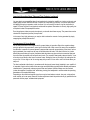
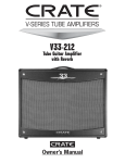
The Rear Panel:
ST. LOUIS MUSIC, INC.
18
18. AC Line Cord (not shown):
The grounded power cord should
only be plugged into a grounded
power outlet that meets all applicable electrical codes and is compatible with the voltage, power, and
frequency requirements stated on
the rear panel. Do not attempt to
defeat the safety ground connection.
19. FOOTSWITCH JACK: Use
this jack to connect the cable of the
footswitch (supplied) for remote
control of channel switching and
the DSP effect. (Tip = channel
select, ring = DSP select.) Refer to
the section below for additional
information about how the
footswitch can be used to save
DSP settings fro each channel.
FOOTSWITCH
LINE OUT
LINE IN
EXT. SPEAKER
19
20
21
22
IMPEDANCE
20. LINE OUT JACK: Use this
jack to send a line level signal from
the amplifier to an external amplifier, a mixing console, or the input of
an external effect.
21. LINE IN JACK: Use this jack to
return the signal from an external
effect to the amplifier.
22. EXT. SPEAKER JACK: Use
this jack to connect the amplifier to
a 16 ohm extension speaker. The
internal speaker is not disconnected when this jack is in use. The
impedance switch (#23) must be
set to the 8 ohm position when a 16
ohm extension speaker is used.
23
23. IMPEDANCE SWITCH: Use
this switch to set the amplifier’s output impedance to match the
impedance of the speaker(s). The
impedance of the speaker(s) inside
the amplifier is 16 ohms. The
switch is set at the factory to the 16
ohm position. When a 16 ohm
extension speaker cabinet is used
(see #22), this switch must be set to
the 8 ohm position. Use the tip of a
small flatblade screwdriver to slide
the switch to the proper position.
8 OHM
POSITION
16 OHM
POSITION
Impedance switch as seen from below
Using the Footswitch to Save DSP Settings:
The two-button footswitch (supplied) may be used to save two DSP settings for each channel.
(1) Connect the cable of the footswitch to the Footswitch jack (#19) on the back of the VFX amplifier.
(2) Click the footswitch buttons until both LEDs are not illuminated. Channel A is now active.
(3) Select one of the DSP settings - for example, Large Reverb. Click the “EFFECTS A/B” footswitch
button (the EFFECTS A/B LED will illuminate). Select another DSP setting - for example, Vibrato
Slow. Click the “EFFECTS A/B” footswitch button again (the #EFFECTS A/B LED will go out) and
the Large Reverb DSP setting is recalled.
You have now programmed the footswitch to recall two DSP settings for Channel A: Large Reverb (CHANNEL LED not illuminated) and Vibrato Slow (EFFECTS A/B LED illuminated). You may repeat this procedure for Channel B. Click the “CHANNEL” footswitch button (CHANNEL LED illuminated), then repeat
step 3 for Channel B using different effects.
5
VFX5112/5212 Guitar Amplifier
Important Information About Tubes and Tube Products:
A Brief History Of The Tube:
In 1883, Edison discovered that electrons would flow from a suspended filament when enclosed in an evacuated lamp. Years later, in 1905, Fleming expanded on Edison's discovery and created the "Fleming Valve".
Then, in 1907, Dr. Lee de Forest added a third component – the grid – to the "Fleming's Valve" and the vacuum tube was a fact of life. The door to electronic amplification was now open.
During World War II, data gleaned from their intensive research on the detectors used in radar systems led
Bell Telephone Laboratories to the invention of the transistor. This reliable little device gained quick support
as the new component for amplification. The death of the vacuum tube seemed imminent as designers, scientists, and engineers reveled in the idea of replacing large, fragile glass tubes with these small, solid-state
devices.
However, there were (and still are) many serious listeners who realized that the sound produced by a "transistor" amplifier is significantly different from that produced by a tube amplifier with identical design specifications. They considered the sound produced by these new solid-state devices to be hard, brittle, and lifeless.
It was determined that solid-state devices produced a less musical set of harmonics than tubes. When pushed
past their limits, they tend to mute the tone and emphasize the distortion.
Tubes, on the other hand, produce a more musical set of harmonics, the intensity of which can be controlled
by the player. This characteristic adds warmth and definition to the sound which has become the hallmark of
tube amplifiers. When tubes are driven into clipping, the harmonic overtones can be both sweet and pleasing
or intense and penetrating, depending on the musician’s musical taste and playing technique.
Over the years, application engineers have designed a number of outstanding solid-state amplifiers that
sound very, very good. Some use special circuitry which enables them to simulate the distortion characteristics of a tube amplifier. However, the tube amplifier, still held in the highest esteem by many musicians, offers
a classic "vintage" sound in a contemporary market.
Tube Types And Usage:
Tube amplifiers are based primarily on two types of tubes – preamplifier tubes and power tubes. The tubes
used in preamplifiers (12AX7, 12AU7, 12AT7, etc.) are smaller than the power tubes. These tubes amplify
the signal from your instrument and shape the sound. They are inherently microphonic (mechanically pick
up and transmit external noises). Since these tubes are used in the critical first stages of a tube amplifier's
circuitry, it is very important to use high-quality, low noise/low microphonic tubes for this application.
Although tubes of this quality may be difficult to find and typically cost more than "off-the-shelf" tubes, the
improvement in performance is worth the investment.
Preamplifier tubes are also used to drive the power tubes. When used in this application, a 12AX7 will produce a more distorted tone than a 12AT7, which produces a clearer, sweeter sound. A 12AU7 is even
cleaner and brighter than a 12AT7, giving more definition to the sound. (In some cases it is possible to
change the sound by changing the type of preamp and/or driver tubes. When making any modification to
your equipment, it is highly recommended that you consult with a qualified service center.)
The power tubes are the largest tubes used in an amplifier. These tubes convert the low-level, conditioned
signal from the preamplifier into a level that is sufficient to drive the speakers. There are several types of
power tubes available, each of which offers a different performance/sound characteristic. For example, the
EL34 power tube produces a great Classic rock sound. When an EL34 is driven into distortion it produces a
unique sound ("crunch"). When compared to the EL84 and 6L6, the EL34 distorts more quickly, exhibits a
6
VFX5112/5212 Guitar Amplifier
Important Information About Tubes and Tube Products (continued):
"looser" low-end response and produces more harmonics at mid and high frequencies ("creamier" sound).
These differences become more noticeable at higher volumes.
The EL84 and 6L6 tubes produce a big low-end thump and have a very good dynamic range. They offer a
more traditional "American Rock" sound. The EL84 and 6V6 tubes produce a creamy sound with nice distortion. On the other hand, the KT88 produces a big low-end but sounds more like an EL34 in the mid and
high frequencies.
The 6550 power tubes are more rugged and stay cleaner sounding even at full power. When they do distort, the sound produced is more solid and has a tighter low end; more of a "heavy metal" type distortion
with lots of power.
Some tubes are available in matched sets. These tubes have been extensively tested for optimum performance and longevity.
The Nature Of Tubes: Why (And When) To Replace Them:
Tubes are made up of a number of fragile mechanical components that are vacuum-sealed in a glass envelope or bubble. The tube's longevity is based on a number of factors which include how hard and often the
amplifier is played, vibration from the speakers, road travel, repeated set up and tear down, etc.
Any time you notice a change in your amplifier's performance, check the tubes first.
If it's been a while since the tubes were replaced and the sound from your amplifier lacks punch, fades in
and out, loses highs or lows or produces unusual sounds, the power tubes probably need to be replaced. If
your amplifier squeals, makes noise, loses gain, starts to hum, lacks "sensitivity", or feels as if it is working
against you, the preamplifier tubes may need to be replaced.
The power tubes are subjected to considerably more stress than the preamplifier tubes. Consequently, they
almost always fail/degrade first. If deteriorating power tubes aren't replaced they will ultimately fail.
Depending on the failure mode, they may even cause severe damage to the audio output transformer
and/or other components in the amplifier. Replacing the tubes before they fail completely has the potential
to save you time, money and unwanted trouble. Since power tubes work together in an amplifier, it is crucial that they (if there is more than one) be replaced by a matched set. If you're on the road a lot, we recommend that you carry a spare matched set of replacement power tubes and their associated driver tubes.
After turning off the power and disconnecting the amplifier from the power source, carefully check the tubes
(in bright light) for cracks or white spots inside the glass or any other apparent damage. Then, with the
power on, view the tubes in a dark room. Look for preamplifier tubes that do not glow at all or power tubes
that glow excessively red.
Whenever you replace the power tube(s):
• Always have the amplifier's bias voltage checked by a qualified service center. Improper bias voltage will
cause degradation in performance and possibly damage the tubes and/or the amplifier. (See the section
below entitled, "The Importance of Proper Biasing", for more information on this subject).
• We highly recommend that you replace the driver tube(s) as well. The driver tube determines the shape and
amplitude of the signal applied to the power tube(s) and has to work almost as hard as the power tube(s).
7
VFX5112/5212 Guitar Amplifier
Important Information About Tubes and Tube Products (continued):
You can check your preamplifier tubes for microphonics by turning the amplifier on, turning up the gain and
tapping lightly on each tube with the end of a pencil or a chop stick (my favorite). You will be able to hear
the tapping through your speakers, which is normal. It is not normal for a tube to ring like a bell after it’s
tapped. If it does ring then it’s microphonic and should be replaced. Remember to use only high quality, low
microphonic tubes in the preamplifier section.
Even though power tubes are rarely microphonic, you should check them anyway. The power tubes can be
checked for microphonics just like pre-amp tubes.
In the case of very high gain amps, you may be able to reduce the amount of noise generated by simply
swapping the preamp tubes around.
The Importance Of Proper Biasing:
For the best performance and longest tube life, proper biasing is imperative. Bias is the negative voltage
which is applied to the power tube’s control grid to set the level of idle current. We cannot over emphasize
the difference in warmth of tone and dynamic response that come with proper biasing. If the bias is set too
high (overbiased), the sound from the amp will be distorted at all levels. If the bias is set too low, (under
biased) the power tubes will run hot (the plates inside the tubes may glow red due to excessive heat) and
the sound from the amplifier will lack power and punch. The excessive heat greatly reduces tube life – from
a few days to as little as a few hours in extreme cases. Setting the bias on your amp is like setting the idle
on your car. If it’s too high or hot it’s running away with you and if it’s too low or cold it will choke when you
step on it.
The bias is adjusted at the factory in accordance with the type of power tube(s) installed in your amplifier. It
is important to point out that tubes of the same type and specification typically exhibit different performance
characteristics. Consequently, whenever power tubes are replaced, the bias voltage must be checked
(unless the amplifier is equipped with "self-biasing circuitry) and readjusted to accommodate the operating
parameters of the replacement tubes.
Depending on the model and amplifier type, there may be hum balance controls, trim pots, or bias adjustment controls on its rear panel. However, the bias adjustment should be performed only by qualified service
personnel with the proper, calibrated test equipment.
8
VFX5112/5212 Guitar Amplifier
Important Information About Tubes and Tube Products (continued):
Survival Tips For Tube Amplifiers:
To prolong tube life, observe these tips and recommendations:
• Match the impedance of your speaker cabinet(s) to your amplifier. Improper impedance matching will contribute to early tube degradation and may cause premature tube failure.
• Make sure the speaker(s) are properly connected prior to turning on the amplifier.
• After playing the amplifier, allow sufficient time for it to properly cool down prior to moving it. A properly
cooled amplifier prolongs tube life due to the internal components being less susceptible to the damage
caused by vibration.
• Allow the amplifier to warm up to room temperature before turning it on. The heat generated by the tube
elements can crack a cold glass housing.
• Replace the output tube(s) before the performance degrades or the tubes fail completely. Replace the
tube(s) on a regular basis (at least once per year or as often as every 4 to 6 months if you play long and
hard every day).
• Always have the bias checked after replacing the output tubes (unless the amplifier is equipped with "selfbiasing circuitry"). This should be done ONLY at a qualified service center. Improper biasing could result
in the tubes running too hot, which greatly reduces the life of the tubes – or too cold, which results in distorted sound regardless of level settings. Do not play the amplifier if it exhibits these symptoms – get the
bias checked/adjusted immediately to prevent tube failure and/or other damage.
• If the locating notch on the base of a power tube breaks off, replace the tube. This significantly reduces
the risk of damaging your amplifier by incorrectly inserting the tube.
• Protect the amplifier from dust and moisture. If liquid gets into the amplifier proper, or if the amplifier is
dropped or otherwise mechanically abused, have it checked out at an authorized service center before
using it.
• Proper maintenance and cleaning in combination with routine checkups by your authorized service center
will insure the best performance and longest life from your amplifier.
CAUTION: Tube replacement should be performed only by qualified service personnel who are
familiar with the dangers of hazardous voltages that are typically present in tube circuitry.
9
VFX5112/5212 Guitar Amplifier
Suggested Settings:
Clean:
VOLUME
Low Volume Buzz:
TREBLE
MID
BASS
GAIN
TREBLE
MID
BASS
Level
Mode
T-WAH
SLAP
CHORUS
CHO•REV•
DELAY
BYPASS
CHO•
REV
10
0
10
0
10
0
10 Channel 0
Select
Channel A
Bluesy Crunch:
VOLUME
TREBLE
10
0
10
0
10
0
10
0
10
Channel B
DELAY 1
VIBRATO
DELAY•
FAST
REV 1
DELAY
VIBRATO
2
SLOW DELAY•
REV 2
MID
BASS
GAIN
TREBLE
MID
BASS
Level
Mode
BYPASS
CHO•
REV
0
10
0
10
0
10 Channel 0
Select
Channel A
Sparkly Clean:
VOLUME
TREBLE
10
0
10
0
10
0
10
0
10
Channel B
MID
BASS
GAIN
TREBLE
MID
BASS
Level
10
0
Channel A
10
10
Presence
Level
SLAP
BACK
DELAY 1
Mode
CHO•
REV
0
0
0
10
0
10
Master
Uh-Oh!:
CHORUS
10
DSP
VIBRATO
DELAY•
FAST
REV 1
DELAY
VIBRATO
2
SLOW DELAY•
REV 2
T-WAH
SLAP
CHORUS
CHO•REV•
DELAY
0
10
SMALL
REV
MED
REV
LARGE
REV
CHORUS
10
0
Master
Crunchy Rhythm:
T-WAH
SLAP
CHORUS
CHO•REV•
DELAY
0
Presence
Level
SLAP
BACK
CHORUS
0
DSP
SMALL
REV
MED
REV
LARGE
REV
10
0
10 Channel 0
Select
10
0
10
0
10
Channel B
0
10
0
10
BYPASS
DSP
Presence
Level
SMALL
REV
MED
REV
LARGE
REV
SLAP
BACK
DELAY 1
VIBRATO
DELAY•
FAST
REV 1
DELAY
VIBRATO
2
SLOW DELAY•
REV 2
0
Master
10
0
10
VFX5112/5212 Guitar Amplifier
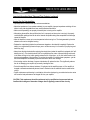
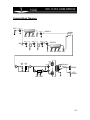
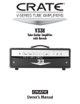
System Block Diagram:
INPUT V1A
V1B
CHANNEL A
CHANNEL
SELECT
BASS MID TREBLE VOL
V2A
V2B
V3A
V3B
CHANNEL B
GAIN
BASS MID TREBLE LEVEL
EL34
V5
LINE LINE
OUT IN
V4A
IMPEDANCE
SELECT
SPEAKER
DSP
V4B
EL34
V6
EXT.
SPEAKER
MODE LEVEL
11
VFX5112/5212 Guitar Amplifier
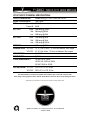
VFX 5112/5212 TECHNICAL SPECIFICATIONS:
OUTPUT POWER RATING
SIGNAL TO NOISE RATIO
GAIN
Channel A:
Channel B:
EQ - CH. A
Treble:
Mid:
Low:
EQ - CH. B
Treble:
Mid:
Low:
PRESENCE
SPEAKER SPECS VFX 5112:
VFX 5212:
PREAMP TUBES
POWER TUBES
POWER REQUIREMENTS
50Watts RMS @ 5 % THD 16 ohm load 120 VAC
70dB Typical
62 dB
98 dB
30dB range @ 10kHz
6dB range @ 600Hz
30dB range @ 80Hz
10dB range @ 4kHz
10dB range @ 1kHz
12dB range @ 100Hz
18dB range @ 20kHz
1 X 12”, 60w, 16 ohm, 1.75” voice coil diameter, 38oz. magnet
2 X 12”, 60w, 8 ohm, 1.75 voice coil diameter, 38oz. magnet
(4) 12AX7A
(2) EL34
120 VAC, 60 Hz, 200VA
100/115 VAC, 50/60 Hz, 200VA
230 VAC, 50/60 Hz, 200VA
SIZE AND WEIGHT VFX 5112: 23”W x 19” H x 10”D, 48 lbs.
VFX 5212: 28”W x 21” H x 11”D, 58 lbs.
The VFX 5112/5212 is covered with a durable Tolex material: wipe it clean with a lint-free cloth.
Never spray cleaning agents onto the cabinet. Avoid abrasive cleansers which would damage the finish.
Specifications and information in this manual are subject to change without notice.
www.v-seriesamps.com
@2002 St. Louis Music, Inc • 1400 Ferguson Avenue • St. Louis, MO 63133
47-036-03 • 062503