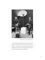
1
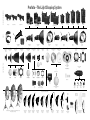
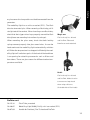
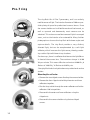
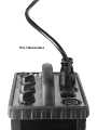
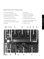
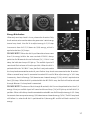
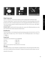
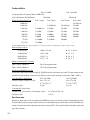
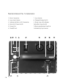
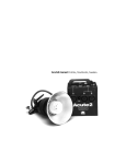
Pro-7 Manual Profoto, Stockholm, Sweden.
Safety Instructions
Profoto generators and flash heads are part of a complete professional lighting system.
Please read the instruction manual carefully before use. Flash tubes and modelling lights
emit considerable heat and can be dangerous if not used properly. Always unplug the lamp
cable from the generator before changing modelling light, glass cover or flash tube.
Under no circumstances are generators or heads to be opened! There is high voltage inside
.
..
..
..
..
the generator! Service is only to be carried out by authorised personnel.
Never connect accessories of other brands without consulting an
authorised service station.
Do not touch hot glass or metal parts.
Do not obstruct ventilation.
Do not connect the lamp head with the transport cap in place.
Never place filters or diffusing material directly onto glass covers, flash tubes or
modelling lights.
Never position the light extremely close to people.
When mounting umbrellas, do not touch flash tubes or modelling lights
with the metal shaft – risk of high voltage.
Always use a grounded power supply/mains outlet.
Protect the flash equipment against moisture, condensation, heat, sand and dirt.
Contents
Introduction . . . . . . . . . . . . . . . . . . . . . . . . . . . . 4
Accessories . . . . . . . . . . . . . . . . . . . . . . . . . . 6 - 7
ProHead . . . . . . . . . . . . . . . . . . . . . . . . . . . . . . 8
Pro-7b head . . . . . . . . . . . . . . . . . . . . . . . . . . . . 9
ProTwin . . . . . . . . . . . . . . . . . . . . . . . . . . . 10 - 11
Pro-7 ring . . . . . . . . . . . . . . . . . . . . . . . . . . . . 12
Pro-7a 1200/2400 . . . . . . . . . . . . . . . . . . . 14 - 24
Pro-7s 1200/2400 . . . . . . . . . . . . . . . . . . . 25 - 32
Pro-7b 1200 . . . . . . . . . . . . . . . . . . . . . . . 33 - 41
The Pro-7 system consists of the following products:
Generators:
Pro-7a 1200 och 2400
Pro-7s 1200 och 2400
Pro-7b 1200
Heads:
ProHead
Pro-7b head
ProTwin
Pro-7 ring
All Profoto reflectors and accessories
fit the Pro-7 system
3
Thanks!
Thanks for showing us your confidence by investing in a Profoto Pro-7 system. For
more than three decades we have sought the perfect light. What pushes us is the conviction that we can even offer the most demanding photographer yet better tools. Still we
know that we will never be able to offer the best light there is; the natural sunlight. But
Pro-7 comes very close. It is the best series we have ever manufactured.
Before our products are shipped we have them pass an extensive and strict testing
program. We check that they pass the quality and capacity levels the most demanding
photographers require. For this reason our flash equipment is the standard in most
rental studios in New York and Tokyo and the most rented flash all over the world. The system consists of different generators built and designed to meet the demands of the
most demanding photographers on this planet. Yet the most important thing is the
light you create and it is then essential that the system offers freedom to create your
own light. The Pro-7 heads offer you this possibility in particular. The light source, both
the flash tube and the modelling light, is placed high and free in the flash head. This
makes it easier for you to adjust the light and use your creativity. The reflectors are
moveable and lock easily into place. You can move the source of light toward the focus of
the reflector to reflect the light backwards before it is projected forward. This is not
new, of course. Our flash heads have always been designed that way. What is new, however,
is our new glass cover, which is designed to increase precision. The Pro-7 head and the
Pro-7 twin are supplied with a frosted and UV-coated cover glass, which together with the
flash tube, produces a colour temperature adapted to daylight colour film. There are
glass covers with varying filtration, for greater changes.
The whole Pro-7 system is modular. Every single reflector and accessory creates its special light and the unique Profoto focusing system offers you a possibility to create your own
light with only a few different reflectors.
4
Profotos founders Eckhard Heine och Conny Dufgran,
At ”Photokina”, Cologne, Germany 1968
”A photographer’s tools are a natural part of the creative
process. Like a painter’s brush, an artist’s chisel or a
musician’s instrument, their form and design should
reflect their function, they should have the right feel,
and they should be aesthetically pleasing”.
5
MONOLIGHTS AND GENERATORS
Profoto –The Light Shaping System
ComPact 300
ComPact Plus 600
ComPact Plus 1200
Acute2R 2400/1200
Acute2 2400/1200
D4R 1200/2400
D4 1200/2400
Pro-7b
Pro-7s 1200
Pro-7s 2400
Pro-7a 1200
Pro-7a 2400
(with radio slave module)
HEADS
(with radio slave module)
ProDaylight HMI
ProTungsten
Narrow Beam Travel
Reflector
10 07 13
Acute/D4 head
90 06 66
(and ballast)
Narrow Beam Reflector
10 06 17
TeleZoom Reflector
10 07 12
Magnum Reflector
10 06 24
Wide Zoom Reflector
10 07 11
Acute/D4 twin
90 06 78
Standard Zoom Reflector
10 06 10
Acute/D4 ring
33 05 13
Grid Reflector
10 07 05
Disc Reflector
10 06 54
ProGlobe
10 06 73
Pro-7b head
90 07 25
Softlight Reflector silver
10 06 07
ProHead
90 07 09
Softlight Reflector white
10 06 08
ProRing
30 05 15
ProFresnel
10 07 06
7” Grids
5˚ - 10 06 35
10˚ - 10 06 34
LIGHT SHAPING TOOLS
ProTwin
90 07 19
PR Softlight Reflector
10 06 42
PR Close-Up Reflector
10 06 43
PR WideSoft Reflector
10 07 17
Barn Doors for ProFresnel
10 07 07
ProFocus Spotlight
10 06 72
Glass Disc 10 07 04
10° Grid
10 06 18
Pro Tube
10 06 70
Barn Doors
10 07 15
10˚ WideZoom grid
10 06 36
Filter Holder
10 07 01
Grid - and filter holder
90 06 49
Barn Doors
10 06 71
Glass covers
Hardbox
10 07 18
Snoot
10 06 51
Slide Holder
24x36
10 06 86
Grid for softlight Reflectors
10 06 09
5°, 10°, 20° Grids
10 06 46, 10 06 05, 10 06 06
Slide Holder
6x6
10 06 87
Heat Absorbing
Glass
10 06 88
Iris
Diaphragm
10 06 52
Softgrids, masks and diffusers available.
ProBox
90 05 61
Silver Umbrella
10 06 16 - 1,05m
10 07 20- 1,30m
White Umbrella
10 06 11 - 0,85m
10 06 15 - 1,05m
10 07 19 - 1,30m
Head Adapter
127mm - 10 06 30
144mm - 10 06 33
5´Giant Reflector 10 03 11, 7´Giant Reflector 10 03 12, 8´ Giant Reflector 10 03 13
Diffusors available (-1/3 and 1 f-stop)
Softbox 1x3´RF
(30x90cm)
25 45 36
Softbox 1x4´RF
(30x120cm)
25 45 24
Softbox 1x6´RF
(30x180cm)
25 45 34
Softbox 2x2´RF
(60x60cm)
25 45 25
Softbox 2x3´RF
(60x90cm)
25 45 26
Softbox 3x4´RF
(90x120cm)
25 45 27
Softbox 4x6´RF
(120x180cm)
25 45 35
Softbox 3´Octa
(90cm)
25 45 28
Softbox 5´Octa
(150cm)
25 45 29
Softbox Adapter
10 06 60
Translucent Umbrella
10 06 13 - 0,85m
10 06 14 - 1,05m
ProHead
The modelling light is turned on and off with the black switch
[1] at the back of the head. The built-in fan can easily be
switched between continuous and thermostat-controlled
operations [2]. Please note that when changing modelling
light, flash tube or glass cover the lamp cable must be
disconnected from the generator.
The modelling light has a mini-can socket (E11). The flash
tube has two metal pins. When removing a flash tube, pull it
straight out of the sockets. When inserting a new flash tube,
check that the trigger-wire clasps properly around the flash
tube (please see mounting instructions in package). When
mounting the glass cover, check that both locking springs
connect properly into glass cover holes. In case the head
overheats the modelling light automatically switches off.
When the temperature has dropped sufficiently the modelling
light will switch on again. At the back of the head there is an
1
opening for attaching accessories such as filters and barn doors.
2
There are glass covers for different colour temperatures
available.
3
Loosening the handle [4] can easily alter the flash head posi4
tion. An umbrella can be mounted in the umbrella holder.
The ProHead is normally delivered with a 250W modelling
lamp but can be equipped with a 500W lamp if using the
longer (100mm) glass cover used on the ProTwin.
8
10.15.33
Glass Cover, frosted, UV-coated (standard)
10.15.34
Glass Cover, frosted, uncoated, + 300° Kelvin
10.15.35
Glass Cover, frosted, extra UV-coated, - 300° Kelvin
10.15.36
Glass Cover, clear, uncoated, + 300° Kelvin
10.15.37
Glass Cover, clear, UV-coated
Pro-7b head
ProHead
Pro-7b head
The Pro-7b head is a small and easily transportable flash
head exclusively designed for the Pro-7b generator. Please
note that when changing modelling light, flash tube or glass
cover the lamp cable must be disconnected from the generator. The modelling light is a standard 100W lamp with an
E11 socket. The flash tube has two pins. When removing a
flash tube, pull it straight out of the sockets. When inserting
a new flash tube, check that the trigger-wire clasps properly
around the flash tube (please see mounting instructions in
package). The head has no fan. Because of the heat generated there is a certain limitation to the number of flashes per
minute. At the back of the head there is an opening for
attaching accessories like filters and barn doors.
10.15.28
Flash Tube, uncoated
10.20.14
Modelling light 100 W, 120 V, E11 socket
ProHead cont.
10.15.28
Flash Tube, uncoated
10.20.02
Modelling Light 250 W, 120 V, Mini-can socket (E11)
10.07.09
Handle for Pro-7 head, Pro-7b head and Pro-7 twin
9
ProTwin
The ProTwin is used to obtain extremely short flash duration,
very quick recycling or to get 4800 Ws out of one single
head. There are two flash tubes in a ProTwin. As the flash
duration is shorter at low power settings, and as only half of the
desired power is used in each tube, consequently shorter
flash duration is obtained. For example if you need 1200
Ws, you fire 600 Ws from each tube, and your flash duration
is shorter than if a standard ProHead is used. The flash duration at 1200 Ws with a ProHead is 1/2200 while it is only
1/3200 with a ProTwin. One or two generators can be used.
If, on the contrary, you require 4800Ws from one head you
connect ProTwin to two Pro-7/2400 generators. For the
same reason shorter recycling times is obtained when two
generators are used, as the recycling is faster when the generators in fact only need to recharge half the energy.
Flash duration and recycling for a ProTwin at a certain power
setting - for example 1200 Ws - compares with a ProHead
set at 600 Ws.
The modelling light is turned on and off with the black switch
1
[1] at the back of the head. The fan is controlled by a built-in
thermostat, which can be disconnected with the blue switch
2
[2] after which the fan operates continuously.
Please note that when changing modelling light, flash tube
10
10.15.18
Glass Cover, frosted, UV-coated (standard)
10.15.19
Glass Cover, frosted, extra UV-coated, -300° Kelvin
10.15.20
Glass Cover, frosted, uncoated + 300° Kelvin
10.15.21
Glass Cover, clear, UV-coated
10.15.23
Glass Cover, clear, uncoated + 300° Kelvin
ProTwin
or glass cover the lamp cable must be disconnected from the
generator.
The modelling light has a mini-can socket (E11). The flash
tube has two metal pins. When removing a flash tube, pull it
straight out of the sockets. When inserting a new flash tube,
check that the trigger-wire clasps properly around the flash
Magic arm
tube (please see mounting instructions in package).
Fits ProHead, Pro-7b head
When mounting the glass cover, check that both locking
and ProTwin. Filters and
springs connect properly into glass cover holes. In case the
Barn Doors can be attached.
head overheats the modelling light automatically switches
off. When the temperature has dropped sufficiently the modelling light will switch on again. At the back of the head there
is an opening for attaching accessories such as filters and
barn doors. There are glass covers for different colour temperatures available.
Handle
Fits ProHead, Pro-7b head
and ProTwin. Makes it easier
to manoeuvre lamp heads
when using soft boxes.
(Included with all ProHeads)
ProTwin cont.
10.15.32
Flash Tube, uncoated
10.20.07
Modelling Light 500W, 120 V, mini-can socket (E11)
10.07.09
Handle for ProHead, Pro-7b head and ProTwin
11
Pro-7 ring
The ring flash fits all Pro-7 generators, and is an entirely
mobile source of light. The interior diameter of 100 mm provides plenty of space for professional camera lenses. Since
the camera holder can be tilted forward and backwards, as
well as upwards and downwards, most cameras can be
attached. This makes an excellent source of light in cramped
areas, such as the interior of an automobile. Many fashion
photographers also use the ring flash to find new angles and
capture details. The ring flash provides a very distinct,
directed light, but can be complemented by a soft light
reflector, which increases the light source, thereby producing a softer light with fewer sharp shadows.
For close-ups, there is a reflector that focuses the light 50 cm
in front of the camera lens. The maximum charge is 9600
Ws per minute. This means 4 flashes a minute at 2400 Ws, 8
flashes at 1200 Ws, 16 flashes at 600 Ws, etc.
Changing flash tube is only to be done at a professional service
station.
Mounting the reflector
• Remove the two ridged screws fixating the camera holder.
• Remove the four ridged nuts holding the outer and inner
reflectors together.
• Run the lamp cable through the outer reflector and let the
reflector slide into position.
• Reassemble the outer and inner reflectors using the
ridged nuts.
• Reassemble the camera holder using the two ridged
screws.
12
Pro-7 Generators
Pro-7a 1200/2400 Generator
Contents
Nomenclature . . . . . . . . . . . . . . . . . . . . . .15
Brief Instructions . . . . . . . . . . . . . . . . . . . .16
Mains Connection . . . . . . . . . . . . . . . . . . . .16
Connecting Lamp Heads . . . . . . . . . . . . . . .16
Energy Distribution . . . . . . . . . . . . . . . . . .17
Energy Control . . . . . . . . . . . . . . . . . . . . . .18
Choice of Modelling Light . . . . . . . . . . . . . .18
Connecting Camera & Flash Meter . . . . . . . .19
Recharging . . . . . . . . . . . . . . . . . . . . . . . .19
Photocell . . . . . . . . . . . . . . . . . . . . . . . . . .20
Bracketing . . . . . . . . . . . . . . . . . . . . . . . . .20
Auto-Bracketing . . . . . . . . . . . . . . . . . . . . .20
Automatic Safety Functions . . . . . . . . . . . . .21
Signals, Visible & Audible . . . . . . . . . . . . . .22
Reliability Testing - The R-Test . . . . . . . . . . .22
Colour Temperature . . . . . . . . . . . . . . . . . .23
Flash Duration . . . . . . . . . . . . . . . . . . . . . .23
Lamp Heads . . . . . . . . . . . . . . . . . . . . . . . .23
Warranty . . . . . . . . . . . . . . . . . . . . . . . . . .23
Technical Data . . . . . . . . . . . . . . . . . . . . . .24
Gas Generator . . . . . . . . . . . . . . . . . . . . . .24
14
1. Mains (AC) Connection
9. Sync Sockets
2. Lamp Head Sockets A, B1 & B2
10. Photocell Button On/Off
3. Indicator for Mains (AC) Connection
11. Ready Lamp & Test Button
4. Mains (AC) Power On/Off
12. Audible Signal On/Off
5. Energy Dial for Lamp Socket A
13. Slow/Fast Recharging Button
6. Energy & Bracketing Control
14. Turbo Recharging Button On/Off
7. Energy Dial for Lamp Sockets B1 & B2
15. Modelling Light Control
8. Photocell
16. ”A only” Lamp
10
8
12 13 14
9
11
15
2
2
7
16
1
6
3
2
Pro-7a 1200/2400
Nomenclature Pro-7a Generator
4
5
15
Pro-7a 1200/2400 Generator
Brief Instructions
Connect the generator to the mains supply with the enclosed power cable [1]. The green lamp
[3] should now light up indicating acceptable AC current to the generator.
• Connect the desired lamp heads to the sockets A, B1 & B2 [2].
• Use the control [15] marked MOD.LIGHT to choose modelling light mode.
• Press the button [4] marked ON to start charging. The white ready lamp [11] will light up
when the generator is fully charged.
• Choose energy distribution. For socket A use dial A [5]. For the sockets B1 and B2 use dial B [7].
• Choose the desired energy with the energy control [6]. For full energy choose MAX.
• Connect sync cord and/or flash meter to the sync sockets [9] SYNC.
• Activate the photocell [8] by pressing the button [10] SLAVE
• Activate the audible signal by pressing the button [12] SOUND
• Choose fast recharging by pressing the button [13] FAST
• For extra fast recharging choose the button [14] TURBO
Mains (AC) Connection
Use the included power cable to connect at [1]. The Pro-7 can be connected to all common
mains voltages 90 - 240 Volt, 50-60 Hz. The generator automatically senses which voltage
range is supplied. The green lamp below the handle indicates that the generator is receiving
power from the mains. If not check the mains fuse for faults.
(Please also see ”Gas Generator” on page 24).
Warning: Never use ordinary household extension cords to elongate the power cable.
Connecting Lamp heads
One, two or three lamp heads can be connected to the sockets marked A, B1 and B2 [2]. When
connecting the lamp head plug, align the white dots on the plug with the white dot on the generator panel. Secure by turning the locking ring on the plug clockwise.
16
[1]
[2]
[3]
Pro-7a 1200/2400
Energy Distribution
When only one lamp head is in use, choose the A socket. Only
the A socket can be used to release the generator’s total energy
to one lamp head. Use dial A to adjust energy in 1/3 f:stop
increments from full (1/1) down to (1/8) energy, which is
[6]
equivalent to four [4] f:stops.
PLEASE NOTE ! When the dial is positioned to release more
than 1/2 energy (within the area marked A ONLY) always
point the dial B towards the red indicator [16]. If this is not
done, the indicator lamp will light up. The audible signal will
sound and flash release will not be possible. When the dial is
pointed within the ”A ONLY” area, the flash is only released to
[16]
the lamp head connected to socket A, even if other lamp heads are connected to the B sockets.
When a second lamp head is connected to socket B1 use dial B to adjust energy in 1/3 f:stop
increments, from half energy (1/2) down to one sixteenth energy (1/16), which is equivalent to
four [4] f:stops. When the dial is pointed within the B1 ONLY area, the flash will not be released
through B2 even if a lamp head is connected.
PLEASE NOTE! To release a flash through B socket(s) dial A must be pointed to less than 1/2
energy. If not, an audible signal will sound and the red lamp [16] will light up at the B dial 1/2
position. When a third lamp head is connected to socket B2 use dial B to adjust energy in 1/3 f:stop
increments from one quarter energy (1/4) down to one sixteenth energy (1/16). The B1 lamp head
will follow i.e. when the B dial is positioned for 1/8 energy B1 and B2 will both receive 1/16
energy.
17
[4]
[6]
[9]
PLEASE NOTE! The energy output is determined by the energy dials A and B. The energy output will remain consistent, regardless of which lamp sockets are used or the number of lamp
heads connected to them. Energy dumping is not necessary as long as the dial MASTER is
turned to MAX.
Energy Control
The generator’s total energy is regulated with the control MASTER (6). The total energy can be
adjusted in 1/6 f:stop increments from MAX down to minus 8/6 f:stops equivalent to 1 1/3
f:stops. When reducing the energy a flash has to be released with the white push-button [11]. Then
the chosen energy is obtained. Please also see ”Manual Bracketing” (page 20), ”Autobracketing” (page 20) and ”Colour Temperature” (page 23).
Choice of Modelling Light
The control [15] MOD. LIGHT is used to choose the following alternatives:
• OFF Modelling light off
• 1/1
Modelling light is receiving the designated proportional full energy determined by the
positions of dials A, B & MASTER
• 1/2
Modelling light is receiving the designated proportional half energy determined by
the positions of dials A, B & MASTER
• MAX Modelling light is at maximum, regardless of energy settings
Half proportional modelling light is chosen when a Pro-7a/1200 and a Pro-7a/2400 are used
together. To keep the modelling light proportionally aligned between the two generators, the
Pro-7a/1200 is set to a 1/2 modelling light position, as the flash energy is half of the
Pro-7a/2400.
18
[11]
[13]
[14]
Pro-7a 1200/2400
Connecting Camera and Flash Meter
The two sync sockets [9] allow the camera and flash meter to be
connected simultaneously. The 5 meter sync cord can without
restrictions be elongated with a sync extension cable. Connecting generators can be done by means of the Profoto sync
[15]
interconnection cord or by so called ”hard wiring”.
Recharging
The recharging starts when the push-button [4] is activated. Slow, fast or turbo recharge can
be chosen. When the two push-buttons [13] FAST and (14) TURBO are released, the generator will recharge slowly. Choose this alternative when the generator is connected to a mains
supply with weak fuses, or if you are uncertain as to how well the mains supply is fused. This is
also the case when weak gas generators are used for recharging (please see ”Gas Generator”
page 24). With the button [13] FAST activated normal recharging is obtained. This is sufficient
for most kinds of photography. The recharging time is 1.1 sec at 1200 Ws and 2.2 sec at 2400
Ws (230 V). When extremely short recharging times are required, as in fashion and sports
photography, or when a motor-drive camera is used press the TURBO [14] button. The generator will now recharge extremely fast, in 0.7 sec at 1200 Ws and in 1.4 sec at 2400 Ws. You may
blow the mains fuse and consequently this procedure can only take place for a short period of time.
19
[6]
[8]
[10]
Photocell
The built-in photocell [8] will sense flash release as well as IR-signals from most IR-transmitters. The photocell is disabled when the button [10] SLAVE is released.
Bracketing
Manual exposure variations are performed as follows:
• Point the MASTER control [6] at the arrow and release an ”open” flash by pressing the test
button [11].
• Set the lighting as you would normally do, determine the appropriate f:stop and shoot the
first frame.
• Turn the MASTER control to the desired over-exposure: 1/6 - 4/6 of a f:stop and shoot the second frame.
• Turn the MASTER control to the desired under-exposure: 1/6 - 4/6 of a f:stop. Release an
”open” flash by pressing the test button [11] and then shoot the third frame
Autobracketing
Exposure variations can also be obtained in an automatic way as follows:
• Point the MASTER control [6] at the arrow and release an ”open” flash by pressing the test
button [11].
• Set the lighting as you would normally do and determine the appropriate f:stop.
• Turn the control to the desired f:stop 1/3, 1/2 or 2/3
• Start the autobracketing procedure by pressing the test button [11] releasing an ”open”
flash.
• The generator will now recharge for a ”normal” exposure, which is indicated by the test
button [11] now flashing ”normally” i. e. equal intervals of light and ”no” light
• Shoot the first frame
20
[11]
[14]
• The generator will now recharge for an overexposed frame, which is indicated by the ready
Pro-7a 1200/2400
lamp lighting up for longer periods.
• Shoot the second frame
• The generator will now recharge for an underexposed frame, which is indicated by the ready
lamp lighting up for shorter periods
• Shoot the third frame
• The generator will now recharge for a normal exposure, and so on.
Turn the MASTER control towards the arrow each time new light readings are made.
When more than one generator is involved in autobracketing and all generators have been set
up and prepared, the sequence is initiated by pressing the ready lamp button of the generator
where the sync cord is connected. If unsynchronised flashing occurs on any generator, adjust by
first disconnecting the lamp cable and then press the ready lamp until the ”right” blinking
rhythm is obtained.
Automatic Safety Functions
If the generator overheats for any reason a protective system will automatically start up. The
generator’s recharging intervals will slow down and eventually the recharging will stop completely. After a while, when the temperature has decreased sufficiently, the generator will start
recharging at a normal pace. This automatic protection will only start up under extreme
conditions when the air vents are blocked for some reason. Due to the fast recharging, in
TURBO [14] mode, at ”exceptional” recharging speed (energy turnover) sensitive parts of the
equipment, such as the flash tubes are protected, by lengthening the recharging time.
PLEASE NOTE: The air vents of the generator must never be blocked or covered in any way.
Never store your flash equipment in a car on a hot and sunny day. Never use a generator that is
placed inside a case or transport box. Avoid storing the generator close or below the freezing point,
which can lead to loss of capacity (flash output) and risk of condensation when used in a warmer
surrounding immediately. Do not expose any flash equipment to wet or humid environments or
extreme electro-magnetic fields.
21
[3]
[5]
[6]
Signals, Visible & Audible
The green indicator [3] below the handle will light up when the generator is connected to the
mains supply. The white ready lamp button [11] will light up when the generator is fully charged.
The characteristics of the light vary (please see ”Autobracketing” page 20). When the generator
is fully charged a short ”beep” can be heard. Releasing the button [12] marked SOUND can
turn off this signal. The red indicator [16] will light up and the ”beep” will sound if the energy
dial A [5] is in the A ONLY area and the dial B is not pointed towards the red indicator. Point dial
B towards the red indicator and the ”beep” will disappear.
If a flash is released before the generator is fully charged a long ”beep” will sound, indicating
an underexposed frame.
Reliability Testing - The R-Test
The Profoto R-test guarantees that all products leaving the factory meet the very high standards required of professional equipment by professional photographers. The R-test is a rigorous performance test that Profoto generators are put through - 720 full power flashes are
released during one hour, which is equivalent to 20 rolls of 35 mm film. After the test the
equipment is examined to see that all parts have kept a normal operating temperature and are
not malfunctioning in any way. All Profoto products are subjected to the R-test prior to being
shipped.
22
[12]
[11]
[16]
Pro-7a 1200/2400
Colour Temperature
The Pro-7 generators are perfectly suited for critical analouge (film) and digital shoots.
The colour temperature is constant and reliable regardless of the energy output chosen with
the dials A, B1 & B2. The colour temperature can be adjusted with the MASTER control [6].
Each 1/6 increment reduces the colour temperature by 50° Kelvin, which means a total downscale of 400° Kelvin.
PLEASE NOTE: combining flash tubes and/or glass covers with different coatings can make
even more distinctive colour temperature adjustments.
Flash Duration
The flash duration can be shortened by reducing the energy output with the dials A and B. The
shortest flash duration using a Pro-7 head and a Pro-7a/1200 generator at 1/16 energy is
1/12000 sec.
Lamp Heads
The following are suited for Pro-7a 1200/2400:
ProHead
[90.07.09]
Pro-7 ring
[30.05.15]
ProTwin
[90.07.19]
You can also use the Pro-7 head and the Pro-7 twin head.
Warranty
All Profoto products are guaranteed for a period of two years with the exception of flash tubes,
glass covers, modelling lamps and batteries. Products purchased for rental purposes are guaranteed for three months.
23
Technical Data
Pro-7a/1200
Pro-7a/2400
Guide numbers in metres/feet at 100 ASA
with a Magnum 50° Reflector
Flash Duration (t 0.5) at:
4800 Ws
140/460
201/660
Pro-7 head
Pro-7 twin
Pro-7 head
Pro-7 twin
–
–
–
1/1600 sek
2400 Ws
–
1/2200 sek
1/1600 sek
1/2200
1200 Ws
1/2200 sek.
1/3200
1/2200
1/3200
600 Ws
1/3200
1/5300
1/3200
1/5300
300 Ws
1/5300
1/8000
1/5300
1/8000
150 Ws
1/8000
1/12000
1/8000
1/8000
75 Ws
1/12000
1/12000
1/8000
–
37,5 Ws
1/12000
–
–
–
PLEASE NOTE: With Pro-7 twin and two Pro-7a generators the recharging time is approx. twice as fast.
Recharging Time at:
230V/50Hz
0.08 - 0.7 sek.
0.12 - 1.4 sek.
120V/60Hz
0.15 - 0.8
0.17 - 1.5
200V/50Hz
0.10 - 1.1
0.14 - 2.1
100V/50Hz
0.17 - 1.4
0.19 - 2.7
Power Consumption (Turbo)
200 - 240V, 50/60Hz
10 A (fuse)/generator
100 - 120V, 50/60Hz
15 A (fuse)/generator
Maximum Modelling Light
Maximum 500 W per head or totally 1500 W when three heads are used. Please note that the
modelling light output automatically adjusts itself to the voltage in question (100 - 240V).
Size & weight, generators
Pro-7a/1200
Pro-7a/2400
Width x length x height, cm/in
24 x 17 x 34
91/2x63/4x13 3/8
24 x 17 x 40
91/2x63/4x153/4
Weight, kg/lb.
9 / 20
12 / 26
Size weight, lamp head
Length (incl. glass cover) x diameter, cm/in:
26 x 10 cm/10” x 4”
Weight, kg/lb.
2.4 / 5
Gas Generator
Most gas generators with an output of 3000 W or more can always power Profoto generators.
Please note that you always need a ProGas unit between the gas generator and the Profoto generator in order not to damage these two units (only 230V). For more information please contact
your local dealer.
24
Pro-7s 1200/2400 Generator
Contents
Nomenclature . . . . . . . . . . . . . . . . . . . . . . . . 26
Brief Instructions . . . . . . . . . . . . . . . . . . . . . . 27
Mains Connection . . . . . . . . . . . . . . . . . . . . . . 27
Connecting Lamp Heads . . . . . . . . . . . . . . . . . 28
Energy Control . . . . . . . . . . . . . . . . . . . . . . . . 28
Choice of Modelling Light . . . . . . . . . . . . . . . . 28
Connecting Camera & Flash Meter . . . . . . . . . . 29
Recharging . . . . . . . . . . . . . . . . . . . . . . . . . . 29
Photocell . . . . . . . . . . . . . . . . . . . . . . . . . . . . 30
Signals, Visible & Audible . . . . . . . . . . . . . . . . 30
Safety Functions . . . . . . . . . . . . . . . . . . . . . . . 30
Reliability Testing - The R-Test . . . . . . . . . . . . . 31
Colour Temperature . . . . . . . . . . . . . . . . . . . . 31
Pro-7s 1200/2400
Flash Duration . . . . . . . . . . . . . . . . . . . . . . . . 31
Lamp Heads . . . . . . . . . . . . . . . . . . . . . . . . . . 31
Warranty . . . . . . . . . . . . . . . . . . . . . . . . . . . . 31
Technical Data . . . . . . . . . . . . . . . . . . . . . . . . 32
Gas Generator . . . . . . . . . . . . . . . . . . . . . . . . 32
25
Nomenclature Pro-7s Generator
1. Mains Connection
7. Sync Sockets
2. Lamp Head Sockets
8. Photocell Button On/Off
3. Indicator for Mains (AC) Connection
9. Ready Lamp & Test Button
4. Mains (AC) Power On/Off
10.Audible Signal On/Off
5. Energy Dial
11.Recharging Button Slow/Fast
6. Photo/IR-cell
12.Modelling Light Control
8
10 11
26
6
7
9
12
1
2
3
2
5
4
Pro-7s 1200/2400 Generator
Brief Instructions
• Connect the generator to the mains supply with the enclosed power cable [1]. The green
lamp [3] should now light up indicating acceptable AC current to the generator.
• Connect the lamp head(s) to the socket(s) [2].
• Use the control MOD. LIGHT [12] to choose modelling light mode.
• Press the button [4] ON to start charging. The white ready lamp [9] flashes the first time
the generator is charged indicating that ”dumping” of energy is needed.
• Choose the desired energy output with the ENERGY control [5]. For full energy choose 1/1.
• Press the test button [9] to dump the energy. The generator is now charged to the chosen
energy and the white ready lamp/test button [9] will light up.
• Connect sync cord and/or flash meter to the sync sockets SYNC [7].
• Activate the photo/IR-cell [6] by pressing the button SLAVE [8].
• Activate the audible signal by pressing the button SOUND [10].
• For normal recharging speed, press the FAST [11] button.
Pro-7s 1200/2400
Mains Connection
Use the included power cable to connect to the mains power supply. The generator can be
connected to all common mains voltages 90-240V and 50-60Hz. The generator automatically
senses which voltage range is supplied. The green lamp below the handle indicates that the
generator is receiving power from the mains. If not check the mains fuse for faults.
(Please also see ”Gas Generator” on page 32).
Warning: Never use ordinary household extension cords to elongate the power cable.
27
[2]
[4]
[5]
Connecting Lamp Heads
One or two lamp heads can be connected to the lamps head sockets [2]. When connecting the lamp
head plug, align the dots on the plug with the white dot on the generator panel. Secure by turning the locking ring on the plug clockwise.
Energy Control
The energy output is regulated with the control ENERGY [5]. The energy can be adjusted in
1/6 f:stop increments, from 1/1 down to 1/32 of the total energy (equivalent to six f:stops).
At any change of the energy output the white ready lamp [9] will start flashing indicating that
the energy needs to be dumped i. e. by pushing the test button [9]. The generator will thereafter
be charged to the chosen energy output.
Choice of Modelling Light
The control marked MOD.LIGHT [12] is used to choose the following alternatives:
OFF
Modelling light is turned off
1/1
Modelling light is receiving the designated proportional energy at full intensity determined by the position of the ENERGY control [5]
1/2
Modelling light* is receiving the designated proportional energy at half the intensity
determined by the position of the ENERGY control [5].
MAX Modelling light is at maximum light output regardless of energy setting
When connecting two lamp heads or a ProTwin the modelling light proportionality is
automatically adjusted.
* The alternative 1/2 proportional modelling light is chosen in those cases when a Pro-7/1200 and a Pro-7/2400 are used
together. To obtain the exact proportionality between the two generators the Pro-7/1200 modelling light has to be set at
1/2, as the flash energy is half of the Pro-7/2400.
28
[9]
[11]
[12]
Connecting Camera & Flash Meter
The two sync sockets [7] allow the camera and flash meter to be connected simultaneously. The
5 M sync cord can be extended without limitations with sync extension cords. Further sync
connections can be made with the Profoto sync interconnection cable or by so called ”hard
wiring”. A slave signal from the photocell can be forwarded through this cable to another flash
generator.
Recharging
The recharging starts when the ON/OFF button is pushed down. The first time the generator is
used after being connected to the mains supply, it will charge to full energy regardless of the
energy control position. This is a safety feature, which is indicated by the ready lamp [9]
Pro-7s 1200/2400
flashing. Dump the excess energy by firing a flash and the generator is now ready to be used
with the energy selected. Slow or fast recharging can be chosen. When the button marked
FAST [11] is released, the generator will recharge slowly. Choose this alternative when the
generator is connected to a mains supply with weak fuses or if you are uncertain as to how well
the mains supply is fused. Press down the FAST button [11] for normal recharging cycles; this
is sufficient for most kinds of photography. The recharging time is approx. 0.8 sec for
Pro-7s/1200 at full energy and 230V. When extremely short recharging times are required,
for instance when operating a motor-drive camera, choose lower energy settings. The lowest
energy setting offers the fastest recharging rate (0.08 sec).
29
[3]
[6]
[8]
Photocell
The built-in photocell [6] will sense flash release as well as IR-signals from most IR-transmitters.
The photocell is disabled when the button marked SLAVE [8] is released.
Signals, Audible & Visible
The green indicator [3] below the handle will light up once the generator is connected to the
mains outlet. The white ready lamp [9] will light up when the generator is fully charged. The
button will not light up when the modelling light control [12] is in the OFF position. At the first
initial charge, when the generator is connected to the mains supply, or when the energy output
has been changed the white ready lamp [9] will flash. Dumping the energy is then required. At the
next recharging the lamp will light up with a constant light. A short ”beep” can be heard when
the generator is fully recharged. Releasing the button marked SOUND [10] will turn off this
signal. If a flash is fired before the generator is fully charged a long ”beep” can be heard thus
indicating an underexposed frame.
Safety Functions
After having connected the generator to the mains outlet the first charge is always made to
maximum energy for capacitor formation. This is important in order to avoid damage after
leaving the generator unused for some time. If the generator for any reason whatsoever overheats, the recharging will stop completely. After a while, when the temperature has gone down
sufficiently, the generator will start recharging at a normal pace again. This automatic protection system will only start up under extreme conditions, for instance when the air vents are
blocked for some reason.
PLEASE NOTE: The air vents of the generator must never be blocked or covered in any way.
Never store your flash equipment in a car on a hot and sunny day. Never use a generator that is
placed inside a case or transport box. Avoid storing the generator close or below the freezing point,
which can lead to loss of capacity (flash output) and risk of condensation when used in a warmer
surrounding immediately. Do not expose any flash equipment to wet or humid environments or
30
extreme electro-magnetic fields.
[9]
[10]
[12]
Reliability Testing - The R-Test
The Profoto R-test guarantees that all products leaving the factory meet the very high standards required of professional equipment by professional photographers. The R-test is a
rigorous performance test that the Profoto generators are put through - 720 full power flashes
are released during one hour, which is equivalent to 20 rolls of 35 mm film.
After the test the equipment is examined to see that all parts have kept a normal operating
temperature and are not malfunctioning in any way. All Profoto products are subjected to the
R-test prior to being shipped.
Colour Temperature
The Pro-7 generators are perfectly suited for critical analouge (film) and digital shoots. The
colour temperature is constant with a variation of a maximum of +/- 75° Kelvin.
Pro-7s 1200/2400
PLEASE NOTE: combining flash tubes and/or glass covers with different coatings can make
even more distinctive colour temperature adjustments.
Flash Duration
Reducing the energy output can shorten the flash duration. The shortest flash duration using a
Pro-7 head and a Pro-7s/1200 generator at 1/32 energy is 1/8000 sec. (For more details please
see ”Technical Data” on page 32). If a Pro-7 twin is used a flash duration of 1/12000 can be
achieved with a Pro-7s/1200 unit.
Lamp Heads
The following are suited for Pro-7s 1200/2400:
ProHead [90.07.09]
Pro-7 ring [30.05.15]
ProTwin [90.01.19]
You can also use the Pro-7 head and Pro-7 twin head.
Warranty
All Profoto products are guaranteed for a period of two years with the exception of flash tubes,
glass covers, modelling lamps and batteries. Products purchased for rental purposes are
guaranteed for three months.
31
Technical Data Pro-7s
Pro-7s/1200
Pro-7s/2400
Guide numbers in metres/feet at 100 ASA
with a Magnum 50° Reflector
Flash Duration (t 0.5) at:
4800 Ws
2400 Ws
1200 Ws
600 Ws
300 Ws
150 Ws
75 Ws
37,5 Ws
18.75 Ws
140
Pro-7 head
–
–
1/2200 sec.
1/3200
1/4500
1/5300
1/8000
1/8000
1/12000
Pro-7 twin
–
1/2200 sec.
1/3200
1/5300
1/6800
1/8000
1/12000
1/12000
–
201
Pro-7 head
–
1/1600 sec.
1/2200
1/2700
1/3200
1/5300
1/5300
1/8000
–
Pro-7 twin
1/1600 sec.
1/2200
1/3200
1/4500
1/5300
1/8000
1/8000
–
–
PLEASE NOTE: With Pro-7 twin and two Pro-7s generators the recharging time is approx. twice as fast.
Recharging Time at:
230V/50Hz
120V/60Hz
200V/50Hz
100V/50Hz
0.08 - 0.8 sec.
0.10 - 0.9
0.08 - 1.1
0.14 - 1.6
0.12 - 1.5 sec
0.14 - 1.6
0.12 - 2.1
0.18 - 2.9
Power Consumption (Turbo)
200 - 240V, 50/60Hz
10 A (fuse)/generator
100 - 120V, 50/60Hz
15 A (fuse)/generator
Maximum Modelling Light
Maximum 500 W per head or totally 1500 W when three heads are used. Please note that the
modelling light output automatically adjusts itself to the voltage in question (100 - 240V).
Size & weight, generators
Pro-7s/1200
Pro-7s/2400
Width x length x height cm/in
24 x 17 x32
91/2 x 63/4 x12
24 x 17 x 40
91/2 x 63/4 x 153/4
Weight, kg/lb
9 / 20
12 / 26
Size weight, lamp head
Length (incl. glass
26 x 10 cm
cover) x diameter, cm/in
10” x 4”
Weight, kg/lb
2.4 / 5
Gas Generator
Most gas generators with an output of 3000 W or more can always power Profoto generators.
Please note that you always need a ProGas unit between the gas generator and the Profoto generator in order not to damage these two units (only 230V). For more information please contact
your local dealer.
32
Pro-7b Generator
Contents
Nomenclature . . . . . . . . . . . . . . . . . . . . . . . . . . 34
Brief Instructions . . . . . . . . . . . . . . . . . . . . . . . 35
Battery and Battery Charging . . . . . . . . . . . . . . . 35
Changing Battery . . . . . . . . . . . . . . . . . . . . . . . 36
Connecting Lamp Heads . . . . . . . . . . . . . . . . . . 36
Energy Control . . . . . . . . . . . . . . . . . . . . . . . . . 36
Choice of Modelling Light . . . . . . . . . . . . . . . . . . 37
Connecting Camera & Flash Meter . . . . . . . . . . . 37
Recharging . . . . . . . . . . . . . . . . . . . . . . . . . . . . 38
Photocell . . . . . . . . . . . . . . . . . . . . . . . . . . . . . 38
Signals, Visible & Audible . . . . . . . . . . . . . . . . . 38
Safety Functions . . . . . . . . . . . . . . . . . . . . . . . . 39
Reliability Testing - The R-Test . . . . . . . . . . . . . . 39
Colour Temperature . . . . . . . . . . . . . . . . . . . . . . 39
Flash Duration . . . . . . . . . . . . . . . . . . . . . . . . . 40
Lamp Heads . . . . . . . . . . . . . . . . . . . . . . . . . . . 40
Warranty . . . . . . . . . . . . . . . . . . . . . . . . . . . . . 40
Pro-7b
Technical Data . . . . . . . . . . . . . . . . . . . . . . . . . . 41
33
Nomenclature Pro-7b Generator
1. Lamp Head Sockets
8. Ready Lamp & Test Button
2. SYM/ASYM Switch
9. Audible Signal On/Off
3. Indicator for Battery Charge
10. Recharging Button Slow/Fast
4. Charge Outlets
11. Modelling Light Control
5. Photo/IR-cell
12. On/Off Switch
6. Sync Sockets
13. Energy Control
7. Photocell Button On/Off
7
9
34
5
6
8
12 11 10
4
3
1
2
1
13
Pro-7b Generator
Brief Instructions
• Connect the desired number of lamp heads to sockets A & B.
• Start charging by pushing the button ON [12]. The ready lamp [8] will light up when the
generator is fully charged.
• The generator can be activated from OFF position by means of a sync signal from a camera.
• Choose the desired energy distribution with the control MASTER [13] and the SYM/ASYM
switch [2]. The generator will automatically dump if the energy level is lowered.
• Connect sync cord and/or flash meter to the sync sockets SYNC [6]
• Activate the photocell [5] by pushing the button SLAVE [7].
• Activate the audible signal by pushing the button SOUND [9].
• Pushing the button MOD.LIGHT [11] turns on the modelling light, which will stay on for 20
seconds. To have the modelling light stay on for a longer period of time push the button two
or three consecutive times, which will give 40 and 60 seconds respectively.
• Choose fast recharging by pushing the button FAST [10].
• The charge indicator [3] shows the battery charge level.
• Turn off the generator with the button ON [12]. The generator automatically turns off after
30 minutes when not in use.
Battery and battery charging
The battery can be charged through the mains outlet by using a special charger or charged
directly from the car cigarette lighter when driving. The charging time this latter way is only 3.5
hours. The generator can be used during charging. The generator cannot be used without a
battery in place. The battery will not deteriorate from being charged frequently or from being
charged when not fully discharged. Neither does it need to be fully charged before using it. The
actual battery life is in fact elongated when fully recharged. The battery indicator shows the
charge level and is up-dated when the generator is turned on or when firing a flash. The battery
can be charged when dismantled. The environment influences the capacity of both the generator
and the battery, for example extreme cold decreases the battery charging capacity.
10.02.19
10.02.21
10.02.23
90.07.26
90.07.28
Multivoltage Charger incl.adapters, 90-130V/190-250V, 50-60Hz,
2.0A, 5 hour charging
Charger (12/24V) for Car Cigarette Lighter, 3.5A, 2.5 hour charging
Battery
Cassette for Battery
Battery incl. Cassette
universal power adapter for 2.5 hour charging, The adapter accepts a wide range
of input voltages: 12-24V or 90-240V.
Pro-7b
10.02.18
35
[1]
[2]
Changing Battery
By putting the two handles at the bottom together the battery
cassette is released and the battery can easily be pulled out. A
new battery is pushed all the way into the generator and is
locked by directing the handles away from each other. When
changing the battery it must be mounted in a battery cassette
by an authorised service station. If the battery is not purchased at Profoto a Hitachi HV 12 -12 unit must be used.
Connecting Lamp Heads
One or two lamp heads can be connected to the lamp head
sockets A & B [1]. When connecting the lamp head plug,
align the dots on the plug with the white dot on the generator
panel. Secure by turning the locking ring on the plug clockwise.
Energy Control
The energy output is regulated over seven f:stops. The energy
can partly be adjusted with the control MASTER [13] in 1/6
f:stop increments, from 1/1 down to 1/16 of the total energy
(equivalent to five f:stops) partly with the SYM/ASYM
switch [2] through one or two lamp heads.
One lamp head: The total energy chosen is obtained if the
lamp head is connected to A and the SYM/ASYM switch is at
A 1/1(1/2), B 1/2. The lamp head can be connected to socket A
or B. If the lamp head is connected to A the total energy is
obtained chosen with the control MASTER [13]. If the lamp
36
[6]
[8]
[11]
[13]
head is connected to B half the energy is obtained if the SYM/ASYM switch is in position A 1/1
(1/2), B 1/2. If the switch is in the position A 1/2, B 1/4 a quarter of the chosen energy is
obtained.
Two lamp heads: The energy chosen with the MASTER [13] control can either be distributed
evenly through the two lamp heads (the SYM/ASYM switch in the position A1/1 (1/2), B 1/2)
or twice as much energy (equivalent to one f:stop) through A as B (the SYM/ASYM switch in the
position A 1/2, B 1/4). At any change of energy with the control MASTER [13] the ready lamp
[8] is put out. When the light is out, this is an indication that autodumping or recharging is
in progress.
Choice of Modelling Light
Pushing the button MOD.LIGHT [11] turns on the modelling light. To save the battery the
modelling light is automatically turned off after 20 seconds. To have the modelling light stay on
for a longer period of time push the button two or three consecutive times, which will give 40 and
60 seconds respectively. For every period of 20 seconds when the modelling light is turned on the
battery capacity decreases by the equivalent of two flashes at full energy. The maximum modelling light is 100 W even if a ProHead with a 250 W halogen lamp is used. A ProHead or older heads - Pro-7, PB or PF - can be used. The modelling light is automatically dimmed down to
100 W regardless of the nominal effect of the modelling light. The efficiancy (output) is higher
when using a 100W lamp. We therefore recommend to always use a 100W lamp also in the
ProHead.The modelling light is constant and does not vary with the energy chosen.
Connecting Camera & Flash Meter
Pro-7b
The two sync sockets [6] allow the camera and flash meter to be connected simultaneously. The 5 M
sync cord can be extended without limitations with sync extension cords. Further sync connections
can be made with the Profoto sync interconnection cable or by so called ”hard wiring”. A slave
signal from the photocell can be forwarded through this cable to another flash generator.
37
[3]
[5]
[7]
Recharging
The recharging starts when the ON/OFF switch [12] is pushed down. Slow or fast recharging can
be chosen. When the button FAST [10] is released, the generator will recharge slowly. Push
the FAST button [10] for normal recharging cycles; this is sufficient for most kinds of photography. The recharging time is approx. 2.8 sec at full energy. When extremely short recharging
times are required, for instance when operating a motor-drive camera, choose lower energy
settings. The lowest energy setting offers the fastest recharging rate (0.18 sec). The generator
is turned off by pressing the button ON [12] for a minimum of three seconds. The generator
automatically turns off when the controls MASTER [13], MOD.LIGHT [11] and the sync outlets have not been in use for 30 minutes.
Photocell
The built-in photocell [5] will sense flash release as well as IR-signals from most IR-transmitters. The photocell is disabled when the button marked SLAVE [7] is released. The photocell can
also, via cable, trigger off an additional generator.
Signals, Audible & Visible
One of the indicator lights for the battery charge [3] will light up once the generator is turned
on. The charge indicator [3] is up-dated when the generator is turned on or when a flash is
fired. When all lights light up the generator has no charging value - fire a flash. When the
energy output is changed the white ready lamp [8] turns off thus indicating that dumping of the
energy is in progress. A short ”beep” can be heard when the generator is fully recharged.
Releasing the button SOUND [9] can turn off this signal. The generator can be restarted
directly from a camera, if a sync cord is connected, by shooting a frame. If a flash is fired before
the generator is fully charged a long ”beep” can be heard thus indicating an underexposed frame.
A number of short consecutive ”beeps” - 16 - can be heard before the generator automatically
turns itself off.
38
[8]
[9]
[10]
Safety Functions
If the generator for any reason whatsoever overheats, the
recharging will completely stop. After a while, when the
temperature has gone down sufficiently, the generator will
start recharging at a normal pace again. No recharging can
[11]
take place when the red light of the battery indicator is on.
This is a safety feature protecting the battery from harmfully
low discharging. There are three fuses on the battery cassette.
One is for the charging circuits and two for the battery.
Furthermore the contacts are short-circuit proof.
PLEASE NOTE: Never store your flash equipment in a car on a
[12]
hot and sunny day. Avoid storing the generator close or below the
freezing point, which can lead to loss of capacity (flash output)
and risk of condensation when used in a warmer surrounding
immediately. Do not expose any flash equipment to wet or humid
environments or extreme electro-magnetic fields.
Reliability Testing - The R-Test
[13]
The Profoto R-test guarantees that all products leaving the
factory meet the very high standards required of professional equipment by professional photographers. The R-test is a rigorous performance test that Profoto generators are put through
- 360 full power flashes are released during one hour, which is equivalent to 10 rolls of 35 mm
Pro-7b
film.
After the test the equipment is examined to see that all parts have kept a normal operating
temperature and are not malfunctioning in any way. All Profoto products are subjected to the
R-test prior to being shipped.
39
[13]
Colour Temperature
The Pro-7 generators are perfectly suited for critical analouge (film) and digital shoots.
The colour temperature is constant with a variation of a maximum of +/- 150° Kelvin.
PLEASE NOTE: combining flash tubes and/or glass covers with different coatings can make even
more distinctive colour temperature adjustments.
Flash Duration
Reducing the energy output with the control MASTER [13] shortens the flash duration. The
shortest flash duration using a Pro-7 head is 1/3000 sec.
(For more details please see ”Technical Data” on page 41).
Lamp Heads
The ProHead, ProTwin, Pro-7 head, the Pro-7 twin, the Pro-7 ring or the exclusively designed
Pro-7b head can be used. With the ProTwin and two Pro-7b generators 2400 Ws can be
obtained.
Warranty
All Profoto products are guaranteed for a period of two years with the exception of flash tubes,
glass covers modelling lamps, and batteries. Products purchased for rental purposes are guaranteed for three months.
40
Technical Data Pro-7b
Battery
250 flashes at full energy per battery charge
(180 flashes at the fastest recharging)
Guide numbers in metres/feet at 100 ASA
with Magnum 50° Reflector
140/460
Flash Duration (t 0.5) at:
Pro-7 head or
Pro-7 twin
Pro-7b head
2400 Ws
–
1/1400 sec.
1200 Ws
1/1400 sec.
1/2000
600 Ws
1/2000
1/3000
300 Ws
1/3000
1/3000
150 Ws
1/3000
1/3000
75 Ws
1/3000
1/3000
37,5 Ws
1/3000
1/3000
18,75 Ws
1/3000
–
PLEASE NOTE: With Pro-7 twin and two Pro-7b generators the recharging time is approx. twice as fast.
Recharging Time at:
Fast
0.09-2.8 sec
Slow
0.25-5.6
Modelling Light:
100 W
Size & weight
Width x length x height cm/in 24 x 17 x 23
12 / 26
Pro-7b
Weight, kg/lb.
91/2 x 63/4 x 9
41
Product codes, descriptions and included components may vary from market to market around the world.
Please consult your local dealer or distributor for specific information.
34 40 71/ Photos: Jan Fridlund. Chart an top panels by: Gert Jansson.
Profoto AB
Box 2023, SE 128 21 Skarpnäck, Sweden.
Phone +46 (0)8-447 53 00, Fax +46 (0)8-447 53 20.
Email [email protected] www.profoto.com