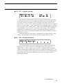
1
YAMAHA
SY85 Music Synthesizer
Owner’s Manual 1
- Getting Started -
The SY85 Music Synthesizer delivers the incredible Yamaha AWM sound
with improved quality and performance power. In addition to superior sound,
the SY85 features “Quick Edit” modes that provide fast, easy access to the
most important voice and performance editing jobs so you can customize the
sound without having to deal with the details. Of course, you still have full
programming power when you want to do some serious voicing. For unmatched
on-stage expression the SY85 also features a sophisticated real-time control
system that lets you modify up to 8 different parameters as you play — in
addition to the traditional pitch and modulation wheels. There’s even a fullfeatured sequencer that allows the SY85 to function as a complete music
workstation. In terms of sound, real-time control, and total production power,
the SY85 offers unprecedented levels of quality and performance.
We urge you to read the owner’s manuals thoroughly in order to realize the
full potential of the SY85 (see “About the Manuals” on page 7), and keep the
manuals in a safe place for future reference.
MAIN FEATURES
● AWM2 Tone Generator System
2nd-generation Advanced Wave Memory (AWM2) technology delivers
dazzling, true-to-life sound with 30-note polyphony.
● Large-capacity Waveform ROM
A large 6-megabyte waveform ROM provides plenty of capacity for topquality samples.
● Expandable Waveform RAM
The SY85 comes supplied with 512 kilobytes of waveform RAM that can
be used to load extra waveforms from a supplied waveform disk or disks from
other sources. Up to 3-megabytes additional RAM can be installed for dramatically increased capacity.
● 256 Voices and 128 Performance Combinations
4 internal memory banks hold 256 individual voices. Voices can be played
individually, or up to four voices can be combined and “layered” to form as
many as 128 performance combinations.
● Advanced Digital Filters
Programmable digital filters allow the SY85 sound to be tailored as required. The filters also feature a resonance parameter equivalent to that found
on the SY77 and SY99.
● Top-quality Effects
The basic quality of the SY85 voices is further enhanced by a range of
programmable effects offering quality rivalling some of the finest separate
signal processing systems — these are essentially the same effects that enhance
the musical impact of the SY99.
● Extensive Real-time Control
In addition to the pitch and modulation wheels, and dual output level controls, the SY85 has 8 slide controls that can be used to control a range of
parameters while performing for unmatched expressive power.
● Easy Editing Interface
8 function keys and slide controls below the large 40-character x 2-line
LCD display allow direct selection and control of the parameters appearing
directly above them in the display for efficient, intuitive editing. A 5x5 mode
selection matrix further enhances operation by allowing fast, easy access to any
of the SY85 modes.
● 9-track 10-song Sequencer
Full-function sequencer with 8 standard tracks and 1 dedicated rhythm
track. Each sequencer “song” has its own 16-part multi-instrument setup.
Rhythm parts can be recorded as “patterns” and then chained to form the complete rhythm track. The SY85 also includes 100 rhythm patterns that you can
simply select and use.
● Other Features
• 3.5” floppy disk drive for versatile data management and storage.
• External memory card slots.
• Quick and in-depth editing modes.
• Function select matrix enhances operating ease.
• 61-key initial and after-touch sensitive keyboard.
• 2 assignable stereo outputs.
1
Contents
Precautions ............................................................................4
About the Manuals
■ The Getting Started Manual (this manual) ................................................................ 7
■ Icons ................................................................................................................................. 8
■ The Feature Reference Manual .................................................................................. 9
The Controls & Connectors
■ Front Panel .................................................................................................................... 10
■ Rear Panel .................................................................................................................... 15
1. Setting Up Your System
■
■
■
■
Connections ................................................................................................................... 17
Power-on Procedure .................................................................................................... 18
Load & Play the Sequencer Demo ............................................................................ 18
Load the Pre-programmed Voice, Performance, & Pattern Data .......................... 20
2. Selecting And Playing Voices
■ Play the Internal Voices .............................................................................................. 21
■ CARD Voice Memory ................................................................................................... 26
■ Real-time Control .......................................................................................................... 27
• PITCH BEND WHEEL .............................................................................................. 27
• MODULATION WHEEL ............................................................................................. 27
• CONTINUOUS SLIDERS .......................................................................................... 28
• FOOT CONTROLLER ............................................................................................... 29
• KEYBOARD AFTERTOUCH..................................................................................... 29
3. The Performance Mode
■
■
■
■
2
Play the Internal Performance Combinations ........................................................... 30
CARD Performance Memory ....................................................................................... 32
Programming Your Own Performance Combinations .............................................. 33
Further Possibilities … ................................................................................................ 39
4. Voice Editing & Effects .................................................40
■ Further Possibilities … ................................................................................................ 46
5. The Sequencer
■ Real-time Recording (Tracks 1 … 8) ........................................................................ 47
■ Step Recording (Tracks 1 … 8) ................................................................................. 52
■ Creating A Rhythm Track ............................................................................................ 55
• LISTEN TO THE INTERNAL PATTERNS .............................................................. 55
• RECORDING AN ORIGINAL PATTERN — REAL TIME ..................................... 56
• RECORDING AN ORIGINAL PATTERN — STEP RECORD .............................. 58
• BUILDING A RHYTHM TRACK ............................................................................... 60
• [F5]: “INS” = Rhythm Track Insert .......................................................................... 62
• [F6]: “DEL” = Rhythm Track Delete ....................................................................... 62
• [F7]: “CPY” = Rhythm Track Copy ......................................................................... 63
• [F8]: “SCH” = Rhythm Track Search ...................................................................... 63
6. Data Management
■ Cards or Disks? ............................................................................................................ 64
• MCD64 RAM Cards .................................................................................................. 64
• Floppy Disks .............................................................................................................. 64
■ Create a Well-organized Data Library ....................................................................... 65
■ Make Separate Performance Disks or Cards ........................................................... 65
■ MIDI Data Recorder Capabilities ................................................................................ 66
INDEX ...................................................................................67
3
Precautions
!! PLEASE READ THIS BEFORE PROCEEDING !!
■ Location
Do not expose the instrument to the following conditions to avoid deformation, discoloration, or more serious damage.
•
•
•
•
•
Direct sunlight (e.g. near a window).
High temperatures (e.g. near a heat source, outside, or in a car during the
daytime).
Excessive humidity.
Excessive dust.
Strong vibration.
■ Power Supply
•
•
•
•
Turn the power switch OFF when the instrument is not in use.
The power supply cord should be unplugged from the AC outlet if the
instrument is not to be used for an extended period of time. (Reconnecting
AC power will re-initialize all settings. As a result, user memory will be
erased.)
Unplug the instrument during electric storms.
Avoid plugging the instrument into the same AC outlet as appliances with
high power consumption, such as electric heaters or ovens. Also avoid using
multi-plug adapters since these can result in reduced sound quality and
possibly damage.
■ Turn Power OFF When Making Connections
•
To avoid damage to the instrument and other devices to which it is connected (a sound system, for example), turn the power switches of all related
devices OFF prior to connecting or disconnecting audio and MIDI cables.
■ MIDI Connections
•
•
When connecting the SY85 to MIDI equipment, be sure to use high-quality
cables made especially for MIDI data transmission.
Avoid MIDI cables longer than about 15 meters. Longer cables can pick up
electrical noise that can causes data errors.
■ Handling and Transport
•
•
•
•
4
Never apply excessive force to the controls, connectors or other parts of the
instrument.
Always unplug cables by gripping the plug firmly, not by pulling on the
cable.
Disconnect all cables before moving the instrument.
Physcal shocks caused by dropping, bumping, or placing heavy objects on
the instrument can result in scratches and more seious damage.
■ Cleaning
•
•
•
•
Clean the cabinet and panel with a dry soft cloth.
A slightly damp cloth may be used to remove stubborn grime and dirt.
Never use cleaners such as alcohol or thinner.
Avoid placing vinyl objects on top of the instrument (vinyl can stick to and
discolor the surface).
■ Electrical Interference
•
This instrument contains digital circuitry and may cause interference if
placed too close to radio or television receivers. If this occurs, move the
instrument further away from the affected equipment.
■ Data Backup
•
•
The SY85 contains a special long-life battery that retains the contents of its
internal voice, performance, song, and non-volatile wave memory even when
the power is turned OFF. The backup battery should last for several years.
When the backup battery needs to be replaced “Change internal battery !”
will appear on the display when the power is turned on. When this happens,
have the backup battery replaced by qualified Yamaha service personnel. DO
NOT ATTEMPT TO REPLACE THE BACKUP BATTERY YOURSELF!
Internal memory data can be corrupted due to incorrect operation. Be sure to
“save” important data to a floppy disk frequently so you have a backup to
revert to if something happens to damage the data in memory. Also note
that magnetic fields can damage data on the disk, so it is advisable to make
a second back-up copy of disks that contain very important data, and keep
backup disks in a safe place away from stray magnetic fields (i.e. away
from speakers, appliances containing motors, etc.).
■ Handle Floppy Disks and the Disk Drive With Care
•
•
•
•
•
•
Use only 3.5” 2DD type floppy disks.
Do not bend or apply pressure to the floppy disk. Do not open the shutter
and touch the surface of the floppy disk inside.
Do not expose the disk to high temperatures. (e.g. direct sunlight)
Do not expose the disk to magnetic fields. Magnetic fields can partially or
totally erase data on the disk, rendering the disk unreadable.
To eject a floppy disk, press the eject button slowly as far as it will go
then, when the disk is fully ejected, remove it by hand.
The disk may not be ejected properly if the eject button is pressed too
quickly, or it is not pressed in as far as it will go (the eject button may
become stuck in a half-pressed position and the disk extends from the drive
slot by only a few millimeters). If this happens, do not attempt to pull out
the partially ejected disk. Using force in this situation can damage the diskdrive mechanism or the floppy disk. To remove a partially ejected disk, try
pressing the eject button once again, or push the disk back into the slot and
then repeat the eject procedure carefully.
Do not insert anything but floppy disks into the disk drive. Other objects
may cause damage to the disk drive or the floppy disk.
5
■ Data Card and Wave Card
•
Never attempt to force a voice card into the waveform slot, or vice versa.
Doing so can cause serious damage to the card connectors.
■ Service and Modification
•
The SY85 contains no user serviceable parts. Opening it or tampering with
it in anyway can lead to irreparable damage and possibly electric shock.
Refer all servicing to qualified YAMAHA personnel.
■ Third-party Software
•
Yamaha can not take any responsibility for software produced for this product by third-party manufacturers. Please direct any questions or comments
about such software to the manufacturer or their agents.
YAMAHA is not responsible for damage caused by improper handling
or operation.
6
About the Manuals
The SY85 comes with two manuals — Getting Started and Feature Reference.
■ The Getting Started Manual (this manual)
In addition to an overview of the SY85 controls and connectors (page 10),
the Getting Started manual contains six chapters that take you through the
main procedures you will need to know to become familiar with your SY85:
1. Setting Up Your System [Page 17]
Basic system connections, powering up, loading and playing the demo,
and loading the pre-programmed voice and performance data.
2. Selecting And Playing Voices [Page 21]
Selecting and playing voices from the INTERNAL 1, INTERNAL 2 and
CARD memories, and using the real-time controls.
3. The Performance Mode [Page 30]
Selecting and playing performance combinations from the INTERNAL 1,
INTERNAL 2 and CARD memories, and programming original performance combinations.
4. Voice Editing & Effects [Page 40]
Fast, easy voice editing and effect setup using the VOICE QUICK EDIT
mode.
5. The Sequencer [Page 47]
Recording and playing sequences and patterns.
6. Data Management [Page 64]
Some ideas on how to efficiently manage your SY85 data.
We recommend that you go through the tutorials in sequence while actually
carrying out procedures on your SY85. Once you’ve gone through the entire
TUTORIALS section in this way, you should be familiar enough with the SY85
to need only the Feature Reference manual in future.
7
■ Icons
The following simple icons are used throughout the Getting Started manual
to draw attention to important points and information where necessary. The
icons also make it easier to differentiate between information that you should
read immediately and information that can be skipped until later, hopefully
helping you to become familiar with the SY85 in the quickest, most efficient
manner possible.
CAUTION
This icon warns of possible hardware damage, software malfunction, or any other serious problem that may occur due to
improper operation or set up.
IMPORTANT
This icon marks information that you must read — i.e. important steps or procedures that are essential for proper, efficient,
or easy operation.
DETAIL
HINT
8
The magnifying-glass icon indicates information that may not
be essential for general operation, but is a more detailed
explanation of a feature, a description of the principle involved,
etc. You can skip this information if full details are not required
immediately.
Hints or ideas that are not specifically musical but may make
operation easier or more interesting are marked by the lightbulb icon.
■ The Feature Reference Manual
The Feature Reference manual is the “nuts and bolts” reference for the
SY85, individually describing its many functions in detail. The Feature Reference manual is divided into 7 main sections, each describing the various functions within a particular SY85 edit or utility mode.
1.
2.
3.
4.
5.
6.
7.
Performance Edit Mode ...... [Page
Voice Edit Mode ................... [Page
Drum Voice Edit Mode ........ [Page
Song Edit Mode .................... [Page
Pattern Edit Mode ................ [Page
Utility Mode ............................ [Page
Wave Edit Mode .................... [Page
13]
57]
119]
147]
201]
209]
237]
Once you have become familiar with the way the SY85 works by going
through the Getting Started manual, you should only need to refer to the Feature Reference manual from time to time to get details on functions you’ve
never used before, or refresh your memory about functions that you don’t use
very often.
Each section of the Feature Reference manual has its own table of contents,
so you should be able to locate any particular function quickly and easily.
Functions and references can also be located by referring to the index at the
back of the manual.
9
5 OUTPUT 1 and OUTPUT 2 Controls
Adjust the volume of the sound delivered via the rear-panel OUTPUT1 and
OUTPUT 2 jacks as well as the PHONES jack.
6 SEQUENCER Keys
Control the recording and playback functions of the internal sequencer.
Getting Started: page 51.
7 Liquid Crystal Display Panel
This 40-character x 2-line backlit liquid crystal display panel shows all
essential information for easy operation and programming.
Getting Started: page 21.
8 [F1] through [F8] Function Keys
The functions of these keys depend on the selected mode. They are used to
engage a function indicated on the display immediately above the key, or select
a parameter immediately above the key for editing.
Getting Started: page 19.
Feature Reference: page 10.
9 [CS1] through [CS8] Continuous Sliders
In the voice and performance play modes these controls are used for realtime expressive control. In the edit and utility modes, however, they are used to
edit the parameters that appear immediately above each continuous slider on the
display.
Getting Started: page 28.
Feature Reference: page 10.
0 [SHIFT] Key
The [SHIFT] key is sometimes used to access secondary functions, parameters, or displays. It is also used in conjunction with the [STORE] key to call
the edit compare function.
Getting Started: page 35.
Feature Reference: page 14.
! [STORE] Key
Used to store edited data to an internal or card memory location. It is also
used in conjunction with the [SHIFT] key to call the edit compare function.
Getting Started: page 38.
Feature Reference: page 55.
@ [EF BYPASS] Key & Indicator
This key is used to bypass the SY85’s internal digital effect system, turning
all effects off. Effects are off when the [EF BYPASS] key indicator is lit.
12
# [EXIT/NO] and [ENTER/YES] Keys
The [EXIT/NO] key can generally be used to exit from any sub-mode or
function, while the [ENTER/YES] key is used to engage a variety of sub-modes
and functions. These keys are also used to respond to the “Are you sure?”
confirmation prompt when saving or initializing data.
Getting Started: page 27.
Feature Reference: page 9.
$ [-1] and [+1] Keys
Can be used to select voices, performance combinations, sequencer songs,
and patterns. These keys can also be used to edit parameter values in any of
the SY85 edit modes. Either key can be pressed briefly for single stepping in
the specified direction, or held for continuous scrolling.
Getting Started: page 23.
Feature Reference: page 9.
% Data Entry Dial
The data entry dial provides a fast, efficient way to cover a broad range of
voice or performance numbers when, for example, you’re looking for a voice
but don’t know the voice number. It’s also handy for making large value
changes in any of the edit modes.
Getting Started: page 23.
k l
Feature Reference: page 9, 10.
^ PAGE [ ], [ ], and [MENU] Keys
k
l
In any of the edit and utility modes these keys are used to select the various edit screens. The [ ] and [ ] are used to scroll backward or forward
through the available screens one at a time, while the [MENU] key calls a
menu that allows the desired screen to be directly specified and accessed by
number.
Getting Started: page 19.
Feature Reference: page 8.
& MEMORY [INTERNAL1], [INTERNAL2], & [Card] Keys
Select the memory area — internal 1, internal 2, or card — from which
voices or performance combinations will be selected.
Getting Started: page 21.
Feature Reference: page 14.
* GROUP [A] Through [H] Keys
In addition to their function in selecting voice or performance numbers, the
GROUP keys are used to enter characters for voice, performance, song, and
pattern names. They are also used to enter note lengths when recording with
the internal sequencer.
Getting Started: page 22.
Feature Reference: page 14.
13
( PROGRAM [1] Through [8] Keys
The PROGRAM keys are used in conjunction with the MEMORY and
GROUP keys to select voices and performance combinations. They are also
used to enter characters for voice, performance, song, and pattern names, and
to enter ties, rests, and accents when recording with the internal sequencer.
When editing performance combinations they are also used to select the layer
to be edited, and to mute specific layers as required.
Getting Started: page 22.
Feature Reference: page 14.
) Floppy Disk Drive
The SY85’s built-in floppy disk drive allows easy, economical, high-volume
storage of voice, performance, sequencer, and wave data. The disk-in-use
indicator below the drive slot lights while any disk operation is in progress
(NEVER attempt to remove a disk or turn the power off while a disk operation
is in progress). The eject button, also below the disk slot, is used to remove
disks from the drive.
Getting Started: page 18.
Feature Reference: page 225.
q DATA & WAVEFORM Card Slots
The DATA slot accepts Yamaha MCD64 Memory Cards for storage and
retrieval of SY85 voices and performance combinations. It will also accept preprogrammed ROM voice/performance cards. The WAVEFORM slot accepts preprogrammed ROM cards containing wave data that can be used by the SY85.
The card wave data can be loaded into the SY85’s internal wave RAM
memory.
Getting Started: page 64.
14
Feature Reference: page 250.
y FOOT CONTROLLER Jack
An optional Yamaha FC7 or FC9 foot controller connected here can be
used for amplitude modulation, pitch modulation, frequency modulation,
envelope generator bias, and filter cutoff frequency control.
Getting Started: page 17.
u FOOT VOLUME Jack
An optional Yamaha FC7 or FC9 foot controller connected here can be
used for volume control.
Getting Started: page 17.
i CLICK VOLUME Control
This knob adjusts the volume of the click (metronome) produced by the
sequencer.
Feature Reference: page 217.
o MIDI IN, OUT and THRU Connectors
The MIDI IN connector receives the data from an external sequencer or
other MIDI device which is to control or transmit data to the SY85. The MIDI
THRU connector simply re-transmits the data received at the MIDI IN connector, allowing convenient chaining of MIDI devices. The MIDI OUT connector
transmits data corresponding to all SY85 performance operations, or bulk data
when one of the MIDI data transmission functions are activated.
p Wave RAM Expansion Slots
You can insert extra memory modules into these slots to expand the wave
memory to a maximum of 3 Megabytes.
Feature Reference: page 285.
16
■ Power-on Procedure
Believe it or not, there’s actually a “right” way to turn on a sound system
that will minimize the possibility of damage to the equipment (and your ears!).
1. Make sure your sound system’s volume control and the SY85 volume
controls are turned all the way down prior to turning power on.
2. Turn on the SY85.
3. Turn on the sound system.
4. Raise the sound system volume to a reasonable level.
5. Gradually raise the SY85 OUTPUT1 and OUTPUT2 controls while playing
the keyboard to set the desired listening level.
IMPORTANT
The SY85 automatically transmits MIDI control change data
corresponding to its control status when its power switch is
turned ON or OFF. This can interfere with operation of other
MIDI equipment connected to the SY85 MIDI OUT connector.
If the SY85 is connected to other MIDI equipment, the SY85
power switch should be turned ON first, and turned OFF last.
■ Load & Play the Sequencer Demo
Once you’ve set up your SY85 system, you might like to load and play the
demo sequence provided on the “DEMO” disk.
IMPORTANT
Loading the demo data overwrites the sequencer, wave , and
voice memory, so if you have any important data in either of
these memory areas make sure it is safely stored to disk before
loading the demo data.
1. Insert the DEMO Disk
Insert the DEMO disk into the disk drive. The sliding disk shutter should
go in first, and the label side of the disk should face upward.
2. Select the Utility DISK ALL LOAD Function
Press the [UTILITY] button so that its indicator lights, then press the SUB
MODE [DISK] key (the lowest SUB MODE key). A display with the word
“DISK” in the upper left corner should appear.
DISK`All```````<--NEW--*>```````````````
[LOAD]SAVE```````Disk=01``¥`Internal````
18
1. Setting Up Your System
k
If necessary, press the PAGE [ ] key a few times until the “DISK ALL”
display shown above appears. Also press the [F1] key to make sure that the
LOAD function is selected (the square brackets should appear around “LOAD”
on the display).
3. Load the Demo Data
Press the [ENTER/YES] once. “Are you sure?” will appear on the display.
Press [ENTER/YES] a second time to actually begin loading the data.
DISK`All```````<--NEW--*>```````````````
```````**`BUSY`**`Now`executing`!```````
“** BUSY ** Now executing !” will appear on the display while the data
is being loaded.
4. Engage the SONG Mode
When the data has finished loading, press the [SONG] key to engage the
song mode.
SONG`PLAY``````Meas`Tempo`Time`````(TR1)
`01:Demo````````001``120``4/`4`````[Tch]
5. Play the Demo
Press the SEQUENCER [RUN] key to play the demo sequence. You can
stop playback at any time by pressing the [STOP] key.
6. Eject the Disk
Press the eject button, below the disk drive slot, to eject the DEMO disk,
then store the disk in a safe place.
1. Setting Up Your System
19
■ Load the Pre-programmed Voice, Performance, & Pattern
Data
Although the factory pre-programmed voices, performance combinations,
and patterns are stored in the SY85 internal memory when the instrument is
initially shipped, there is always a possibility that all or part of the memory has
been erased or modified by the time the instrument gets to you. Here’s how
you can re-load all the pre-programmed data.
IMPORTANT
Loading the pre-programmed data overwrites any other data
that is in the SY85 internal memory, so if you have any
important data in memory make sure it is safely stored to disk
before loading the demo data.
1. Insert the DATA Disk
Insert the DATA disk into the disk drive. The sliding disk shutter should go
in first, and the label side of the disk should face upward.
2. Select the Utility DISK ALL LOAD Function
Press the [UTILITY] button so that its indicator lights, then press the SUB
MODE [DISK] key (the lowest SUB MODE key). A display with the word
“DISK” in the upper left corner should appear.
DISK`All```````<--NEW--*>```````````````
[LOAD]SAVE```````Disk=01``¥`Internal````
k
If necessary, press the PAGE [ ] key a few times until the “DISK ALL”
display shown above appears. Also press the [F1] key to make sure that the
LOAD function is selected (the square brackets should appear around “LOAD”
on the display).
3. Load the Data
Press the [ENTER/YES] once. “Are you sure?” will appear on the display.
Press [ENTER/YES] a second time to actually begin loading the data.
DISK`All```````<--NEW--*>```````````````
```````**`BUSY`**`Now`executing`!```````
“** BUSY ** Now executing !” will appear on the display while the data
is being loaded.
4. Eject the Disk
When the data has finished loading press the eject button, below the disk
drive slot, to eject the DATA disk, then store the disk in a safe place.
20
1. Setting Up Your System
■ Internal Voice List
● INTERNAL VOICE 1
No.
A1
A2
A3
A4
A5
A6
A7
A8
B1
B2
B3
B4
B5
B6
B7
B8
C1
C2
C3
C4
C5
C6
C7
C8
D1
D2
D3
D4
D5
D6
D7
D8
24
Voice Name
SP
SP
SP
SP
SP
SP
SP
SP
AP
AP
AP
AP
AP
AP
KY
KY
BA
BA
BA
BA
BA
BA
BA
BA
ST
ST
ST
ST
ST
ST
ST
ST
Makro
Movie
SawSt
Poly
Sweet
Phaze
Abyss
Glass
Grand
Rock
Tack
Chors
Dance
Touch
EP1
EP2
Wood
Pitz
Fingr
Pick1
Pick2
Frtls
Thump
Slap
Power
Sectn
Arco
Pizz
Deep
Sfz
Violn
JeanL
● INTERNAL VOICE 2
No.
E1
E2
E3
E4
E5
E6
E7
E8
F1
F2
F3
F4
F5
F6
F7
F8
G1
G2
G3
G4
G5
G6
G7
G8
H1
H2
H3
H4
H5
H6
H7
H8
Voice Name
SC
SC
SC
SC
SC
SC
SC
SC
BR
BR
BR
BR
BR
BR
BR
BR
GT
GT
GT
GT
GT
GT
GT
GT
ME
ME
ME
ME
ME
ME
ME
DR
Wondr
Ecko
Perc
Clav
Fingr
SPike
Housy
Pan
Trump
Mute
Tromb
Horn
Tuba
TpSfz
EnsSF
TpEns
Steel
Dark
Nylon
12Str
Strt1
Strt2
Mute
Comp1
Mello
Orch1
Orch2
Kali
Hand
Tink
OrchR
PTN
2. Selecting And Playing Voices
No.
A1
A2
A3
A4
A5
A6
A7
A8
B1
B2
B3
B4
B5
B6
B7
B8
C1
C2
C3
C4
C5
C6
C7
C8
D1
D2
D3
D4
D5
D6
D7
D8
Voice Name
SP
SP
SP
SP
SP
SP
SP
SP
KY
KY
KY
KY
KY
KY
KY
KY
BA
BA
BA
BA
BA
BA
BA
BA
ST
ST
ST
ST
ST
ST
ST
ST
Sweep
Space
Nasty
Smoky
Goner
Vizon
Slow
Sqare
EP3
EP4
EP5
EP6
EP7
EP8
EP9
EP10
Syn1
Syn2
Syn3
Syn4
Syn5
Syn6
Syn7
Syn8
Sizzl
Brite
Thin
Dark
Synth
Anlog
Combo
Tron
No.
E1
E2
E3
E4
E5
E6
E7
E8
F1
F2
F3
F4
F5
F6
F7
F8
G1
G2
G3
G4
G5
G6
G7
G8
H1
H2
H3
H4
H5
H6
H7
H8
Voice Name
SC
SC
SC
SC
SC
SC
SC
SC
BR
BR
BR
BR
BR
BR
BR
BR
GT
GT
GT
GT
GT
GT
GT
GT
ME
ME
ME
ME
ME
ME
ME
DR
Jrney
Mute
Metal
Vox
Aha!
Topia
Wires
Vocal
Tpts
Stab
Toto
Rezz
Saw
SawSF
Wow
Swell
Harm
Strt3
Dist
Warm
Comp2
Wah
Feed
Jazz
Voics
Tomi
Soro
Grind
Gizmo
Bottl
Templ
Zones
● INTERNAL VOICE 3
No.
A1
A2
A3
A4
A5
A6
A7
A8
B1
B2
B3
B4
B5
B6
B7
B8
C1
C2
C3
C4
C5
C6
C7
C8
D1
D2
D3
D4
D5
D6
D7
D8
Voice Name
SP
SP
SP
SP
SP
SP
SP
SP
KY
KY
KY
KY
KY
KY
KY
KY
BA
BA
BA
BA
SL
SL
SL
SL
TP
TP
TP
TP
TP
TP
TP
TP
Paddy
Nehan
Wine
Hyper
Big
Exita
Freqs
Mello
EP11
EP12
Clav1
Clav2
Hrpsi
Acrdn
Cali1
Cali2
Syn9
Syn10
Syn11
Syn12
Digi
Lead
Saw1
Saw2
Timp
Glock
Hands
Mrmba
Steel
Tubal
Vibes
Xylo
● INTERNAL VOICE 4
No.
E1
E2
E3
E4
E5
E6
E7
E8
F1
F2
F3
F4
F5
F6
F7
F8
G1
G2
G3
G4
G5
G6
G7
G8
H1
H2
H3
H4
H5
H6
H7
H8
Voice Name
SC Synnr
SC Digi1
SC Bari
SC Sqiff
SC Bell
SC Digi2
SC Rezz
SC Digi3
BR Syn1
BR Syn2
BR Syn3
BR Syn4
WN Tenor
WN Alto
WN Sopr
WN Bari
SE Rain
SE Star
SE BDup
SE Templ
MI Ride
SE Alert
BR East
BR Tooth
SE Indus
SE Chou
SE Demon
SE Dropr
SE Wind
SE Rezo
SE Noize
DR GMIDI
No.
A1
A2
A3
A4
A5
A6
A7
A8
B1
B2
B3
B4
B5
B6
B7
B8
C1
C2
C3
C4
C5
C6
C7
C8
D1
D2
D3
D4
D5
D6
D7
D8
Voice Name
CH Aah
CH Ooh
CH Ghost
CH Vespa
CH Vocod
CH Pure
CH Quire
CH Breth
OR JazB
OR Perc
OR Smoke
OR Dist
OR Cheap
OR Click
OR Pipes
OR Airy
SL Squar
SL Sync
SL Cutty
SL Hamma
SL Pulse
SL Dist
SL Lyle
SL Whisl
TP SynDr
TP Loggy
TP Angle
TP Bambu
TP Syn
TP Siam
TP Tinkl
TP Agone
No.
E1
E2
E3
E4
E5
E6
E7
E8
F1
F2
F3
F4
F5
F6
F7
F8
G1
G2
G3
G4
G5
G6
G7
G8
H1
H2
H3
H4
H5
H6
H7
H8
Voice Name
FI Blue1
FI Kalim
FI Sitar
FI Harp
FI DulcM
FI DulcD
FI Dudel
FI Blue2
WN Pan
WN Clari
WN Basso
WN Oboe
WN Picc
WN Recor
WN Flute
WN Breth
FI Lip
WN SaxSF
SE Heli
MW EGBia
AT EGBia
MI EPNP
MI Hiss
MI Crash
SE Gobln
SE Up&Up
SE S&H
SE Hyena
SE It
SE Hell
SE Pops
DR Efect
2. Selecting And Playing Voices
25
Note that the voices are arranged in categories for easier access. The category of each voice is identified by a two-character prefix, as follows:
AP ............... Acoustic Piano
OR ............... Organ
KY ............... Keyboard
BR ............... Brass
ST ................ Strings
BA ............... Bass
GT ............... Guitar
WN .............. Wind
FI ................. Folk Instrument
CH ............... Chorus
TP ................ Tuned Percussion
SP ............... Synth Pad
SC ............... Synth Comp
SL ................ Synth Lead
ME ............... Musical Effect
SE ............... Sound Effect
DR ............... Drums
MI ................ Miscellaneous Instrument
AT ............... After Touch
MW .............. Modulation Wheel
A more detailed voice list is provided in the Feature Reference manual
appendix (page 306 through 309).
HINT
If you don’t get any sound at this point: Make sure your sound
system is turned ON and the volume is turned up to a
reasonable level, make sure that the SY85 OUTPUT 1 and
OUTPUT 2 controls are turned up to a reasonable level, and
check all connections carefully.
■ CARD Voice Memory
The CARD memory is an optional Yamaha MCD64 Memory Card (or preprogrammed voice card) plugged into the SY85 DATA slot. Memory cards are
convenient for external storage and transportation of voices you or others
create. You can also store sets of related voices on different memory cards. An
MCD64 Memory Card holds four banks of 64 voices each — a total of 256
voices per card.
CARD voice numbers are preceded by the letter “C”. The four voice banks
are selected in sequence by repeatedly pressing the [CARD] key:
… CI → CII → C III → CIV → C I …
Individual voices are then selected by using the GROUP and PROGRAM
keys (or the [-1]/[+1] keys or data dial) in exactly the same way as the INTERNAL voices.
26
2. Selecting And Playing Voices
IMPORTANT
A properly formatted Yamaha MCD64 memory card (or an
appropriate pre-programmed voice card) must be inserted in
the CARD slot before the CARD memory can be selected. If no
memory card is present, the “Data Card not ready!” display will
appear when you attempt to select the card voice memory. If
this happens, press the [EXIT/NO] key to return to the voice play
mode.
■ Real-time Control
The SY85 provides a number of controllers that can be used for real-time
musical control. Some, such as the pitch bend wheel, have a fixed function,
while others can be set to control a wide range of parameters including amplitude and pitch modulation, filter modulation, and direct control of effect parameters.
Each voice has its own completely independent set of controller assignments, so any assignments you make using the appropriate VOICE EDIT mode
functions (described in the Features Reference manual) will apply only to the
current voice.
● PITCH BEND WHEEL
Rolling the PITCH wheel upward (away from you) will raise the pitch of
notes played on the keyboard, while rolling the wheel in the opposite direction
will lower the pitch. The PITCH wheel is self-centering and will always return
to center position (normal pitch) when released.
DETAIL
The maximum range of the PITCH wheel can be set using the
PITCH function described on page 82 of the Feature Reference
manual.
● MODULATION WHEEL
Rolling the MODULATION wheel upward (away from you) will increase
the depth of the type of modulation set for the currently selected voice. The
MODULATION wheel stays wherever it is set, so you can set it and leave it at
any position that produces the desired modulation effect.
DETAIL
The MODULATION wheel can control pitch, amplitude, and
frequency modulation, as well as envelope generator bias and
filter cutoff frequency. The type of control applied can be
independently programmed for each voice using the parameters
described on page 83 of the Feature Reference manual.
2. Selecting And Playing Voices
27
● FOOT CONTROLLER
An optional Yamaha FC7 or FC9 Foot Controller plugged into the rearpanel FOOT CONTROLLER jack can be assigned to amplitude modulation,
pitch modulation, frequency modulation, envelope generator bias depth, and
filter cutoff frequency depth control via the VOICE EDIT mode FOOT CONTROLLER DEPTH functions described on page 85 of the Feature Reference
manual.
● KEYBOARD AFTERTOUCH
Keyboard aftertouch response is most frequently used for vibrato control:
the harder you press the keys the more vibrato is applied. This makes it possible to control vibrato without having to remove one hand from the keyboard to
use the MODULATION wheel. For the same reason, aftertouch is also often
used for pitch control. Many of the internal voices provided with the SY85
have preset aftertouch functions (see the voice list on page 306 through 309),
but you can assign aftertouch to a number of different functions by using the
VOICE EDIT mode AFTER TOUCH DEPTH functions described on page 87 of
the Feature Reference manual.
2. Selecting And Playing Voices
29
3. The Performance Mode
The SY85 PERFORMANCE mode makes it possible to combine up to four
voices in “performance combinations” that significantly enhance the instrument’s performance capabilities. 128 performance combinations can be stored in
internal memory and recalled in the same way as the voices. Before we look at
how you can create your own performance combinations, try selecting and
playing some of the combinations provided with the SY85.
■ Play the Internal Performance Combinations
The SY85 can access three different performance memories — INTERNAL
1, INTERNAL 2, and CARD.
1. Select the Performance Mode
Press the [PERFORMANCE] key so that its indicator lights and the words
“PERFORMANCE PLAY” appear on the top line of the LCD panel.
PERFORMANCE`PLAY``````````¡A1:CO`Dream``
`Parallel`EF1:EQ`->`Rev1`EF2:Cho`&`Rev``
DETAIL
The information displayed on the bottom display line tells you
about the current effect mode and what effects are assigned to
the SY85’s two effect processors. See the “Effects” section
beginning on page 254 of the Feature Reference manual for
more details.
2. Select an Internal Performance Memory
In the PERFORMANCE mode each INTERNAL memory key accesses a
single bank of 64 performance combinations.
[INTERNAL 1]
I I .................. Internal performance bank 1.
[INTERNAL 2]
I II .................. Internal performance bank 2.
3. Select a Performance Combination
After selecting an internal performance bank, you can select any of the 64
performance combinations it contains in exactly the same way as you select
voices. See page 21 for voice selection details.
30
3. The Performance Mode
4. Play
Try playing the selected performance combination on the keyboard. In some
cases you’ll hear several voices “layered” on top of one another, in others
you’ll get a split keyboard effect with one voice on the left-hand side of the
keyboard and another on the right. Select a number of different performance
combinations and try them out. Here’s an abbreviated performance list for easy
reference.
■ Internal Performance List
● INTERNAL PERFORMANCE 1
No.
A1
A2
A3
A4
A5
A6
A7
A8
B1
B2
B3
B4
B5
B6
B7
B8
C1
C2
C3
C4
C5
C6
C7
C8
D1
D2
D3
D4
D5
D6
D7
D8
Voice Name
CO Dream
KY Piano
SP Aztec
SC Wyrz
CH Choir
BA Pick1
ST Rosin
BR Stab
CO Soire
OR Bee
SP Lush
SC Rude
CH Breth
BA Swap
ST Octvs
BR Pro5
CO Orch
KY Digi1
SP Faery
SC Talk
CH OohAh
BA Pick2
ST Pitz
BR Sfz
CO Sable
KY Roady
SP Slide
SC Klav
CH Vespa
BA -Fret
ST Rings
BR Forte
No.
E1
E2
E3
E4
E5
E6
E7
E8
F1
F2
F3
F4
F5
F6
F7
F8
G1
G2
G3
G4
G5
G6
G7
G8
H1
H2
H3
H4
H5
H6
H7
H8
● INTERNAL PERFORMANCE 2
Voice Name
CO Jazzr
OR Gimme
SP Lite
SC Buzz
CH Munch
BA Rezzo
ST Dark
BR Saw
CO E.S.P
KY Elek
SP Stars
SC Snaps
CH Abyss
BA Mini
ST 2002
BR Obie
CO Pnooh
OR Nave
SP Ace
SC Point
CH Comet
BA Guppy
ST Big
BR Fatti
CO Inca
KY Funky
SP Vekta
SC Pizza
CH Oral
BA Doom
ST Tron
BR Swell
No.
A1
A2
A3
A4
A5
A6
A7
A8
B1
B2
B3
B4
B5
B6
B7
B8
C1
C2
C3
C4
C5
C6
C7
C8
D1
D2
D3
D4
D5
D6
D7
D8
Voice Name
CO Ncert
KY Loud
SP Carol
SL Mitey
ME Orion
GT Amped
SE Rolls
WN Tenor
CO DXStr
OR Sine
SP Venus
SL Chick
ME Glitz
GT Strat
SE C-tar
WN Sacks
CO Stass
KY Digi2
SP Whino
SL L7
ME Honto
GT Phunk
SE Xeno
WN Alto
CO Megin
KY Jerry
SP Hinx
SL Eazy
ME Mars
GT Rock
SE Storm
WN Panic
No.
E1
E2
E3
E4
E5
E6
E7
E8
F1
F2
F3
F4
F5
F6
F7
F8
G1
G2
G3
G4
G5
G6
G7
G8
H1
H2
H3
H4
H5
H6
H7
H8
Voice Name
CO Gospl
OR Cheap
SP Pluto
SC Clank
ME Ecko
GT Harm
SE Zoom
BR Reeds
CO Ethos
KY PnoMW
SP Synth
FI Santo
ME Alien
GT El12
SE Delay
BR Lips
CO Kings
KY Calio
SP Anlog
SC Wind
ME Spark
GT 12Str
SE Flies
BR Miles
CO Happi
KY Digi3
SP Arpeg
TP Bells
ME Hit
GT Acstc
SE Hero
BR Fanfr
* In addition to the voice categories described on page 26, the performance mode has a “CO” (combination)
category.
3. The Performance Mode
31
■ CARD Performance Memory
Any Yamaha MCD64 Memory Card used for voice storage can be used for
performance storage as well. An MCD64 Memory Card holds two banks of 64
performance combinations each — a total of 128 performance combinations in
addition to 256 voices per card.
CARD performance numbers are preceded by the letter “C”. The two performance banks are selected in sequence by repeatedly pressing the [CARD]
key:
… CI → CII → C I …
Individual performance combinations are then selected by using the GROUP
and PROGRAM keys (or the [-1]/[+1] keys or data dial) in exactly the same
way as the INTERNAL voices and performance combinations.
IMPORTANT
32
3. The Performance Mode
A properly formatted Yamaha MCD64 memory card (or an
appropriate pre-programmed voice card) must be inserted in
the CARD slot before the CARD memory can be selected. If no
memory card is present, the “Data Card not ready!” display will
appear when you attempt to select the card memory. If this
happens, press the [EXIT/NO] key to return to the performance
play mode.
Respond to “Are you sure?” on the display by pressing the [ENTER/YES]
key again. “Completed” will appear for a few seconds when the initialization
job has finished.
PERFORMANCE`JOB`Initialize``````````````
```Completed`!```````````[EDIT]`LYR`````
3. Select the Performance Edit “LAYER” Mode
k
l
Press the SUB MODE [EDIT] key. This selects the performance edit mode.
Use the PAGE [ ] and [ ] keys to select the “LAYER” entry screen (if it
doesn’t appear immediately).
LAYER```````````````````````````````````
`````````````````````````````Hit`[ENTER]
When you’ve located this screen, press [ENTER/YES] to engage the performance edit LAYER mode.
4. Select the Voices for Each Layer
k
If the “LAYER Voice Number” display doesn’t appear as soon as you
engage the performance edit mode, press the PAGE [ ] key a few times until
it does appear (see the “HINT”, below).
LAYER`Voice`Number````````<SP`Makro>ABCD
````A=¡A1`````B=¡A1`````C=¡A1`````D=¡A1`
The voice numbers assigned to each layer are shown across the bottom of
the display. After initialization, voice “IIA1” is assigned to all four layers.
Press the [F2] function key to place the underline cursor under the layer-A
voice number (note that the voice name is shown between parentheses in the
upper right corner of the display), then use the [CS2] control slider or any of
the voice selection methods already described to select voice number “IIC1”
(BA Wood).
Next press the [F4] function key to select the layer-B voice number, and
use the [CS4] control slider or any other voice selection method to select voice
number “IIB1” (AP Grand).
Next press the [F6] function key to select the layer-C voice number, and
use the [CS6] control slider or any other voice selection method to select voice
number “IID1” (ST Power).
Finally, press the [F8] function key to select the layer-D voice number and,
while holding the [SHIFT] key, press the [-1] key to turn layer-D “off”.
3. The Performance Mode
35
LAYER`Voice`Number````````<-------->ABC````A=¡C1`````B=¡B1`````C=¡D1`````D=off`
k
HINT
l
The PAGE [ ] and [ ] keys can usually be used to select the
various parameter and function screens in any edit mode. There
is another way, however, that can be more direct is some cases.
To call the “LAYER Voice Number screen”, for example, press
the [MENU] key, use either the data entry dial or the [-1] and
[+1] keys to select “1:Voice Number”, and then press [ENTER/
YES].
5. Set the Volume of Each Layer
Press the PAGE [
l] key to move to the “LAYER Volume” screen.
LAYER`Volume``````````````<-------->ABC``````127ƒ``````127ƒ```````98∂ ``````---You can now use the [CS2] slider to adjust the volume of the layer-A
voice, the [CS4] slider to adjust the volume of the layer-B voice, and the [CS6]
slider to adjust the volume of the layer-C voice. The volume range is from “0”
to “127”, with “127” being maximum volume. The bars to the right of the
volume parameters indicate volume level — the longer the bar the higher the
volume.
For now, just use [CS6] to lower the volume of the layer-C strings voice to
“98”. Notice that since layer D is turned “off”, no parameter appears for the
layer-D voice.
HINT
In addition to using the control sliders, these and most other
parameters can be adjusted by first pressing the function key
immediately below the parameter in order to select that parameter (the underline cursor will appear below the selected
parameter), and then using either the data entry dial for large
changes or the [-1] and [+1] keys for small stepwise changes.
6. Set the Pan Position of Each Layer
Press the PAGE [
l] key to move to the “LAYER Pan” screen.
LAYER`Pan`L¯¯Æ¯¯R`````````<-------->ABC```````+0```````-15```````+15```````---`
Use the [CS4] slider to set the layer-B pan parameter to “-15 and [CS6] to
set the layer-C pan parameter to “+15”. This pans the piano voice slightly to
the left and the strings voice slightly to the right for a broader, more spacious
sound (the bass voice is left in the center — “+0”). Note the position of the
marker in the graphic pan display on the upper display line as you set these
parameters.
36
3. The Performance Mode
7. Tune Each Layer
Press the PAGE [
l] key to move to the “LAYER Tune” screen.
LAYER`Tune`)NtShft(```````<-------->ABC`+12```+0```+0```+0```+0```+0``---```--`
Since the bass voice we have selected will sound too low if played only on
the lower two octaves of the keyboard, we’ll shift its pitch up one octave. Use
the [CS1] slider to set the layer-A “NtShft” (Note Shift) parameter to “+12”.
8. Set the Note Limits for Each Layer
Press the PAGE [
l] key to move to the “LAYER Note Limit” screen.
LAYER`NoteLimit`)Lo(``````<-------->ABC``C≥ `ø`B2```C3`ø`G8```C3`ø`G8``---`ø---`
Although the note limit parameters can be adjusted via the appropriate
control sliders or other data entry controls, there is an easier way. Press [F2] to
select the upper note limit for the layer-A voice then, while holding the
[SHIFT] key, press the B2 key on the keyboard. Now press [F3] to select the
layer-B lower note limit and, while holding [SHIFT], press the C3 key on the
keyboard. Using the same technique, set the layer-C lower note limit to C3.
DETAIL
Although the current layer-A lower limit (C-2) as well as the
layer-B and layer-C upper limits (G8) extend beyond the keyboard, these settings won’t adversely affect our performance
combination so we won’t bother to change them.
9. Play
Try playing our new performance combination on the keyboard. You should
hear only the BA Wood voice when playing on the lower two octaves (C1
through B2), and a combination of the AP Grand and ST Power voices when
playing on the upper three octaves (C3 through C6).
The COMPARE Function
The COMPARE function lets you compare the sound of the edited performance combination with that of the original performace combination. To engage
the COMPARE mode, press the [STORE] key while holding the [SHIFT] key.
The [PERFORMANCE] key indicator will flash and you’ll hear the original
pre-edit performance combination when you play on the keyboard.
Press the [EXIT/NO] key to exit from the COMPARE mode and return to
the edited data.
3. The Performance Mode
37
10. Go Back And Customize the Parameters
Now you know what the parameters we’ve just edited do, go back and
modify them to create a performance combination that suits your musical needs
(use the PAGE [ ] and [ ] keys to locate the various edit screens).
k
l
11. Store Your Performance Combination
Once you’re satisfied with the sound of your original performance combination, you can store it to an internal performance memory location as follows:
Press the [STORE] key.
PERFORMANCE`STORE`````LayerA:<BA`Wood`>`
``To``¡A1:CO`Dream```¡C1u`¡B1u`¡D1u`off`
Select the performance memory location to which you want to store your
new performance combination using any standard performance selection procedure (e.g. MEMORY, GROUP, and PROGRAM keys).
PERFORMANCE`STORE`````LayerA:<BA`Wood`>`
``To``™D7:SE`Storm```¡C1u`¡B1u`¡D1u`off`
Press [ENTER/YES].
PERFORMANCE`STORE`````````Are`you`sure`?
``To``™D7:SE`Storm```¡C1u`¡B1u`¡D1u`off`
Press [ENTER/YES] again.
PERFORMANCE`STORE````````````Completed`!
``To``™D7:SE`Storm```¡C1u`¡B1u`¡D1u`off`
“Completed !” will appear briefly when the data has been stored, then the
SY85 will return to the PERFORMANCE PLAY mode.
IMPORTANT
38
3. The Performance Mode
If you return to the PERFORMANCE PLAY mode before storing
the edited performance combination, either by pressing the
[EXIT/NO] key or the [PERFORMANCE] key, an inverse letter “E”
will appear to the right of the performance number, indicated
that it has been edited but not stored. You can call the STORE
function at this point and proceed as described above. If you
select a different performance combination before storing,
however, the edited data will be lost. Also note that any previous
data in the performance memory location you store to will be
overwritten by the new data.
HINT
You can use the PERFORMANCE NAME function described on
page 25 of the Feature Reference manual to give your performance combination an original name before storing it.
■ Further Possibilities …
When you’re ready to explore the many other possibilities the SY85 provides for performance programming, read through the “PERFORMANCE EDIT
MODE” section of the Feature Reference manual (page 13).
3. The Performance Mode
39
4. Voice Editing & Effects
For the programmer who wants to get serious about voice programming, the
SY85 offers an extensive range of parameters that allow extremely fine control.
All parameters are discussed in detail in the Feature Reference manual VOICE
EDIT section (page 57), and we recommend that the dedicated programmer
study the Feature Reference manual carefully before embarking on any major
voicing projects. The SY85’s dual-processor effect system is also quite complex, allowing detailed effect setups to be programmed for each voice. The
effect system is described in detail in the feature Reference manual (page 254).
For now, however, let’s see how you can create a new voice quickly and easily
using the VOICE QUICK EDIT mode.
1. Select a Voice
In the VOICE PLAY mode, select the voice you want to edit using the
normal voice selection procedure.
VOICE`PLAY````````````````¡A1:SP`Makro``
`Serial```EF1:EG`Chorus``EF2:Rev.Hall1``
2. Press [QUICK EDIT]
Press the SUB MODE [QUICK EDIT] key to engage the voice quick edit
mode.
3. Select and Set the WAVE Parameters
k
l
If it doesn’t appear immediately when the QUICK EDIT mode is engaged,
use the PAGE [ ] and [ ] keys to locate the “QED WAVE” screen.
QED`WAVE)Group``````Number``````````````
```````01:Piano`````P001:Piano``````````
These parameters provide a fast, easy way to select a new AWM wave for
the current voice, and automatically set the main amplitude envelope generator
parameters to values that produce good results with the selected wave.
For fast, easy selection of the preset SY85 waves, the “Group” parameter,
edited via [CS2], selects 16 different wave categories or “groups”, each containing a number of waves that can be individually selected by using the
“Number” parameter.
40
4. Voice Editing & Effects
Quick Edit Wave Groups
1: Piano
2: Key
3: Brass
4: Wind
5: Strings
6: A.Guitar
7: E.Guitar
8: Bass
9: Folk
10: Synth
11: Choir
12: TPerc
13: Drum
14: Perc
15: SE
16: Osc
Acoustic pianos.
Other keyboards.
Brass instruments.
Wind instruments.
Strings.
Acoustic guitars.
Electric guitars.
Acoustic & electric bass.
Folk & ethnic instruments.
Synthesizer sounds.
Choir & human voice.
Tuned percussion.
Drums.
Percussion instruments.
Sound effects.
Basic oscillator waveforms.
Once the desired group has been selected, use [CS5] to select the wave to
be used in the current voice. The [INTERNAL 1], [INTERNAL 2], and
[CARD] keys can also be used to select the memory area from which the wave
is to be selected. A complete listing of the internal waves is given in the Feature Reference manual appendix (page 310).
4. Select and Set the Amplitude Envelope Generator Parameters
Use the PAGE [
k] and [l] keys to locate the “QED AEG Type” screen.
QED`AEG)Type`````````Atk``Sus``Rel``Vel`
```1:Piano````````````63```--```27```+3`
Rather than having to set numerous level and rate values via the full-edit
amplitude envelope generator parameters, these parameters let you select from a
range of preset envelope types, and then modify the overall attack, sustain, and
release characteristics as required.
[CS1] selects either the envelope defined by the current amplitude envelope
parameter settings, or one of 21 preset amplitude envelope types for the current
voice. The envelope types are:
4. Voice Editing & Effects
41
Quick Edit Envelope Types
0: -------1: Piano
2: Brass
3: SfzBrass
4: SynBrass
5: StFast
6: StSlw/Pd
7: E.Bass
8: SynBass1
9: SynBass2
10: Organ
11: Guitar
12: Pluck1
13: Pluck2
14: SynPad
15: SynComp
16: Percusiv
17: S.Ideal1
18: S.Ideal2
19: S.Ideal3
20: S.Ideal4
21: Init
Full-edit envelope.
Acoustic piano.
Brass.
Sforzando brass.
Synthesizer brass.
Fast-attack strings.
Slow-attack strings (pad).
Electric bass.
Synthesizer bass 1.
Synthesizer bass 2.
Organ.
Guitar.
Plucked instrument 1.
Plucked instrument 2.
Synthesizer pad.
Synthesizer comping (backing).
Percussive.
Sound envelope 1.
Sound envelope 2.
Sound envelope 3.
Sound envelope 4.
Initialized envelope.
[CS5] sets the attack rate for the selected envelope. “63” produces the
fastest attack, while “0” produces the slowest attack. [CS6] sets the sustain
level for the selected envelope, and [CS7] sets the release rate for the selected
envelope.
[CS8] determines how the output level of the voice changes in response to
velocity changes (e.g. keyboard dynamics). Plus “+” settings produce higher
output level in response to higher velocity values — i.e. the harder a key is
played, the louder the sound. The maximum setting of “+7” produces the maximum level variation in response to velocity changes. Minus “-” settings produce
the opposite effect: lower level in response to higher velocity. A setting of
“+0” results in no level variation.
5. Select and Set the FILTER Parameters
Use the PAGE [
screen.
k] and [l] keys to locate the “QED FILTER Type”
QED`FILTER)Type```````````Coff`Reso`Vel`
`````````````1:VeloSoft```115````0``+27`
42
4. Voice Editing & Effects
Although the SY85 includes a sophisticated digital filter system that can be
precisely controlled via the full-edit parameters, the simplified filter parameters
provided here have been specifically created for fast, efficient filter programming.
[CS3] selects either the filter defined by the current filter parameter settings, or one of 15 preset filter types for the current voice. The filter types are:
Quick Edit Filter Types
0: -------1: VeloSoft
2: VeloWide
3: VeloHard
4: VeloReso
5: SynBass1
6: SynBass2
7: SynBras1
8: SynBras2
9: Sweep
10: SlowAtak
11: LPF_Init
12: HPF_Init
13: BPF_Init
14: BEF_Init
15: Thru
Full-edit filter.
Velocity sensitive, soft response.
Velocity sensitive, wide response.
Velocity sensitive, hard response.
Velocity sensitive, resonant.
Synthesizer bass 1.
Synthesizer bass 2.
Synthesizer brass 1.
Synthesizer brass 2.
Sweep-frequency filter.
Slow-attack filter.
Initialized LPF.
Initialized HPF.
Initialized BPF.
Initialized BEF.
No filter.
[CS6] sets the cutoff frequency of the selected filter (0 … 127). Lower
cutoff values produce a lower cutoff frequency and higher values produce a
higher cutoff frequency. If the “Thru” filter type is selected, no cutoff frequency can be set and “---” appears on the display in place of the parameter.
[CS7] determines the degree of filter resonance (00 … 99). This parameter
has a similar effect to the “resonance” settings on traditional analog synthesizer
filters — i.e. it determines the height of a peak in the filter response at the
cutoff frequency. Higher resonance values produce a higher resonant peak and
reduce the overall bandwidth of the filter, passing a narrow band of frequencies
at the filter’s cutoff. If a filter type other than “LPF” is selected, no resonance
can be produced and “--” appears on the display in place of the parameter.
4. Voice Editing & Effects
43
[CS8] determines how the filter cutoff frequency changes in response to
velocity changes (e.g. keyboard dynamics). The range is from -63 to +63. Plus
“+” settings produce higher cutoff frequencies in response to higher velocity
values — i.e. the harder a key is played, the higher the cutoff frequency. The
maximum setting of “+63” produces the maximum level variation in response to
velocity changes. Minus “-” settings produce the opposite effect: lower cutoff
in response to higher velocity. A setting of “+0” results in no cutoff variation.
6. Select and Set the LFO Parameters
Use the PAGE [
k] and [l] keys to locate the “QED LFO” screen.
QED`LFO)```Type`````Speed`Depth`````````
```````````vibrato````64```64```````````
Here, the main LFO parameters are simplified and concentrated in a single
screen for quick, easy programming.
[CS3] determines whether the LFO will produce vibrato (pitch modulation),
tremolo (amplitude modulation), or wahwah (filter cutoff modulation) effects.
The current LFO parameter settings (page 78) are selected when this parameter
is set to “-------”.
[CS5] sets the speed of the LFO (0 … 99). “0” is the slowest speed setting,
producing an LFO speed of approximately 0 Hertz. The fastest setting of 99
produces an LFO speed of approximately 25 Hertz.
[CS6] sets the maximum amount of amplitude (tremolo), pitch (vibrato), or
filter cutoff (wahwah) modulation that can be applied to the current voice. A
“0” setting produces no modulation while a setting of “127” produces maximum
modulation.
7. Select and Set the EFFECT Type & Balance Parameters
Use the PAGE [
k] and [l] keys to locate the “QED EFFECT” screen.
QED`EFFECT)```Type```````````Wet`Balance
``25:EG`Chorus```01:Rev.Hall1````````50%
The SY85 features a complex, high-performance effect system that can be
programmed easily via the parameters presented here and in the following
screen.
[CS1] selects any of the SY85’s 90 effect types for the EFFECT 1 processor, and [CS4] does the same for the EFFECT 2 processor. See page 254 of the
Feature Reference manual for more details on the SY85 effect system.
[CS8] controls the balance between the direct no-effect sound and the effect
sound. The maximum setting of “100” produces maximum effect depth.
44
4. Voice Editing & Effects
8. Select and Set the Main Effect Parameters
Use the PAGE [
k] and [l] keys to locate the “QED EF PARAM” screen.
QED`EF`PARAM)`<`1:Cho`>``)Mod.Freq`[Hz](
`100`Freq``1.2```70```+0```+0``0.8``100`
This screen provides access to the four main parameters each for the current
selected effect 1 and effect 2. The four effect 1 parameters are edited via [CS1]
through [CS4], while the four effect 2 parameters are edited via [CS5] through
[CS8]. The name of the corresponding effect and parameter are shown on the
upper display line when one of these parameters are edited.
The parameters are different for each effect (refer to page 274 of the Feature Reference manual for details).
9. Play
Try playing your new voice on the keyboard (of course, you can play at
any time while editing to hear how it’s progressing).
The COMPARE Function
The COMPARE function lets you compare the sound of the edited voice
with that of the original voice. To engage the COMPARE mode, press the
[STORE] key while holding the [SHIFT] key. The [VOICE] key indicator
will flash and you’ll hear the original pre-edit voice when you play on the
keyboard.
Press the [EXIT/NO] key to exit from the COMPARE mode and return
to the edited data.
10. Store Your New Voice
Once you’re satisfied with the sound of your original voice, you can store it
to an internal voice memory location as follows:
Press the [STORE] key.
VOICE`STORE``````````To`````````````````
`````````````````````¡A1:SP`Makro```````
Select the voice memory location to which you want to store your new
voice using any standard voice selection procedure (e.g. MEMORY, GROUP,
and PROGRAM keys).
VOICE`STORE``````````To`````````````````
`````````````````````™D7:ST`Combo```````
4. Voice Editing & Effects
45
Press [ENTER/YES].
VOICE`STORE``````````To`````````````````
Are`you`sure`?```````™D7:ST`Combo```````
Press [ENTER/YES] again.
VOICE`STORE``````````To`````````````````
```Completed`!```````™D7:ST`Combo```````
“Completed !” will appear briefly when the data has been stored, then the
SY85 will return to the VOICE PLAY mode.
IMPORTANT
HINT
If you return to the VOICE PLAY mode before storing the edited
voice, either by pressing the [EXIT/NO] key or the [VOICE] key,
an inverse letter “E” will appear to the right of the voice number,
indicated that it has been edited but not stored. You can call
the STORE function at this point and proceed as described
above. If you select a different voice before storing, however,
the edited data will be lost. Also note that any previous data in
the voice memory location you store to will be overwritten by
the new data.
You can use the VOICE NAME function described on page 95
of the Feature Reference manual to give your voice an original
name before storing it.
■ Further Possibilities …
When you’re ready to explore the many other possibilities the SY85 provides for voice programming, read through the “VOICE EDIT MODE” section
of the Feature Reference manual (page 57).
46
4. Voice Editing & Effects
5. The Sequencer
The SY85 sequencer has 8 “normal” tracks and a special rhythm track.
Each of the normal sequencer tracks can control a separate “instrument”. Which
track controls which instrument is determined by the multi-play setup instrument assignments and the sequencer track transmit channel assignments (both
are described below). Normally, sequencer tracks 1 through 8 are assigned to
the correspondingly numbered MIDI transmit channels, so tracks 1 through 8
control the multi-play instruments assigned to MIDI channels 1 through 8,
respectively. Track 9, the rhythm track, plays a sequence of rhythm “patterns”
— any of the 100 preset rhythm patterns provided with the SY85, or original
patterns you record in the PATTERN mode.
The SY85 sequencer can hold up to 10 separate “songs” that can be selected and recorded or played as required. Completed songs can also be saved
to external floppy disks for long-term storage.
There are basically two ways to record using the sequencer — realtime or
step write. Both of these methods are described below.
■ Real-time Recording (Tracks 1 … 8)
Realtime recording allows you to directly record anything you play on the
keyboard, capturing the spontaneous timing, keyboard dynamics and controller
operations of the performance. Using the realtime recording mode is, in fact,
very much like using a conventional tape recorder. Realtime recording is best
for parts you can play easily on the keyboard, and for passages in which you
want to retain the human “feel” of naturally varying timing and other musical
factors.
1. Engage the Song Mode and Select a Song Number
Press the [SONG] key to engage the song mode.
SONG`PLAY``````Meas``Tempo`Time````(TR1)
`02:InitSong````001```120``4/`4````[Tch]
The SY85 can hold up to 10 different “songs” in memory at the same time.
Use [CS1] to select a song number from 1 to 10. If this is the first song
you’ve recorded, “1” is a logical choice.
Optional
Set the Transmit Channel For Each Track.
This step is only necessary if you want to change the default track
transmit channel settings: tracks 1 through 8 normally transmit on MIDI
channels 1 through 8, respectively.
Press [F8] to call the Track Transmit Channel display.
Track`Transmit`Channel``````````````````
```1````2````3````4````5````6````7````8`
5. The Sequencer
47
Here you can specify which MIDI channel (1 … 16) each of the
sequencer’s 8 main tracks will transmit on. Functions keys [F1] through [F8]
correspond to tracks 1 through 8. Press a function key to move the underline
cursor to the MIDI channel parameter for that track, then use the corresponding
control slider (e.g. [CS3] for track 3) to set the MIDI transmit channel for that
track. The MIDI transmit channel for the rhythm track (track 9) can be set by
holding the [SHIFT] key and using the [CS8] control slider (note that “RH9”
appears above [CS8] while the [SHIFT] key is held) . The rhythm track is
normally set to transmit on channel 16.
DETAIL
This function is obviously important if you will be using the
SY85 sequencer to drive an external tone generator that has
specific channel requirements.
2. Program the MULTI Setup For the Selected Song
Each SY85 “song” has an independent “multi setup” that can have up to 16
voices assigned to “instruments” 1 through 16. Each instrument is controlled
via the correspondingly numbered MIDI channel.
Press the SUB MODE [MULTI EDIT] key, and then use the PAGE [k ]
and [l ] keys to locate the “MULTI Voice Select” screen shown below. This
screen lets you select the voices that are to be played via the various multisetup channels.
MULTI`Voice`Select`1-`8```````<SP`Makro>
P¡A1`P¡A1`P¡A1`P¡A1`P¡A1`P¡A1`P¡A1`P¡A1`
Only eight voice numbers are shown on the display at one time. Use the
PAGE [k ] and [l ] keys while holding the [SHIFT] key to switch between
multi instruments “1 … 8” and “9 … 16”. The currenty selected group of
voices is indicated on the upper display line.
After moving the cursor to the instrument you want to edit by pressing the
appropriate function key, use the same function key to toggle between PERFORMANCE or VOICE memory (“P” or “V” at the beginning of the voice
number). Then use the [INTERNAL 1], [INTERNAL 2], and [CARD] keys to
select the memory area from which the voice is to be selected, and finally the
GROUP and PROGRAM keys to select the voice. Voices within the selected
memory bank can also be selected directy for each channel by the appropriate
CS sliders. Internal and card voices cannot be mixed.
The voices can individually turned on or off by using the [-] (off) and [+]
(on) keys while holding the [SHIFT] key.
The name of the currently selected voice is shown in the upper right corner
of the display.
DETAIL
48
5. The Sequencer
To make locating voices for multi assignment faster and easier,
a “voice search” function can be accessed from the “MULTI
Voice Select” screen by pressing the SUB MODE [COPY] key.
● STEP
The STEP record mode will be described in “STEP RECORDING”
beginning on page 52.
● PUNC (Real-time Punch-in)
Punch-in recording makes it possible to re-record (replace) a section of a
previously-recorded track without affecting the data before and after the
punch-in section. All operations are the same as for replace recording,
except that you must specify the measure numbers for the beginning and
end of the punch-in segment. If you select “punc” instead of “over” or
“repl,” (see step 3, above) the display will appear as follows:
SONG`RECORD````Meas`Tempo`Time`--------`
PUNC``001ø`001``001``120``4/`4``````````
Use the [CS2] and [CS3] control sliders to set the punch-in and punchout measures, respectively, prior to recording. Other parameters within this
display can be set in the same way as for replace or overdub recording.
Once recording is started the sequence will play back until the punch-in
point is reached, then the replace record mode will be activated until the
punch-out point is reached, allowing you to record the new material. If
recorded material exists following the punch-out point, playback will continue until the end of the sequence.
3-4
Set the Record Tempo.
Use [CS5] to set the tempo you want to record at (shown in beats per
minute on the display). The tempo can be set from 30 to 240 beats per
minute.
3-5
Set the Time Signature.
Use [CS6] to set the time signature of the song to be recorded. The time
signature can only be set if the song selected for recording is “clear” and
does not contain any previous data. See “CLEAR SONG” on page 179 of
the Feature Reference manual for instructions on how to clear one or all
songs.
Optional
Set the Start Measure.
Before actually begin recording you can use the [CS4] slider to set the
measure from which you want to start recording, if the track being recorded
already contains recorded material.
50
5. The Sequencer
7. Record the Next Part
When you’re satisfied that the first track is OK, go back to step 3-2 and
select a new record track, then record. Continue this process until your composition is complete. For difficult tracks you might want to use the step record
mode, described below.
■ Step Recording (Tracks 1 … 8)
Step recording allows you to input parts note by note, rest by rest, without
having to actually play the part on the keyboard. This is ideal for entering
difficult parts from written music, or for extremely complex or fast passages
that would be impossible to play in real time.
1. Select the “Step” Record Mode
The sequencer record mode is entered in the same was as described in the
“REALTIME RECORDING” section, above. Instead of choosing the “repl” or
“over” record mode, select “step.” You can also select a time signature at this
point if nothing has been recorded yet.
2. Press [RUN]
Press the [RUN] key to call the step record display.
Measure & beat number. A
measure and beat number display
of “M004-03,” for example, would
mean “fourth measure, third beat.”
The measure and beat number
correspond to the position of the
cursor under the step write input
display line.
Step write input display line. Each dash
represents a 32nd beat. Plus signs mark the
beginning of each beat specified by the
selected time signature. The example below
corresponds to a 1/4 ... 4/4 time signature. If
an 8-beat time signature (1/8 ... 8/8) were
selected, plus signs would appear every 4
32nd beats. The cursor is placed under the
appropriate beat of the display line by using
the data entry dial. The position of the cursor is
also reflected by the measure and beat number
displays to the left.
M001-01Ú-------+-------+-------+-------Ú
``0``Gate=NORM`Vel=norm[ERASE][PGM]=P¡A1
Note length to be entered. A “0”
indicates that no note will be
entered. Standard note lengths
from 32nd to whole notes,
including dotted versions, are
displayed in this position in
standard written form. Others are
displayed as numbers.
52
5. The Sequencer
Gate time. Select “STAC”
(staccato), “NORM” or “SLUR”
by repeatedly pressing the [F3]
function key.
“STAC” = 50% gate time.
“NORM” = 80% gate time.
“SLUR” = 99% gate time.
Sets the note velocity
value to “norm”, “acc1”,
“acc2”, “acc3”, or “fix/
kbd”. These values can
be independently
assigned in the utility
mode.
3. Set the Gate Time and Velocity
Use the [F3] function key to select the gate time of the first note to be
entered: “STAC” for short, staccato notes; “NORM” for normal-length notes; or
“SLUR” for long notes that run into each other.
The velocity of the notes to be entered is set via the “NORM” (PROGRAM
[4]), “ACC1” through “ACC3” (PROGRAM [5] through [7]), and “FIX” (PROGRAM [8]) keys. The actual velocity values of the accents — “ACC1” through
“ACC3” - can be set via the UTILITY SEQ SETUP mode SEQUENCER Accent screen, described on page 220 of the Feature Reference manual. If the
“Fix” parameter is set to “kbd”, then “kbd” will appear on the display when
you press the FIX (PROGRAM [8]) key, and the notes will be entered at the
velocity with which they are played on the keyboard.
4. Select the Desired Note Length
Select the note length for the first note by pressing the corresponding
GROUP key (standard notes are displayed above the keys), or by incrementing/
decrementing using the [-1] and [+1] keys. The number of 32nd-note segments
corresponding to the selected note length will be emphasized on the display. If
you select 8th notes in 4/4 time, for example, the display will look something
like this:
Four 32nd notes equal one quarter note.
M001-01Ú····---+-------+-------+-------Ú
`‹```Gate=NORM`Vel=norm[ERASE][PGM]=P¡A1
● Dotted Notes
Pressing the dot key (PROGRAM key [1]) adds half the value of the
currently displayed note length. If this results in a standard note length,
it is displayed as a dotted note. Otherwise it is displayed as a numeric
value.
● Triplets
8th and 16th-note triplets can be entered via the GROUP [G] and [H]
keys, respectively. When a note is being displayed “-3-” appears to the
right of the note, while numeric values are divided by two-thirds (since
triplets squeeze three notes in the space normally occupied by two,
triplet notes are two-thirds the length of their standard counterparts).
You should normally enter triplet notes in groups of 3, 6, 9, 12 or other
multiples of 3, in order to end up with standard note lengths.
● Ties
Press the TIE key (GROUP key [2]) immediately after entering a note to
tie that note to the next note entered. The tie function is cancelled if you
move the cursor between pressing the TIE key and entering the second
note.
5. The Sequencer
53
5. Enter the Required Notes and Rests
When you’ve selected the required note length, play the note to be entered
on the keyboard. The entered note will appear as a diamond (u) on the step
record input display line. The cursor will move to the beginning of the next
note.
Entered notes appear as diamonds.
M001-01Ú‚------+-------+-------+-------Ú
`⁄```Gate=NORM`Vel=norm[ERASE][PGM]=P¡A1
Press the REST key (PROGRAM key [3]) instead of playing a note if you
want to enter a rest of the currently specified length.
6. Continue Until the Track Is Complete
Repeat steps 3 through 5 until the required material is entered. You can
move the cursor back and forth using the data entry dial, adding notes wherever
you like — even on top of other notes to create chords. The SEQUENCER
[h ] and [j ] keys can be used to move backward and forward a measure at a
time.
● Erasing Notes
To erase a note, move the cursor to that note and press the [F6] function
key, immediately below “[ERASE]” on the display. The diamond note
marker will disappear. If the diamond marks a chord, the entire chord
will be erased.
● Switching Voices Mid-track
You can switch to a different voice anywhere in a track by entering a
program change command at the required point. After moving the cursor
to the point at which you want to change voices in the step record edit
display, press the [F7] function key.
Program`Change``````````````````````````
````````````````PFM``¡A1:SP`Makro``[GO]`
Use [CS4] to select “PFM” if you want to switch to a performance combination or “VCE” if you want to switch to a voice, select the performance
combination or voice in the normal way, the press [F8] (under “[GO]” on the
display) to enter the specified program change (or [EXIT] to quit and return
directly to the step-record display). The display will return to the step record
edit display, and a “p” will occur at the point at which the program change
command was entered. Program change commands can be erased in the same
was as notes by using the [ERASE] key.
54
5. The Sequencer
7. Press [STOP]
When the track is finished, press [STOP] to return to the SONG play mode.
Now you can press [RUN] and hear how the sequence sounds.
■ Creating A Rhythm Track
SY85 rhythm tracks are most easily and efficiently created by creating a
sequence of rhythm “patterns”. The SY85 has memory for 100 internal patterns,
initially containing 100 pre-programmed patterns covering a wide variety of
musical styles. You can use these patterns as they are, edit them, or record
totally new ones as required (the pre-programmed patterns can be re-loaded
from the disk supplied with the SY85 at any time).
● LISTEN TO THE INTERNAL PATTERNS
1. Press [PATTERN]
Press the [PATTERN] key to engage the pattern mode.
PATTERN`PLAY```Meas`Tempo`Time``````````
I00w:Funk```V`````1``120``4/`4``````````
2. Select a Pattern
Use [CS1] (or any of the other data entry controls as long as the cursor is
below the pattern number) to select a pattern number (00 … 99). The name of
the pattern appears to the right of the number. The letter to the right of the
pattern name indicates whether it is a verse (“V”), fill-in (“F”), or chorus (“C”)
pattern. The number below “Meas” on the display indicates how many measures
long the patterns is (1 … 4). [CS5] can be used to adjust the tempo, below
“Tempo” on the display. The number below “Time” is the pattern’s time signature.
DETAIL
Three variations are provided for most of the pre-programmed
patterns (verse, fill-in, and chorus) so you can create complete
songs with minimum editing.
3. Play the Selected Pattern
Press the SEQUENCER [RUN] key to play the selected pattern. The pattern
will repeat continuously unil the [STOP] key is pressed. You can select a
different pattern while a pattern is playing, and the new pattern will only begin
playing as soon as the current pattern finishes (the new pattern number will
flash in the meantime).
5. The Sequencer
55
● RECORDING AN ORIGINAL PATTERN — REAL TIME
1. Select a Pattern Number
In the PATTERN mode, select the number of the pattern you want to edit
or record.
Optional
Clear the Current Pattern.
k
l
If you want to record a totally new pattern from scratch, clear the existing
pattern: press the SUB MODE [JOB] key, use the PAGE [ ] and [ ] keys to
locate the “PTN JOB Clear Pattern” screen.
PTN`JOB`Clear`Pattern`````ptn```````````
[PTN]`ALL``KEY`<Funk```V>`I00w``````````
Press [F1] so that the square brackets appear around “PTN” on the display.
This means that you want to clear a single pattern. If necessary, use [CS6]. to
select the pattern you want to clear, then press [ENTER/YES].
PTN`JOB`Clear`Pattern`````Are`you`sure`?
[PTN]`ALL``KEY`<Funk```V>`I00w``````````
Respond to this “Are you sure ?” display by pressing [ENTER/YES] again
if you want to go ahead and clear the pattern, or press [EXIT/NO] to cancel
the operation.
2. Set the Pattern Record Parameters
2-1
Engage the Record Mode.
Press the sequencer [RECORD] key to engage the record standby mode.
The red [RECORD] indicator will light.
PATTERN`RECORD`Meas`Tempo`Time`Qntz`Vel`
`REAL``PTN=I00````1``120``4/`4``1/4`norm
2-2
Select a Record Mode.
Use [CS1] to select the desired record mode. The different record modes
are:
● REAL (Real-time Overdub)
Material recorded in the overdub mode is recorded “over” any previous
material, so you end up with a combination of the previous and newlyrecorded data.
56
5. The Sequencer
● STEP
The STEP record mode will be described in “Recording an Orignal
Pattern — Step Record” beginning on page 58.
2-3
Select the Pattern Number to Be Recorded.
If necessary, use [CS3] to select the pattern number to be recorded.
2-4
Set the Number of Measures.
Use [CS4] to set the length of the pattern in measures (1 … 4).
2-5
Set the Record Tempo.
Use [CS5] to set the tempo you want to record at (shown in beats per
minute on the display). The tempo can be set from 30 to 240 beats per
minute.
2-6
Set the Time Signature.
Use [CS6] to set the time signature of the pattern to be recorded. The
time signature can only be set if the pattern selected for recording is “clear”
and does not contain any previous data.
2-7
Set the Quantize Value.
Use [CS7] to set the quantize value at which you want to enter the
pattern data. The available quantize values are 1/4, 1/6, 1/8, 1/12, 1/16, 1/
24, and 1/32. Quantization can also be turned “off” if you want maximum
note resolution.
2-8
Set the Velocity Value.
The velocity of the notes to be entered is set via the “NORM” (PROGRAM [4]), “ACC1” through ACC3" (PROGRAM [5] through [7]), and
“FIX” (PROGRAM [8]) keys. The actual velocity values of the accents —
“ACC1” through “ACC3” - can be set via the UTILITY SEQ SETUP mode
SEQUENCER Accent screen, described on page 220 of the Feature Reference manual. If the “Fix” parameter is set to “kbd”, then “kbd” will appear
on the display when you press the FIX (PROGRAM [8]) key, and the notes
will be entered at the velocity with which they are played on the keyboard.
3. Press [RUN] To Start Recording
Press the [RUN] key and start recording. The [RUN] key indicator flashes
to indicate the tempo — red on the first beat of every measure and green on all
other beats.
5. The Sequencer
57
4. Record
The voice assigned to sequencer rhythm track (page ??) is automatically
selected when the PATTERN mode is engaged. While the metronome (or the
existing pattern data) is playing, anything you play on the keyboard will be
recorded. Of course, you don’t have to record everything at once. The pattern
continuously cycles as you record. You can start with just the bass drum, for
example, then record the snare, cymbals, and so on until your pattern is complete.
● Erasing Notes
To erase a note while recording, hold the [SHIFT] key (“ERASE” will
flash in the lower left corner of the display) and press the key on the
keyboard corresponding to the instrument you want to erase, for the
duration of the notes you want to erase.
While recording you can change the tempo, quantize value, or
velocity value as required.
DETAIL
5. Press [STOP] To Stop Recording
When you have finished playing the part for the current track, press the
[STOP] key to stop recording. Both the [RUN] and [RECORD] key indicators
will go out and the SY85 will return to the pattern play mode.
6. Check the Pattern just Recorded
You can now listen to the part you’ve just recorded by pressing the
sequencer [RUN] key.
DETAIL
You can also use the PATTERN NAME function, described on
page 207 of the “Feature Reference” manual, to give your
pattern an original pettern name.
● RECORDING AN ORIGINAL PATTERN — STEP RECORD
Step recording in the pattern mode is much the same as step recording in
the song mode.
1. Select the “Step” Record Mode
The record mode is entered in the same was as described in the “RECORDING AN ORIGINAL PATTERN — REAL TIME” section, above. Instead of
choosing the “real” record mode, select “step” and set the other record parameters as rquired.
58
5. The Sequencer
2. Press [RUN]
Press the [RUN] key to call the step record display.
Step write input display line. Each dash
represents a 32nd beat. Plus signs mark the
beginning of each beat specified by the
selected time signature. The example below
corresponds to a 1/4 ... 4/4 time signature. If
an 8-beat time signature (1/8 ... 8/8) were
selected, plus signs would appear every 4
32nd beats. The cursor is placed under the
appropriate beat of the display line by using
the data entry dial.
Current measure number.
Meas1``Ú-------+-------+-------+-------Ú
PTN=I00``›```INST=`C3<Crash```>`Vel=norm
The number of the
pattern being
recorded.
Note length to be entered. A “0” indicates
that no note will be entered. Standard note
lengths from 32nd to whole notes, including
dotted versions, are displayed in this
position in standard written form. Others
are displayed as numbers.
Sets the note velocity
value to “norm”, “acc1”,
“acc2”, “acc3”, or “fix/kbd”.
These values can be
independently assigned in
the utility mode.
3. Set the Velocity
The velocity of the notes to be entered is set via the “NORM” (PROGRAM
[4]), “ACC1” through ACC3" (PROGRAM [5] through [7]), and “FIX” (PROGRAM [8]) keys. The actual velocity values of the accents — “ACC1” through
“ACC3” - can be set via the UTILITY SEQ SETUP mode SEQUENCER Accent screen, described on page 220 of the Feature Reference manual. If the
“Fix” parameter is set to “kbd”, then “kbd” will appear on the display when
you press the FIX (PROGRAM [8]) key, and the notes will be entered at the
velocity with which they are played on the keyboard.
4. Select the Desired Note Length
Select the note length for the first note by pressing the corresponding
GROUP key (standard notes are displayed above the keys), or by incrementing/
decrementing using the [-1] and [+1] keys. Dotted notes, triplets, and ties are
entered in the same was as they are in the song step record mode (page 53).
5. Enter the Required Notes and Rests
When you’ve selected the required note length, play the key corresponding
to the instrument to be entered on the keyboard. The cursor will move to the
beginning of the next note.
5. The Sequencer
59
Instrument Display Selection
Only one instrument is shown on the step write display line at a time. The
name of the instrument (and the key via which it is played) is displayed following “INST=” on the lower display line. To change the displayed instrument,
press the key corresponding to the desired instrument on the keyboard while
holding the [F4] key. Entered notes appear as a dot (●) if they fall precisely
on a beat, or as a cross (X) if slightly off the beat.
6. Continue Until the Track Is Complete
Repeat steps 3 through 5 until the required material is entered. You can
move the cursor back and forth using the data entry dial, adding notes wherever
you like — even on top of other notes.
Erasing Notes
To erase a note at the current cursor position, hold the [SHIFT] key
(“ERASE” will flash on the display) and press the key on the keyboard
correpsonding to the instrument to be erased.
7. Press [STOP]
When the pattern is finished, press [STOP] to return to the PATTERN play
mode. Now you can press [RUN] and hear how the pattern sounds.
● BUILDING A RHYTHM TRACK
A rhythm track is built up as a sequence or “parts,” each part
corresponding to a single pattern. The part sequence is specified in the SONG
EDIT mode.
When the track edit mode is engaged while the rhythm track (track 9) is
selected, or when the rhythm track is selected while the track edit mode is
engaged, the following display will appear:
SONG`EDIT```````````````````````````````
Part:`001``ptn``***`[INS][DEL][CPY][SCH]
This initial display allows any existing rhythm part to be selected via [CS2]
(001 … 999), the event located at that part to be changed via [CS3], and the
parameter associated with the event to be changed via [CS4]. The various event
types and their parameters are as follows:
● ptn (Pattern number)
Use [CS4] to select a different pattern number as required (I00 … I99).
60
5. The Sequencer
● ||: (Begin repeat)
This symbol indicates the beginning of a range of rhythm parts to be
repeated. The begin repeat event has no other parameter.
● :|| (End repeat)
A “||:” must always be followed at some point by a “:||” symbol signifying the end of the range of parts to be repeated. Use [CS4] to set the
number of times the specified section is to be repeated (x 0 … x99).
● vol (Volume change)
This event produces a volume change at the selected part. The [CS4]
slider sets the new volume level (0 … 127).
● tmp (Tempo change)
This event indicates a tempo change to occur over a specified number of
beats. The numbers above the [CS4] slider define the tempo change: the
number to the left of the slash (-99 … 0 … +99, or atmp for “a tempo”)
sets the number of beats per minute by which the tempo will decrease or
increase, and the number to the right of the slash (0 … 99) sets the
number of beats from the “tmp” mark over which the change will occur.
A setting of “+20/8”, for example, would increase the tempo by 20 beats
per minute over 8 beats (2 measures of 4/4 time). The [F4] function key
is used to toggle the cursor between the left and right numbers, and
[CS4] is used to change the selected number.
● mark (Search mark)
This sets one of 16 markers to be used by the rhythm track search
function described on page 63. [CS4] is used to specify the marker (A
… P).
The [F5] through [F8] function keys are used to access the rhythm track
edit functions described below:
5. The Sequencer
61
● [F5]: “INS” = Rhythm Track Insert
SONG`EDIT`Insert`Part```````````````````
`Part:001=`ptn``***`````````````````````
This function is used to insert a new part at any point in an existing rhythm
track. Press [F5] to engage the rhythm track insert function after locating the
desired insert point via the main rhythm track edit screen, described above.
Then use [CS3] and [CS4] to specify the event to be inserted. The event types
that can be inserted and their parameters are exactly the same as those described for the main rhythm track edit screen, above. Once the event to be
inserted has been specified, press [ENTER/YES] to begin the insert procedure.
“Are you sure?” will appear on the display. Press [ENTER/YES] again to
confirm that you want to go ahead with the insert operation, or press [EXIT/
NO] to cancel.
When the event has been inserted, “Completed!” will appear briefly on the
display, then the display will return to the main rhythm track edit mode.
● [F6]: “DEL” = Rhythm Track Delete
SONG`EDIT`Delete`Part```````````````````
`Part:001=`ptn``***`````````````````````
This function is used to delete a part from an existing rhythm track. Press
[F6] to engage the rhythm track delete function after locating the part to be
deleted via the main rhythm track edit screen, described above, the press [ENTER/YES]. Press [ENTER/YES] again to confirm that you want to go ahead
with the delete operation, or press [EXIT/NO] to cancel.
When the part has been deleted, “Completed!” will appear briefly on the
display, then the display will return to the main rhythm track edit mode.
62
5. The Sequencer
● [F7]: “CPY” = Rhythm Track Copy
SONG`EDIT`Copy`Part```````from``````To``
`Part:001=`ptn``***```````001ø`001``001`
This function is used to copy a part or a range of parts to any other point
in a rhythm track. Press [F7] to engage the rhythm track copy function. Then
use [CS6] to select the number of the first part in the range of parts to be
copied (001 … 999), [CS7] to select the number of the last part in the range of
parts to be copied (001 … 999), and [CS8] to select the part number to which
the source parts will be copied (001 … 999). Press [ENTER/YES] to begin the
copy procedure. “Are you sure?” will appear on the display. Press [ENTER/
YES] again to confirm that you want to go ahead with the copy operation
(which will overwite existing parts from the destination part number), or press
[EXIT/NO] to cancel.
When the parts have been copied, “Completed!” will appear briefly on the
display, then the display will return to the main rhythm track edit mode.
● [F8]: “SCH” = Rhythm Track Search
SONG`EDIT`Search`Mark```````````````````
```A````B````C````D````E````F````G````H`
This function makes it possible to directly locate “marks” entered in the
track using the “mark” event in the main rhythm track edit screen. The
[SHIFT] key is used to toggle between marks A through H and I through P.
Square brackets appear around marks that exist within the rhythm track. To go
directly to a marked location, simply press the function key immediately below
the desired mark. The main rhythm track edit screen will appear with the
marked part selected.
5. The Sequencer
63
6. Data Management
In this section we’ll offer a few hints on how to efficiently organize and
manage your SY85 data for performance applications.
Refer to the THE UTILITY MODE section beginning on page 209 of the
Feature Reference manual for complete information on card and disk operations.
■ Cards or Disks?
The SY85 allows data to be saved to and loaded from 3.5” floppy disks or
Yamaha MCD64 RAM data cards. Whether you use disks or RAM cards will
depend on your individual needs.
● MCD64 RAM Cards
RAM cards are the right choice if you will be dealing with relatively small
amounts of data. They are also an excellent supplement to a disk-based data
library — see “Make Separate Performance Disks or Cards,” below.
[Advantages]
• Compact and convenient to carry.
• Fast data transfer.
• Reliable.
[Disadvantages]
• More expensive than disks.
• Only stores synthesizer data
(this is not a problem for most performance applications).
• Limited capacity.
CAUTION
Never attempt to force a voice card into the waveform slot, or
vice versa. Doing so can cause serious damage to the card
connectors.
● Floppy Disks
There’s no substitute for floppy disks if you need to store and organize
large amounts of data. Make sure you keep backup disks of important data in a
safe place so accidental loss or erasure of disks doesn’t’ completely wipe out
all your data.
[Advantages]
•
•
•
•
•
Compact and convenient to carry.
Inexpensive.
Large data capacity.
Data can be grouped in files.
Can store synthesizer, sequencer, and all other SY85 data.
[Disadvantages]
• Slower data transfer than card.
• Improper handling or storage (i.e. exposure to magnetic fields) can result
in lost or damaged data.
64
6. Data Management
■ Create a Well-organized Data Library
It’s amazing how quickly you can lose track of what voices, performance
combinations, and sequences you’ve stored where. A well-organized data library
is essential.
It’s a good idea to store different categories of voices or performance
combinations on different disks (or at least in different files). In the same way,
it’s obviously a good strategy to store voices/performance combinations, and
sequences on separate disks. If you’re looking for a particular bass voice, for
example, you can simply load your “Bass” disk (make sure your disks are
labelled) and select the requisite voice. You could even have further categories
— acoustic bass, fretless bass, funky bass, and so on. The bigger your data
library is, the more you should categorize and organize.
■ Make Separate Performance Disks or Cards
If you will be working in the studio or some other situation in which you
don’t know exactly what data you’ll need, it’s probably a good idea to take
your entire data library along. (Actually, it’s better to take a copy of your data
library and leave the master disks at home so all your data can’t be lost or
destroyed at once.) If you will be performing on stage or in any situation
involving predetermined sets and voices, it’s far more efficient to make separate “performance” disks or cards specifically tailored to the job.
Ideally, you want all the voices, performance combinations, and perhaps
sequences you’ll be using for a performance or set loaded into the SY85 INTERNAL memory. Loading each voice individually from your data library is
not practical when time is limited — and time is severely limited in most
performance situations. If you prepare by transferring the voices you need from
your library to a separate performance disk or card, you can load everything
you need from a single disk file or card in one operation.
6. Data Management
65
INDEX
A
G
Aftertouch ................................................................ 29
Amplitude envelope generator .............................. 41
Gate time ................................................................. 53
Group keys ........................................................13, 22
C
H
Card performance memory .................................... 32
Card voice memory ................................................ 26
Cleaning ......................................................................5
Clear pattern ............................................................ 56
Click volume control ............................................. 16
Compare .............................................................37, 45
Continuous sliders ............................................12, 28
Handling & transport ................................................4
D
Data backup................................................................5
Data card slot .......................................................... 14
Data entry dial ..................................................13, 23
Data library ............................................................. 65
Data management ................................................... 64
Dotted notes ............................................................ 53
E
Effect bypass key ................................................... 12
Effect parameters .................................................... 45
Effect type & balance parameters........................ 44
Electrical interference ...............................................5
Enter/yes key ........................................................... 12
Erasing notes .............................................. 54, 58, 60
Exit/no key .............................................................. 13
F
Filter parameters ..................................................... 42
Floppy disk drive ................................................... 14
Floppy disks & drive, handling ..............................5
Floppy disks, advantages ...................................... 64
Foot controller jack ................................... 16, 17, 29
Foot volume jack .................................................... 16
Function keys .......................................................... 12
I
Icons ............................................................................8
Initialize performance ............................................ 34
Instrument display selection ................................. 60
Internal patterns, selection .................................... 55
Internal performance combinations, selection .... 30
Internal voices, selection ....................................... 21
K
Keyboard .................................................................. 11
L
LFO parameters ...................................................... 44
Liquid crystal display ......................................12, 21
Location ......................................................................4
M
Manual, feature reference.........................................9
Manuals, about the ....................................................7
Memory keys.....................................................13, 21
Menu key ................................................................. 13
MIDI connections ......................................................4
MIDI connectors ..................................................... 16
MIDI data recorder capabilities ........................... 66
Mode matrix ......................................................10, 21
Modulation wheel .............................................11, 27
Multi setup/instrument ........................................... 48
INDEX
67
N
R
Note length ........................................................53, 59
Note limit, performance ........................................ 37
O
Output controls ....................................................... 12
Output jacks ......................................................15, 17
Overdub recording .................................................. 49
P
Page keys ................................................................. 13
Pan, performance .................................................... 36
Pattern measures ..................................................... 57
Pattern number ........................................................ 60
Pattern record mode ............................................... 65
Performance edit layer mode ................................ 35
Performance example ............................................. 34
Performance list ...................................................... 31
Performance mode selection ................................. 30
Performance structure ............................................ 33
Phones jack ............................................................. 15
Pitch bend wheel ..............................................10, 27
Power supply ..............................................................4
Power switch ........................................................... 15
Power-on procedure ............................................... 18
Pre-programmed data ............................................. 20
Program change event ........................................... 54
Program keys ....................................................14, 22
Punch-in recording ................................................. 50
Q
Quantize ...................................................................
Quick edit ................................................................
Quick edit envelope types .....................................
Quick edit filter types ...........................................
Quick edit wave groups ........................................
68
INDEX
RAM cards ..............................................................
Real-time control ....................................................
Real-time pattern record ........................................
Real-time recording ................................................
Record mode ...........................................................
Record tempo ....................................................50,
Record track ............................................................
Repeats .....................................................................
Replace recording ...................................................
Rests .........................................................................
Rhythm track ...........................................................
Rhythm track copy .................................................
Rhythm track delete ...............................................
Rhythm track insert ................................................
Rhythm track search ..............................................
64
27
56
47
49
57
49
61
49
54
55
63
62
62
63
S
Search mark............................................................. 61
Sequencer ................................................................. 47
Sequencer demo ...................................................... 18
Sequencer keys .................................................12, 51
Service & modification ............................................6
Shift key .................................................................. 12
Song mode ............................................................... 47
Sound system .......................................................... 17
Start measure ........................................................... 50
Step pattern record ................................................. 58
Step record .............................................................. 52
Store ...................................................................38, 45
Store key .................................................................. 12
Sustain jack .......................................................15, 17
T
57
40
42
43
41
Tempo change ......................................................... 61
Third-party software..................................................6
Tied notes ................................................................ 53
Time signature ..................................................50, 57
Track transmit channel .......................................... 47
Triplets ..................................................................... 53
Tune, performance .................................................. 37
V
Velocity ....................................................... 53, 57,
Voice categories .....................................................
Voice edit ................................................................
Voice list .................................................................
Voice play mode ....................................................
Voice selection, performance ...............................
Volume change .......................................................
Volume settings, performance ..............................
59
26
40
24
21
35
61
36
W
Wave parameters .................................................... 40
Wave RAM expansion slots ................................. 16
Waveform card slot ................................................ 14
-1 and +1 keys ..................................................13, 23
INDEX
69