1
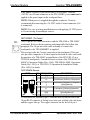
Crestron TPS-4500IMPC
Interface Module
Operations Guide
This document was prepared and written by the Technical Documentation department at:
Crestron Electronics, Inc.
15 Volvo Drive
Rockleigh, NJ 07647
1-888-CRESTRON
All brand names, product names and trademarks are the property of their respective owners.
©2003 Crestron Electronics, Inc.
Crestron TPS-4500IMPC
Interface Module
Contents
Interface Module: TPS-4500IMPC
1
Introduction......................................................................................1
Features & Functions.............................................................1
Specifications.........................................................................1
Physical Description ..............................................................2
Industry Compliance..............................................................5
Setup.................................................................................................5
Network Wiring .....................................................................5
Hardware Hookup..................................................................7
Problem Solving...............................................................................8
Troubleshooting.....................................................................8
Further Inquiries ..................................................................10
Future Updates.....................................................................10
Return and Warranty Policies ........................................................11
Merchandise Returns / Repair Service ................................11
CRESTRON Limited Warranty ..........................................11
Operations Guide - DOC. 6163
Contents • i
Crestron TPS-4500IMPC
Interface Module
Interface Module: TPS-4500IMPC
Introduction
Features & Functions
The TPS-4500IMPC is an interface module designed for, and included
with the Crestron TPS-4500 and TPS-4500V tilt touchpanels. The sleek
design of the touchpanel base left little room for all the connectors that
define the touchpanel's versatility. Furthermore, since the panel is not a
stationary user interface, it is impractical to have an excessive number of
cable connections directly to the touchpanel. As a result, it was necessary
to connect the touchpanel to an interface module that could offer
additional space for interconnections.
Specifications
The following table provides a summary of specifications for the
TPS-4500IMPC.
Specifications of the TPS-4500IMPC
SPECIFICATION
Optional Power Pack
Dimensions & Weight
Operations Guide - DOC. 6163
DETAILS
PW-2420RU (24 VDC, 2.0 A, Regulated)
Height: 1.25 in (3.18 cm)
Width: 5.82 in (14.79 cm)
Depth: 3.50 in (8.89 cm)
Weight: 12.4 oz (0.36 kg)
Interface Module: TPS-4500IMPC • 1
Interface Module
Crestron TPS-4500IMPC
Physical Description
The TPS-4500IMPC, shown in the following diagram, is supplied with
the TPS-4500 and TPS-4500V tilt touchpanels. The module is housed in
a black enclosure with labeling. An AC adapter port, network connector,
and video input connectors are located on one side of the unit. The
opposite side provides a video input signal selector switch, and
network/video connections to the touchpanel. The TPS-4500IMPC also
has mounting feet to secure the unit to a mounting surface.
Physical Views of the TPS-4500IMPC
SIDE VIEW
ROTATED 180°
5.82 in
5.32 in (14.78 cm)
(13.52 cm)
0.25 in
(0.64 cm)
3.50 in
(8.89 cm)
1.14 in
(2.89 cm)
2.81 in
(7.12 cm)
1.12 in
(2.84 cm)
Ø 0.16 in
(0.41 cm)
6 PLACES
0.27 in
(0.69 cm)
THESE DIMENSIONS ARE THE SAME
FOR BOTH SIDES OF THE UNIT
1.25 in
(3.18 cm)
Ports
There are five ports that serve various functions on the TPS-4500IMPC.
Refer to the following diagrams and descriptions of each port.
2 • Interface Module: TPS-4500IMPC
Operations Guide - DOC. 6163
Crestron TPS-4500IMPC
Interface Module
NTSC/PAL VIDEO
The NTSC/PAL video input consists of three connectors; two BNC
connectors for unbalanced video signals and one 6-pin mini-connector
for twisted pair wiring of balanced video signals. The video signal is
connected to these ports and requires a TPS-4500V or installation of the
TPS-VID-1 or TPS-VID-2 video card in a TPS-4500 touchpanel to
display video. Consult the latest revision of the TPS-4500V & 4500LV
Operations Guide (Doc. 6160), TPS-4500 & 4500L Operations Guide
(Doc. 5891), or TPS-VID-1/2 Operations & Installation Guide (Doc.
6059) for details. Use either the two BNC connectors or the six-pin
connector for twisted pair wiring when connecting a video source.
NOTE: BNC connectors are physically located next to the twisted pair
connectors. Image is for illustration purposes only. Refer to the physical
view of the TPS-4500IMPC on page 2 for actual connector positions.
NOTE: The TPS-4500IMPC allows the use of either balanced or
unbalanced signals for video input. To select the signal type to be used,
the DIP switches located on the opposite side of the device must be set in
the correct position. Refer to “BAL/COAX” on page 5 for more
information.
NET
This four-pin connector is used to connect to a Crestron control system
and other Cresnet peripherals in a system. It also provides network power
to the touchpanel if an external power pack is not used. If making
network connections to a control system or Cresnet peripherals, refer to
“Network Wiring” on page 5.
24 VDC, 2.0A (Power Supply)
24VDC
2.0A
This female connector is used to supply 24 VDC power to the
TPS-4500IMPC and the touchpanel from an optional power pack
(Crestron model PW-2420RU). When power is supplied to the TPS4500IMPC through this connector, a Cresnet power connection is not
required to display video on the touchpanel.
CAUTION: Use only Crestron power supplies for Crestron equipment.
Failure to do so could cause equipment damage or void the Crestron
warranty.
Operations Guide - DOC. 6163
Interface Module: TPS-4500IMPC • 3
Interface Module
Crestron TPS-4500IMPC
CAUTION: If power is provided to the TPS-4500IMPC from the
+24VDC on a Cresnet connector or the PW-2420RU, power must not be
applied to the power input on the touchpanel base.
NOTE: When power is supplied through this connector, Crestron
recommends disconnecting the +24 VDC on the Cresnet connector (if it
is connected).
NOTE: Use care in wiring installations to avoid applying 24 VDC power
to Cresnet wiring from multiple sources.
NET/VIDEO (To Panel)
NET/
VIDEO
1
This 10-pin RJ-45 connection mates with the TPS-4500 or TPS-4500V
touchpanel. Refer to the descriptions and pinout table that follow this
paragraph. The 10-pin net/video cable assembly to connect the
touchpanel to the TPS-4500IMPC is supplied.
This port provides the Cresnet connection to the touchpanel. This port
also provides composite or S-video input for the built-in video card (with
the purchase of a TPS-4500V or installation of the TPS-VID-1/2 in a
TPS-4500 touchpanel). Consult the latest revision of the TPS-4500V &
4500LV Operations Guide (Doc. 6160), TPS-4500 & 4500L Operations
Guide (Doc. 5891), or TPS-VID-1/2 Operations & Installation Guide
(Doc. 6059) for details.
NET/VIDEO Pinouts
TYPE
PIN DESIGNATION
10-pin RJ-45
Pin 1
Pin 1
1
2
3
4
5
6
7
8
9
10
+24V
GND
C+
CY
Z
Y+
YGND
+24V
DESCRIPTION
Power (Network)
Ground (Network)
Chrominance (Positive) /Composite 2
Chrominance (Negative) /Composite 2
Data (Network)
Data (Network)
Luminance (Positive)/Composite 1
Luminance (Negative)/Composite 1
Ground (Network)
Power (Network)
To determine the location of pin 1, hold the cable so that the end of the
10-pin RJ-45 connector is facing away from you, with the clip side down
and the copper side up. The copper connector on the far left is pin 1.
4 • Interface Module: TPS-4500IMPC
Operations Guide - DOC. 6163
Crestron TPS-4500IMPC
Interface Module
CAUTION: The 10-pin RJ-45 net/video connector cable supplied by
Crestron is a custom cable and is the only one that should be used. The
end of the cable has a metal shield that is required to protect the
equipment. Using non-Crestron cables will result in damage to the
product.
BAL/COAX
While not a port, these DIP switches are used to select which video
connections (balanced or unbalanced) to use when receiving video
signals. When used with a TPS-4500 with TPS-VID-2 installed, each
composite video signal can come in on either the twisted pair (balanced)
or coaxial (unbalanced) connector. When used with a TPS-4500V or
TPS-4500 with TPS-VID-1 installed, the video signal (S-video or
composite) can be received over the twisted pair (balanced) or coaxial
(unbalanced) connectors. As long as a switch is in the appropriate
position, a signal can be connected to either the BNC or twisted-pair
connector.
To select the twisted pair connector for balanced video, the DIP switch
for the respective video source must be in the “UP” position. To use the
coaxial connector(s) for unbalanced video, the DIP switch must be in the
“DOWN” position.
Industry Compliance
As of the date of manufacture, the TPS-4500IMPC has been tested and
found to comply with specifications for CE marking and standards per
EMC and Radiocommunications Compliance Labelling (N11785).
Setup
Network Wiring
CAUTION: Use only Crestron power supplies for Crestron equipment.
Failure to do so could cause equipment damage or void the Crestron
warranty.
Operations Guide - DOC. 6163
Interface Module: TPS-4500IMPC • 5
Interface Module
Crestron TPS-4500IMPC
CAUTION: Possible equipment damage if miswired.
NOTE: When installing network wiring, refer to the latest revision of the
wiring diagram(s) appropriate to your specific system configuration,
available from the Downloads | Product Manuals | Wiring Diagrams
section of the Crestron website (www.crestron.com).
NOTE: Do not power up system until all wiring is verified. Care should
be taken to ensure data (Y, Z) and power (24, G) connections are not
crossed.
NOTE: All network wiring must consist of two twisted-pairs. One
twisted pair is the +24V conductor and the GND conductor and the other
twisted pair is the Y conductor and the Z conductor.
NOTE: For larger networks (i.e., greater than 28 network devices), it
may be necessary to add a Cresnet Hub/Repeater (CNXHUB) to maintain
signal quality throughout the network. Also, for networks with lengthy
cable runs or varying types of network devices, it may be desirable to add
a hub/repeater after only 20 network devices.
When calculating the wire gauge for a particular network run, the length
of the run and the power factor of each network unit to be connected
must be taken into consideration. If network units are to be daisy-chained
on the run, the power factor of each network unit to be daisy-chained
must be added together to determine the power factor of the entire chain.
The length of the run in feet and the power factor of the run should be
used in the following resistance equation to calculate the value on the
right side of the equation.
Resistance Equation
R < 40,000
L x PF
Where: R = Resistance (refer to table below).
L = Length of run (or chain) in feet.
PF = Power factor of entire run (or chain).
The required wire gauge should be chosen such that the resistance value
is less than the value calculated in the resistance equation. Refer to the
following table.
6 • Interface Module: TPS-4500IMPC
Operations Guide - DOC. 6163
Crestron TPS-4500IMPC
Interface Module
Wire Gauge Values
RESISTANCE (R)
WIRE GAUGE
4
16
6
18
10
20
15
22
13
Doubled CAT5
8.7
Tripled CAT5
NOTE: When daisy-chaining Cresnet units, strip the ends of the wires
carefully to avoid nicking the conductors. Twist together the ends of the
wires that share a pin on the network connector, and tin the twisted
connection. Apply solder only to the ends of the twisted wires. Avoid
tinning too far up the wires or the end becomes brittle. Insert the tinned
connection into the Cresnet connector and tighten the retaining screw.
Repeat the procedure for the other three conductors.
Hardware Hookup
The TPS-4500IMPC serves as an interface between the touchpanel and
the Cresnet system. Refer to the illustration after this paragraph for
proper connections; apply power last. When making network connections
to a control system or Cresnet peripherals, refer to “Network Wiring” on
page 5. It is not necessary to make connections to a video source unless a
TPS-4500V touchpanel is used or a TPS-VID-1/2 has been installed into
a TPS-4500 touchpanel and a video window object resides on a page
within the uploaded Crestron VisionTools® Pro-e (VT Pro-e) project.
NOTE: When connecting the net/video cable from the interface module
to the touchpanel, exceeding a cable length of 30 feet will significantly
degrade the video signal. To maintain high-quality video, DO NOT
daisy-chain cables or Crestron TPSBLOCK-10 cables longer than 30
feet. Contact Crestron for the maximum available cable length.
Operations Guide - DOC. 6163
Interface Module: TPS-4500IMPC • 7
Interface Module
Crestron TPS-4500IMPC
Hardware Hookup for the TPS-4500IMPC
CONNECT TO 10-POSITION
NET/VIDEO PORT ON
TOUCHPANEL
BALANCED "Y" FOR S-VIDEO OR
COMPOSITE VIDEO
BALANCED "C" FOR S-VIDEO OR
COMPOSITE 2 FOR COMPOSITE
VIDEO (TPS-VID-2 ONLY)
UNBALANCED "C" FOR
S-VIDEO OR COMPOSITE 2
FOR COMPOSITE VIDEO
(TPS-VID-2 ONLY)
UNBALANCED "Y"
FOR S-VIDEO OR
COMPOSITE VIDEO
CONNECT TO CONTROL
SYSTEM OR CRESNET
PERIPHERALS
SELECT BALANCED (TWISTED
PAIR) OR COAX (UNBALANCED)
FOR EACH VIDEO SIGNAL
CONNECT OPTIONAL POWER
PACK PW-2420RU
Problem Solving
Troubleshooting
The following table provides corrective action for possible trouble
situations. If further assistance is required, please contact a Crestron
customer service representative.
TPS-4500IMPC Troubleshooting
TROUBLE
POSSIBLE CAUSE(S)
CORRECTIVE ACTION
No power
to the
touchpanel.
Improper cable being
used.
Use the NET/VIDEO cable
supplied with the
touchpanel.
(continued on next page)
8 • Interface Module: TPS-4500IMPC
Operations Guide - DOC. 6163
Crestron TPS-4500IMPC
Interface Module
TPS-4500IMPC Troubleshooting (continued)
TROUBLE
POSSIBLE CAUSE(S)
CORRECTIVE ACTION
Touchpanel
does not
function.
Touchpanel is not
receiving power.
Confirm that power is
supplied via the power
pack or the Cresnet
connector (not both).
Use Viewport (via SIMPL
Windows or VT Pro-e) to
poll the network. Verify
network connection to the
touchpanel.
Verify proper connections
on the touchpanel and
TPS-4500IMPC.
Verify that the supplied
10-pin net/video cable
assembly is used to
connect the NET/VIDEO
port of the touchpanel to
the TPS-4500IMPC.
Check DIP switch settings
on TPS-4500IMPC.
Follow installation
procedures for
TPS-VID-1/2.
Select the proper video
input configuration in the
touchpanel configuration
SETUP MENU.
Make sure that video
window object resides in
project, re-compile, and
reload.
Inspect connector pins. If
bent, carefully restraighten. If broken,
contact Crestron customer
service.
Touchpanel is not
communicating to the
network.
Video
window on
touchpanel
has no
display.
Improper video
connection.
Incorrect video cable
used.
Incorrect video format
selection.
TPS-VID-1/2 improperly
installed in TPS-4500.
Incorrect video format
selection.
Incorrect VT Pro-e
project file loaded.
Damaged connector
pins.
(continued on next page)
Operations Guide - DOC. 6163
Interface Module: TPS-4500IMPC • 9
Interface Module
Crestron TPS-4500IMPC
TPS-4500IMPC Troubleshooting (continued)
TROUBLE
POSSIBLE CAUSE(S)
CORRECTIVE ACTION
Video
colors are
wrong
and/or
moving.
Touchpanel is set to
auto-detect or S-video
when two composite
signals are plugged into
the TPS-4500IMPC.
Switch to “composite”
video.
Further Inquiries
If after reviewing this Operations Guide, you cannot locate specific
information or have questions, please take advantage of Crestron's award
winning customer service team by calling:
• In the US and Canada, call Crestron’s corporate headquarters at
1-888-CRESTRON [1-888-273-7876].
• In Europe, call Crestron International at +32-15-50-99-50.
• In Asia, call Crestron Asia at +852-2341-2016.
• In Latin America, call Crestron Latin America at
+5255-5093-2160.
• In Australia and New Zealand, call Crestron Pacific at
+613-9480-2999.
Future Updates
As Crestron improves functions, adds new features, and extends the
capabilities of the TPS-4500IMPC, additional information may be made
available as manual updates. These updates are solely electronic and
serve as intermediary supplements prior to the release of a complete
technical documentation revision.
Check the Crestron website (www.crestron.com) periodically for manual
update availability and its subjective value. Updates are available from
the Download | Product Manuals section and are identified as an
“Addendum” in the Download column.
10 • Interface Module: TPS-4500IMPC
Operations Guide - DOC. 6163
Crestron TPS-4500IMPC
Interface Module
Return and Warranty Policies
Merchandise Returns / Repair Service
1.
No merchandise may be returned for credit, exchange, or service without prior
authorization from CRESTRON. To obtain warranty service for CRESTRON
products, contact the factory and request an RMA (Return Merchandise
Authorization) number. Enclose a note specifying the nature of the problem, name
and phone number of contact person, RMA number, and return address.
2.
Products may be returned for credit, exchange, or service with a CRESTRON Return
Merchandise Authorization (RMA) number. Authorized returns must be shipped
freight prepaid to CRESTRON, Cresskill, N.J., or its authorized subsidiaries, with
RMA number clearly marked on the outside of all cartons. Shipments arriving freight
collect or without an RMA number shall be subject to refusal. CRESTRON reserves
the right in its sole and absolute discretion to charge a 15% restocking fee, plus
shipping costs, on any products returned with an RMA.
3.
Return freight charges following repair of items under warranty shall be paid by
CRESTRON, shipping by standard ground carrier. In the event repairs are found to
be non-warranty, return freight costs shall be paid by the purchaser.
CRESTRON Limited Warranty
CRESTRON ELECTRONICS, Inc. warrants its products to be free from manufacturing defects in
materials and workmanship under normal use for a period of three (3) years from the date of
purchase from CRESTRON, with the following exceptions: disk drives and any other moving or
rotating mechanical parts, pan/tilt heads and power supplies are covered for a period of one (1)
year; touchscreen display and overlay components are covered for 90 days; batteries and
incandescent lamps are not covered.
This warranty extends to products purchased directly from CRESTRON or an authorized
CRESTRON dealer. Purchasers should inquire of the dealer regarding the nature and extent of the
dealer's warranty, if any.
CRESTRON shall not be liable to honor the terms of this warranty if the product has been used in
any application other than that for which it was intended, or if it has been subjected to misuse,
accidental damage, modification, or improper installation procedures. Furthermore, this warranty
does not cover any product that has had the serial number altered, defaced, or removed.
This warranty shall be the sole and exclusive remedy to the original purchaser. In no event shall
CRESTRON be liable for incidental or consequential damages of any kind (property or economic
damages inclusive) arising from the sale or use of this equipment. CRESTRON is not liable for
any claim made by a third party or made by the purchaser for a third party.
CRESTRON shall, at its option, repair or replace any product found defective, without charge for
parts or labor. Repaired or replaced equipment and parts supplied under this warranty shall be
covered only by the unexpired portion of the warranty.
Except as expressly set forth in this warranty, CRESTRON makes no other warranties, expressed
or implied, nor authorizes any other party to offer any warranty, including any implied warranties
of merchantability or fitness for a particular purpose. Any implied warranties that may be imposed
by law are limited to the terms of this limited warranty. This warranty statement supercedes all
previous warranties.
Trademark Information
All brand names, product names, and trademarks are the sole property of their respective owners. Windows is a registered
trademark of Microsoft Corporation. Windows95/98/Me and WindowsNT/2000 are trademarks of Microsoft Corporation.
Operations Guide - DOC. 6163
Interface Module: TPS-4500IMPC • 11
Crestron Electronics, Inc.
15 Volvo Drive Rockleigh, NJ 07647
Tel: 888.CRESTRON
Fax: 201.767.7576
www.crestron.com
Operations Guide - DOC. 6163
08.03
Specifications subject to
change without notice.


![FRONIUS IG US [42,0410,1089]](http://vs1.manualzilla.com/store/data/005774043_1-689bd6c2a055f0ab88c64924d7fd22c0-150x150.png)