1
RAPIER SWITCH
USER GUIDE
Software Release 2.6.1
2
Rapier Switch User Guide for Software Release 2.6.1
Document Number C613-02025-00 REV C.
Copyright © 2003 Allied Telesyn International, Corp.
960 Stewart Drive Suite B, Sunnyvale CA 94086, USA.
All rights reserved. No part of this publication may be reproduced without prior written
permission from Allied Telesyn.
Allied Telesyn International, Corp. reserves the right to make changes in specifications
and other information contained in this document without prior written notice. The
information provided herein is subject to change without notice. In no event shall Allied
Telesyn be liable for any incidental, special, indirect, or consequential damages
whatsoever, including but not limited to lost profits, arising out of or related to this
manual or the information contained herein, even if Allied Telesyn has been advised of,
known, or should have known, the possibility of such damages.
All trademarks are the property of their respective owners.
Contents
CHAPTER 1
Introduction
Introducing the Rapier Series Switch ................................................................. 7
Why Read this User Guide? ............................................................................... 7
Where To Find More Information ...................................................................... 8
The Rapier Series Switch Documentation Set .............................................. 8
Online Technical Support ............................................................................ 9
Features of the Rapier Series Switch .................................................................. 9
Management Features .............................................................................. 10
Software Features .................................................................................... 10
Special Feature Licences ........................................................................... 11
Warning about FLASH memory ....................................................................... 12
CHAPTER 2
Getting Started with the Command Line Interface (CLI)
This Chapter ...................................................................................................
Connecting a Terminal or PC ...........................................................................
Terminal Communication Parameters ..............................................................
Logging In ......................................................................................................
Assigning an IP Address ..................................................................................
Setting Routes ................................................................................................
Changing a Password .....................................................................................
Choosing a Password ......................................................................................
Using the Commands .....................................................................................
Aliases ......................................................................................................
Getting Command Line Help ..........................................................................
Enabling Special Feature Licences ....................................................................
Setting System Parameters ..............................................................................
CHAPTER 3
13
14
14
15
15
16
17
17
18
19
19
20
20
Getting Started with the Graphical User Interface (GUI)
This Chapter ...................................................................................................
What is the GUI? ............................................................................................
Accessing the Switch via the GUI ....................................................................
Browser and PC Setup ..............................................................................
Establishing a Connection to the Switch ...................................................
Secure Access ...........................................................................................
System Status ...........................................................................................
Using the GUI: Navigation and Features ..........................................................
The Configuration Menu ..........................................................................
Using Configuration Pages .......................................................................
The Management Menu ...........................................................................
The Monitoring Menu ..............................................................................
21
22
22
22
24
29
31
32
32
32
36
36
4
Rapier Switch User Guide
The Diagnostics Menu ..............................................................................
Changing the Password ............................................................................
Context Sensitive GUI Help .......................................................................
Saving Configuration Entered with the GUI ..............................................
Combining GUI and CLI Configuration .....................................................
Configuring Multiple Devices ....................................................................
Upgrading the GUI .........................................................................................
Troubleshooting ..............................................................................................
Deleting Temporary Files ...........................................................................
Accessing the Switch via the GUI ..............................................................
Traffic Flow ...............................................................................................
IP Addresses and DHCP ............................................................................
Time and NTP ...........................................................................................
Loading Software .....................................................................................
CHAPTER 4
Operating the switch
This Chapter ...................................................................................................
User Accounts and Privileges ...........................................................................
Normal Mode and Security Mode ...................................................................
Remote Management .....................................................................................
Storing Files in FLASH Memory ........................................................................
Using Scripts ...................................................................................................
Saving the Switch’s Configuration ............................................................
Storing Multiple Scripts ............................................................................
Loading and Uploading Files ...........................................................................
File Naming Conventions ..........................................................................
Loading Files ............................................................................................
Setting LOADER Defaults ..........................................................................
Example: Load a Patch File Using HTTP .....................................................
Uploading Files From the Switch ...............................................................
Example: Upload a Configuration File Using TFTP ......................................
More information .....................................................................................
Upgrading Switch Software ............................................................................
Example: Upgrade to a New Software Release Using TFTP .........................
Example: Upgrade to a new patch file ......................................................
Using the Built-in Editor ..................................................................................
SNMP and MIBs ..............................................................................................
For More About Operations and Facilities ........................................................
CHAPTER 5
36
37
37
37
38
38
38
40
40
40
41
42
42
43
45
45
47
50
51
52
52
53
53
53
54
55
55
56
56
57
57
59
60
61
62
62
Layer 2 Switching
Switch Ports ....................................................................................................
Enabling and Disabling Switch Ports .........................................................
Autonegotiation of Port Speed and Duplex Mode .....................................
Port Trunking ...........................................................................................
Packet Storm Protection ...........................................................................
Port Mirroring ..........................................................................................
Port security .............................................................................................
Virtual Local Area Networks (VLANs) ...............................................................
VLAN Tagging ..........................................................................................
VLAN Membership of Untagged Packets ..................................................
Creating VLANs ........................................................................................
Summary of VLAN tagging rules ...............................................................
Protected VLANs ......................................................................................
VLAN Interaction with STPs and Trunk Groups ..........................................
Generic VLAN Registration Protocol (GVRP) .....................................................
Layer 2 Switching Process ...............................................................................
The Ingress Rules ......................................................................................
The Learning Process ................................................................................
65
65
68
69
71
72
73
74
75
78
79
81
81
81
82
82
82
83
Software Release 2.6.1
C613-02025-00 REV C
5
The Forwarding Process ............................................................................ 84
Layer 2 Filtering ........................................................................................ 85
The Egress Rules ....................................................................................... 87
Quality of Service ............................................................................................ 87
Spanning Tree Protocol (STP) ........................................................................... 89
Spanning Tree Modes ............................................................................... 89
Spanning Tree and Rapid Spanning Tree Port States .................................. 90
Overlapping VLANs belonging to multiple Spanning Tree instances ........... 91
Configuring STP ....................................................................................... 92
Interfaces to Layer 3 Protocols ....................................................................... 101
IGMP Snooping ............................................................................................ 101
Triggers ......................................................................................................... 104
CHAPTER 6
Layer 3
Internet Protocol (IP) .....................................................................................
IP Multicasting ..............................................................................................
Routing Information Protocol (RIP) ................................................................
Novell IPX .....................................................................................................
AppleTalk ......................................................................................................
Resource Reservation Protocol (RSVP) ............................................................
CHAPTER 7
Maintenance and Troubleshooting
This Chapter .................................................................................................
How the Switch Starts Up .............................................................................
How to Avoid Problems ................................................................................
What to Do if You Clear FLASH Memory Completely .....................................
What To Do if ISDN Fails to Connect .............................................................
What to Do if the PPP Link Disconnects Regularly ..........................................
What to Do if Passwords are Lost ..................................................................
Getting the Most Out of Technical Support ...................................................
Resetting Switch Defaults .............................................................................
Checking Connections Using PING ................................................................
Troubleshooting IP Configurations ................................................................
Troubleshooting DHCP IP Addresses ..............................................................
Troubleshooting IPX Configurations ..............................................................
Using Trace Route for IP Traffic ......................................................................
Software Release 2.6.1
C613-02025-00 REV C
106
106
107
107
108
109
111
112
113
115
116
116
116
117
118
118
119
120
121
123
Chapter 1
Introduction
Introducing the Rapier Series Switch
Congratulations on purchasing the Rapier Series Layer 3 Fast Ethernet Switch,
which combines wire speed Layer 2 and Layer 3 IP switching with a powerful
multiprotocol routing software suite.
This guide introduces the Rapier Series Switch and will guide you through the
most common uses and applications of your new switch. Getting started will
not take long—many applications are set up in just a few minutes. If you have
any questions about the switch, contact your authorised distributor or reseller.
Your Rapier Series Switch is supplied with default settings which enable it to
operate as a Layer 2 switch immediately, without any configuration. Even if
this is all you want to do, you should still gain access to the switch
configuration, if only to change the manager password to prevent unauthorised
access.
To change the switching configuration, and to take advantage of the advanced
routing features, you will need to enter detailed configuration. The switch has
both a Command Line Interface (CLI) and a Graphical User Interface (GUI) for
configuration and management. Before you can use the GUI, you will need to
login to the switch and use its CLI to allocate an IP address to at least one
interface.
Why Read this User Guide?
Before you use your switch in a live network, please read this guide. The guide
tells you how to access and use the Command Line Interface (CLI) and
Graphical User Interface (GUI) to configure the switch software. It then
introduces a number of common switch functions and how to configure them
using the CLI. For more detailed descriptions of all commands, display
outputs, and background information, see the Software Reference. For
information on configuration using the GUI, see the context-sensitive online
GUI help.
8
Rapier Switch User Guide
This user guide is organised into the following chapters:
■
Chapter 1, Introduction gives an overview of the switch features and of the
documentation supplied with your switch.
■
Chapter 2, Getting Started with the Command Line Interface (CLI) describes
how to gain access to the command line interface.
■
Chapter 3, Getting Started with the Graphical User Interface (GUI) describes
how to access and use the graphical user interface, including
troubleshooting the GUI.
■
Chapter 4, Operating the switch introduces general operation, management
and support features, including loading and installing support files and
new releases.
■
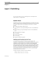
Chapter 5, Layer 2 Switching describes how to configure Layer 2 switching
features, including switch ports and VLANs.
■
Chapter 6, Layer 3 outlines some of the switch’s Layer 3 features, including
IP, IP multicasting, IPX and Appletalk.
■
Chapter 7, Maintenance and Troubleshooting describes some of the commands
you can use to monitor the switch and diagnose faults.
Where To Find More Information
Before installing the switch and any expansion options, read the important
safety information in the AT-8800 Series Switch Safety and Statutory Information
booklet.
Follow the Quick Install Guide’s step-by-step instructions for physically
installing the switch.
The Rapier Switch Hardware Reference gives detailed information about the
equipment hardware.
The context-sensitive online GUI help gives descriptions of each page and
element of the GUI.
Once you are familiar with the basic operations of the switch, use the Rapier
Series Switch Software Reference for full descriptions of routing features and
command syntax.
The Rapier Series Switch Documentation Set
The documentation set for the Rapier Series Switch includes:
■
Rapier Series Switch Safety and Statutory Information
■
Rapier Series Switch Quick Install Guide
Software Release 2.6.1
C613-02025-00 REV C
Introduction
9
■
Rapier Series Switch Documentation and Tools CD-ROM
The Rapier Series Switch Documentation Set in Adobe Acrobat PDF format
is bundled with every switch—the complete reference to installing,
configuring and managing the switch, including detailed descriptions of all
commands.
The CD-ROM includes the following PDF documents:
•
Rapier Series Switch Safety and Statutory Information
•
Rapier Series Switch Quick Install Guide
•
Rapier Switch Hardware Reference
•
Rapier Series Switch Software Reference
The CD-ROM also includes:
•
AT-TFTP Server for Windows, for downloading software releases,
scripts and other files to or from an Rapier switch.
•
Adobe Acrobat Reader for Windows for viewing and printing the
online documentation in PDF format. Get instant access to information
with full-text searching of PDF documents by keyword or phrase.
•
Microsoft Internet Explorer.
•
A demonstration version of F-Secure’s Secure Shell client for Windows.
•
Information about other Allied Telesyn routing and switching
products.
Online Technical Support
For online support for your Rapier Series Switch, see our online support page
at http://www.alliedtelesyn.co.nz/support/ar8800/
This page also contains the latest switch software releases, patches and GUI
resource files. Use the LOAD command to download software upgrades
directly from the Allied Telesyn web site to the router’s FLASH memory. Use
the SET INSTALL command to enable the new software (see “Upgrading Switch
Software” on page 57 for detailed instructions).
If you require further assistance, contact your authorised distributor or reseller.
Features of the Rapier Series Switch
There are two models in the AT-8800 Series, which provide either 48 or 24
10/100 TX Fast Ethernet ports. Both models also feature:
• 2 GBIC uplink ports
• Single PSU and redundant PSU (RPS)
• PAC interface connection
The software support provides wirespeed Layer 2 switching, including
support for Virtual LANs, and wirespeed Layer 3 switching of IP and IP
multicasting packets. In addition, the switch provides a wide array of
multiprotocol routing, security and network management features.
Software Release 2.6.1
C613-02025-00 REV C
10
Rapier Switch User Guide
Management Features
The following features enhance management of the switch:
■
A sophisticated and configurable event logging facility for monitoring and
alarm notification to single or multiple management centres.
■
Triggers for automatic and timed execution of commands in response to
events.
■
Scripting for automated configuration and centralised management of
configurations.
■
Dynamic Host Configuration Protocol (DHCP) for IP and IPv6. DHCP lets
you automatically assign IP addresses and other configuration information
to PCs and other hosts on TCP/IP networks.
■
Support for the Simple Network Management Protocol (SNMP), standard
MIBs and the Allied Telesyn Enterprise MIB, enabling the switch to be
managed by a separate SNMP management station.
■
Telnet client and server.
■
Secure Shell remote management.
■
An HTTP client that allows the direct download of files from a web server
to the router’s FLASH memory.
For complete descriptions of these software features, see the Rapier Series Switch
Software Reference.
Software Features
Rapier Layer 3 switches provide efficient and cost-effective multiprotocol
routing, terminal serving and integrated network management over wide area
networks and LANs. All models can run the same software suite and can
provide all of the following functions simultaneously (depending on the
hardware configuration):
■
Wide area networking via Point-to-Point Protocol.
■
Wide area networking via Frame Relay, and X.25, operating over
synchronous links up to 2Mb/s.
■
Basic Rate and Primary Rate access to Integrated Services Digital Network
(ISDN) services, with dial-on-demand and channel aggregation.
■
TCP/IP routing.
■
Novell® IPX routing.
■
AppleTalk routing.
■
Generic Routing Encapsulation (GRE) protocols.
■
IP multicast routing support, including Internet Group Management
Protocol (IGMP), Distance Vector Multicast Routing Protocol (DVMRP)
and Protocol Independent Multicast (PIM) Sparse and Dense Modes.
■
Ping Polling for determining device reachability and responding when a
device or link goes up or down.
■
IPv6 routing support, including stateless address autoconfiguration, RIPv6
and ICMPv6.
Software Release 2.6.1
C613-02025-00 REV C
Introduction
11
■
IPv6 multicast routing support, including Multicast Listener Discovery
(MLDv2) and Protocol Independent Multicast (PIM) Sparse and Dense
Modes.
■
OSPF, RIP (IP and Novell®), SAP (Novell®), EGP and BGP routing
protocols.
■
ARP, Proxy ARP and Inverse ARP address resolution protocols.
■
Sophisticated packet filtering.
■
Bridging.
■
Van Jacobson’s header compression, STAC LZS and Predictor compression,
and hardware-based and DES encryption.
■
Create secure Virtual Private Networks (VPNs) across the Internet or any
other public or shared IP network, using AT-VPNet.
■
Tunnelling of synchronous (HDLC) data through TCP/IP.
■
Terminal serving using Telnet, with local host nicknames.
■
Access to network printers via LPD or TCP streams.
■
Resource Reservation Protocol (RSVP) for delivering quality of service to
application data streams.
■
TPAD support for fast credit card authorisation transactions.
■
A fully featured, stateful inspection firewall.
■
IPsec-compliant IP security services.
■
Integration with a Public Key Infrastructure (PKI).
■
Virtual Router Redundancy Protocol (VRRP).
■
Border Gateway Protocol version 4 (BGP-4).
■
Load Balancing for distributing traffic among multiple resources.
■
Software Secure Sockets Layer (SSL).
■
Voice over IP (VoIP).
■
802.1x port authentication.
Special Feature Licences
You need a special feature licence and password to activate some special
features over and above the standard software release. Typically, these special
features are covered by government security regulations. Special feature
licences and passwords are quite separate and distinct from the standard
software release licences and passwords. Some of the software features that
require a special feature licence are:
Software Release 2.6.1
C613-02025-00 REV C
■
Triple DES S/W
■
Firewall SW
■
Firewall SMTP Application Gateway
■
Firewall HTTP Application Gateway
■
DES encryption
■
IPv6
■
IP Multicast routing: DVMRP and PIM-Sparse Mode
■
IPX routing
12
Rapier Switch User Guide
■
Demand IPX
■
IPX/SPX Spoofing
■
IPX Filtering (not between switch ports)
■
AppleTalk
■
Resource Reservation Protocol (RSVP)
■
BGP-4
■
Load balancer
Most software features that require a special feature licence are bundled into
one of the following special feature licence packs:
■
Full Layer 3 Feature Licence
■
Advanced Layer 3 Feature Licence
■
Security Pack Feature Licence
For more information about purchasing special feature licences, contact your
Allied Telesyn authorised distributor or reseller. For information on how to
enable special feature licences using the CLI, see “Enabling Special Feature
Licences” on page 20.
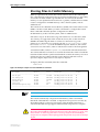
Warning about FLASH memory
Before you start to configure your switch, note that it is possible to enter
commands that can impact severely on your router’s performance.
DO NOT clear the FLASH memory completely. The software release files are
stored in FLASH, and clearing FLASH memory would leave no software to run
the switch.
While FLASH is compacting, do not restart the switch or use any commands
that affect the FLASH file subsystem. Do not restart the switch, or create, edit,
load, rename or delete any files until a message confirms that FLASH file
compaction is completed. Interrupting flash compaction may result in damage
to files. Damaged files are likely to prevent the switch from operating correctly.
For more information, see “How to Avoid Problems” on page 113 and “What to
Do if You Clear FLASH Memory Completely” on page 115.
Software Release 2.6.1
C613-02025-00 REV C
Chapter 2
Getting Started with the Command Line
Interface (CLI)
This Chapter
This chapter describes how to access the switch’s CLI, and provides basic
information about configuring the switch, including how to:
■
Physically connect a terminal or PC to the switch (see “Connecting a
Terminal or PC” on page 14 and the Quick Install Guide).
■
Set the Terminal Communication parameters to match the router’s settings
(see “Terminal Communication Parameters” on page 14).
■
Log in to the switch as a manager (see “Logging In” on page 15).
■
Configure IP addresses on the switch interfaces over which you will
manage the switch. This is necessary if you will access the switch using the
GUI or Telnet (see “Assigning an IP Address” on page 15).
■
Set routes (see “Setting Routes” on page 16)
■
Change the management password to limit unauthorised access to the
switch configuration (see “Changing a Password” on page 17).
■
Use the command line interface to control the switch software, including
creating aliases for often used character sequences (see “Using the
Commands” on page 18).
■
Set the online help file to gain access to command syntax help (see “Getting
Command Line Help” on page 19).
■
Enable any special feature licences (see “Enabling Special Feature Licences”
on page 20).
■
Set the name, location and contact details for the switch (see “Setting
System Parameters” on page 20).
14
Rapier Switch User Guide
Connecting a Terminal or PC
The first thing to do after physically installing the switch is to start a terminal
or terminal emulation session to access the switch. Then you can use the
command line interface (CLI) to configure the switch. If you wish to configure
the switch using the Graphical User Interface, you must first access the CLI and
assign an IP address to at least one interface.
You can use a PC running terminal emulation software as the manager console
instead of a terminal. Many terminal emulation applications are available for
the PC, but the most readily available is the HyperTerminal application
included in Microsoft® Windows™ 95, Windows™ 98, and Windows™ 2000.
In a normal Windows™ installation HyperTerminal is located in the
Accessories group. In Windows™ 2000, HyperTerminal is located in the Start >
Programs > Accessories > Communications menu.
The key to successfully using terminal emulation software with the switch is to
configure the communications parameters in the terminal emulation software
to match the default settings of the console port on the switch. For instructions
on how to configure HyperTerminal, see the Rapier Switch Hardware Reference.
To start a terminal session, connect to the switch in one of the following ways:
■
Connect a VT100-compatible terminal to the RS-232 Terminal Port (asyn0),
set the communications parameters on the terminal (Table 1 on page 14),
and press [Enter] a few times until the router’s login prompt appears
OR
■
Connect the COM port of a PC running terminal emulation software such
as Windows Terminal or HyperTerminal to the RS-232 Terminal Port
(asyn0), set the communications parameters on the terminal emulation
software (Table 1 on page 14), and press [Enter] a few times until the
router’s login prompt appears.
Terminal Communication Parameters
Check that the terminal or modem’s communication settings match the settings
of the asynchronous port. By default, the asynchronous port (also known as the
Console, RS-232, or Config port) on the switch is set to the parameters shown
in Table 1 on page 14:
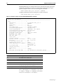
Table 1: Parameters for terminal communication
Parameter
Value
Baud rate
9600
Data bits
8
Parity
None
Stop bits
1
Flow control
Hardware
Refer to the user manual supplied with the terminal or modem for details of
how to change the communications settings for the terminal or modem.
Software Release 2.6.1
C613-02025-00 REV C
Getting Started with the Command Line Interface (CLI)
15
If a modem is connected, configure the switch to make and/or accept calls via
the modem. To set the CDCONTROL parameter to “CONNECT” and the
FLOW parameter to “HARDWARE”, enter the command:
SET ASYN CDCONTROL=CONNECT FLOW=HARDWARE
If the terminal or modem is used with communications settings other than the
default settings, then configure the asynchronous port to match the terminal or
modem settings using the SET ASYN command.
See the router’s online help or the Interfaces chapter in the Rapier Series Switch
Software Reference for more information on how to configure the asynchronous
port.
Logging In
When you access the switch from a terminal or PC connected to the RS-232
terminal port (asyn0), or via a Telnet or HTTP connection, you must enter a
login name and password to gain access to the command prompt. When the
switch is supplied, it has a manager account with an initial password friend.
Enter your login name at the login prompt:
login: manager
Enter the password at the password prompt:
password: friend
After you log into the manager account you can enter commands from this
document and from the Rapier Series Switch Software Reference.
Assigning an IP Address
To configure the switch to perform IP routing (for example, to access the
Internet) you need to configure IP. You also need to configure IP if you want to
manage the switch from a Telnet session or with the GUI. For detailed
instructions on accessing the switch with the GUI, see “Accessing the Switch via
the GUI” on page 22.
First enable IP, using the command:
ENABLE IP
Then, add an IP address to each of the switch interfaces that you want to
process IP traffic (for example, the default VLAN (vlan1)).
For the default VLAN, use the command:
ADD IP INTERFACE=vlan1 IPADDRESS=ipadd MASK=mask
where:
Software Release 2.6.1
C613-02025-00 REV C
■
ipadd is an unused IP address on your LAN.
■
mask is the subnet mask (for example 255.255.255.0)
16
Rapier Switch User Guide
If IP addresses on your LAN are assigned dynamically by DHCP, you can set
the switch to request an IP address from the DHCP server, using the
commands:
ADD IP INTERFACE=vlan1 IPADDRESS=DHCP
ENABLE IP REMOTEASSIGN
You do not need to set the MASK parameter because the subnet mask received
from the DHCP server is used.
If you use DHCP to assign IP addresses to devices on your LAN, and you want to
manage the switch within this DHCP regime, it is recommended that you set your
DHCP server to always assign the same IP address to the switch. This will enable you
to access the GUI by browsing to that IP address, and will also let you use the switch as
a gateway device for your LAN. If you need the switch's MAC address for this, it can be
displayed using the command SHOW SWITCH.
To change the IP address for an interface, enter the command:
SET IP INTERFACE=interface IPADDRESS=ipadd MASK=ipadd
When you are configuring the switch remotely, if you change the configuration (for
example, the VLAN membership) of the port over which you are configuring, the switch
is likely to break the connection.
For more information about switch ports and Virtual LANs (VLANs), see
Chapter 5, Layer 2 Switching in this document, and the Switching chapter in the
Rapier Series Switch Software Reference. For more information about IP
addressing and routing, see Chapter 6, Layer 3 in this document, and the Internet
Protocol (IP) chapter in the Rapier Series Switch Software Reference.
Setting Routes
The process of routing packets consists of selectively forwarding data packets
from one network to another. Your switch makes a decision to send a packet to
a particular network on information it learns dynamically from listening to the
selected route protocol and on the static information entered as part of the
configuration process. In addition, you can configure user-defined filters to
restrict the way packets are sent.
Your switch maintains a table of routes which holds information about routes
to destinations. The route table tells the switch how to find a remote network or
host. A route is uniquely identified by IP address, network mask, next hop,
ifIndex, protocol and policy. A list of routes comprises all the different routes to
a destination. The routes may have different metrics, next hops, policy or
protocol. A list of routes is uniquely identified by its IP address and net mask.
The routing table is maintained dynamically by using one or more routing
protocols such as RIP, EGP and OSPF. These act to exchange routing
information with other switches or hosts.
You can also add static routes to the route table to define default routes to
external switches or networks and to define subnets.
Software Release 2.6.1
C613-02025-00 REV C
Getting Started with the Command Line Interface (CLI)
17
To add a static route, enter the command:
ADD IP ROUTE=ipadd INTERFACE=interface NEXTHOP=ipadd
[CIRCUIT=miox-circuit] [DLCI=dlci]
[MASK=ipadd][METRIC=1..16] [METRIC1=1..16]
[METRIC2=1..65535][POLICY=0..7] [PREFERENCE=0..65535]
To displays the entire routing table, including both static and dynamic routes,
enter the command:
SHOW IP ROUTE
For more information about setting IP routes, see the Internet Protocol (IP)
chapter in the Rapier Series Switch Software Reference.
Changing a Password
You should change this password to prevent unauthorised access to the switch.
Enter the command:
SET PASSWORD
The switch prompts you for the current password, for the new password, and
for confirmation of the new password. The password can contain any printable
characters, and must be at least a minimum length, by default six characters.
(To change the default minimum length, see the SET USER command in the
Operations chapter, Rapier Series Switch Software Reference.)
Choosing a Password
All users, including managers, should take care in selecting passwords. Tools
exist that enable hackers to guess or test many combinations of login names
and passwords easily. The User Authentication Facility (UAF) provides some
protection against such attacks by allowing the manager to set the number of
consecutive login failures allowed and a lockout period when the limit is
exceeded.
However, the best protection against password discovery is to select a good
password and keep it secret. When choosing a password:
Software Release 2.6.1
C613-02025-00 REV C
■
Do make it six or more characters in length. The UAF enforces a minimum
password length, which the manager can change. The default is six
characters.
■
Do include both alphabetic (a–z) and numeric (0–9) characters.
■
Do include both uppercase and lowercase characters. The passwords
stored by the switch are case-sensitive, so “bgz4kal” and “Bgz4Kal” are
different.
■
Do avoid words found in a dictionary, unless combined with other random
alphabetic and numeric characters.
■
Do not use the login name, or the word “password” as the password.
■
Do not use your name, your mother’s name, your spouse’s name, your
pet’s name, or the name of your favourite cologne, actor, food or song.
18
Rapier Switch User Guide
■
Do not use your birth date, street number or telephone number.
■
Do not write down your password anywhere.
Make sure you remember the new password created as you cannot retrieve a
lost password. Recovery of access to the switch is complex.
Once you have logged into the manager account you are able to enter
commands from this guide and from the Rapier Series Switch Software Reference.
Using the Commands
You control the switch with commands described in this document and in the
Rapier Series Switch Software Reference. While the keywords in commands are
not case sensitive, the values entered for some parameters are (especially
passwords). The switch supports command line editing and recall. Command
line editing functions and keystrokes are shown in Table 2 on page 18.
Table 2: Command line editing functions and keystrokes .
Function
VT100 Terminal
Dumb terminal
Move cursor within command line ←, →
Not available
Delete character to left of cursor
[Delete] or [Backspace]
[Delete] or [Backspace]
Toggle between insert/overstrike
[Ctrl/O]
Not available
Clear command line
[Ctrl/U]
[Ctrl/U]
Recall previous command
↑ or [Ctrl/B]
[Ctrl/B]
Recall next command
↓ or [Ctrl/F]
[Ctrl/F]
Display command history
[Ctrl/C] or
SHOW PORT HISTORY
[Ctrl/C]
or SHOW PORT HISTORY
Clear command history
RESET PORT HISTORY
RESET PORT HISTORY
Recall matching command
[Tab] or [Ctrl/I]
[Tab] or [Ctrl/I]
The switch assumes that the width of the terminal screen is 80 characters, and
performs command line wrapping at the 80th column regardless of the setting
of the terminal. To execute a command the cursor does not need to be at the
end of the line. The default editing mode is insert mode. Characters are
inserted at the cursor position and any characters to the right of the cursor are
pushed to the right to make room. In overstrike mode, characters are inserted
at the cursor position and replace any existing characters.
Commands are limited to 1000 characters, excluding the prompt. Pathnames of
up to 256 characters, including file names, and file names up to 16 characters
long, with extensions of 3 characters, are supported.
Software Release 2.6.1
C613-02025-00 REV C
Getting Started with the Command Line Interface (CLI)
19
Aliases
The command line interface supports aliases. An alias is a short name for an
often-used longer character sequence. When the user presses [Enter] to execute
the command line, the command processor first checks the command line for
aliases and substitutes the replacement text. The command line is then parsed
and processed normally. Alias substitution is not recursive—the command line
is scanned only once for aliases.
Aliases are created and destroyed using the commands:
ADD ALIAS=name STRING=substitution
DELETE ALIAS=name
Getting Command Line Help
Online help is available for all switch commands. A multilingual, languageindependent online help facility provides help information via the command:
HELP [topic]
If a topic is not specified, a list of available topics is displayed. The HELP
command displays information from the system help file stored in FLASH
memory. The help file uses a simple mark-up language to identify topics,
access level (USER or MANAGER) and help text. Both standard ASCII and
Unicode character encodings are supported. Alternate help files can be
uploaded and stored in FLASH, then activated using the command:
SET HELP=helpfile
To display the current help file, enter the command:
SHOW SYSTEM
The help file is easily modified, for example to provide detailed site-specific
support information. The mark-up language specification and preprocessor
program are available from your authorised distributor or reseller.
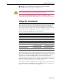
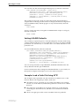
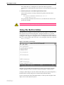
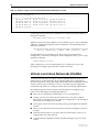
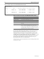
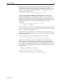
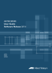
Also, typing a question mark “?” at the end of a partially completed command
displays a list of the parameters that may follow the current command line,
with the minimum abbreviations in uppercase letters (see Figure 1). The
current command line is then re-displayed, ready for further input.
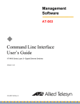
Figure 1: Using the question mark character (“?”) to display help for the current command.
Manager > ADD ?
Options : ACC APPletalk BGP CLASSifier BOOTp BRIDge DECnet FRamerelay GRE IP IPX
ISDN LAPD LOG MIOX NTP OSPF PERM PPP RADius SA SCript SNmp STReam STT TRIGger
TACacs USEr X25C X25T TDM
Manager > ADD ACC ?
Options : CALL SCript DOmainname
Manager > ADD ACC CALL ?
Options : DIrection DScript CScript RScript POrt ENcapsulation AUthentication
DOmainname
Software Release 2.6.1
C613-02025-00 REV C
20
Rapier Switch User Guide
Enabling Special Feature Licences
You must enable the special feature licence you have purchased before you can
use the licenced features. You will need the password provided by your
authorised distributor or reseller. The advanced upgrade licence and password
are different from the standard software release licence and password. The
licence cannot be transferred from one switch to another.
For software features that require a special feature licence see “Special Feature
Licences” on page 11.
You must order passwords for special feature licences from your authorised distributor
or reseller. You must specify the special feature licence bundle and the serial number(s)
of the switch(s) on which the special feature licences are to be enabled.
The password for a special feature licence is a string of at least 16 hexadecimal
characters. This password encodes the special feature, or features, covered by
the license, and the switch serial number. The password information is stored
in the router’s FLASH memory.
To enable or disable a special feature licence, enter the commands:
ENABLE FEATURE=feature PASSWORD=password
DISABLE FEATURE=feature
To list the current special feature licences, enter the command:
SHOW FEATURE[={featurename|index}]
Setting System Parameters
You can set some general system parameters to ensure the router’s
compatibility with the public network, and to aid network administration.
System name, location and contact parameters can help a remote network
administrator identify the switch. By convention the system name is the full
domain name. Set the name and location of the switch, for example:
SET SYSTEM NAME=nd1.co.nz
SET SYSTEM LOCATION=”Head Office, 3rd floor east”
and a contact name and phone number for the network administrator
responsible for the switch, for example:
SET SYSTEM CONTACT=”Anna Brown 03-456 789”
The name, location, and contact are strings 1 to 80 characters in length of any
printable character. If the string includes spaces enclose it in double quotes.
Set the router’s real time clock to the current local time in 24 hour notation
(hh:mm:ss), and to the current date (dd-mmm-yy, or dd-mmm-yyyy), for
example:
SET TIME=14:50:00
SET DATE=29-JAN-02 or
SET DATE=29-JAN-2003
Software Release 2.6.1
C613-02025-00 REV C
Chapter 3
Getting Started with the Graphical User
Interface (GUI)
This Chapter
This chapter describes how to access the switch’s HTTP-based Graphical User
Interface (GUI), and provides basic information about using the GUI,
including:
■
What is the GUI?
•
■
■
an introduction to the Graphical User Interface
Accessing the switch via the GUI:
•
browser and PC setup, including interaction with HTTP proxy servers
•
establishing a connection to your switch, including an example of
configuring SSL for secure access
•
the System Status page, the first GUI page you see
Using the GUI: navigation and features:
•
an overview of the menus
•
using configuration pages, with a description of key elements of GUI
pages
•
changing your password
•
using the context sensitive online help
•
saving your configuration
•
combining GUI and CLI configuration
•
configuring multiple devices
■
Upgrading the GUI
■
Troubleshooting
•
diagnosing and solving connection problems
•
using the GUI to troubleshoot the switch’s configuration.
22
Rapier Switch User Guide
What is the GUI?
The GUI (Graphical User Interface) is a web-based device management tool,
designed to make it easier to configure and monitor the switch. The GUI
provides an alternative to the CLI (Command Line Interface). Its purpose is to
make complicated tasks simpler and regularly performed tasks quicker.
The GUI relies on an HTTP server that runs on the switch, and a web browser
on the host PC. When you use the GUI to configure the switch, the GUI sends
commands to the switch and the switch sends the results back to your browser,
all via HTTP.
The tasks you may perform using the GUI are not as comprehensive as the
command set available on the CLI, but for some protocols, a few clicks of the
mouse will perform many commands.
The GUI is stored on the switch in the form of an embedded resource file, with
file extension rsc. Resource files are model-specific, with the model and
version encoded in the file name.
Accessing the Switch via the GUI
To use the GUI to configure the switch, you use a web browser to open a
connection to the switch’s HTTP server. Therefore, you need a PC, a web
browser and the switch. Supported browsers and operating systems, and the
settings you need on your PC and browser, are detailed in the following
section. Switch setup is detailed in “Establishing a Connection to the Switch” on
page 24.
Browser and PC Setup
The GUI requires a web browser installed on a PC. Table 3 shows supported
combinations of operating system and browser. A copy of Internet Explorer can
be found on the switch’s Documentation and Tools CD-ROM.
Table 3: Supported browsers and operating systems
IE 5.0
IE 5.5
IE 6.0
NS 6.2.2
NS 6.2.3
Windows 95
!
Windows 98
!
!
!
Windows ME
!
!
!
!
!
Windows 2000
!
!
!
!
!
Windows XP
!
!
!
!
!
JavaScript must be enabled. To enable JavaScript in Internet Explorer:
1.
From the Tools menu, select Internet Options
2.
Select the Security tab
3.
Click on the Custom Level button
4.
Under the Scripting section, ensure that “Active scripting” is enabled.
Software Release 2.6.1
C613-02025-00 REV C
Getting Started with the Graphical User Interface (GUI)
23
To enable JavaScript in Netscape 6.2.x:
1.
From the Edit menu, select Preference
2.
Select the Advanced menu option.
3.
Ensure that the “Enable JavaScript for Navigator” checkbox is checked.
The minimum screen resolution on the PC is 800x600.
HTTP Proxy Servers
An HTTP proxy server provides a security barrier between a private network’s
PCs and the Internet. The PCs send HTTP requests (and other web traffic) to
the server, which then forwards the requests appropriately. Similarly, the server
receives incoming HTTP traffic addressed to a PC on the private network, and
forwards it to the appropriate PC. Proxy servers can be used to block traffic
from undesirable websites, to log traffic flows, and to disallow cookies.
If your browser is configured to use a proxy server, and the switch is on your
side of the proxy server, you will need to set the browser to bypass proxy
entries for the IP address of the appropriate interface on the switch. (See
“Establishing a Connection to the Switch” on page 24 for information about giving
switch interfaces IP addresses.)
To ensure that your network’s security settings are not compromised, see your
network administrator for information about bypassing the proxy server on
your system.
To bypass the proxy server on Internet Explorer, if your browser administration
does not use a script, and the PC and the switch are in the same subnet:
1.
From the Tools menu, select Internet Options.
2.
Select the Connections tab and click the LAN Settings button.
3.
Check the “Bypass proxy server for local addresses” checkbox.
4.
If necessary, click the Advanced button and enter a list of local addresses.
To bypass the proxy server on Netscape, if your browser does not use a script:
Software Release 2.6.1
C613-02025-00 REV C
1.
From the Edit menu, select Preferences
2.
Click on the Advanced menu option to expand it.
3.
Select the Proxies menu option
4.
Enter the switch’s IP address in the “No Proxy for” list.
24
Rapier Switch User Guide
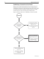
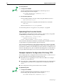
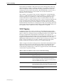
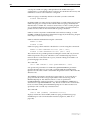
Establishing a Connection to the Switch
Before you start, consider how the switch fits into your network. If you are
installing a new switch, consider whether you want to configure it before
deploying it into the LAN, or want to configure it in situ. If you want to access
a switch that has already been configured, consider the relative positions of the
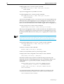
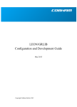
PC and the switch. The flow chart below summarises this process, and the
procedures that follow take you through each possibility in detail.
Figure 2: A summary of the process for establishing a connection via the GUI.
Start here
Is the router
already installed and
configured in
the LAN?
Determine the IP address
of an interface on the router
and browse to it.
Yes
See “Option 3: Connecting
to an Installed Switch” on
page 28.
No
Do you want
to configure the router
before installing it in
the LAN?
Connect your PC directly to
the router, give the router an
IP address and browse to it.
Yes
See “Option 1: Configuring
the Switch before
Installation” on page 25.
No
Install the router into the LAN,
give it an IP address and
browse to it.
See “Option 2: Installing
the Switch into the LAN”
on page 26.
Software Release 2.6.1
C613-02025-00 REV C
Getting Started with the Graphical User Interface (GUI)
25
Option 1: Configuring the Switch before Installation
Use this procedure if:
■
You want to configure the switch before installing it in your LAN.
■
You will be installing the switch at a remote office or a customer site and
want to configure it first.
■
You want a dedicated management PC permanently connected to the
switch.
1.
Select a PC to browse to the switch from
You can browse to the switch from any PC that is running a supported
operating system with a supported browser installed. See “Browser and PC
Setup” on page 22 for more information.
You need to know the PC’s subnet.
2.
Connect the PC to the switch
Use a straight-through Ethernet cable to connect an Ethernet card on the
PC to any one of the switch ports (see Figure 3).
Figure 3: Connecting a PC directly to the switch.
Rapier
You can browse to the switch through any VLAN, as long as you give that VLAN an IP
address (see below). These instructions assume you will use vlan1. The switch ports all
belong to vlan1 by default.
3.
Access the switch’s command line interface
Access the CLI from the PC, as described in “Connecting a Terminal or PC”
on page 14.
4.
Enable IP
ENABLE IP
5.
Assign the vlan1 interface an IP address in the same subnet as the PC
ADD IP INTERFACE=vlan1 IP=ipaddress MASK=mask
6.
Save the configuration and set the switch to use it on bootup
CREATE CONFIG=your-name.cfg
SET CONFIG=your-name.cfg
7.
On the PC, bypass the HTTP proxy server, if necessary
See “HTTP Proxy Servers” on page 23 for more information.
8.
Software Release 2.6.1
C613-02025-00 REV C
Point your web browser at the LAN interface’s IP address
26
Rapier Switch User Guide
9.
At the login prompt, enter the user name and password
The default username is manager:
User Name: manager
Password: friend
The System Status or System Hardware Details page is displayed (Figure 6
on page 31). Select options from the sidebar menu to configure and
manage the switch.
Option 2: Installing the Switch into the LAN
Use this procedure if:
■
You want to install the switch into the LAN before you configure it.
1.
Select a PC to browse to the switch from
You can browse to the switch from any PC that is running a supported
operating system with a supported browser installed, with JavaScript
enabled. See “Browser and PC Setup” on page 22 for more information.
You need to know the PC’s subnet.
2.
Plug the switch into the LAN
To install the switch into the same subnet as the PC:
Use an Ethernet cable to connect one of the switch ports to a device on the
LAN segment, for example, a hub, router or switch (see Figure 4).
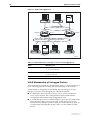
Figure 4: Connecting the switch into the same LAN segment as the PC
To install the switch into a different subnet than the PC:
Use an Ethernet cable to connect any one of the switch ports to a device on
the LAN segment in which you require the switch to work, for example, a
hub, router or switch (see Figure 5).
Figure 5: Configuring the switch from a PC in another subnet.
gateway
subnet
subnet
Rapier Switch
Software Release 2.6.1
C613-02025-00 REV C
Getting Started with the Graphical User Interface (GUI)
27
You can browse to the switch through any VLAN, as long as you give that VLAN an IP
address (see below). These instructions assume you will use vlan1. The switch ports all
belong to vlan1 by default.
3.
Access the switch’s command line interface
Access the CLI from the PC, as described in “Connecting a Terminal or PC”
on page 14.
4.
Enable IP
ENABLE IP
5.
Assign the vlan1 interface an IP address
ADD IP INTERFACE=vlan1 IP=ipaddress MASK=mask
If you use DHCP to assign IP addresses to devices on your LAN, and you want to
manage the switch within this DHCP regime, it is recommended that you set your
DHCP server to always assign the same IP address to the switch. This will enable you
to access the GUI by browsing to that IP address, and will also let you use the switch as
a gateway device for your LAN. If you need the switch's MAC address for this, you can
display it using the command SHOW SWITCH. To set the interface to obtain its IP
address by DHCP, use the commands:
ADD IP INTERFACE=VLAN1 IPADDRESS=DHCP and
ENABLE IP REMOTEASSIGN.
6. If the PC you want to browse from is in a different subnet from the switch,
give the switch a route to the PC
ADD IP ROUTE=PC-subnet INTERFACE=vlan1
NEXTHOP=gateway-ipaddress
where:
•
PC-subnet is the IP subnet address of the PC. For example, if the PC has
an IP address of 192.168.6.1 and a mask of 255.255.255.0, its subnet
address is 192.168.6.0.
•
gateway-ipaddress is the IP address of the gateway device that connects
the PC’s subnet with the switch’s subnet (Figure 5 on page 26).
7. If you want to be able to browse to the GUI securely, configure SSL (Secure
Sockets Layer)
See “Secure Access” on page 29 for more information.
8.
Save the configuration and set the switch to use it on bootup
CREATE CONFIG=filename.cfg
SET CONFIG=filename.cfg
9.
On the PC, bypass the HTTP proxy server, if necessary
See “HTTP Proxy Servers” on page 23 for more information.
Software Release 2.6.1
C613-02025-00 REV C
28
Rapier Switch User Guide
10. Point your web browser at the LAN interface’s IP address
For normal access, point your web browser to
http://ip-address
For secure access, point your web browser to
https://ip-address
where ip-address is the interface’s IP address.
11. At the login prompt, enter the user name and password
The default username is manager:
User Name: manager
Password: friend
The System Status or System Hardware Details page is displayed (Figure 6
on page 31). Select options from the sidebar menu to configure and
manage the switch.
Option 3: Connecting to an Installed Switch
Use this procedure if:
■
At least one interface on the switch already has an IP address, and the
switch is already installed in a LAN.
1.
Find out the IP address of the switch’s interface
Ask your system administrator. Alternatively, access the CLI, as described
in “Connecting a Terminal or PC” on page 14, and enter the command:
SHOW IP INTERFACE
You can browse to the switch through any VLAN, as long as you give that VLAN an IP
address (see below). These instructions assume you will use vlan1. The switch ports all
belong to vlan1 by default.
2.
Select a PC
You can browse to the GUI from any PC that:
•
has an IP address in the same subnet as the switch, or that the switch
has a route to
•
is running a supported operating system
•
has a supported browser installed, with JavaScript enabled
See “Browser and PC Setup” on page 22 for more information.
3.
If necessary, bypass the HTTP proxy server
See “HTTP Proxy Servers” on page 23 for more information.
Software Release 2.6.1
C613-02025-00 REV C
Getting Started with the Graphical User Interface (GUI)
4.
29
Browse to the switch
For normal access, point your web browser to
http://ip-address
where ip-address is the interface’s IP address.
To access the switch securely if SSL (Secure Sockets Layer) has been
configured on the interface, point your web browser to
https://ip-address
For more information about secure access, see “Secure Access” on page 29.
5.
At the login prompt, enter the user name and password
The default username is manager:
User Name: manager
Password: friend
The System Status or System Hardware Details page is displayed (Figure 6
on page 31). Select options from the sidebar menu to configure and
manage the switch.
Secure Access
You can optionally browse to the switch using Secure Sockets Layer (SSL). This
means that sensitive data including passwords and email addresses can not be
accessed by malicious parties. This section details the required configuration.
For information about SSL, refer to the Secure Sockets Layer (SSL) chapter of
your Software Reference.
For this configuration to succeed your switch must have PKI, ISAKMP, SSH and SSL
feature licences. If these licences are not already present on your switch, please contact
your authorised distributor or reseller.
To secure your switch’s HTTP Server with SSL for secure switch
management via the GUI.
1.
Create a Security Officer user account
Only a user with Security Officer privilege can enable system security and SSL.
To add a user with the login name “CIPHER”, password “sbr4y3”,
login=yes, and SECURITY OFFICER privilege, use the command:
ADD USER="CIPHER" PASSWORD="sbr4y3"
PRIVILEGE=SECURITYOFFICER Login=yes
CREATE CONFIG=ssl.cfg
RESTART SWITCH
2.
Login as a Security Officer
To login as the user with Security Officer privilege called “CIPHER”, use
the command:
LOGIN CIPHER
And then enter the password for “CIPHER”, “sbr4y3”.
Software Release 2.6.1
C613-02025-00 REV C
30
Rapier Switch User Guide
3.
Enable system security
To enable system security, use the command:
ENABLE SYSTEM SECURITY
4.
Create an RSA key pair for this switch.
To create an RSA key pair, use the command:
CREATE ENCO KEY=0 TYPE=RSA LENGTH=1024
5.
Set the switch’s distinguished name.
To set the switch’s distinguished name to
"cn=switch1,o=my_company,c=us", use the command:
SET SYSTEM DISTINGUISHEDNAME="cn=switch1,
o=my_company,c=us"
6.
Set the UTC offset.
To set the Universal Coordinated Time to inform the switch that the
difference between local time and GMT is 7 hours, use the command:
SET LOG UTCOFFSET=7
7.
Create a self-signed certificate for the switch.
To create a PKI certificate without contacting a CA for browsing to the GUI,
use the command:
CREATE PKI CERTIFICATE=cer_name KEYPAIR=0
SERIALNUMBER=12345 SUBJECT="cn=172.30.1.105,
o=my_company, c=us"
Using this command creates a certificate that is only suitable for secure switch
management via the GUI. A pop-up message will appear in the browser
window warning that the certificate is not issued by a trusted authority. You
should create a certificate via a Certification Authority if you want to use SSL
with the Load Balancer. For details, see the Public Key Infrastructure (PKI)
chapter of your Software Reference.
8.
Load self-signed switch certificate
To load the signed switch certificate onto the switch, use the command:
ADD PKI CERTIFICATE=cer_name LOCATION=cer_name.cer
TRUST=YES
9.
Enable SSL on the HTTP server
To enable SSL on the HTTP server with previously created SSL Key and the
port 443, use the command:
SET HTTP SERVER SECURITY=ON SSLKEY=0 PORT=443
Software Release 2.6.1
C613-02025-00 REV C
Getting Started with the Graphical User Interface (GUI)
31
10. Configure an IP interface to run SSL over
To configure an IP interface that SSL will be run over, first enable IP using
the command:
ENABLE IP
To make VLAN1 the IP interface, and 172.30.1.105 the interface’s IP address,
use the command:
ADD IP INTERFACE=vlan1 IP=172.30.1.105
To add an IP route on this interface with a next hop of 172.30.1.254, use the
command:
ADD IP ROUTE=0.0.0.0 INTERFACE=vlan1 NEXT=172.30.1.254
For this example to succeed, you would have to log in as “cipher” rather than “manager”
when connecting to the switch with a web browser.
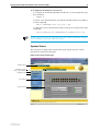
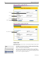
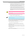
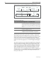
System Status
The GUI opens to display the System Status page. Figure 6 points out key
information contained on the page.
Figure 6: The System Status page
Model name
Software release
Help, Save and Exit
Sidebar menu
Port status
System status
Software Release 2.6.1
C613-02025-00 REV C
32
Rapier Switch User Guide
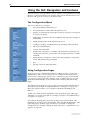
Using the GUI: Navigation and Features
The GUI consists of a large number of pages, which you navigate between using
the menu on the left of the browser window. This section describes how to use
the GUI, and gives an overview of its functionality.
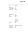
The Configuration Menu
You can use the GUI to configure:
•
the system identity and mail server
•
the system time, or NTP (Network Time Protocol)
•
triggers, to automatically run scripts at a time you specify or in response
to events you specify
•
ping polling, to monitor device reachability and respond to changes in
reachability
•
SNMP (Simple Network Management Protocol)
•
switch port settings, including mirroring, trunking and storm limits
•
802.1x port authentication
•
VLANs, STP and GARP
•
PPP dial-up connections over ISDN, and leased-line connections over
synchronous interfaces (on switches with an appropriate PIC or NSM
installed)
•
Internet Protocol: interfaces, static routes, the preferences of dynamic
routes, RIP, multicasting, and OSPF
•
IPX
•
Quality of Service and traffic filters
Using Configuration Pages
Most protocols are configured by creating or adding an entry - an IP route, a
PIM interface, and so on. For such protocols, configuration with the GUI is
based on sets of three pages: first you see a “summary” page, and from that
you access an “add” page and a “modify” page. Complex protocols are subdivided into different tabs, each with their own summary, add and modify
pages.
The summary page displays a selection table of existing items and information
about them (for example, existing PIM interfaces; see Figure 7 on page 33).
Below the selection table is a row of buttons, labelled Add, Modify and
Remove.
To add a new item, click the Add button. This opens the popup “add” page,
which lets you create a new item (for example, configure a new PIM interface;
see Figure 8 on page 34).
To modify an existing item, select it by clicking on the option button at the
beginning of its entry in the selection table. Then click the Modify button. This
opens the popup “modify” page, which lets you expand or change the
configuration (for example, change the Hello interval for a PIM interface; see
Figure 9 on page 34).
Software Release 2.6.1
C613-02025-00 REV C
Getting Started with the Graphical User Interface (GUI)
33
To delete or destroy an item, select it by clicking on the option button at the
beginning of its entry in the selection table. Then click the Remove button.
Only one person can configure a particular switch with the GUI at a time, to avoid
clashes between configurations. Monitoring and diagnostics pages can be viewed by
more than one user at a time.
Use the menus and buttons on the GUI pages to navigate, not your browser’s buttons,
to ensure that the configuration settings are saved correctly.
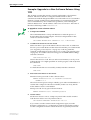
Figure 7: An example of a configuration page with a selection table
Tabs
Heading row
Radio button
Add, Modify and
Remove buttons
Software Release 2.6.1
C613-02025-00 REV C
34
Rapier Switch User Guide
Figure 8: An example of a popup “add” page
Text field
Select list
Checkbox
Apply and Cancel
buttons
Figure 9: An example of a popup “modify” page
Non-editable field
Editable Fields
GUI pages allow you to enter values or select options through a range of field
types. These include:
•
text fields, to enter character strings or numbers, especially for fields
where there are few limits on the entries (such as names). See the online
help for valid characters and field length
•
select lists, to select one option from a small number of possibilities.
Only valid options are listed. For example, if you are asked to select an
IP interface from a drop-down list, the only interfaces displayed will be
those you have assigned an IP address to
Software Release 2.6.1
C613-02025-00 REV C
Getting Started with the Graphical User Interface (GUI)
35
•
radio button lists, to choose one of a set of mutually-exclusive options
•
checkboxes, to enable or disable features.
Ports Graphic
Pages on which you can select switch ports use a Ports graphic - a visual
representation of the switch ports.To toggle through the selection options, click
on the icon representing the port you want to select or deselect.
Apply Button
An Apply button applies the configuration settings on the page or the section
of the page. The new settings will take effect immediately, but are not
automatically saved. To save the settings after clicking Apply, click the Save
button above the menu.
Cancel Button
A Cancel button closes a popup page without making any changes to the
configuration.
Close Button
A Close button closes a popup page, and conserves any changes that you made
to the settings on the page by clicking on buttons like Add, Modify, Remove or
Apply. Changes you made to editable fields will not be conserved when you
click Close (unless you first clicked Apply).
Software Release 2.6.1
C613-02025-00 REV C
36
Rapier Switch User Guide
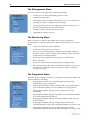
The Management Menu
You can use the GUI to manage the switch itself, including:
•
creating user accounts and enabling system security
•
creating and editing files
•
backing files up to the switch’s Flash memory or to a PC or TFTP server
•
restoring the switch’s configuration from backup
•
specifying which software and configuration files the switch uses on
bootup, and displaying the currently-used files
•
enabling software release and feature licences
•
upgrading the switch’s software
The Monitoring Menu
When you browse to the GUI, the sidebar menu opens to display the
monitoring menu, opened at the System > Status. From this menu, you can also
check:
•
information about the switch’s hardware
•
information about traffic over each port
•
the Layer 2 Forwarding Database, which shows the MAC addresses
that the switch ports have learned, and out which port the switch will
switch traffic to each MAC address
•
information about Address Resolution Protocol (ARP) entries
•
the IP route table
•
information about the state of ping polling, including counters
•
the log messages that the switch automatically generates. You can also
set up filters to determine where messages are saved to and which
messages are saved.
The Diagnostics Menu
The GUI’s diagnostics pages enable you to troubleshoot network problems and
observe traffic flow, including:
•
displaying the number of good and bad packets received and
transmitted over each switch port
•
displaying the number of frames related to 802.1x port authentication
received and transmitted over each authenticator and supplicant
•
displaying the number and type of PPP packets received and
transmitted
•
displaying the number and type of packets received and transmitted by
IP, and discarded by the IP gateway
•
displaying the number and type of ICMP and UDP packets received
and transmitted
•
displaying the number and type of RIP packets received and
transmitted; and the octets received and transmitted over each IP route
•
displaying the number and type of IPX packets received and
transmitted; and the bytes received and transmitted over each IPX route
Software Release 2.6.1
C613-02025-00 REV C
Getting Started with the Graphical User Interface (GUI)
•
displaying the contents of the switch’s file system and how much
memory is used and available. You can also delete files
•
an interface to the switch’s command line interface, allowing you to
enter CLI commands.
37
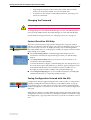
Changing the Password
As a security precaution, change the password as soon as possible.
To change the password of the default Manager account, select Management >
Users from the sidebar menu. Select the Manager account and click Modify.
For information about passwords, see “Changing a Password” on page 17.
Context Sensitive GUI Help
Help button
The GUI’s context-sensitive help system is displayed in a pop-up window
which covers the title of the GUI page. You can move the banner to any part of
your screen and/or resize it. To display the help, click on the Help button
above the sidebar menu or on the page for which you require assistance. Three
types of help are available:
■
Click General Page Info to see brief background and process flow
information. The General Page Info displays when you click the Help
button.
■
Click Page Element Info and roll your mouse over an element, to see
information about that element.
To freeze the banner’s display so that the help does not change when you
move the mouse, press the [Ctrl] key. To unfreeze, press [Ctrl] again. Note
that element information is not available for entries in tables. To see
descriptions of the columns of tables, click Complete Help Page.
■
Click Complete Help Page to see all available information, including the
element information, in a separate printable window.
Saving Configuration Entered with the GUI
Save button
Configuration changes applied using the GUI can be saved to a configuration
script by clicking the Save button at the top of the sidebar menu. A pop-up
Save window gives you the option of saving to the current configuration file,
another existing file, or a new file. You can also choose to use this configuration
at bootup.
When the Save button is red, this indicates that changes have been made to the
configuration and not yet saved. If you attempt to exit the GUI without saving
the configuration, a pop-up window will allow you to choose whether or not to
save.
Software Release 2.6.1
C613-02025-00 REV C
38
Rapier Switch User Guide
Combining GUI and CLI Configuration
You can alternate between the GUI and the CLI without difficulty. Note that
GUI pages will not automatically refresh to reflect changes in the CLI
configuration; you must reload the relevant page (for example, by clicking the
Refresh button on your browser).
Configuring Multiple Devices
If you are configuring a number of switches with similar requirements, you
may wish to:
1.
Configure one device, using either the CLI or the GUI
2.
Save that configuration. This creates a configuration file, stored in the
switch’s FLASH memory. The file consists of a sorted list of the CLI
commands that make up the configuration
3.
Upload that file to a PC, using either the CLI or the GUI
4.
Open the file in a text editor, make changes as required, and download the
file onto each switch you need to configure.
Upgrading the GUI
You can download the latest GUI resource file from the support site at
http://www.alliedtelesyn.co.nz. Before you start, ensure that the switch is running
the most recent release and patch files. The GUI is not part of the firmware
release file, but the most recent resource file will generally only be compatible
with the most recent software release. To check which files the switch is
running, refer to the “Current Install” section of the command:
SHOW INSTALL
If you are updating both the release and the resource file, set the preferred
release and restart the switch before installing the GUI as described below.
To upgrade the GUI
1.
If required, delete the old GUI resource file
If required, you can store more than one GUI resource file on the switch at
a time. If you want to delete the previous GUI resource file (for example, to
save memory), you must first disable the GUI, using the command:
DISABLE GUI
Then delete the GUI resource file, using the command:
DELETE FILE=old-gui.rsc
where:
•
old-gui.rsc is the name of the GUI resource file that you are replacing.
Wait until FLASH compaction has finished. This will take several minutes.
Do not interrupt the switch’s power supply during FLASH compaction, under
any circumstances.
Software Release 2.6.1
C613-02025-00 REV C
Getting Started with the Graphical User Interface (GUI)
39
If you have multiple valid resource files and releases stored on the switch, use the SET
INSTALL command to change the release and resource file the switch uses (see below).
2.
Load the new file onto the switch
Download the GUI resource file for your model of switch from the website
to your TFTP server. Do not rename the file.
Resource files use a fixed naming convention, which includes a product code, a language
code and a version code. For example, filenames for the Rapier 24i are of the form
dr24ie01.rsc. If you change the GUI resource file’s name, the switch will not recognise
it as a valid file and you will be unable to use it for configuration.
Load the GUI resource file from your TFTP server to the switch, using the
command:
LOAD FILE=filename.rsc SERVER=server
where:
•
filename is the name of the GUI resource file, as shown on the support
site for your switch. Do not rename the file.
•
server is the IP address of the TFTP server the file is loaded from.
When the switch has loaded the file into its RAM, it displays the message
“File transfer successfully completed”. It then writes the file to FLASH
memory, which takes approximately 30 seconds after the message. Once
the file has been copied to FLASH, you can enter commands that refer to it.
3.
Install the new file as the preferred GUI
If you are updating both the release and the resource file, set the preferred
release and restart the switch before installing the GUI as described below.
To set the new GUI resource file as the preferred resource file, use the
command:
SET INSTALL=preferred GUI=filename.rsc
You can use the GUI to load the new resource file onto the switch
(Management > Software > Upgrade), but you need to use the CLI to
install the new file.
If you disabled the GUI to delete the old resource file, enable it again, using
the command:
ENABLE GUI
Check that the new GUI resource file is valid for your device, using the
command:
SHOW GUI
If it is not, or if the file was corrupted during the download, disable the
GUI, delete the file and try again.
4.
Point your web browser at the switch’s IP address
Your browser may have a local copy of the old GUI file stored. If so, you
need to delete these temporary files (see “Deleting Temporary Files” on
page 40).
Software Release 2.6.1
C613-02025-00 REV C
40
Rapier Switch User Guide
Troubleshooting
The GUI resource file has an 8-digit name, with the file extension rsc (for
example, d_r48e03.rsc). To check which resource files are present on the
switch, use the command:
SHOW FILE
To see which GUI resource file the switch is currently using, and which it will
use on bootup, use the command:
SHOW INSTALL
To display information about the GUI resource file that is currently installed,
use the command:
SHOW GUI
In particular, this command lets you check the file’s validity. If the file is invalid
or damaged, download a new file.
To display information about the switch’s HTTP server, use the commands:
SHOW HTTP SERVER
SHOW HTTP SERVER SESSION
Deleting Temporary Files
Browsers store local copies of web pages as temporary files. If you upgrade to a
new GUI resource file, or if you encounter problems in browsing to the GUI,
you may need to delete these files (clear the cache). To clear the cache in
Internet Explorer:
1.
From the Tools menu, select Internet Options.
2.
On the General tab, click the Delete Files button.
3.
The Delete Files dialog box opens. Click the OK button.
To clear the cache in Netscape 6.2.x:
1.
From the Edit menu, select Preferences
2.
Click on the Advanced menu option to expand it.
3.
Select the Cache menu option
4.
Click the Clear Memory Cache and Clear Disk Cache buttons.
Accessing the Switch via the GUI
Problem
Diagnosis
Solution
You cannot browse to the switch.
Check if you can ping the switch’s interface from your PC. If you get a
response, this indicates that the interface’s IP address is valid, and that your PC
has a route to it.
■
If you cannot ping the switch’s interface:
•
Check that your PC’s gateway is correct, so that your PC has a route to
the switch.
Software Release 2.6.1
C613-02025-00 REV C
Getting Started with the Graphical User Interface (GUI)
41
•
The IP address of the switch’s interface may be incorrect. To correct this,
access the CLI and use the IPADDRESS parameter of command SET IP
INTERFACE
•
The IP address of the switch’s default gateway may be incorrect, so that
the switch does not have a route back to your PC’s gateway. To correct
this, access the CLI and use the NEXTHOP parameter of the command
ADD IP ROUTE or SET IP ROUTE.
■
If the switch should be dynamically assigned an IP address, check that the
DHCP server can reach the switch, by pinging the switch from the DHCP
server.
■
If your PC accesses the Internet through a proxy server, you may need to
set your browser to bypass the proxy when browsing to the switch’s IP
address range. See “HTTP Proxy Servers” on page 23 for more
information.
■
If you cannot access the GUI because your username or password fails,
check that you are spelling them correctly. The username “manager” will
always be valid. Its default password is “friend”. Note that passwords are
case sensitive.
Problem
The GUI is behaving inconsistently, or you cannot access some pages.
Solution
■
Delete your browser’s temporary files (see “Deleting Temporary Files” on
page 40) and try again.
■
Check that you are trying to access the GUI from a supported operating
system and browser combination. See “Browser and PC Setup” on page 22
for more information.
■
Check that JavaScript is enabled.
Problem
The GUI does not seem to configure the switch correctly.
Solution
■
Use the buttons on the GUI pages to navigate, not your browser’s Back,
Forward or Refresh buttons. The GUI’s navigation buttons perform aspects
of the configuration.
Traffic Flow
Problem
Solutions
No traffic is passing through the switch to or from the LAN, the DMZ or
both.
■
■
Software Release 2.6.1
C613-02025-00 REV C
Check that the switch’s link to the LAN is functioning, by checking the
interface status (Monitoring) and that the link LED is lit. If the LED is not
lit, or the appropriate interfaces do not have an status of “active”:
•
Check that the port is enabled (Configuration > Port > Settings)
•
Check that the IP address of the interface is still valid.
•
Check that the cables are connected correctly and function correctly.
Check the RIP configuration (Configuration > Internet Protocol > RIP).
•
Check that the RIP neighbour can reach the switch, by pinging the
switch from the RIP neighbour.
•
Any password and authentication settings must be configured on the
neighbour as well as on this switch.
42
Rapier Switch User Guide
■
Check that the switch is passing the correct DNS information to hosts on
the LAN, if the switch is a DHCP server. If the switch acting as a DHCP
client as well, and therefore is passing on DNS information from another
DHCP server, check that this DHCP server is providing the switch with the
correct information.
IP Addresses and DHCP
Problem
The switch is enabled as a DHCP server, but cannot assign an IP address to a
host.
Solution
■
Reboot the host machine.
■
Check the host’s TCP/IP settings, to make sure that the host is set to obtain
its IP address dynamically:
In Windows 95/98, click Settings > Control Panel > Network. Select TCP/
IP and click Properties. Click Obtain an IP address automatically.
In Windows 2000, click Settings > Control Panel > Network and Dial-up
Connections > Local Area Connection > Properties. Select Internet
connection (TCP/IP) and click Properties. Click Obtain an IP address
automatically.
■
Check that the switch’s link to the LAN is functioning, by checking the
interface status (Monitoring) and that the link LED is lit (see “Traffic Flow”
on page 41).
Time and NTP
Diagnosis
The switch’s time is displayed on the Configuration > System > Time tab. It
will also be included in log packets.
Problem
The switch’s time does not change, even though you entered the correct time.
Solution
Changing the time is a 3-step process. Select Configuration > System > Time.
First, enter a time that is very shortly in the future (e.g. 20 seconds later than
the current time). Then check Set time. Then wait until precisely the time you
have entered, and click Apply.
Problem
The switch is not assigning the time to devices on the LAN.
Solutions
■
Check NTP is enabled (Configuration > System > Time).
■
Check that the NTP peer’s IP address is entered correctly.
■
Check that the NTP peer can reach the switch, by pinging the switch from
the NTP peer.
■
Check that the switch’s link to the LAN is functioning. See “Traffic Flow” on
page 41.
Problem
The switch’s clock does not synchronise with the NTP peer.
Solution
■
The switch’s clock can only synchronise with the NTP peer if its initial time
is similar to the NTP peer’s time (after setting the UTC offset). Manually
set the switch’s time so that it is approximately correct, and enable NTP
again.
■
Check that the UTC offset is correct.
Software Release 2.6.1
C613-02025-00 REV C
Getting Started with the Graphical User Interface (GUI)
43
Problem
The switch’s time is incorrect, even though it assigns the correct time to
devices on the LAN.
Solution
The UTC offset is probably incorrect, or needs to be adjusted for the beginning
or end of summer time. To correct this, select Configuration > System > Time
and enter the correct offset.
Loading Software
Problem
You have attempted to load a new release file onto the switch, but the load
has failed and you cannot access the switch through the GUI.
Solution
1.
Access the switch’s CLI (see “Connecting a Terminal or PC” on page 14).
If the switch has been switched off or has rebooted since you attempted to
load the release file, it will boot up with the default installation. This
contains the commands you require to load a file.
Log into the switch using the manager account and password.
2.
Software Release 2.6.1
C613-02025-00 REV C
Download the release file to the switch. See “Example: Upgrade to a New
Software Release Using TFTP” on page 59 for an example.
Chapter 4
Operating the switch
This Chapter
This chapter introduces basic operations on the switch, including:
■
“User Accounts and Privileges” on page 45
■
“Normal Mode and Security Mode” on page 47
■
“Remote Management” on page 50
■
“Storing Files in FLASH Memory” on page 51
■
“Using Scripts” on page 52
■
“Loading and Uploading Files” on page 53
■
“Upgrading Switch Software” on page 57
■
“Using the Built-in Editor” on page 61
■
“SNMP and MIBs” on page 62
User Accounts and Privileges
The switch software supports three levels of privilege for users: USER,
MANAGER, and SECURITY OFFICER. By default, the switch has one account
(manager) defined with manager privilege and the default password friend. The
commands that a user can execute depends on the user’s privilege level and
whether the switch is operating in normal or security mode (see “Normal Mode
and Security Mode” on page 47). A USER level prompt looks like:
>
while a MANAGER prompt looks like:
Manager >
and a SECURITY OFFICER prompt looks like:
SecOff >
The MANAGER level has access to the full set of commands when the switch is
in normal mode. When the switch is operating in security mode, users with
MANAGER privilege cannot execute a subset of the commands known as the
security commands (see “Normal Mode and Security Mode” on page 47).
46
Rapier Switch User Guide
In normal mode, a user with manager privilege can create and delete accounts
for users with any of these privilege levels. Users and passwords are managed
by the User Authentication Facility. Users and passwords are authenticated
using an internal database called the User Authentication Database, or by
interrogation of external RADIUS (Remote Authentication Dial In User Service) or
TACACS (Terminal Access Controller Access System) servers.
On the CLI, to use an account with manager privilege, log in to the account by
entering the command:
LOGIN
The switch prompts you to enter a user name and password. To return to USER
mode, enter the command:
LOGOFF
Make sure that you do not leave a manager session unattended. Unauthorised
use of a manager session gives access to the User Authentication Database. To
reduce the risk of unauthorised activity, a subset of manager commands have a
security timer. These commands are shown in Table 4 on page 46. When you
enter one of these commands from a manager session, the security timer is
started and is then restarted each time you enter another of these commands. If
you enter one of these commands after the timer has expired, you are
prompted to re-enter the password. The secure delay timer is by default 60
seconds. If the password is not entered correctly the password prompt is
repeated a set number of times. If the correct password is still not entered a log
message is generated and the session is logged off.
The security timer enables a manager to make successive additions and
modifications to the database at one time without having to re-enter the
password for every command.
The security timer does not provide a foolproof security mechanism. Managers
should always attempt to log out of a manager session before leaving a
terminal unattended.
Table 4: Secure commands controlled by the security timer.
Command
Description
ADD TACACS SERVER
Adds a TACACS server to the list of TACACS servers used
for user authentication.
ADD USER
Adds a user to the User Authentication Database.
DELETE TACACS SERVER
Deletes a TACACS server from the list of TACACS servers
used for user authentication.
DELETE USER
Deletes a user from the User Authentication Database.
PURGE USER
Deletes all users except MANAGER from the User
Authentication Database.
SET MANAGER PORT
Assigns a port semipermanent MANAGER privilege.
SET USER
Modifies a user record in the User Authentication Database.
If the switch is operating in security mode, the manager must also log in to a user
account with SECURITY OFFICER privilege in order to execute any of the commands
listed in Table 4 on page 46.
Software Release 2.6.1
C613-02025-00 REV C
Operating the switch
47
See the Operations chapter in the Rapier Series Switch Software Reference for:
■
More information about managing and using accounts with user, manager
and security officer privileges
■
A full list of commands that require security officer privilege when the
switch is in secure mode
■
Information about enabling a remote security officer.
Normal Mode and Security Mode
The switch operates in one of two modes, either normal mode or security
mode. By default, the switch is in normal mode.
When the switch is in security mode, the command SHOW DEBUG does not display
output of the SHOW FEATURE and SHOW CONFIGURATION DYNAMIC
commands, or the current configuration in the SHOW SYSTEM output unless the
SHOW DEBUG command is entered by a user with security officer privilege.
If you wish to use the following software features you need to enable security
mode:
■
IP authentication
■
Secure Shell (see the Secure Shell chapter, Rapier Series Switch Software
Reference)
■
Encryption (see the Compression and Encryption Services chapter, Rapier
Series Switch Software Reference)
■
IPsec (see the IP Security chapter, Rapier Series Switch Software Reference)
■
Public Key Encryption (PKI) (see the Public Key Infrastructure chapter,
Rapier Series Switch Software Reference)
■
Secure Sockets Layer (SSL) (see the Secure Sockets Layer chapter, Rapier
Series Switch Software Reference)
To enable security mode, first create a user with security officer privilege, then
enter the command:
ENABLE SYSTEM SECURITY_MODE
To access secure functionality you will need to log in again as the security
officer.
When the switch restarts, it restarts in the same normal mode or security mode
as it was before restarting. To restore the switch to normal operating mode,
enter the command:
DISABLE SYSTEM SECURITY_MODE
When security mode is disabled, the switch automatically deletes all sensitive
data files, including encryption keys.
To display the current operating mode, enter the command:
SHOW SYSTEM
Software Release 2.6.1
C613-02025-00 REV C
48
Rapier Switch User Guide
When the switch is in security mode, a user with security officer privilege is the
only person who can execute commands which affect switch security. Table 5
on page 48 lists commands that only a security officer can execute when the
switch is in security mode. A complete list of commands limited by security
mode are listed in the Operation chapter in the Rapier Series Switch Software
Reference.
Table 5: Commands requiring SECURITY OFFICER privilege when the switch is
operating in security mode .
Command
Specific Parameters
ACTIVATE IPSEC
ACTIVATE SCR
ADD FR DLC
ENCRYPTION
ADD IP INT
ADD IP SA
ADD PKI
ADD SA
ADD SCR
ADD SSH
ADD USER
CLEAR NVS TOTALLY
CREATE CONFIG
CREATE ENCO KEY
CREATE FR
DEFENCRYPTION
CREATE IPSEC
CREATE ISAKMP
CREATE PKI
CREATE PPP
CREATE PPP TEMPLATE
CREATE SA
CREATE SNMP COMMUNITY
CREATE STAR
DEACTIVATE SCR
DELETE FILE
DELELTE IP SA
DELETE NVS
DELETE PKI
DELETE SA
DELETE SCR
DELETE SSH
DELETE USER
DESTROY ENCO KEY
DESTROY IPSEC
DESTROY ISAKMP
DESTROY PKI
Software Release 2.6.1
C613-02025-00 REV C
Operating the switch
49
Table 5: Commands requiring SECURITY OFFICER privilege when the switch is
operating in security mode (Continued).
Command
Specific Parameters
DESTROY SA
DESTROY STAR
DISABLE FEATURE
DISABLE IPSEC
DISABLE ISAKMP
DISABLE PKI DEBUG
DISABLE SA
DISABLE SSH
DISABLE USER
DUMP
EDIT
ENABLE FEATURE
ENABLE IPSEC
ENABLE ISAKMP
ENABLE PKI DEBUG
ENABLE PPP DEBUG
ENABLE PPP TEMPLATE DEBUG
ENABLE SA
ENABLE SNMP
ENABLE SSH
ENABLE STAR
MKTTRANSFER
ENABLE USER
LOAD
MAIL
MODIFY
PURGE IPSEC
PURGE PKI
PURGE USER
RENAME FILE
RESET ENCO
RESET IPSEC
RESET USER
SET CONFIG
SET ENCO KEY
SET FR
SET INSTALL
SET IP INT
SET IPSEC
SET PKI
SET PPP
Software Release 2.6.1
C613-02025-00 REV C
ENCRYPTION, DEFENCRYPTION
50
Rapier Switch User Guide
Table 5: Commands requiring SECURITY OFFICER privilege when the switch is
operating in security mode (Continued).
Command
Specific Parameters
SET PPP TEMPLATE
SET SA
SET SCR
SET SNMP COMMUNITY
SET SSH
SET STAR
SET USER
SHOW CONFIG
SHOW ENCO KEY
SHOW FEATURE
SHOW FILE
SHOW NVS
SHOW PPP
CONFIG
SHOW STAR
[=id], MKTTRANSFER, NETKEY
UPLOAD
Remote Management
You can manage remote switches as easily as you manage the local switch a
terminal is connected to. From a terminal connected to any port (with either
USER or MANAGER privilege), enter the command:
TELNET ipadd
to Telnet to the remote switch, specifying the remote router’s IP address.
switchFor information about how to set routes and on how you assign an IP
address to your switch, see “Setting Routes” on page 16 and “Assigning an IP
Address” on page 15.
If the connection is successful, a login prompt from the remote switch is
displayed. Login using a login name that has been defined with MANAGER
privilege (such as the default MANAGER login name), and enter the
password.
To return to the local switch and terminate the connection, enter the command:
LOGOFF
For more information about using Telnet, see the Terminal Server chapter in the
Rapier Series Switch Software Reference.
Software Release 2.6.1
C613-02025-00 REV C
Operating the switch
51
Storing Files in FLASH Memory
When you purchase the switch, the switch software release, the online help
files, and a default configuration file are stored in FLASH memory, where they
are saved even if the switch is powered down. You will use the FLASH
memory to store updated software releases or patches, and files that record the
router’s configuration. FLASH memory is like a flat file system, with no
subdirectories.
The switch also has Random Access Memory (RAM). The switch software uses
RAM to run the switch. When you enter commands to configure the switch
these commands affect the dynamic configuration in RAM.
FLASH memory is like a flat file system, with no subdirectories.
File names of up to 16 characters long, with extensions of 3 characters (DOS
16.3 format), are supported on the switch. However, files on the switch are
stored in FLASH using the DOS 8.3 format of 8 characters long, with
extensions of 3 characters. For example, the file extralongfilenam.cfg may
be saved as extral~1.cfg in the FLASH File System. Therefore, files can be
accessed via two file names, either of which can be used for file management.
A translation table, named longname.lfn, converts file names between DOS
16.3 format and DOS 8.3 format. To reconcile file names the switch consults the
translation table which is synchronised with file contents in memory. For more
information about working with files see the Working With Files section,
Operation chapter, Rapier Series Switch Software Reference.
To display the files in FLASH, enter the command:
SHOW FILE
Figure 10: Example output from the SHOW FILE command.
Filename
Device
Size
Created
Locks
---------------------------------------------------------------------------28-72.pat
flash
111764
05-May-1997 12:41:42
0
28-74ang.rel
flash
2013756 09-May-1997 15:58:55
0
28f72-06.pat
flash
123268
18-Apr-1997 15:58:16
0
release.lic
flash
32
08-May-1997 16:43:49
0
test.cfg
flash
1698
09-May-1997 10:39:42
0
sixteenalongfile.scp
flash
24
30-May-1997 15:10:12
0
----------------------------------------------------------------------------
The Locks field indicates the number of concurrent software processes using the file.
The switch automatically compacts FLASH memory when a maximum
threshold of deleted files is reached. Compaction frees space for new files by
discarding garbage. A message will appear when FLASH compaction is
activated. Another message appears when FLASH compaction is complete.
While FLASH is compacting, do not restart the switch or use any commands
that affect the FLASH file subsystem. Do not restart the switch, or create, edit,
load, rename or delete any files until a message confirms that FLASH file
compaction is completed. Interrupting flash compaction may result in damage
to files.
Software Release 2.6.1
C613-02025-00 REV C
52
Rapier Switch User Guide
Using Scripts
When you start or restart the switch, or when it automatically restarts, it
executes the configuration commands in the boot script. A boot script is a text
file containing a sequence of standard commands that the switch executes at
startup. The default boot script is called boot.cfg. Commands run from a boot
script are limited to 128 characters.
The commands you enter into the switch from the command line affect only
the dynamic configuration in RAM, which is not retained over a power cycle.
The switch does not automatically store these changes in FLASH memory.
When the switch is restarted, it loads the configuration defined by the boot
script, or if the switch was restarted using the RESTART command, any script
file specified in the RESTART command.
In addition to the boot configuration script that the switch automatically runs
when it restarts, you can run a configuration script manually at any time, by
entering the command:
ACTIVATE SCRIPT=filename
You can also set a trigger to automatically execute a configuration script when
a specified event occurs.
For more information about how to create and run scripts, see the Scripting
chapter in the Rapier Series Switch Software Reference.
For information about creating triggers, see the Trigger Facility chapter in the
Rapier Series Switch Software Reference.
Saving the Switch’s Configuration
To view the router’s current dynamic configuration, enter the command:
SHOW CONFIGURATION DYNAMIC
To save any changes made to the dynamic configuration after the switch last
restarted (booted) across a restart or power cycle, and save the modified
configuration as a script file, enter the command:
CREATE CONFIG=filename.scp
To set the switch to execute this script file when it restarts, enter the command:
SET CONFIG=filename.scp
The configuration file created by CREATE CONFIG command records passwords in
encrypted form, not in cleartext.
You can create a script file from any of the switch software commands. These
are the same commands that are used to change the router’s configuration
dynamically. Manually edit a configuration file using the router’s built in
editor (see “Using the Built-in Editor” on page 61), or upload it to a PC using the
UPLOAD command (see the Operation chapter, Rapier Series Switch Software
Reference), edit it using any text editor, and download it again. Give
configuration script files an extension of .scp or .cfg.
To display the name of the configuration file that is set to execute when the
switch restarts, enter the command:
SHOW CONFIG=filename
Software Release 2.6.1
C613-02025-00 REV C
Operating the switch
53
Storing Multiple Scripts
You can store multiple configuration scripts on the switch. This allows you to
test new configuration scripts once, before setting them as the default
configuration. For example, to test the new configuration script test.cfg,
enter the command:
RESTART SWITCH CONFIG=test.cfg
Storing multiple scripts also allows you to keep a backup switch with
configuration scripts stored on it for every switch in the network to speed up
network recovery time.
Loading and Uploading Files
When you want to upgrade your switch to a new software patch or release, or
use a new configuration file, load files onto the switch using the router’s
LOADER module. You can also use the LOADER module to upload files, such
as configuration files or log files, from the switch onto a host on the network.
File Naming Conventions
The file subsystem provides a flat file system—directories are not supported.
Files are uniquely identified by a file name of the form:
[device:]filename.ext
where:
■
device specifies the physical memory device on which the file is stored,
FLASH. If device is specified, it must be separated from the rest of the file
name by a colon (“:”). device is optional. If device is not specified, the default
is FLASH.
■
filename is a descriptive name for the file, and may be one to eight
characters in length. Valid characters are lowercase letters (a–z), uppercase
letters (A–Z), digits (0–9) and the hyphen character (-).
■
ext is a file name extension, one to three characters in length. Some file
name extensions are shown in Figure 6 on page 53. Valid characters are
lowercase letters (a–z), uppercase letters (A–Z), digits (0–9) and the hyphen
character (-). The extension is used by the switch to determine the data
type of the file and how to use the file (Table 6 on page 53). If ext is
specified, it must be separated from the filename portion by a period (“.”)
Table 6: File extensions and file types .
Software Release 2.6.1
C613-02025-00 REV C
Extension
File type/function
CER
Public Key Infrastructure (PKI) certificate file.
CFG
Configuration or boot script.
CRL
PKI Certificate Revocation List file.
CSR
PKI Certificate Signing Request file.
GIF
(Graphics Interchange Format) graphic image file.
HLP
CLI help file.
HTM
HTML file used by the HTTP server.
54
Rapier Switch User Guide
Table 6: File extensions and file types (Continued).
Extension
File type/function
INS
Stores install information created by using the SET INSTALL
command.
JPG
(Joint Photographic Experts Group) graphic image file.
KEY
Public portion of an RSA key.
LIC
Licence information.
LOG
Log file.
MDS
Modem script.
PAT
Patch.
PAZ
Compressed patch.
REL
Software release.
REZ
Compressed release.
SCP
Script.
SPA
Spam Mail Source files, listing email addresses, identified as spam
mail sources, to be blocked by the firewall SMTP proxy, if it is
active.
SPL
VPN client.
TXT
Generic text file.
VPF
Future VPN client.
LFN
Extension used for the long file name translation table
You may see files on your switch with file name extensions not listed in Table 6
on page 53. If you require more information about file types and file name
extensions, contact your authorised distributor or reseller.
Do not change the header in a release or patch file. At best, this will cause the
file load or install to fail, at worst the switch could be put into a state where it
will not boot correctly until field service action is taken.
Loading Files
The LOADER module is responsible for loading and storing releases, patches,
PKI certificates and other files into FLASH. The LOADER module uses the
Trivial File Transfer Protocol (TFTP), Hypertext Transfer Protocol (HTTP), or
ZMODEM over an asynchronous port, to retrieve files from a network host.
You can also load text files without using any of these protocols. For
information about using Lightweight Directory Access Protocol (LDAP) to
load PKI certificates or certificate revocation lists (CRLs), see the Operation
chapter in the Rapier Series Switch Software Reference.
The router’s default download method is TFTP. To load a file onto the switch
from a TFTP server using the TFTP protocol, enter the command:
LOAD [METHOD=TFTP] [DELAY=delay] [DESTFILE=destfilename]
[DESTINATION={BOOTBLOCK|FLASH}] [SERVER={hostname|ipadd}]
[SRCFILE|FILE=filename]
Software Release 2.6.1
C613-02025-00 REV C
Operating the switch
55
To load a file onto the switch using the HTTP protocol, enter the command:
LOAD [METHOD={HTTP|WEB|WWW}] [DELAY=delay]
[DESTFILE=destfilename] [DESTINATION=BOOTBLOCK|FLASH}]
[HTTPPROXY={hostname|ipadd} [PASSWORD=password]
[PROXYPORT=1..65535]] [SERVER={hostname|ipadd}]
[SERVPORT={1..65535|DEFAULT}] [SRCFILE|FILE=filename]
[USERNAME=username]
The switch can only load one file at a time. Wait for the current transfer to
complete before initiating another transfer. To display the default configuration
of the LOADER module, and the progress of any current transfer, enter the
command:
SHOW LOADER
To stop a load at any time, leaving the LOADER module ready to load again,
enter the command:
RESET LOADER
Setting LOADER Defaults
You are likely to repeat the process of downloading files onto the switch using
a similar method each time. You can set defaults for some or all of the LOADER
parameters. You can then use or override some or all of these defaults for each
particular load.
To set LOADER defaults, enter the command:
SET LOADER [ATTRIBUTE={CERT|CRL|CACERT|DEFAULT}]
[BASEOBJECT={dist-name|DEFAULT}] [DELAY={delay|DEFAULT}]
[DESTFILE=dest-filename] [DESTINATION={FLASH|DEFAULT}]
[HTTPPROXY={hostname|ipadd|DEFAULT}]
[METHOD={HTTP|LDAP|TFTP|WEB|WWW|ZMODEM|NONE|DEFAULT}]
[PASSWORD=password] [PROXYPORT={1..65535|DEFAULT}]
[{SCRFILE|FILE}=filename]
[SERVER={host-name|ipadd|DEFAULT}]
[SERVPORT={1..65535|DEFAULT}] [USERNAME=username]
You can set all parameters except DESTFILE, SCRFILE and FILE back to the
factory defaults with the option DEFAULT.
For more information about setting the LOADER defaults on your switch, see
the Operations chapter in the Rapier Series Switch Software Reference.
Example: Load a Patch File Using HTTP
This example loads a patch file onto the switch from an HTTP server on the
network. Before following this procedure, make sure:
Software Release 2.6.1
C613-02025-00 REV C
■
The HTTP server is operating on a host with an IP address (for example
192.168.1.1) on the network, and that the patch file is in the server’s HTTP
directory.
■
The switch has an IP address (for example 192.168.1.2) on the interface
connecting it to the HTTP server, and that it can communicate with the
server.
■
There is enough space in the router’s FLASH for the new patch file.
56
Rapier Switch User Guide
To load a patch file
1.
Configure the LOADER.
Set the LOADER module with defaults to make the process of
downloading files in future simpler.
SET LOADER METHOD=HTTP SERVER=192.168.1.1
DESTINATION=FLASH
2.
Download the patch file.
Download the patch file onto the switch, using the defaults set above.
LOAD FILE=86251-01.paz
When the download has completed, check that the file is in FLASH.
SHOW FILE
This shows the file 86251-01.paz is present.
To activate the patch see “To upgrade to a new patch file:” on page 60.
Uploading Files From the Switch
The LOADER can upload files from the switch to a network host, using TFTP
or ZMODEM. Upload files using one of the commands:
UPLOAD [METHOD=TFTP] [FILE=filename]
[SERVER={hostname|ipadd}]
UPLOAD [METHOD=ZMODEM] [FILE=filename] [ASYN=port]
The UPLOAD command uses defaults set with the SET LOADER command,
for parameters not specified with the upload command.
You can install Allied Telesyn’s Trivial File Transfer Protocol Server (AT-TFTP
Server) on any PC or server running Windows. This will provide a simple way
to make files available to all Allied Telesyn routers and layer 3 switches in your
network. The TFTP Server, and a readme file describing how to install and use
it, are provided on the Rapier Series Switch Documentation and Tools CD-ROM.
Example: Upload a Configuration File Using TFTP
This example uploads a configuration file from the switch to a TFTP server on
the network. Before following this procedure, make sure:
■
The TFTP server is operating on a host with an IP address (for example
192.168.1.3) on the network.
■
The switch has a valid IP address (for example 192.168.1.2) on the interface
connecting it to the TFTP server, and that it can communicate with the
server.
■
The configuration file is present in the router’s FLASH.
To upload a log file:
1.
Configure the LOADER.
Set the LOADER module with defaults to make the process of
downloading and uploading files in future simpler.
SET LOADER METHOD=TFTP SERVER=192.168.1.3
Software Release 2.6.1
C613-02025-00 REV C
Operating the switch
57
2.
Upload the configuration file.
Upload the configuration file from the switch into the TFTP directory of the
TFTP server on the network, using the defaults set above.
UPLOAD FILE=filename.cfg
Monitor the load progress.
SHOW LOAD
When the upload is complete, check that the file is in the TFTP directory on
the network host.
More information
For more information about loading files onto and uploading files from the
switch, including using LDAP to load PKI certificate information, see the
Operation chapter in the Rapier Series Switch Software Reference.
Upgrading Switch Software
When you first start the switch, it automatically loads the software release from
FLASH memory into RAM, where the CPU uses it to run all the router’s
software features. The switch may also load a patch file to improve the main
release. The software release and any patch files are current when the switch is
produced at the factory.
When Allied Telesyn makes a new patch or release available, you may want to
upgrade the software on your switch to use a new patch or release file. You can
download the latest software patches, full software releases, and CLI help files
from the support site at: http://www.alliedtelesyn.co.nz/support/rapier.
Make sure you download a patch or release file that matches your switch
model. A patch or release file for Rapier Series Switch has 86 as the first two
digits of the filename. Patch files have the file extension .paz and release files
have the file extension .rez. For example, the Software Release 2.6.1 for the
Rapier Series Switch has the filename 86s-261.rez.
Release and patch files are compressed ASCII files, and consist of a header
followed by a sequence of Motorola S-records containing the actual code for
the release or patch. The header has a standard format, which provides
information about the release or patch to the switch.
Do not change the header in a release or patch file. At best, this will cause the
file load or install to fail, at worst the switch could be put into a state where it
will not boot correctly until field service action is taken.
The current release and patch file are set as the preferred install. The switch
also has a very limited version of the software stored in EPROM. You cannot
delete this version as it is the default, or boot install. When you load a new
software release or patch, you can set it to run once, the next time the switch
reboots. This temporary install allows you to test run a new release or patch
once, before you make it the preferred install. If the temporary install fails the
switch will automatically run the preferred install if there is one, or otherwise
the default install, the next time the switch reboots.
Software Release 2.6.1
C613-02025-00 REV C
58
Rapier Switch User Guide
When the switch reboots, it checks the install information in a strict order:
•
Firstly, the switch checks the temporary install. If a temporary install is
specified, the switch loads it into RAM and runs it. At the same time, it
deletes the temporary install information so it will not load a second
time. This information is deleted even if the temporary install triggers a
fatal condition causing the switch to reboot immediately.
•
Secondly, if no temporary install is defined, or the install information is
invalid, the switch checks the preferred install. If present, this install is
loaded. The switch never deletes the preferred install information.
•
Thirdly, if neither a temporary install nor a preferred install is specified,
the switch loads the default install. The default install is always present
in the switch because if, for some reason, it is not, the INSTALL module
will restore it.
The preferred install should not be set up with an untested release or patch. It
is advisable to install new releases or patches as the temporary install, and
when the switch boots correctly, to then set up the preferred install with the
new release or patch.
To change the install information in the switch, enter the command:
SET INSTALL={TEMPORARY|PREFERRED|DEFAULT}
[RELEASE={release-name|EPROM}] [PATCH=patch-name]
For security reasons the SET INSTALL command is only accepted if the user has
SECURITY OFFICER privilege.
When you set a patch file as part of a temporary install or permanent install,
you must also set the corresponding release file in the same command, if it has
not already been set as part of that install. You can set the patch, but not the
release (always EPROM), for the default install.
To delete a temporary install or preferred install, enter the command:
DELETE INSTALL={TEMPORARY|PREFERRED}
If a default install is set, only the patch information is deleted using the
DELETE INSTALL command as the release information must always be left
intact in the default install.
To display the current install information, including which install is currently
running in the switch, and how the install information was checked at the last
reboot, enter the command:
SHOW INSTALL
For more information about INSTALL commands, see the Operations chapter in
the Rapier Series Switch Software Reference.
Software Release 2.6.1
C613-02025-00 REV C
Operating the switch
59
Example: Upgrade to a New Software Release Using
TFTP
This example assumes the switch is correctly configured to allow TFTP to
function. This means that IP is configured and the switch is able to
communicate with the designated TFTP server. The TFTP server is assumed to
function correctly and the release and patch files are assumed present in the
server’s TFTP directory. The switch has no patch files, and is running the
Software Release 2.6.1. The IP address of the server is 172.16.1.1. The name of
the release file being loaded is 86s-262.rez.
To upgrade to a new software release:
1.
Configure the LOADER.
The LOADER module is set up with defaults to make the process of
downloading files in future simpler. All release and patch files in this
switch are stored in FLASH.
SET LOADER METHOD=TFTP SERVER=172.16.1.1 DEST=FLASH
2.
Load the new release file onto the switch.
Make sure there is space in FLASH for the new release file. Load the new
file onto your switch. Make sure the release file matches your switch model
(see “Upgrading Switch Software” on page 57). Load any patch files
required, and the help file for the release (see “Loading and Uploading Files”
on page 53). To load the release file using your LOADER default settings,
enter the command:
LOAD FILE=86s-262.rez
Wait for the release to load. This can take several minutes, even if you are
loading the file over a high speed link. To see the progress of the load, enter
the command:
SHOW LOAD
To check that the files are successfully loaded, enter the command:
SHOW FILE
3.
Enter licence information for the release.
Enter the licence password for the software release.
ENABLE RELEASE=86s-262.rez PASSWORD=ce645398fbe
NUMBER=2.6.2
The release licence password is provided by your authorised distributor or
reseller and is unique for the release number (in this case 2.6.2), the file
name and the router’s serial number.
Enter passwords for any special feature licences.
ENABLE FEATURE=feature PASSWORD=password
4.
Test the release.
Set the new release to run as a temporary install. This sets the switch to
load the new release once only when it reboots.
SET INSTALL=TEMPORARY RELEASE=86s-262.rez
If you want to use the current switch configuration again, store the
dynamic configuration as a configuration script file and set the switch to
use this configuration when it restarts. Releases are generally backward-
Software Release 2.6.1
C613-02025-00 REV C
60
Rapier Switch User Guide
compatible, so your current configuration should run with little or no
modifications on the later release.
CREATE CONFIG=myconfig.cfg
SET CONFIG=myconfig.cfg
The SET CONFIG information survives the release update.
Reboot the switch.
RESTART REBOOT
The switch reboots, loading the new release file and the specified
configuration. Display the install history, and check that the temporary
release was loaded.
SHOW INSTALL
5.
Make the release the default (permanent) release.
If the switch operates correctly with the new release, make the release
permanent.
SET INSTALL=PREFERRED RELEASE=86s-262.rez
Every time the switch reboots from now on, it loads the new release from
FLASH.
Example: Upgrade to a new patch file
Use this procedure to upgrade the software release currently running on the
switch with a new patch. This example assumes that the current release,
Software Release 2.6.1, is set as the preferred release.
To upgrade to a new patch file:
1.
Load the new patch file onto the switch.
Load the new file onto your switch. See “Loading and Uploading Files” on
page 53.
LOAD FILE=86261-01.paz
Check that the file is successfully loaded.
SHOW FILE
2.
Test the patch.
Set the release to run as a temporary install, so that it loads the patch once
only the next time it reboots.
SET INSTALL=TEMPORARY RELEASE=86s-261.rez
PATCH=86261-01.paz
If you want to use the current switch configuration again, store the
dynamic configuration as a configuration script file, and set the switch to
use this configuration when it restarts.
CREATE CONFIG=myconfig.scp
SET CONFIG=myconfig.scp
Reboot the switch.
RESTART REBOOT
Software Release 2.6.1
C613-02025-00 REV C
Operating the switch
61
The switch reboots, loading the new patch file and the specified
configuration. Check that the switch operates correctly with the new patch
file.
3.
Make the patch part of the default (permanent) release.
If the switch operates correctly with the new patch, make the release
permanent.
SET INSTALL=PREFERRED RELEASE=86s-261.rez
PATCH=86261-01.paz
Every time the switch reboots from now on, it loads the new release and
patch from FLASH.
Do not set an untested patch as part of the preferred install.
Using the Built-in Editor
The Rapier Series Switch has a built-in full-screen text editor for editing script
files stored on the switch file subsystem. Using the text editor you can run
script files manually, or set script files to run automatically at switch restart, or
on trigger events. Figure 11 on page 61 shows a example screen shot of the text
editor. To start the editor with a new file or an existing file, enter the command:
EDIT [filename]
Figure 11: The editor screen layout.
The editor uses VT100 command sequences and should only be used with a
VT100-compatible terminal, terminal emulation program or Telnet client.
To display editor Help at any time while in the editor press [Ctrl/K,H]; that is,
hold down the Ctrl key and press in turn the K key then the H key.
For more information about the inbuilt editor, see the Operation chapter in the
Rapier Series Switch Software Reference.
Software Release 2.6.1
C613-02025-00 REV C
62
Rapier Switch User Guide
SNMP and MIBs
You can remotely monitor some features of the switch using Simple Network
Management Protocol (SNMP).
For information about the MIBs supported by the switch, see Appendix C:
SNMP MIBs in the Rapier Series Switch Software Reference.
The SNMP agent is disabled by default. To enable SNMP, enter the command:
ENABLE SNMP
SNMP communities are the main configuration item in the router’s SNMP
agent, and are defined in terms of a list of IP addresses which define the SNMP
application entities (trap hosts and management stations) in the community. To
create an SNMP community, enter the command:
CREATE SNMP COMMUNITY=name [ACCESS={READ|WRITE}]
[TRAPHOST=ipadd] [MANAGER=ipadd]
[OPEN={ON|OFF|YES|NO|TRUE|FALSE}]
The community name is a security feature and you should keep it secure.
To enable the generation of authentication failure traps by the SNMP agent
whenever an SNMP authentication failure occurs, enter the command:
ENABLE SNMP AUTHENTICATE_TRAP
To enable the generation of link state traps for a specified interface, enter the
command:
ENABLE INTERFACE=interface LINKTRAP
where interface is the name of an interface, such as “vlan11”.
For more information see the Simple Network Management Protocol (SNMP)
chapter and the Interfaces chapter in the Rapier Series Switch Software Reference.
To display the current state and configuration of the SNMP agent, enter the
command:
SHOW SNMP
For a detailed description of the output from the SHOW SNMP command, see
the Simple Network Management Protocol (SNMP) chapter in the Rapier Series
Switch Software Reference.
For More About Operations and Facilities
For more detail about operating the switch, and for full command syntax
definitions, see the Operation chapter in the Rapier Series Switch Software
Reference, including:
■
How to use the User Authentication Facility, RADIUS, TACACs or
TACACS+ for authenticating users who log on to the switch, and ensuring
that only authorised login accounts are used.
■
How to use the HTTP Client, which you can use to download software files
onto the switch, and the HTTP Server.
■
How to use the Mail Subsystem.
Software Release 2.6.1
C613-02025-00 REV C
Operating the switch
63
■
How to use LDAP to load PKI certificates and CRLs onto your switch.
■
Switch Startup Operations
■
How to use FLASH compaction to regain storage space on the switch. Read
“Warning about FLASH memory” on page 12 before you attempt to do this.
■
How to set aliases to represent common command strings.
■
How to define a remote security officer, so you can manage the security
features remotely via Telnet.
See other chapters in the Rapier Series Switch Software Reference for more
information on how to:
Software Release 2.6.1
C613-02025-00 REV C
■
Use the logging facility to monitor network activity and to select and
display the results (see the Logging Facility chapter).
■
Use SNMP to manage the switch remotely (see the Simple Network
Management Protocol (SNMP) chapter and Appendix C: SNMP MIBs).
■
Use the command line to create, delete and modify configuration scripts
(see the Scripting chapter).
■
Set up triggers to automatically run specified scripts at specified times, or
at specified events (see the Trigger Facility chapter).
■
Use NTP to synchronise your router’s time clock with those of other
network devices (see the Network Time Protocol (NTP) chapter).
■
Use software to test whether the router’s hardware functions correctly (see
the Test Facility chapter).
Layer 2 Switching
65
Chapter 5
Layer 2 Switching
This section describes the Layer 2 switching features on the Rapier Series
Switch, and how to configure them.
Switch Ports
Each Ethernet switch port is uniquely identified by a port number. The switch
supports a number of features at the physical level that allow it to be connected
in a variety of physical networks. This physical layer (layer 1) versatility
includes:
■
Enabling and disabling of Ethernet ports.
■
Auto negotiation of port speed and duplex mode for all 10/100 Ethernet
ports.
■
Manual setting of port speed and duplex mode for all 10/100 Ethernet
ports.
■
Link up and link down triggers.
■
Port trunking.
■
Packet storm protection.
■
Port mirroring.
■
Support for SNMP management
Enabling and Disabling Switch Ports
An switch port that is enabled is available for packet reception and
transmission. Its administrative status in the Interfaces MIB is UP. Conversely,
an Ethernet port that is disabled is not available for packet reception and
transmission. It will not send or receive any frames; incoming STP BPDU
packets are discarded. Its administrative status in the Interfaces MIB is DOWN.
Every Ethernet port on the switch is enabled by default. Disabling a switch
port does not affect the STP operation on the port. Enabling a switch port will
allow the port to participate in spanning tree negotiation. A switch port that
has been disabled by the Port Security feature cannot be enabled using the
ENABLE SWITCH PORT command.
To enable or disable a switch port, use the commands:
ENABLE SWITCH PORT={port-list|ALL}
DISABLE SWITCH PORT={port-list|ALL}
Software Release 2.6.1
C613-02025-00 REV C
66
Rapier Switch User Guide
Resetting Ethernet ports at the hardware level discards all frames queued for
reception or transmission on the port, and restarts autonegotiation of port
speed and duplex mode. Ports are reset using the command:
RESET SWITCH PORT={port-list|ALL} [COUNTER]
To display information about switch ports, use the command:
SHOW SWITCH PORT[={port-list|ALL}]
Figure 12: Example output from the SHOW SWITCH PORT command.
Switch Port Information
--------------------------------------------------------------------------Port .......................... 1
Description ................... To intranet hub, port 4
Status ........................ ENABLED
Link State .................... Up
UpTime ........................ 00:10:49
Port Media Type ............... ISO8802-3 CSMACD
Configured speed/duplex ....... Autonegotiate
Actual speed/duplex ........... 1000 Mbps, full duplex
Configured master/slave mode .. Autonegotiate
Actual master/slave mode ...... Master
Acceptable Frame Types ........ Admit All Frames
Broadcast rate limit .......... 1000/s
Multicast rate limit .......... DLF rate limit ................ Learn limit ................... Intrusion action .............. Trap
Current learned, lock state ... 15, not locked
Mirroring ..................... Tx, to port 22
Is this port mirror port ...... No
Enabled flow control .......... Pause
Send tagged pkts for VLAN(s) .. marketing (87)
sales (321)
Port-based VLAN ............... accounting (42)
Ingress Filtering ............. OFF
Trunk Group ................... STP ........................... company
Multicast filtering mode ...... (B) Forward all unregister groups
--------------------------------------------------------------------------Table 7: Parameters in the output of the SHOW SWITCH PORT command
Parameter
Meaning
Port
The number of the switch port.
Description
A description of the port.
Status
The state of the port; one of “ENABLED” or “DISABLED”.
Link state
The link state of the port, one of “Up” or “Down”.
Uptime
The count in hours:minutes:seconds of the elapsed time
since the port was last reset or initialised.
Port Media Type
The MAC entity type as defined in the MIB object ifType.
Configured speed/duplex
The port speed and duplex mode configured for this port.
One of “Autonegotiate” or a combination of a speed (one
of “10 Mbps”, “100 Mbps” or “1000 Mbps”) and a duplex
mode (one of “half duplex” or “full duplex”).
Software Release 2.6.1
C613-02025-00 REV C
Layer 2 Switching
67
Table 7: Parameters in the output of the SHOW SWITCH PORT command
Parameter
Meaning
Actual speed/duplex
The port speed and duplex mode that this port is actually
running at. A combination of a speed (one of “10 Mbps”,
“100 Mbps” or “1000 Mbps”) and a duplex mode (one of
“half duplex” or “full duplex”).
Configured master/slave mode The master/slave mode configured for this port; one of
“Autonegotiate’, “Master”, “Slave” or “Not applicable”.
Actual master/slave mode
The master/slave mode actually selected; one of “-”,
“Master”, “Slave” or “Not applicable”.
Acceptable Frames Types
The value of the Acceptable Frames Type parameter, one of:
“Admit All Frames” or “Admit Only VLAN-tagged Frames”.
Broadcast rate limit
The limit of the rate of reception of broadcast frames for
this port, in frames per second.
Multicast cast rate limit
The limit of the rate of reception of multicast frames for this
port, in frames per second.
DLF rate limit
The limit of the rate of reception of DLF (destination lookup
failure) frames for this port, in frames per second.
Learn limit
The number of MAC addresses that may be learned for this
port. Once the limit is reached, the port is locked against
any new MAC addresses. One of “None” or a number from
1 to 256.
Intrusion action
The action taken on this port when a frame is received from
an unknown MAC address when the port is locked. One of
“None”, “Discard”, “Trap” or “Disable”.
Current learned, lock state
The number of MAC addresses currently learned on this
port and the state of locking for this port. The lock state is
one of “not locked”, “locked by limit” or “locked by
command”.
Mirroring
The traffic mirroring for traffic in and out of this port. One
of “None”, “Rx” (for traffic received by this port), “Tx” (for
traffic sent on this port) or “Both”. The port to which
mirrored frames are being sent is also displayed.
Is this port mirror port
Whether or not this port is a mirror port. One of “No” or
“Yes”.
Enabled flow control(s)
Flow control parameters set for the port; “Pause” or “-”. If
flow control is implemented on the switch, then Pause flow
control is applied to the port.
Send tagged pkts for VLAN(s) The name and VLAN Identifier (VID) of the tagged VLAN(s),
if any, to which the port belongs.
Port-based VLAN
The name and VLAN Identifier (VID) of the port-based VLAN
to which the port belongs.
Ingress Filtering
The state of Ingress Filtering: one of “ON” or “OFF”.
Trunk Group
Name of trunk group to which the port belongs, if any.
STP
The name of the STP to which the port belongs.
Software Release 2.6.1
C613-02025-00 REV C
68
Rapier Switch User Guide
Autonegotiation of Port Speed and Duplex Mode
Each of the switch ports can operate at either 10 Mbps or 100 Mbps, in either
full duplex or half duplex mode. In full duplex mode a port can transmit and
receive data simultaneously, while in half duplex mode the port can either
transmit or receive, but not at the same time. This versatility makes it possible
to connect devices with different speeds and duplex modes to different ports
on the switch. Such versatility also requires that each port on the switch know
which speed and mode to use.
Autonegotiation allows the ports to adjust their speed and duplex mode to
accommodate the devices connected to them. Each switch port can be either
configured with a fixed speed and duplex mode, or configured to
autonegotiate speed and duplex mode with a device connected to it to
determine a speed and mode that will allow successful transmission. An
autonegotiating port will adopt the speed and duplex mode required by
devices connected to it. If another autonegotiating device is connected to the
switch, they will negotiate the highest possible common speed and duplex
mode (Table 8 on page 69). Setting the port to a fixed speed and duplex mode
allows it to support equipment that cannot autonegotiate.
It is also possible to require a port to operate at a single speed without
disabling autonegotiation by allowing the port to autonegotiate but constrain
the speed/duplex options to the desired combination. For example, if one end
of a link is set to AUTO and other to 100MFULL then the AUTO end will select
100MHALF operation because without the other end autonegotiating the
AUTO end has no way of knowing that the fixed end is full duplex capable. If a
particular speed is required it is usually preferable to fix the speed/duplex
combination using one of the autonegotiating speed values. Therefore, using
100MFAUTO at one end of a link and will allow the AUTO end to
autonegotiate 100MFULL.
Switch ports will autonegotiate by default when they are connected to a new
device. To change this setting, use the command:
SET SWITCH PORT={port-list|ALL}
SPEED={AUTONEGOTIATE|10MHALF|10MFULL|10MHAUTO|10MFAUTO|10
0MHALF|100MFULL|100MHAUTO|100MFAUTO|1000MHALF|1000MFULL|1
000MHAUTO|1000MFAUTO}
Autonegotiation can also be activated at any time after this, on any port that is
set to autonegotiate, by using the command:
ACTIVATE SWITCH PORT={port-list|ALL} AUTONEGOTIATE
Software Release 2.6.1
C613-02025-00 REV C
Layer 2 Switching
69
Table 8: Port speed and duplex settings for Ethernet Ports .
Speed
Rapier 24
Rapier 48
Rapier 24i
Rapier 48i
10/100
Rapier 24
Rapier 48
Rapier 24i
Rapier 48i Rapier 24i
Rapier 24 Rapier 24i Rapier 16f Rapier 48i
Rapier 48 Rapier 48i Rapier G6x Rapier G6x
AT-A40
Rapier 16f Rapier G6x AT-A35
AT-A41
AT-A42
AT-A39
Rapier 16f AT-A39
uplinks
uplinks
uplink
uplink
Rapier G6f Rapier G6 Rapier 16fi
10MHALF
Yes
No
Yes
No
No
Yes
No
No
10MFULL
Yes
No
Yes
No
No
Yes
No
No
100MHALF
Yes
No
Yes
Yes
No
Yes
No
Yes
100MFULL
Yes
No
Yes
Yes
No
Yes
No
Yes
1000MHALF
No
No
Yes
No
Yes
Yes
No
No
1000MFULL
No
Yes
Yes
No
Yes
Yes
Yes
No
10MHAUTO
Yes
No
Yes
No
No
Yes
No
No
10MFAUTO
Yes
No
Yes
No
No
Yes
No
No
100MHAUTO
Yes
No
Yes
No
No
Yes
No
Yes
100MFAUTO
Yes
No
Yes
No
No
Yes
No
Yes
1000MHAUTO
No
No
Yes
No
Yes
Yes
No
No
1000MFAUTO
No
Yes
Yes
No
Yes
Yes
Yes
No
AUTONEGOTIATE
Yes
Yes
Yes
No
Yes
Yes
Yes
Yes
The SHOW SWITCH PORT command displays the port speed and duplex
mode settings.
Port Trunking
Port trunking, also known as port bundling or link aggregation, allows a
number of ports to be configured to join together to make a single logical
connection of higher bandwidth. This can be used where a higher performance
link is required, and makes links even more reliable.
The switch supports up to 6 trunk groups, of up to 8 switch ports each. The two
gigabit Ethernet ports can also be grouped together to form a trunk group. It is
not possible for a trunk group to include both 10/100 Ethernet and gigabit
Ethernet ports. Ports in the trunk group do not have to be contiguous. Port
trunking is supported between AR800 Series and Rapier switches, and may be
compatible with trunking algorithms on third party devices.
Port trunk groups are created and destroyed on the switch using the
commands:
CREATE SWITCH TRUNK=trunk [PORT=port-list]
[SELECT={MACSRC|MACDEST|MACBOTH|IPSRC|IPDEST|IPBOTH}]
[SPEED={10M|100M|1000M}]
DESTROY SWITCH TRUNK=trunk
Port trunk groups can only be destroyed on the switch if no ports belong to
them.
Software Release 2.6.1
C613-02025-00 REV C
70
Rapier Switch User Guide
All the ports in a trunk group must belong to the same VLAN. Ports in a trunk
group can be added to other VLANs, either as individual ports or as an entire
group. A port in a trunk group cannot be deleted from any of the VLAN(s) to
which the whole trunk group belongs, unless it is first removed from the trunk
group. The members of a trunk group can be specified when it is created, and
ports can be added to or removed from a trunk group using the commands:
ADD SWITCH TRUNK=trunk PORT=port-list
DELETE SWITCH TRUNK=trunk PORT={port-list|ALL}
Ports which are members of a trunk group must operate in full duplex mode.
When a port is added to a trunk group, the speed setting for the group
overrides the speed setting previously configured for the port. When a port is
removed from a trunk group, the port returns to its previously configured
speed and duplex mode settings.
The speed of the trunk group can either be specified when it is created, or set
using the command:
SET SWITCH TRUNK=trunk
[SELECT={MACSRC|MACDEST|MACBOTH|IPSRC|IPDEST|IPBOTH}]
[SPEED={10M|100M|1000M}]
The SELECT parameter specifies the port selection criterion for the trunk
group. Each packet to be sent on the trunk group is checked, using the selection
criterion, and a port in the trunk group chosen down which to send the packet.
If MACSRC is specified, the source MAC address is used. If MACDEST is
specified, the destination MAC address is used. If MACBOTH is specified,
both source and destination MAC addresses are used. If IPSRC is specified, the
source IP address is used. If IPDEST is specified, the destination IP address is
used. If IPBOTH is specified, both the source and destination IP addresses are
used. The user of the switch should choose the value of this parameter to try to
spread out the load as evenly as possible on the trunk group. The default for
this parameter is MACDEST.
The SPEED parameter specifies the speed of the ports in the trunk group. For
gigabit ports, only the value 1000M is allowed. For switch ports, values of 10M
and 100M are allowed. The default is 100M. When a port is added to a trunk
group, its current speed and duplex mode settings are ignored and the port
uses the speed of the trunk group and full duplex mode.
To display information about trunks on the switch, use the command:
SHOW SWITCH TRUNK[=trunk]
To display the VLANs to which the ports in the trunk groups belong, use the
command:
SHOW VLAN[=ALL]
Port trunking must be configured on both ends of the link, or network loops may result.
Software Release 2.6.1
C613-02025-00 REV C
Layer 2 Switching
71
Packet Storm Protection
The packet storm protection feature allows the user to set limits on the
reception rate of broadcast, multicast and destination lookup failure packets.
The software allows separate limits to be set for each port, beyond which each
of the different packet types are discarded. The software also allows separate
limits to be set for each of the packet types. Which of these options can be
implemented depends on the model of switch hardware.
By default, packet storm protection is set to NONE, that is, disabled. It can be
enabled, and each of the limits can be set using the command:
SET SWITCH PORT=port-list [BCLIMIT={NONE|limit}]
[DLFLIMIT={NONE|limit}] [MCLIMIT={NONE|limit}]
Packet storm protection limits cannot be set for each individual port on the
switch, but can be set for each processing block of ports. The processing blocks
are sets of 8 ports (e.g. as many as are applicable of ports 1-8, 9-16, 17-24, 25-32,
33-40 and 41-48) and each uplink port is a further processing block. Therefore, a
24-port switch has five processing blocks and a 48-port switch has eight. The
two uplink ports are numbered sequentially after the last port, and therefore
are 25 and 26 for a 24-port switch, and 49 and 50 for a 48-port switch. Only one
limit can be set per processing block, and then applies to all three packet types.
Thus each of the packet types are either limited to this value, or unlimited
(NONE).
The BCLIMIT parameter specifies a limit on the rate of reception of broadcast
packets for the port(s). The value of this parameter represents a per second rate
of packet reception above which packets will be discarded, for broadcast
packets. If the value NONE or 0 is specified, then packet rate limiting for
broadcast packets is turned off. If any other value is specified, the reception of
broadcast packets will be limited to that number of packets per second. See the
note below for important information about packet rate limiting. The default
value for this parameter is NONE.
The DLFLIMIT parameter specifies a limit on the rate of reception of
destination lookup failure packets for the port. The value of this parameter
represents a per second rate of packet reception above which packets will be
discarded, for destination lookup failure packets. If the value NONE or 0 is
specified, then packet rate limiting for destination lookup failure packets is
turned off. If any other value is specified, the reception of destination lookup
failure packets will be limited to that number of packets per second. See the
note after the BCLIMIT parameter description for important information about
packet rate limiting. The default value for this parameter is NONE. If packet
storm protection limits are set on the switch, the PORT parameter must specify
complete processing blocks.
A destination lookup failure packet is one for which the switch hardware does not have
a record of the destination address of the packet, either Layer 2 or Layer 3 address. These
packets are passed to the CPU for further processing, so limiting the rate of reception of
these packets may be a desirable feature to improve system performance.
The MCLIMIT parameter specifies a limit on the rate of reception of multicast
packets for the port. The value of this parameter represents a per second rate of
packet reception above which packets will be discarded, for multicast packets.
If the value NONE or 0 is specified, then packet rate limiting for multicast
packets is turned off. If any other value is specified, the reception of multicast
packets will be limited to that number of packets per second. See the note after
Software Release 2.6.1
C613-02025-00 REV C
72
Rapier Switch User Guide
the BCLIMIT parameter description for important information about packet
rate limiting. The default value for this parameter is NONE. If packet storm
protection limits are set on the switch, the PORT parameter must specify
complete processing blocks.
The ability of the switch to limit packet reception rates for different classes of packets is
dependent on the particular switch hardware. In particular, groups of ports may have to
have the same limits set, and the same limit may be set for the different types of packets,
depending on the hardware. Whenever packet rate limits are set on switches which have
this type of constraint, the latest parameter values entered will supersede earlier values.
When a command entered for specified ports changes the parameters for other ports, a
message will indicate these changes.
The SHOW SWITCH PORT command displays the packet storm protection
settings (Figure 12 on page 66).
SHOW SWITCH PORT=port-list
Port Mirroring
Port mirroring allows traffic being received and transmitted on a switch port to
be sent to another switch port, the mirror port, usually for the purposes of
capturing the data with a protocol analyser. This mirror port is the only switch
port which belongs to no VLANs, and therefore does not participate in any
other switching. Before the mirror port can be set, it must be removed from all
VLANs except the default VLAN. The port cannot be part of a trunk group.
To set the mirror port (and remove it from the default VLAN) use the
command:
SET SWITCH MIRROR={NONE|port}
If another port was previously set as the mirror port, this command returns the previous
mirror port to the default VLAN as an untagged port. Return this port to any VLANs
to which it should belong, using the ADD VLAN PORT command, or set it as a tagged
port using the SET VLAN PORT command if required.
Either traffic received on a port or traffic transmitted by the port, or both, can
be mirrored. This setting and the source port(s) from which traffic is sent to the
mirror port are specified using the command:
SET SWITCH PORT={port-list|ALL} MIRROR={NONE|RX|TX|BOTH}
Mirroring four or more ports may significantly reduce switch performance.
The MIRROR parameter specifies the role of these port(s) as a source of mirror
traffic. If NONE is specified, no traffic received or sent on these port(s) will be
mirrored. If RX is specified, all traffic received on these port(s) will be mirrored.
If TX is specified, all traffic transmitted on these port(s) will be mirrored. If
BOTH is specified, all traffic received and transmitted will be mirrored. Traffic
will actually only be mirrored if there is a mirror port defined and if mirroring
is enabled. The default is NONE.
Software Release 2.6.1
C613-02025-00 REV C
Layer 2 Switching
73
To send packets that match particular criteria to the mirror port, first create a
classifier or classifiers using the command:
CREATE CLASSIFIER
Then create a hardware filter with the ACTION parameter set to
SENDMIRROR, using the command:
ADD SWITCH HWFILTER CLASSIFIER=classifier-list
ACTION=SENDMIRROR
By default mirroring is disabled, no mirror port is set, and no source ports are
set to be mirrored. Mirroring can only be enabled after the switch mirror port
has been set to a valid port. If mirroring has been enabled but the switch mirror
port is set to NONE, then mirroring will be disabled. Mirroring is enabled and
disabled using the commands:
ENABLE SWITCH MIRROR
DISABLE SWITCH MIRROR
The SHOW SWITCH PORT and SHOW SWITCH commands display the
switch and port mirroring settings.
Port security
The port security feature allows control over the stations connected to each
switch port, by MAC address. If enabled on a port, the switch will learn MAC
addresses up to a user-defined limit from 1 to 256, then lock out all other MAC
addresses. One of the following options can be specified for the action taken
when an unknown MAC address is detected on a locked port:
■
Discard the packet and take no further action,
■
Discard the packet and notify management with an SNMP trap,
■
Discard the packet, notify management with an SNMP trap and disable the
port.
To enable port security on a port, set the limit for learned MAC addresses to a
value greater than zero, and specify the action to take for unknown MAC
addresses on a locked port. To disable port security on a port, set the limit for
learned MAC addresses to zero or NONE. Port security can be enabled or
disabled on a port using the command:
SET SWITCH PORT={port-list|ALL} LEARN={NONE|0|1..256}
[INTRUSIONACTION={NONE|DISCARD|TRAP|DISABLE}]
The INTRUSIONACTION parameter specifies the action taken when the
port(s) receive packets from addresses which are not part of the learned list of
addresses as specified by the LEARN parameter. If DISCARD is specified,
packets received from MAC addresses not on the port’s learn list will be
discarded. If TRAP is specified, packets received from MAC addresses not on
the port’s learn list will be discarded and an SNMP trap will be generated. If
DISABLE is specified, the first time a packet is received from a MAC address
not on the port’s learn list, it will be discarded, an SNMP trap will be generated
and the port(s) will be disabled. To re-enable the port, disable the Port Security
function on the port. The default value for this parameter is DISCARD.
If INTRUSIONACTION is set to TRAP or DISABLE, a list of MAC addresses
for devices that are active on a port, but which are not allowed or learned for
the port, can be displayed using the command:
SHOW SWITCH PORT={port-list|ALL} INTRUSION
Software Release 2.6.1
C613-02025-00 REV C
74
Rapier Switch User Guide
Figure 13: Example output from the SHOW SWITCH PORT INTRUSION command.
Switch Port Information
---------------------------------------------------------------------------Port 2 13 intrusion(s) detected
00-00-c0-1d-2c-f8 00-90-27-87-a5-22 00-00-cd-01-00-4a
00-d0-b7-4d-93-c0 08-00-5a-a1-02-3f 00-d0-b7-d5-5f-a9
00-b0-d0-20-d1-01 00-90-99-0a-00-49 00-10-83-05-72-83
00-00-cd-00-45-9e 00-00-c0-ad-a3-d0 00-a0-24-8e-65-3c
00-90-27-32-ad-61
----------------------------------------------------------------------------
A switch port can be manually locked before it reaches the learning limit, by
using the command:
ACTIVATE SWITCH PORT={port-list|ALL} LOCK
Addresses can be manually added to a port locked list up to a total of 256 MAC
addresses, and the learning limit can be extended to accommodate them, by
using the command:
ADD SWITCH FILTER ACTION={FORWARD|DISCARD} DESTADDRESS=macadd
PORT=port [ENTRY=entry] [LEARN] [VLAN={vlanname|1..4094}]
Learned addresses on locked ports can be saved as part of the switch
configuration, so that they will be part of the configuration after a power cycle,
using the command:
CREATE CONFIG=filename
If the configuration is not saved when there is a locked list for a port, the
learning process begins again after the switch is restarted.
Virtual Local Area Networks (VLANs)
A Virtual LAN (VLAN) is a logical, software-defined subnetwork. It allows
similar devices on the network to be grouped together into one broadcast
domain, irrespective of their physical position in the network. Multiple VLANs
can be used to group workstations, servers, and other network equipment
connected to the switch, according to similar data and security requirements.
Decoupling logical broadcast domains from the physical wiring topology
offers several advantages, including the ability to:
■
Move devices and people with minimal, or no, reconfiguration
■
Change a device’s broadcast domain and access to resources without
physically moving the device, by software reconfiguration or by moving its
cable from one switch port to another
■
Isolate parts of the network from other parts, by placing them in different
VLANs
■
Share servers and other network resources without losing data isolation or
security
■
Direct broadcast traffic to only those devices which need to receive it, to
reduce traffic across the network
■
Connect 802.1Q-compatible switches together through one port on each
switch
Software Release 2.6.1
C613-02025-00 REV C
Layer 2 Switching
75
Devices that are members of the same VLAN only exchange data with each
other through the switch’s switching capabilities. To exchange data between
devices in separate VLANs, the switch’s routing capabilities are used. The
switch passes VLAN status information, indicating whether a VLAN is up or
down, to the Internet Protocol (IP) module. IP uses this information to
determine route availability.
The switch has a maximum of 255 VLANs, ranging from a VLAN identifier
(VID) of 1 to 4094. When the switch is first powered up, a “default” VLAN is
created and all ports are added to it. In this initial unconfigured state, the
switch will broadcast all the packets it receives to the default VLAN. This
VLAN has a VID of 1 and an interface name of vlan1. It cannot be deleted, and
ports can only be removed from it if they also belong to at least one other
VLAN. The default VLAN cannot be added to any STP, but always belongs to
the default STP. If all the devices on the physical LAN are to belong to the same
logical LAN, that is, the same broadcast domain, then the default settings will
be acceptable, and no additional VLAN configuration is required.
VLAN Tagging
An Ethernet packet can contain a VLAN tag, with fields that specify VLAN
membership and user priority. The VLAN tag is described in IEEE Standard
802.3ac, and is four octets that can be inserted between the Source Address and
the Type/Length fields in the Ethernet packet (Figure 14 on page 76). To
accommodate the tag, Standard 802.3ac also increased the maximum allowable
length for an Ethernet frame to 1522 octets (the minimum size is 64 octets).
IEEE Standard 802.1Q specifies how the data in the VLAN tag is used to switch
frames. VLAN-aware devices are able to add the VLAN tag to the packet
header. VLAN-unaware devices cannot set or read the VLAN tag.
Table 9 on page 75 lists the meaning and use of the fields in the Ethernet frame.
Figure 14 on page 76 shows the format of VLAN data in an Ethernet frame.
Twelve bits of the tag are the VLAN Identifier (VID), which indicates the
VLAN that the packet belongs to. Table 10 on page 76 lists the VLAN Identifier
values that have specific meaning.
Table 9: Fields in the Ethernet frame for QoS and VLAN switching.
Software Release 2.6.1
C613-02025-00 REV C
Field
Length
Meaning and use
TPID
2 octets
The Tag Protocol Identifier (TPID) is defined by IEEE Standard
802.1Q as 0x81-00.
User Priority
3 bits
The User Priority field is the priority tag for the frame, which
can be used by the switch to determine the Quality of
Service to apply to the frame. The three bit binary number
represents eight priority levels, 0 to 7.
CFI
1 bit
The Canonical Format Indicator (CFI flag) is used to indicate
whether all MAC address information that may be present
in the MAC data carried by the frame is in canonical format.
VID
12 bits
The VLAN Identifier (VID) field uniquely identifies the VLAN
to which the frame belongs.
76
Rapier Switch User Guide
Figure 14: Format of user priority and VLAN data in an Ethernet frame.
Destination
Address
64 bits
48 bits
TPID
16 bits
Source Type/
Address Length Frame Data
48 bits
16
bits
User
Priority CFI
3 bits
1 bit
Preamble
368-12000
CRC
32 bits
VID
12 bits
0x81-00
SWITCH6
Table 10: Reserved VID values .
VID value (hexadecimal) Meaning and use of reserved VID values
0
The null VLAN ID. Indicates that the tag header contains only
user priority information; no VLAN Identifier is present in the
frame. This VID value must not be configured in any Forwarding
Database entry, or used in any management operation. Frames
that contain the null VLAN ID are also known as priority-tagged
frames.
1
The default VID value used for classifying frames on ingress
through an untagged switch port.
FFF
Reserved for implementation use. This VID value must not be
configured in any Forwarding Database entry, used in any
management operation, or transmitted in a tag header.
Ethernet packets which contain a VLAN tag are referred to as tagged frames,
and switch ports that transmit tagged frames are referred to as tagged ports.
Ethernet packets which do not contain the VLAN tag are referred to as untagged
frames, and switch ports that transmit untagged frames are referred to as
untagged ports. VLANs can consist of simple logical groupings of untagged
ports, in which the ports receive and transmit untagged packets. Alternatively,
VLANs can contain only tagged ports, or a mixture of tagged and untagged
ports.
The switch is VLAN aware. It can accept VLAN tagged frames, and supports
the VLAN switching required by such tags. A network can contain a mixture of
VLAN aware devices, for example, other 802.1Q-compatible switches, and
VLAN unaware devices, for example, workstations and legacy switches that
do not support VLAN tagging. The switch can be configured to send VLAN
tagged or untagged frames on each port, depending on whether or not the
devices connected to the port are VLAN aware. By assigning a port to two
different VLANs, to one as an untagged port and to another as a tagged port, it
is possible for the port to transmit both VLAN-tagged and untagged frames. A
port must belong to a VLAN at all times unless the port has been set as the
mirror port for the switch.
Software Release 2.6.1
C613-02025-00 REV C
Layer 2 Switching
77
Every frame admitted by the switch has a VID associated with it. If a frame
arrives on a tagged port, the associated VID is determined from the VLAN tag
the frame had when it arrived. If a frame arrives on an untagged port, it is
associated with the VID of the VLAN for which the incoming port is untagged.
When the switch forwards a frame over a tagged port, it adds a VLAN tag to
the frame. When the switch forwards the frame over an untagged port, it
transmits the frame as a VLAN-untagged frame, not including the VID in the
frame.
The VLAN tag that the switch adds to a frame on egress depends on whether
the frame is switched in Layer 3 or Layer 2. In Layer 3 switching, the switch
determines the destination VLAN from its routing tables. The VID of the
destination VLAN will be added to the frame on egress. In Layer 2 switching,
the frame’s source and destination VLANs are the same. The VID that was
associated with the frame on ingress will be associated with it on egress.
VLAN Membership using VLAN Tags
Ports can belong to many VLANs as tagged ports. Therefore, when the VLAN
tag is used to determine which VLAN a packet belongs to, it is easy to:
■
Share network resources, such as servers and printers, across several
VLANs
■
Configure VLANs that span several switches
For tagged ports, the switch uses the VID of incoming frames, and the frame’s
destination field to switch traffic through a VLAN aware network. Frames are
only transmitted on ports belonging to the required VLAN. Other vendors’
VLAN aware devices on the network can be configured to accept traffic from
one or more VLANs. A VLAN-aware server can be configured to accept traffic
from many different VLANs, and then return data to each VLAN without
mixing or leaking data into the wrong VLANs.
Figure 15 on page 78 shows a network configured with VLAN tagging.
Table 11 on page 78 shows the VLAN membership. The server on port 2 on
Switch A belongs to both the admin and marketing VLANs. The two switches
are connected through uplink port 26 on Switch A and uplink port 25 on
Switch B, which belong to both the marketing VLAN and the training VLAN, so
devices on both VLANs can use this link.
Software Release 2.6.1
C613-02025-00 REV C
78
Rapier Switch User Guide
Figure 15: VLANs with tagged ports.
Training VLAN VID=3
Port 3
Port 22
Port 26
Switch A
Port 21
Switch B
Port 25
Port 1
Port 4
Port 2
Port 23
Admin VLAN VID=2
Marketing VLAN VID=4
411
VLAN-aware
server
SWITCH3
Table 11: VLAN membership of example of a network using tagged ports.
VLAN
Member ports
Training
3, 26 on Switch A
21, 22, 25 on Switch B
Marketing
2, 4, 26 on Switch A
23, 25 on Switch B
Admin
1, 2 on Switch A
VLAN Membership of Untagged Packets
A VLAN that does not send any VLAN-tagged frames is a logical grouping of
ports. All untagged traffic arriving at those ports belongs to that VLAN.
VLANs based on untagged ports are limited, because each port can only
belong to one VLAN as an untagged port. Limitations include:
■
It is difficult to share network resources, such as servers and printers,
across several VLANs. The routing functions in the switch must be
configured to interconnect using untagged ports only.
■
A VLAN that spans several switches requires a port on each switch for the
interconnection of the various parts of the VLAN. If there are several
VLANs in the switch that span more than one switch, then many ports are
occupied with connecting the VLANs, and so are unavailable for other
devices.
Software Release 2.6.1
C613-02025-00 REV C
Layer 2 Switching
79
If the network includes VLANs that do not need to share network resources or
span several switches, VLAN membership can usefully be based on untagged
ports. Otherwise, VLAN membership should be determined by tagging (see
“VLAN Tagging” on page 75).
Figure 16 on page 79 shows two port-based VLANs with untagged ports
belonging to them. Ports 1-3 belong to the marketing VLAN, and ports 14-16
belong to the training VLAN. The switch acts as two separate bridges: one that
forwards traffic between the ports belonging to the marketing VLAN, and a
second one that forwards traffic between the ports belonging to the training
VLAN. Devices in the marketing VLAN can only communicate with devices in
the training VLAN by using the switch’s routing functions.
Figure 16: VLANS with untagged ports.
Port 1
Port 2
Port 3
Marketing VLAN
Switch
Training VLAN
Port 14
Port 15
Port 16
411
SWITCH2
Creating VLANs
To briefly summarise the process of creating a VLAN:
1.
Create the VLAN.
2.
Add tagged ports to the VLAN, if required.
3.
Add untagged ports to the VLAN, if required.
To create a VLAN, use the command:
CREATE VLAN=vlan-name VID=2..4094
Every port must belong to a VLAN, unless it is the mirror port. By default, all
ports belong to the default VLAN as untagged ports.
Software Release 2.6.1
C613-02025-00 REV C
80
Rapier Switch User Guide
To add tagged ports to a VLAN, use the command:
ADD VLAN={vlan-name|1..4094} PORT={port-list|ALL}
FRAME=TAGGED
A port can be tagged for any number of VLANs.
To add untagged ports to a VLAN, use the command:
ADD VLAN={vlan-name|1..4094} PORT={port-list|ALL}
[FRAME=UNTAGGED]
A port can be untagged for zero or one VLAN. A port can only be added to the
default VLAN as an untagged port if it is not untagged for another VLAN. A
port cannot transmit both tagged and untagged frames for the same VLAN
(that is, it cannot be added to a VLAN as both a tagged and an untagged port).
To remove ports from a VLAN, use the command:
DELETE VLAN={vlan-name|1..4094} PORT={port-list|ALL}
Removing an untagged port from a VLAN will return it to the default VLAN,
unless it is a tagged port for another static VLAN. An untagged port can only
be deleted from the default VLAN if the port is a tagged port for another static
VLAN.
Ports tagged for some VLANs and left in the default VLAN as untagged ports will
transmit broadcast traffic for the default VLAN. If this is not required, the unnecessary
traffic in the switch can be reduced by deleting those ports from the default VLAN.
To change the tagging status of a port in a VLAN, use the command:
SET VLAN={vlan-name|1..4094} PORT={port-list|ALL}
FRAME=TAGGED
To destroy a VLAN, use the command:
DESTROY VLAN={vlan-name|2..4094|ALL}
VLANs can only be destroyed if no ports belong to them.
To display the VLANs configured on the switch, use the command:
SHOW VLAN[={vlan-name|1..4094|ALL}]
Information which may be useful for trouble-shooting a network can be
displayed with the VLAN debugging mode. This is disabled by default, and
can be enabled for a specified time, disabled, and displayed using the
commands:
ENABLE VLAN={vlan-name|1..4078|ALL} DEBUG={PKT|ALL}
[OUTPUT=CONSOLE] [TIMEOUT={1..4000000000|NONE}]
DISABLE VLAN={vlan-name|1..4078|ALL} DEBUG={PKT|ALL}
SHOW VLAN DEBUG
To view packet reception and transmission counters for a VLAN, use the
command (see the Interfaces chapter of the switch’s Software Reference):
SHOW INTERFACE=VLANn COUNTER
Software Release 2.6.1
C613-02025-00 REV C
Layer 2 Switching
81
Summary of VLAN tagging rules
When designing a VLAN and adding ports to VLANs, the following rules
apply.
1.
Each port, except for the mirror port, must belong to at least one static
VLAN. By default, a port is an untagged member of the default VLAN.
2.
A port can be untagged for zero or one VLAN. A port that is untagged for
a VLAN transmits frames destined for that VLAN without a VLAN tag in
the Ethernet frame.
3.
A port can be tagged for zero or more VLANs. A port that is tagged for a
VLAN transmits frames destined for that VLAN with a VLAN tag,
including the numerical VLAN Identifier of the VLAN.
4.
A port cannot be untagged and tagged for the same VLAN.
5.
The mirror port, if there is one, is not a member of any VLAN.
Protected VLANs
If a VLAN is Protected, Layer 2 traffic between ports that are members of a
Protected VLAN is blocked. Traffic can be Layer 3 switched to another VLAN.
This feature prevents members of a Protected VLAN from communicating with
each other yet still allows members to access another network. Layer 3 Routing
between Ports in a Protected VLAN can be prevented by adding a Layer 3
filter. The Protected VLAN feature also allows all of the members of the
Protected VLAN to be in the same subnet.
A typical application is a hotel installation where each room has a port that can
be used to access the Internet. In this situation it is undesirable to allow
communication between rooms.
To create a Protected VLAN, use the command:
CREATE VLAN=vlan-name VID=2..4094 [PROTECTED]
VLAN Interaction with STPs and Trunk Groups
Each VLAN and port can only belong to one Spanning Tree entity (STP). A port
cannot be added to a VLAN that is in a different STP from the VLANs to which
the port already belongs, with one exception. The exception is that an untagged
port in the default VLAN can be moved from the default VLAN to any other
VLAN in any STP, if the port belongs only to the default VLAN as an untagged
port.
For Rapier i Series switches only, a port can belong to more than one STP, and a
VLAN may have ports in more than one STP. VLANs can belong to multiple
STPs.
All the ports in a trunk group must have the same VLAN configuration: they
must belong to the same VLANs and have the same tagging status, and can
only be operated on as a group.
Software Release 2.6.1
C613-02025-00 REV C
82
Rapier Switch User Guide
Generic VLAN Registration Protocol
(GVRP)
The GARP application GVRP allows switches in a network to dynamically
share VLAN membership information, to reduce the need for statically
configuring all VLAN membership changes on all switches in a network. See
the Generic Attribute Registration Protocol (GARP) chapter in the Rapier Switch
Software Reference.
Layer 2 Switching Process
The Layer 2 switching process comprises related but separate processes. The
Ingress Rules admit or discard frames based on their VLAN tagging. The
Learning Process learns the MAC addresses and VLAN membership of frames
admitted on each port. The Forwarding Process determines which ports the
frames are forwarded to, and the Quality of Service priority with which they are
transmitted. Finally, the Egress Rules determine for each frame whether VLAN
tags are included in the Ethernet frames that are transmitted. These processes
assume that each station on the extended LAN has a unique data link layer
address, and that all data link layer frames have a header which includes the
source (sender’s) MAC address and destination (recipient’s) MAC address.
The Ingress Rules
When a frame first arrives at a port, the Ingress Rules for the port check the
VLAN tagging in the frame to determine whether it will be discarded or
forwarded to the Learning Process.
The first check depends on whether the Acceptable Frame Types parameter is set
to Admit All Frames or to Admit Only VLAN Tagged Frames. A port that transmits
only VLAN tagged frames, regardless of which VLAN the port belongs to, will
be automatically set to Admit Only VLAN Tagged Frames. The user cannot
change this setting. Frames with a null numerical VLAN Identifier (VID) are
VLAN-untagged frames, or frames with priority tagging only.
Every frame received by the switch must be associated with a VLAN. If a frame
is admitted by the Acceptable Frame Types parameter, the second part of the
Ingress Rules associates each untagged frame admitted with the VID of the
VLAN for which the port is untagged.
Every port belongs to one or more VLANs, and therefore every incoming
frame will have a VID to show which VLAN it belongs to. The final part of the
Ingress Rules depends on whether Ingress Filtering is enabled for the port. If
Ingress Filtering is disabled, all frames are passed on to the Learning Process,
regardless of which VLAN they belong to. If Ingress Filtering is enabled,
frames are admitted only if they have the VID of a VLAN to which the port
belongs. If they have the VID of a VLAN to which the port does not belong,
they are discarded.
Software Release 2.6.1
C613-02025-00 REV C
Layer 2 Switching
83
The default settings for the Ingress Rules are to Admit All Frames, and for
Ingress Filtering to be OFF. This means that if no VLAN configuration has been
done, all incoming frames pass on to the Learning Process, regardless of
whether or not they are VLAN tagged. The parameters for each port’s Ingress
Rules can be configured using the command:
SET SWITCH PORT={port-list|ALL} [ACCEPTABLE={VLAN|ALL}]
[INFILTERING={ON|OFF}] [other-parameters...]
The ACCEPTABLE parameter sets the Acceptable Frame Types parameter, in
the Ingress Rules, which controls reception of VLAN-tagged and VLANuntagged frames on the port. If ALL is specified, then the Acceptable Frame
Types parameter is set to Admit All Frames. If VLAN is specified, the
parameter is set to Admit Only VLAN-tagged Frames, and any frame received
that carries a null VLAN Identifier (VID) is discarded by the ingress rules.
Untagged frames and priority-tagged frames carry a null VID. Untagged
frames admitted according to the ACCEPTABLE parameter have the VID of the
VLAN for which the port is untagged associated with them. The
ACCEPTABLE parameter can only be set if the port is untagged for one VLAN.
In this case, the default is ALL, admitting all tagged and untagged frames. If
the port is tagged for all the VLANs to which it belongs, the ACCEPTABLE
parameter is automatically set to VLAN, and cannot be changed to admit
untagged frames.
The INFILTERING parameter enables or disables Ingress Filtering of frames
admitted according to the ACCEPTABLE parameter, on the specified ports.
Each port on the switch belongs to one or more VLANs. If INFILTERING is set
to ON, Ingress Filtering is enabled: any frame received on a specified port is
only admitted if the port belongs to the VLAN with which the frame is
associated. Conversely, any frame received on the port is discarded if the port
does not belong to the VLAN with which the frame is associated. Untagged
frames admitted by the ACCEPTABLE parameter are admitted, since they have
the numerical VLAN Identifier (VID) of the VLAN for which the port in an
untagged member. If OFF is specified, Ingress Filtering is disabled, and no
frames are discarded by this part of the Ingress Rules. The default setting is
OFF.
To display the current Ingress Rules, use the command:
SHOW SWITCH PORT=port-list
The Learning Process
The Learning Process uses an adaptive learning algorithm, sometimes called
backward learning, to discover the location of each station on the extended LAN.
All frames admitted by the Ingress Rules on any port are passed on to the
Forwarding Process if they are for destinations within the same VLAN. Frames
destined for other VLANs are passed to the layer three protocol, for instance IP.
For every frame admitted, the frame’s source MAC address and numerical
VLAN Identifier (VID) are compared with entries in the Forwarding Database
for the VLAN (also known as a MAC address table, or a forwarding table)
maintained by the switch. The Forwarding Database contains one entry for
every unique station MAC address the switch knows in each VLAN.
Software Release 2.6.1
C613-02025-00 REV C
84
Rapier Switch User Guide
If the frame’s source address is not already in the Forwarding Database for the
VLAN, the address is added and an ageing timer for that entry is started. If the
frame’s source address is already in the Forwarding Database, the ageing timer
for that entry is restarted. By default, switch learning is enabled, and it can be
disabled or enabled using the commands:
DISABLE SWITCH LEARNING
ENABLE SWITCH LEARNING
If the ageing timer for an entry in the Forwarding Database expires before
another frame with the same source address is received, the entry is removed
from the Forwarding Database. This prevents the Forwarding Database from
being filled up with information about stations that are inactive or have been
disconnected from the network, while ensuring that entries for active stations
are kept alive in the Forwarding Database. By default, the ageing timer is
enabled, and it can be disabled or enabled using the commands:
ENABLE SWITCH AGEINGTIMER
DISABLE SWITCH AGEINGTIMER
If switch learning is disabled and the ageing timer has aged out all dynamically learned
filter entries, only statically entered MAC source addresses will be used to decide which
packets to forward or discard. If the switch finds no matching entries in the Forwarding
Database during the Forwarding Process, then all switch ports in the VLAN will be
flooded with the packet, except the port on which the packet was received.
The default value of the ageing timer is 300 seconds (5 minutes), and this can
be modified using the command:
SET SWITCH AGEINGTIMER=10..1000000
The Forwarding Database relates a station’s (source) address to a port on the
switch, and is used by the switch to determine from which port (if any) to
transmit frames with a destination MAC address matching the entry in the
station map.
To display the contents of the Forwarding Database, use the command:
SHOW SWITCH FDB [ADDRESS=macadd]
[DISCARD={SOURCE|DESTINATION}] [HIT={YES|NO}]
[L3={YES|NO}] [PORT={portlist|ALL}]
[STATUS={STATIC|DYNAMIC}] [VLAN={vlanname|1..4094}]
To display general switch settings, including settings for switch learning and
the switch aging timer, use the command:
SHOW SWITCH
The Forwarding Process
The Forwarding Process forwards received frames that are to be relayed to
other ports in the same VLAN, filtering out frames on the basis of information
contained in the station map and on the state of the ports. If a frame is received
on the port for a destination in a different VLAN, it is either Layer 3 switched if
it is an IP packet, or looked up in the Layer 3 routing tables (see the Rapier
Switch Software Reference.)
Forwarding occurs only if the port on which the frame was received is in the
Spanning Tree ‘Forwarding’ state. The destination address is then looked up in
the Forwarding Database for the VLAN. If the destination address is not found,
Software Release 2.6.1
C613-02025-00 REV C
Layer 2 Switching
85
the switch floods the frame on all ports in the VLAN except the port on which
the frame was received. If the destination address is found, the switch discards
the frame if the port is not in the STP ‘Forwarding’ state, if the destination
address is on the same port as the source address, or if there is a static filter
entry for the destination address set to DISCARD (“Layer 2 Filtering” on
page 85). Otherwise, the frame is forwarded on the indicated port.
This whole process can further be modified by the action of static switch filters.
These are configurable filters which allow switched frames to be checked
against a number of entries.
The Forwarding Process provides storage for queued frames to be transmitted
over a particular port or ports. More than one transmission queue may be
provided for a given port. Which transmission queue a frame is sent to is
determined by the user priority tag in the Ethernet frame, and the Quality of
Service mapping.
Layer 2 Filtering
The switch has a Forwarding Database, entries in which determine whether
frames are forwarded or discarded over each port. Entries in this Forwarding
Database are created dynamically by the Learning Process. A dynamic entry is
automatically deleted from the Forwarding Database when its ageing timer
expires. Filtering is specified in the IEEE 802.1D Standard “Media Access Control
(MAC) Bridges”.
The user can configure static switch filter entries using the command line
interface. Static switch filter entries associate a MAC address with a VLAN and
a port in the VLAN. When the switch receives a frame with a destination
address and VLAN Identifier that match those of a static filter entry, the frame
can be either forwarded to the port specified in the static filter entry, or
discarded.
The Forwarding Database supports queries by the Forwarding Process as to
whether frames with given values of the destination MAC address field should
be forwarded to a given port.
To add or delete static switch filter entries, use the commands:
ADD SWITCH FILTER DESTADDRESS=macadd ACTION={FORWARD|DISCARD}
PORT[=port-list] [ENTRY=entry] [VLAN={vlanname|1..4094}]
DELETE SWITCH FILTER ENTRY=entry-list
The switch automatically deletes static filter entries for a port if the port is deleted from
the specified VLAN.
To display current static switch filter entries, use the command:
SHOW SWITCH FILTER [DESTADDRESS=macadd] [ENTRY=entry]
[PORT=port-list] [VLAN={vlanname|1..4094}]
Software Release 2.6.1
C613-02025-00 REV C
86
Rapier Switch User Guide
Figure 17: Example output from the SHOW SWITCH FILTER command.
Switch Filters
--------------------------------------------------------------------------Entry
VLAN
Destination Address
Port Action Source
--------------------------------------------------------------------------0
default (1)
aa-ab-cd-00-00-01
1 Forward static
1
default (1)
aa-ab-cd-00-00-02
1 Forward static
0
marketing (2)
aa-ab-cd-00-00-01
2 Discard static
1
marketing (2)
aa-ab-cd-00-00-02
2 Discard learn
--------------------------------------------------------------------------Table 12: Parameters in the output of the SHOW SWITCH FILTER command
Parameter
Meaning
Entry
The number identifying the filter entry.
Destination Address
The destination MAC address for the entry.
VLAN
The VLAN name and identifier for the entry.
Port
The outbound port to match for the filter entry to be applied.
Action
The action specified by the filter entry; one of “Forward” or
“Discard”.
Source
This parameter is either “static” (indicating the filter is a static
filter) or “learned” (indicating the filter is present either
because it has been added with the LEARN parameter of the
SET SWITCH PORT command, or has been dynamically learned
during normal intrusion detection operation).
For each VLAN, the destination MAC address of a frame to be forwarded is
checked against the Forwarding Database. If there is no entry for the
destination address and VLAN, the frame is transmitted on all ports in the
VLAN that are in the ‘Forwarding’ or ‘Disabled’ states, except the port on
which the frame was received. This process is referred to as flooding. If an entry
is found in the Forwarding Database, but the entry is not marked as
‘Forwarding’ or the entry points to the same port the frame was received on,
the frame is discarded. Otherwise, the frame is transmitted on the port
specified by the entry in the Forwarding Database.
A dynamic entry is automatically deleted from the Forwarding Database when
its ageing timer expires.
Software Release 2.6.1
C613-02025-00 REV C
Layer 2 Switching
87
The Egress Rules
Once the Forwarding Process has determined which ports and transmission
queues to forward a frame from, the Egress Rules for each port determine
whether or not the outgoing frame is VLAN-tagged with its numerical VLAN
Identifier (VID). (See “Virtual Local Area Networks (VLANs)” on page 74).
When a port is added to a VLAN, it is configured to transmit either untagged
or VLAN tagged packets, using the command:
ADD VLAN={vlanname|1..4094} PORT={port-list|ALL}
[FRAME={TAGGED|UNTAGGED}]
This setting can be changed for a port which is already part of a VLAN, using
the command:
SET VLAN={vlanname|1..4094} PORT={port-list|ALL}
FRAME={UNTAGGED|TAGGED}
Quality of Service
The switch hardware has a number of Quality of Service (QOS) egress queues
that can be used to give priority to the transmission of some frames over other
frames on the basis of their user priority tagging. The user priority field in an
incoming frame (with value 0 to 7) determines which of the eight priority levels
the frame is allocated. When a frame is forwarded, it is sent to a QOS egress
queue on the port determined by the mapping of priority levels to QOS egress
queues. All frames in the first QOS queue are sent before any frames in the
second QOS egress queue, and so on, until frames in the last QOS egress queue,
which are only sent when there are no frames waiting to be sent in any of the
higher QOS egress queues.
The mapping between user priority and a QOS egress queue can be configured
using the command:
SET SWITCH QOS=P0,P1,P2,P3,P4,P5,P6,P7
The switch has four QOS egress queues. It has a default mapping of priority
levels to QOS egress queues as defined in IEEE Standard 802.1Q (Table 13).
Table 13: Default priority level to queue mapping for four QOS egress queues
Software Release 2.6.1
C613-02025-00 REV C
Priority level
QOS Egress Queue
0
1
1
0
2
0
3
1
4
2
5
2
6
3
7
3
88
Rapier Switch User Guide
To display the mapping of user priority to QOS egress queues, use the
command:
SHOW SWITCH QOS
Figure 18: Example output from the SHOW SWITCH QOS command
Priority Level
QOS egress queue
------------------------------------0 ................... 1
1 ................... 0
2 ................... 0
3 ................... 1
4 ................... 2
5 ................... 2
6 ................... 3
7 ................... 3
Table 14: Parameters in the output of the SHOW SWITCH QOS command
Parameter
Meaning
Priority level
The priority level of the frame.
QOS egress queue
The Quality Of Service egress queue that frames with this
priority level join.
Rapier i Series switches include full QoS functionality, including
■
policies, to provide a QoS configuration for a port or ports
■
traffic classes, for bandwidth limiting and user prioritisation
■
maximum bandwidth limiting on a traffic class
■
flow groups within traffic classes, for user prioritisation
■
control of the egress scheduling algorithm
■
priority relabelling of frames, at Layer 2, by replacing the VLAN tag User
Priority field
■
class of service relabelling of frames, at Layer 3, by replacing the DSCP
(DiffServ Code Point) or the TOS precedence value in the IP header’s Type
of Service (TOS) field
Table 15: The different QoS-type controls available on the switch.
Command set
Use for
Do not use for
QoS
Bandwidth limiting of classified traffic flows.
Limiting total bandwidth on a port, unless
other QoS controls are also required.
Priority queueing of classified traffic flows.
Replacing TOS or DSCP byte of IP header.
Replacing User Priority in VLAN tag header.
Providing a coordinated QoS solution for a port or
ports, using the QoS policy model.
Configuring a DiffServ domain.
Software Release 2.6.1
C613-02025-00 REV C
Layer 2 Switching
89
Table 15: The different QoS-type controls available on the switch.
Command set
Use for
Do not use for
Hardware packet filters Priority queueing of classified traffic flows.
Replacing TOS or DSCP byte of IP header.
Bandwidth limiting.
Configuring most DiffServ domains.
Replacing User Priority in VLAN tag header.
Forwarding a flow that is marked to be dropped (for
example, because bandwidth allocation is exceeded).
Specifying actions for packets which match the ingress
and egress ports of a classifier (if set), but do not match
the classifier’s other parameters.
Configuring a simple DiffServ domain.
Layer 3 switch filters
Priority queueing of up to 16 distinctly different types QoS for non-IP traffic (e.g. IPX).
of traffic flow.
QoS based on VLANs.
Replacing TOS or DSCP byte of IP header.
Bandwidth limiting.
Replacing User Priority in VLAN tag header.
SET SWITCH PORT
Limiting total ingress and/or egress bandwidth on
ports.
Limiting bandwidth of particular types of
traffic.
Limiting egress bandwidth if priority
queueing is also required.
Spanning Tree Protocol (STP)
The Spanning Tree Protocol (STP) makes it possible to automatically disable
redundant paths in a network to avoid loops, and enable them when a fault in
the network means they are needed to keep traffic flowing. A sequence of
LANs and switches may be connected together in an arbitrary physical
topology resulting in more than one path between any two switches. If a loop
exists, frames transmitted onto the extended LAN would circulate around the
loop indefinitely, decreasing the performance of the extended LAN. On the
other hand, multiple paths through the extended LAN provide the opportunity
for redundancy and backup in the event of a bridge experiencing a fatal error
condition.
The spanning tree algorithm ensures that the extended LAN contains no loops
and that all LANs are connected by:
■
Detecting the presence of loops and automatically computing a logical
loop-free portion of the topology, called a spanning tree. The topology is
dynamically pruned to a spanning tree by declaring the ports on a switch
redundant, and placing the ports into a ‘Blocking’ state.
■
Automatically recovering from a switch failure that would partition the
extended LAN by reconfiguring the spanning tree to use redundant paths,
if available.
Spanning Tree Modes
STP can run in STANDARD mode, or RAPID mode. Rapid mode allows for
rapid configuration of the spanning tree. The Rapid Spanning Tree Protocol
(RSTP) is specified in IEEE 802.1w.
Software Release 2.6.1
C613-02025-00 REV C
90
Rapier Switch User Guide
A spanning tree running in standard mode can take up to one minute to rebuild
after a topology or configuration change. The Rapid Spanning Tree algorithm
provides for a more rapid recovery of connectivity following the failure of a
bridge, bridge port, or a LAN.
For information about RSTP see the Rapid Mode Spanning Tree Types section,
Switch chapter in the Rapier Switch Software Reference.
Spanning Tree and Rapid Spanning Tree Port States
If STP is running in STANDARD mode, then each port can be in one of five
Spanning Tree states, and one of two switch states. If STP is running in RAPID
mode, then each port can be in one of four states. The state of a switch port is
taken into account by STP. To be involved in STP negotiations, STP must be
enabled on the switch, the port must be enabled on the switch, and enabled for
the STP it belongs to.
The Spanning Tree states (see Table 16) affect the behaviour of ports whose
switch state is enabled.
Table 16: Spanning tree port states .
State
Meaning
DISABLED
STP operations are disabled on the port. The port can still
switch if its switch state is enabled.
LISTENING
The port is enabled for receiving frames only.
LEARNING
The port is enabled for receiving frames only, and the
Learning Process can add new source address information
to the Forwarding Database.
FORWARDING
The normal state for a switch port. The Forwarding Process
and the Spanning Tree entity are enabled for transmit and
receive operations on the port.
BLOCKING
The Spanning Tree entity has disabled the Forwarding
process for transmit and receive operations on the port, but
the Spanning Tree entity itself remains enabled for transmit
and receive operations on the port.
Table 17: Rapid Spanning Tree port states .
State
Meaning
DISABLED
STP operations are disabled on the port.
DISCARDING
The port does not participate in frame relay. The forwarding
process discards received frames and does not submit
forwarded frames for transmission.
LEARNING
The port is enabled for receiving frames only, and the
Learning Process can add new source address information
to the Forwarding Database. The port does not forward any
frames.
FORWARDING
The normal state for a switch port. The Forwarding Process
and the Spanning Tree entity are enabled for transmit and
receive operations on the port.
Software Release 2.6.1
C613-02025-00 REV C
Layer 2 Switching
91
To specify whether the STP will operate in STANDARD mode or RAPID mode,
use the command:
SET STP={stp-name|ALL} [MODE={STANDARD|RAPID}] [other
parameters]
The default is STANDARD. If the mode is changed while the algorithm is
running then the STP is re-initialised.
To display the STP state of the switch ports (Figure 21 on page 98), use the
command:
SHOW STP[={stp-name|ALL}] PORT={port-list|ALL}
A Rapier switch in default LAN configuration has a default Spanning Tree
enabled, spanning only a single default VLAN, to which all ports belong. The
switches in the LAN run a distributed Spanning Tree Algorithm to create a
single Spanning Tree. In a network of Rapier switches with VLANs configured,
all VLANs belong by default to a default Spanning Tree called default. Multiple
Spanning Trees can be created with each Spanning Tree encompassing multiple
VLANs (in networks switched exclusively by Rapier switches).
For more information about multiple spanning trees, see the Switching chapter
in the Rapier Switch Software Reference.
Overlapping VLANs belonging to multiple Spanning
Tree instances
The Rapier i Series switches support the situation where a port is contained in
more than one Spanning Tree instance when the port is a member of more than
one VLAN and those VLANs belong to different STPs (See Figure 19 on
page 91). On the Rapier i Series switches only, the number of STPs that can be
configured is 255.
Figure 19: Port membership of VLANs which belong to different spanning tree instances (on Rapier i Series
switches only).
STP A
STP B
VLAN 1
VLAN 2
VLAN 3
Port 1
Port 2
Port 3
Port 2 is a member of multiple Spanning Tree Instances (STP A and STP B) because it is a member of
multiple VLANs (VLAN 2 and VLAN 3).
SWITCH12
Software Release 2.6.1
C613-02025-00 REV C
92
Rapier Switch User Guide
Configuring STP
By default, the switch has one default STP which cannot be destroyed. In most
situations this default STP will suffice.
By default, all VLANs, and therefore all ports, belong to the default STP. To add
or delete a VLAN and all the ports belonging to it from any other STP, use the
commands:
ADD STP=stpname VLAN={vlan-name|2..4094}
DELETE STP=stpname VLAN={vlan-name|2..4094|ALL}
The default STP is disabled by default at switch start up, and STPs created by a
user are disabled by default when they are created. An STP must be enabled
before STP can be enabled or disabled on particular ports belonging to it. To
enable or disable STPs, use the commands:
ENABLE STP{=stpname|ALL}
DISABLE STP={stpname|ALL}
The Spanning Tree Protocol uses three configurable parameters for the time
intervals that control the flow of STP information on which the dynamic STP
topology depends: the HELLOTIME, FORWARDDELAY and MAXAGE
parameters. All switches in the same spanning tree topology must use the same
values for these parameters, but can themselves be configured with different,
and potentially incompatible time intervals. The parameter values actually
used by each switch are those sent by the root bridge, and forwarded to all
other switches by the designated bridges.
The FORWARDDELAY parameter sets the time, in seconds, used to control
how fast a port changes its spanning state when moving towards the
Forwarding state. The value determines how long the port stays in each of the
Listening and Learning states which precede the Forwarding state. This value
is only used when the switch is acting as the Root Bridge. Any switch not
acting as the Root Bridge uses a dynamic value for the FORWARDDELAY set
by the Root Bridge. The FORWARDDELAY, MAXAGE and HELLOTIME
parameters are interrelated. See the note and formulae below. The default
value for FORWARDDELAY is 15 seconds.
The HELLOTIME parameter sets the time, in seconds, between the
transmission of switch spanning tree configuration information when the
switch is the Root Bridge of the spanning tree or is trying to become the Root
Bridge. The default value is 2 seconds.
The MAXAGE parameter sets the maximum age, in seconds, of Spanning Tree
Protocol information learned over the network on any port before it is
discarded. The default value is 20 seconds.
The FORWARDDELAY, MAXAGE and HELLOTIME parameters should be set
according to the following formulae, as specified in IEEE Standard 802.1D:
2 x (FORWARDDELAY - 1.0 seconds) >= MAXAGE
MAXAGE >= 2 x (HELLOTIME + 1.0 seconds)
To modify the parameters controlling these time intervals, use the command:
SET STP={stp-name|ALL} [FORWARDDELAY=4..30] [HELLOTIME=1..10]
[MAXAGE=6..40] [other parameters]
The value of the PRIORITY parameter is used to set the writable portion of the
bridge ID, i.e. the first two octets of the (8-octet long) Bridge Identifier. The
remaining 6 octets of the bridge ID are given by the MAC address of the
Software Release 2.6.1
C613-02025-00 REV C
Layer 2 Switching
93
switches. The Bridge Identifier parameter is used in all configuration Spanning
Tree Protocol packets transmitted by the switch. The first two octets, specified
by the PRIORITY parameter, determine the switch’s priority for becoming the
root bridge or a designated bridge in the network, with a lower number indicating
a higher priority. In fairly simple networks, for instance those with a small
number of switches in a meshed topology, it may make little difference which
switch is selected to be the root bridge, and no modifications may be needed to
the default PRIORITY parameter, which has a default value of 32768. In more
complex networks, one or more switches are likely to be more suitable
candidates for the root bridge role, for instance by virtue of being more central
in the physical topology of the network. In these cases the STP PRIORITY
parameters for at least one of the switches should be modified.
To change the STP priority value, use the command:
SET STP={stpname|ALL} PRIORITY=0..65535
The PRIORITY parameter sets the priority of the switch to become the Root
Bridge. The lower the value of the Bridge Identifier, the higher the priority. If
the PRIORITY parameter is set, either by specifying the PRIORTY or DEFAULT
parameters, the specified STP is initialised. Counters for the STP are not
affected. The default value for PRIORITY is 32768.
To restore STP timer and priority defaults, use the command:
SET STP={stpname|ALL} DEFAULT
Changing the STP PRIORITY using either of the previous commands initialises
the STP, so that elections for the root bridge and designated bridges begin
again, without resetting STP counters. To display general information about
STPs on the switch, use the command:
SHOW STP[={stpname|ALL}] [SUMMARY]
Software Release 2.6.1
C613-02025-00 REV C
94
Rapier Switch User Guide
Figure 20: Example output from the SHOW STP command.
STP Information
-----------------------------------------------------------Name .................. grey
Mode .................. Rapid
RSTP Type ............. Normal
VLAN members .......... vlan4 (4)
Status ................ ON
Number of Ports ....... 2
Number Enabled ...... 2
Number Disabled ..... 0
Bridge Identifier ..... 32768 : 00-00-cd-05-19-28
Bridge Priority ....... 32768
Root Bridge ........... 32768 : 00-00-cd-05-19-28
Designated Bridge ..... 32768 : 00-00-cd-05-19-28
Root Port ............. (n/a)
Root Path Cost ........ 0
Max Age ............... 20
Hello Time ............ 2
Forward Delay ......... 15
Switch Max Age ........ 20
Switch Hello Time ..... 2
Switch Forward Delay .. 15
Transmission Limit .... 3
Name
Mode
RSTP
VLAN
..................
..................
Type .............
members ..........
Status ................
Number of Ports .......
Number Enabled ......
Number Disabled .....
Bridge Identifier .....
Bridge Priority .......
Designated Root .......
Root Port .............
Root Path Cost ........
Max Age ...............
Hello Time ............
Forward Delay .........
Switch Max Age ........
Switch Hello Time .....
Switch Forward Delay ..
Hold Time .............
default
Standard
(n/a)
default (1)
vlan5 (5)
vlan6 (6)
vlan7 (7)
vlan8 (8)
vlan9 (9)
vlan10 (10)
vlan11 (11)
vlan12 (12)
vlan13 (13)
vlan14 (14)
OFF
22
0
22
32768 : 00-00-cd-05-19-28
32768
32768 : 00-00-cd-05-19-28
(n/a)
0
20
2
15
20
2
15
1
Software Release 2.6.1
C613-02025-00 REV C
Layer 2 Switching
95
Table 18: Parameters in the output of the SHOW STP command .
Software Release 2.6.1
C613-02025-00 REV C
Parameter
Meaning
STP Name
The name of the Spanning Tree Protocol entity.
Mode
Whether STP is running in standard, or rapid mode.
RSTP Type
Whether RSTP is operating normally, or as STP compatible.
In STP compatible mode, the rapid transitions to forwarding
do not occur.
VLAN members
A list of the VLANs that are members of the STP. VLAN
Identifiers are shown in brackets.
Status
The status of the STP; either ON or OFF.
Number of Ports
The number of ports belonging to the STP.
Number Enabled
The number of ports that have been enabled using the
ENABLE STP command and are being considered by the
Spanning Tree Algorithm.
Number Disabled
The number of ports that have been disabled using the
DISABLE STP command and are not being considered by the
Spanning Tree Algorithm.
Bridge Identifier
The unique Bridge Identifier of the switch. This parameter
consists of two parts, one of which is derived from the
unique Switch Address, and the other of which is the
priority of the switch.
Bridge Priority
The settable priority component that permits the relative
priority of bridges to be managed. The range of values is
between 0 and 65535. A lower number indicates a higher
priority.
Designated Root
The unique Bridge Identifier of the bridge assumed to be
the root, (Standard Mode only).
Root Bridge
The unique Bridge Identifier of the bridge assumed to be
the Root, (Rapid Mode only).
Designated Bridge
The unique Bridge Identifier of the bridge assumed to be
the designated bridge. Displayed when STP is set to RAPID
mode, (Rapid Mode only).
Root Port
The port number of the root port for the switch. If the
switch is the Root Bridge this parameter is not valid, and
(n/a) is shown.
Root Path Cost
The cost of the path to the Root from this switch. If the
switch is the Root Bridge this parameter is not valid and is
not shown.
Max Age
The maximum age of received Configuration Message
information before it is discarded.
Hello Time
The time interval between successive transmissions of the
Configuration Message information by a switch which is
the Root or which is attempting to become the Root.
Forward Delay
In STP Standard mode, the time ports spend in the Listening
state before moving to the Learning state and the Learning
state before moving to the Forwarding state. In Rapid
mode, the maximum time taken to transition from
Discarding to Learning and Learning to Forwarding. In both
modes, the value is also used for the ageing timer for the
dynamic entries in the Forwarding Database.
96
Rapier Switch User Guide
Table 18: Parameters in the output of the SHOW STP command (Continued).
Parameter
Meaning
Switch Max Age
The value of the Max Age parameter when this switch is the
Root or is attempting to become the Root. This parameter
is set by the MAXAGE parameter in the SET STP command.
Switch Hello Time
The value of the Hello Time parameter when this switch is
the Root or is attempting to become the Root. This
parameter is set by the HELLOTIME parameter in the SET
STP command.
Switch Forward Delay
The value of the Forward Delay parameter when this switch
is the Root or is attempting to become the Root. This
parameter is set by the FORWARDDELAY parameter in the
SET STP command.
Hold Time
The minimum time in seconds between the transmission of
configuration BPDUs through a given LAN Port. The value
of this fixed parameter is 1, as specified in IEEE 802.1d. This
parameter applies only to STP running in standard mode.
Transmission Limit
In Rapid mode, this indicates the number of BPDUs that
may be transmitted in the interval specified by Hello Time.
The value of this fixed parameter is 3, as specified in IEEE
802.1t.
The various parameters used by the Spanning Tree Algorithm for the specified
ports, or all ports within the specified STP, or all STPs, are set with the SET STP
PORT command:
SET STP={stp-name|ALL} PORT={port-list|ALL}
A port can belong to a single STP, except on the Rapier i series switches. This
means that if the port is member of multiple VLANs then all those VLANs
must belong to the same STP.
On the Rapier i Series switches only, a port can belong to multiple STPs if the
port is a member of more than one VLAN.
The STP parameter specifies an STP name. If no parameter is entered, the
default value is ALL.
The PORT parameter specifies a list of ports that can belong to any STP. The
default value is ALL.
Each port has a port priority, with a default value of 128, used to determine
which port should be the root port for the STP if two ports are connected in a
loop. The lower number indicates the higher priority.
SET STP={stp-name|ALL} PORT={port-list|ALL}
PORTPRIORITY=0..255 [other-parameters]
The PORTPRIORITY parameter sets the value of the priority field contained in
the port identifier. The Spanning Tree Algorithm uses the port priority when
determining the root port for each switch. The port with the lowest value is
considered to have the highest priority. The default value is 128. Each STP has
its own independent PORTPRIORITY parameter for each member port.
Software Release 2.6.1
C613-02025-00 REV C
Layer 2 Switching
97
Each port also has a path cost, which is used if the port is the root port for the
STP on the switch. The path cost is added to the root path cost field in
configuration messages received on the port to determine the total cost of the
path to the root bridge. The default PATHCOST values depend on the port
speed, according to the formula:
PATHCOST = 1000 / Port_Speed_in_MB_per_second
so that a port operating at 10Mbps has a default pathcost of 100, a port
operating at 100 Mbps has a default pathcost of 10, and a port operating at 1
Gbps has a default pathcost of 1. Setting the pathcost to a larger value on a
particular port is likely to reduce the traffic over the LAN connected to it. This
may be appropriate if the LAN has lower bandwidth, or if there are reasons for
limiting the traffic across it. To modify the STP port pathcost, use the
command:
SET STP={stp-name|ALL} PORT={port-list|ALL}
PATHCOST=1..1000000
If the PATHCOST of a port has not been explicitly set by the user, or the default
values have been restored to the port, then the default PATHCOST for the port
will vary as the speed of the port varies.
The default value for PATHCOST is set according to the speed. For a port
operating at 100 Mbps, the default value is 19. For a port operating at 10 Mbps,
the default value is 100.
To restore default port pathcost and priority, use the command:
SET STP={stp-name|ALL} PORT={port-list|ALL} DEFAULT
When an STP is enabled in a looped or meshed network, it disables and
enables particular ports belonging to it dynamically, to eliminate redundant
links. All ports in a VLAN belong to the same STP, and their participation in
STP configuration, and hence the possibility of them being elected to the STP’s
active topology is enabled by default. To enable or disable particular ports, use
the commands:
ENABLE STP PORT={port-list|ALL}
DISABLE STP PORT={port-list|ALL}
To display STP port information, use the command:
SHOW STP[={stp-name|ALL}] PORT={port-list|ALL}
Software Release 2.6.1
C613-02025-00 REV C
98
Rapier Switch User Guide
Figure 21: Example output from the SHOW STP PORT command.
STP Port Information
-----------------------------------------------------------STP ..................... grey
STP Status ............ ON
Port .................. 3
RSTP Port Role ...... Disabled
State ............... Discarding
Point To Point ...... No (Auto)
Port Priority ....... 128
Port Identifier ..... 8003
Pathcost ............ 200000
Designated Root ..... 32768 : 00-00-cd-05-19-28
Designated Cost ..... 0
Designated Bridge ... 32768 : 00-00-cd-05-19-28
Designated Port ..... 8003
EdgePort ............ No
VLAN membership ..... 1
Port ..................
RSTP Port Role ......
State ...............
Point To Point ......
Port Priority .......
Port Identifier .....
Pathcost ............
Designated Root .....
Designated Cost .....
Designated Bridge ...
Designated Port .....
EdgePort ............
4
Disabled
Discarding
No (Auto)
128
8004
200000
32768 : 00-00-cd-05-19-28
0
32768 : 00-00-cd-05-19-28
8004
No
STP ..................... default
STP Status ............ OFF
Port .................. 1
State ............... Disabled
Port Priority ....... 128
Port Identifier ..... 8001
Pathcost ............ 19
Designated Root ..... 32768 : 00-00-cd-05-19-28
Designated Cost ..... 0
Designated Bridge ... 32768 : 00-00-cd-05-19-28
Designated Port ..... 8001
Software Release 2.6.1
C613-02025-00 REV C
Layer 2 Switching
99
Table 19: Parameters displayed in the output of the SHOW STP PORT command .
Parameter
Meaning
STP
The name of the STP that the port is a member of.
STP Status
Whether this STP is enabled or disabled; one of ON or OFF.
Port
The number of the port.
RSTP Port Role
The role of the port; one of Disabled, Alternate, Backup,
Designated, or Root. (Rapid Mode only).
State
The state of the port; one of “Disabled”, “Blocking”,
“Listening”, “Learning” or “Forwarding” for Standard
mode, and one of; “Disabled”, “Discarding”, “Learning”,
or “Forwarding” for Rapid mode.
Point To Point
Whether the port has a point to point connection with
another bridge; one of NO or YES. (Rapid Mode only).
Port Priority
The priority of the port. Used as part of the Port Identifier
field. In Standard mode it forms the upper 8 bits of the Port
Identifier field. In Rapid mode it forms the upper 4 bits of
the Port Identifier field.
Port Identifier
The unique identifier of the port. This parameter is used to
determine the root port or designated port of the switch.
Pathcost
The path cost of the port.
Designated Root
The unique Bridge Identifier of the Root Bridge, as recorded
in the configuration BPDU.
Designated Cost
The Designated Cost for the port.
Designated Bridge
Either the unique Bridge Identifier of the switch, or the
unique Bridge Identifier of the switch believed to be the
Designated Bridge for the LAN to which the port is
attached.
Designated Port
The Port Identifier of the port on the Designated Bridge
through which the Designated Bridge transmits
Configuration BPDU information stored by this port.
Edge Port
An edge port is a port that attaches to a LAN that is known
to have no other bridges attached; one of YES, or NO.
VLAN membership
The number of VLANs the port is a member of within this
STP instance.
The spanning tree algorithm can be recalculated at any time, and all timers and
counters be initialised, using the command:
RESET STP={stpname|ALL}
To show STP counters, use the command:
SHOW STP[={stpname|ALL}] COUNTER
Software Release 2.6.1
C613-02025-00 REV C
100
Rapier Switch User Guide
Figure 22: Example output from the SHOW STP COUNTER command
STP Counters
-----------------------------------------------------------STP Name: default
Receive:
Transmit:
Total STP Packets
0
Total STP Packets
1677
Configuration BPDU
0
Configuration BPDU
0
TCN BPDU
0
TCN BPDU
0
RST BPDU
0
RSTP BPDU
1677
Invalid BPDU
0
Discarded:
Port Disabled
0
Invalid Protocol
0
Invalid Type
0
Invalid Message Age
0
Config BPDU length
0
TCN BPDU length
0
RST BPDU length
0
------------------------------------------------------------
Table 20: Parameters in the output of the SHOW STP COUNTER command .
Parameter
Meaning
STP Name
The name of the STP.
Receive
STP packets received.
Total STP Packets
The total number of STP packets received. Valid STP
packets comprise Configuration BPDUs and Topology
Change Notification (TCN) BPDUs.
Configuration BPDU
The number of valid Configuration BPDUs received.
TCN BPDU
The number of valid Topology Change Notification BPDUs
received.
RST BPDU
The number of valid Rapid Spanning Tree BPDUs received
(RAPID mode only).
Invalid BPDU
The number of invalid STP packets received.
Transmit
STP packets transmitted.
Total STP packets
The total number of STP packets transmitted.
Configuration BPDU
The number of Configuration BPDUs transmitted.
TCN BPDU
The number of Topology Change Notification BPDUs
transmitted.
RST BPDU
The number of valid Rapid Spanning Tree BPDUs
transmitted (RAPID mode only).
Discarded
STP packets discarded.
Port Disabled
The number of BPDUs discarded because the port that the
BPDU was received on was disabled.
Invalid Protocol
The number of STP packets that had an invalid Protocol
Identifier field or invalid Protocol Version Identifier field.
Invalid Type
The number of STP packets that had an invalid Type field.
Invalid Message Age
The number of STP packets that had an invalid message
age.
Software Release 2.6.1
C613-02025-00 REV C
Layer 2 Switching
101
Table 20: Parameters in the output of the SHOW STP COUNTER command
Parameter
Meaning
Config BPDU length
The number of Configuration BPDUs that had an incorrect
length.
TCN BPDU length
The number of Topology Change Notification BPDUs that
had an incorrect length.
RST BPDU length
The number of Rapid Spanning Tree BPDUs that had an
incorrect length (RAPID mode only).
If necessary, all the STP configuration that users have created on the switch can
be removed, so that all STPs except the default STP are destroyed, and all other
defaults are restored, using the command:
PURGE STP
The PURGE STP command should be used with caution, and generally only
before major reconfiguration of the switch, as it removes all STP configuration
entered on the switch.
Interfaces to Layer 3 Protocols
Interfaces can be configured to VLANs for IP, IPX and Appletalk routing
protocols in the same way that other interfaces are created for other interface
types. Concatenate VLAN with the VID of the VLAN giving VLANn, for
instance:
INTERFACE=VLAN3
IGMP Snooping
IGMP (Internet Group Management Protocol) is used by IP hosts to report their
multicast group memberships to routers and switches. IP hosts join a multicast
group to receive broadcast messages directed to the multicast group address.
IGMP is an IP-based protocol and uses IP addresses to identify both the
multicast groups and the host members. For a VLAN-aware devices, this
means multicast group membership is on a per-VLAN basis. If at least one port
in the VLAN is a member of a multicast group, by default multicast packets
will be flooded onto all ports in the VLAN.
IGMP snooping enables the switch to forward multicast traffic intelligently on
the switch. The switch listens to IGMP membership reports, queries and leave
messages to identify the switch ports that are members of multicast groups.
Multicast traffic will only be forwarded to ports identified as members of the
specific multicast group.
IGMP snooping is performed at Layer 2 on VLAN interfaces automatically. By
default, the switch will only forward traffic out those ports with multicast
listeners, therefore it will not act as a simple hub and flood all multicast traffic
Software Release 2.6.1
C613-02025-00 REV C
102
Rapier Switch User Guide
out all ports. IGMP snooping is independent of the IGMP and Layer 3
configuration, so an IP interface does not have to be attached to the VLAN, and
IGMP does not have to be enabled or configured.
IGMP snooping is enabled by default. To disable it, use the command:
DISABLE IGMPSNOOPING
Disabling IGMP snooping may be useful if filters are used extensively, because
IGMP snooping uses a Layer 3 filter. When IGMP snooping is disabled, this
filter becomes available. See “Hardware Packet Filters” in the Switching chapter
of your Software Reference for information about filters. Note that multicast
packets will flood the VLAN when IGMP snooping is disabled.
IGMP is used in conjunction with limited static multicast settings, or with
DVMRP or PIM Sparse Mode for full multicast support (IP Multicasting chapter
in the Rapier Switch Software Reference).
IGMP is enabled and disabled using the commands:
ENABLE IP IGMP
DISABLE IP IGMP
IGMP snooping is then enabled or disabled on a VLAN using the commands:
ENABLE IP IGMP INTERFACE=interface [DLC=1..1024]
DISABLE IP IGMP INTERFACE=interface [DLC=1..1024]
The switch will snoop IGMP packets transiting the VLAN and only forward
multicast packets to the ports which have seen a membership report from
network devices connected to those ports, instead of being forwarded to all
ports belonging to the VLAN.
The command:
SET IP IGMP TIMEOUT=1..65535 QUERYINTERVAL=1..65535
sets operational parameters for IGMP. The QUERYINTERVAL parameter
specifies the time interval, in seconds, at which IGMP Host Membership
Queries are sent if this switch is elected the designated router for the LAN. The
default is 125.
The TIMEOUT parameter specifies the longest interval, in seconds, that a
group will remain in the local group database without receiving a Host
Membership Report. The default is 270. If a value is specified for
QUERYINTERVAL without specifying a value for TIMEOUT, TIMEOUT is
calculated as 2*(QUERYINTERVAL + 10). The 10 seconds is the variation that
hosts use when sending Host Membership Reports. If a timeout interval is
specified, it will override any calculated value.
The command:
SHOW IP IGMP [COUNTER] [INTERFACE=interface]
displays information about IGMP, IGMP snooping, and multicast group
membership for each VLAN-based IP interface (Figure 23, Table 21 on
page 103).
Software Release 2.6.1
C613-02025-00 REV C
Layer 2 Switching
103
Figure 23: Example output from the SHOW IP IGMP command.
IGMP Protocol
---------------------------------------------------------------------------------Status ........................... Enabled
Default Query Interval ........... 125 secs
Default Timeout Interval ......... 270 secs
Last Member Query Interval .......
Last Member Query Count ..........
Robustness Variable ..............
Query Response Interval ..........
10 (1/10secs)
2
2
100 (1/10secs)
Interface Name .......... vlan1
Other Querier timeout ... 164 secs
IGMP Proxy .............. Upstream
Group List ..............
(DR)
Group. 224.0.1.22
Ports 24
Last Adv. 10.194.254.254
Refresh time 184 secs
All Groups
Ports 24
Last Adv. 10.116.2.1
Refresh time 254 secs
Table 21: Parameters in the output of the SHOW IP IGMP command .
Software Release 2.6.1
C613-02025-00 REV C
Parameter
Meaning
Status
The status of IGMP; one of “Enabled” or “Disabled”.
Default Query Interval
The default interval at which Host Membership Queries are
sent.
Default Timeout Interval
The default interval after which entries will be removed
from the group database, if no Host Membership Report is
received.
Last Member Query Interval
Max Response Time inserted into Group-Specific Queries
sent in response to Leave Group messages, and is also the
amount of time between Group-Specific Query messages.
Last Member Query Count
The number of Group-Specific Queries sent before the
switch assumes there are no local members.
Robustness Variable
IGMP is robust to (Robustness Variable-1) packet losses.
Query Response Interval
The Max Response Time (in 1/10 secs) inserted into the
periodic General Queries.
Interface Name
The name of an interface configured for IGMP.
Other Querier timeout
The length of time that remains before a multicast router
decides that there is no longer another multicast router
which should be the querier.
IGMP Proxy
The status of IGMP Proxy; one of “Off”, “Upstream” or
“Downstream”.
Group List
A list of multicast group memberships for this interface.
Group
The group multicast address.
Last Adv.
The last host to advertise the membership report.
Refresh time
The time interval (in seconds) until the membership group
will be deleted if it does not receive another membership
report before then.
Ports
The list of ports listening to this group.
104
Rapier Switch User Guide
Triggers
The Trigger Facility can be used to automatically run specified command
scripts when particular triggers are activated. When a trigger is activated by an
event, global parameters and parameters specific to the event are passed to the
script that is run. For a full description of the Trigger Facility, see the Trigger
Facility chapter in the Rapier Switch Software Reference.
The switch can generate triggers to activate scripts when a fibre uplink port
loses or gains coherent light. To create or modify a switch trigger, use the
commands:
CREATE TRIGGER=trigger-id MODULE=SWITCH
EVENT={LIGHTOFF|LIGHTON} PORT=port [AFTER=hh:mm]
[BEFORE=hh:mm] [DATE=date|DAYS=day-list] [NAME=name]
[REPEAT={YES|NO|ONCE|FOREVER|count}] [SCRIPT=filename...]
[STATE={ENABLED|DISABLED}] [TEST={YES|NO|ON|OFF}]
SET TRIGGER=trigger-id PORTS={port-list|ALL} [AFTER=hh:mm]
[BEFORE=hh:mm] [DATE=date|DAYS=day-list] [NAME=name]
[REPEAT={YES|NO|ONCE|FOREVER|count}]
[TEST={YES|NO|ON|OFF}]
The following sections list the events that may be specified for the EVENT
parameter, the parameters that may be specified as module-specific-parameters,
and the arguments passed to the script activated by the trigger.
Event
LINKDOWN
Description
The port link specified by the PORT parameter has just gone down.
Parameters
The following command parameter(s) must be specified in the CREATE/SET
TRIGGER commands:
Script Parameters
Event
Parameter
Description
PORT=port
The port on which the event will activate the trigger.
The trigger passes the following parameter(s) to the script:
Argument
Description
%1
The port number of the port which has just gone down.
LINKUP
Description
The port link specified by the PORT parameter has just come up.
Parameters
The following command parameter(s) must be specified in the CREATE/SET
TRIGGER commands:
Script Parameters
Parameter
Description
PORT=port
The port on which the event will activate the trigger.
The trigger passes the following parameter(s) to the script:
Argument
Description
%1
The port number of the port which has just come up.
Software Release 2.6.1
C613-02025-00 REV C
Chapter 6
Layer 3
The Rapier Series Switch routes IP and IP multicasting traffic at wire speed
between VLANs, and supports a number of other Layer 3 protocols. Once a
VLAN has been created (see “Virtual Local Area Networks (VLANs)” on page 74),
the VLAN name can be used wherever a logical interface is required in
commands for configuring routing protocols.
VLAN names are of the form:
VLAN-vlanname
or
VLANn
where vlanname is the manager-assigned name of the VLAN, and n is the
VLAN identifier (VID).
For example, to create a VLAN called “admin” with a VID of 11, and add port 3
to it, use the commands:
CREATE VLAN=admin VID=11
ADD VLAN=11 PORT=3
The following names can be used to identify this VLAN in routing commands:
vlan-admin
vlan11
The following sections illustrate the use of VLANs for IP, RIP, IPX, AppleTalk
and RSVP. For a complete description of all the protocols supported by the
switch, see the Rapier Switch Software Reference.
106
Rapier Switch User Guide
Internet Protocol (IP)
The switch performs IP routing at wire speed between VLANs that have been
configured as IP interfaces. For example, to add the admin VLAN as an IP
interface, giving it an IP address of 192.168.163.39 in the subnet 192.168.163.0,
first enable IP using the command:
ENABLE IP
Then use either of the following commands:
ADD IP INTERFACE=vlan-admin IPADDRESS=192.168.163.39
MASK=255.255.255.0
ADD IP INTERFACE=vlan11 IPADDRESS=192.168.163.39
MASK=255.255.255.0
The command:
SHOW IP INTERFACE
displays the interfaces enabled for IP routing (Figure 24).
Figure 24: Example output from the SHOW IP INTERFACE command.
Interface
Type
IP Address
Bc Fr PArp Filt RIP Met.
SAMode IPSc
Pri. Filt
Pol.Filt Network Mask
MTU
VJC
GRE OSPF Met. DBcast Mul.
-------------------------------------------------------------------------------LOCAL
Not Set
- n --- --------- --vlan11
Static
192.168.163.39
1 y On
--- 01
Pass
-----255.255.255.0
1500 --- 0000000001 No
On
ppp1
Dynamic 0.0.0.0
1 y --- 01
Pass
-----255.255.255.255 1500 Off
--- 0000000001 No
On
--------------------------------------------------------------------------------
IP Multicasting
Static multicast forwarding can be configured using the ADD IP INTERFACE
or SET IP INTERFACE commands.
DVMRP, PIM Sparse Mode, and PIM Dense Mode are enabled with a special feature
license. To obtain a special feature license contact an Allied Telesyn authorised
distributor or reseller.
The switch supports dynamic IP multicast routing protocols:
■
DVMRP (Distance Vector Multicast Routing Protocol)
■
PIM-DM (Protocol Independent Multicast – Dense Mode)
■
PIM-SM (Protocol Independent Multicast – Sparse Mode).
Management of group members is performed using IGMP (Internet Group
Management Protocol). IGMP snooping reduces unnecessary multicast traffic
between members of the same VLAN.Full multicast functionality requires
IGMP and at least one of DVMRP, PIM Dense Mode or PIM Sparse Mode. See
the IP Multicasting chapter in the Rapier Switch Software Reference for detailed
information about multicasting.
Software Release 2.6.1
C613-02025-00 REV C
Layer 3
107
Routing Information Protocol (RIP)
Routing protocols such as RIPv1 and RIPv2 can be enabled on a VLAN. For
example, to enable RIPv2 on the admin VLAN, use the command:
ADD IP RIP INTERFACE=vlan11 SEND=RIP2 RECEIVE=BOTH
To display information about RIP (Figure 25 on page 107), use the command:
SHOW IP RIP
Figure 25: Example output from the SHOW IP RIP command.
Interface Circuit/DLCI
IP Address
Send Receive Demand Auth Password
------------------------------------------------------------------------------vlan11
RIP2 BOTH
NO
NO
ppp0
172.16.249.34 RIP1 RIP2
YES
PASS ********
-------------------------------------------------------------------------------
Novell IPX
IPX is enabled with a special feature license. To obtain a special feature license contact
an Allied Telesyn authorised distributor or reseller.
The switch’s implementation of the Novell IPX protocol uses the term circuit to
refer to a logical connection over an interface, similar to an X.25 permanent
virtual circuit (PVC) or a Frame Relay Data Link Connection (DLC). The term
interface is used to refer to the underlying physical interface, such as VLAN,
Ethernet, Point-to-Point (PPP) and Frame Relay.
To create IPX circuit 1 with the Novell network number 129 over the admin
VLAN, use the command:
ADD IPX CIRC=1 INTERFACE=vlan11 NETWORK=129 ENCAP=802.3
To display information about the circuits configured for IPX (Figure 26), use
the command:
SHOW IPX CIRCUIT
Software Release 2.6.1
C613-02025-00 REV C
108
Rapier Switch User Guide
Figure 26: Example output from the SHOW IPX CIRCUIT command.
IPX CIRCUIT information
Name .........................
Status .......................
Interface ....................
Network number ...............
Station number ...............
Link state ...................
Cost in Novell ticks .........
Type20 packets allowed .......
On demand ....................
Circuit 1
enabled
vlan11
(802.3)
c0e7230f
0000cd000d26
up
1
no
no
Spoofing information
Keep alive spoofing ..........
SPX watch dog spoofing .......
On SPX connection failure ....
On end of SPX spoofing .......
no
no
UPLINK
UPLINK
RIP broadcast information
Change broadcasts ............
General broadcasts ...........
General broadcast interval ...
Maximum age ..................
yes
yes
60 seconds
180 seconds
SAP broadcast information
Change broadcasts ............
General broadcasts ...........
General broadcast interval ...
Maximum age ..................
yes
yes
60 seconds
180 seconds
Filter information
Filters ...................... none
AppleTalk
AppleTalk is enabled with a special feature license. To obtain a special feature license
contact an Allied Telesyn authorised distributor or reseller.
To create an AppleTalk port (interface) associated with the admin VLAN, use
the command:
ADD APPLE PORT INTERFACE=vlan11
To display information about the ports configured for AppleTalk (Figure 27 on
page 109), use the command:
SHOW APPLE PORT
Software Release 2.6.1
C613-02025-00 REV C
Layer 3
109
Figure 27: Example output from the SHOW APPLE PORT command.
Appletalk Port Details
-----------------------------------Port Number .............. 1
Interface ................ vlan11
ifIndex .................. 1
Node ID .................. 217
Network Number ........... 22
Network Range Start ...... 22
Network Range End ........ 22
State .................... ACTIVE
Seed ..................... NO
Seed Network Start ....... 0
Seed Network End ......... 0
Hint ..................... YES
Hint Node ID ............. 179
Hint Network ............. 22
Default Zone ............. Zone List is Empty
------------------------------------
Resource Reservation Protocol (RSVP)
RSVP is enabled with a special feature license. To obtain a special feature license contact
an Allied Telesyn authorised distributor or reseller.
The Resource Reservation Protocol (RSVP) enables the receiver of a traffic flow
to make the resource reservations necessary to ensure that the receiver obtains
the desired QoS for the traffic flow.
RSVP is disabled by default. To enable RSVP, use the command:
ENABLE RSVP
Each IP interface that is to receive and process RSVP messages and accept
reservation requests must be enabled. To enable RSVP on the admin VLAN,
use the command:
ENABLE RSVP INTERFACE=vlan11
To display information about the interfaces enabled for RSVP (Figure 28), use
the command:
SHOW RSVP INTERFACE
Figure 28: Example output from the SHOW RSVP INTERFACE command.
RSVP Interfaces
Maximum
Reserved
No. Of
Interface Enabled Bandwidth(%) Bandwidth(%)
Reservations Debug
Encap
-----------------------------------------------------------------------------Dynamic
No
75
0
0
None
RAW
vlan11
Yes
75
0
1
None
RAW
ppp0
Yes
75
0
0
None
RAW
------------------------------------------------------------------------------
Software Release 2.6.1
C613-02025-00 REV C
Chapter 7
Maintenance and Troubleshooting
This Chapter
If you are familiar with networking and switch operations, you may be able to
diagnose and solve some problems yourself.
This chapter gives tips on how to:
■
start your switch (see “How the Switch Starts Up” on page 112).
■
avoid problems (see “How to Avoid Problems” on page 113).
■
reconfigure your switch if you accidentally clear the FLASH memory (see
“What to Do if You Clear FLASH Memory Completely” on page 115).
■
troubleshoot a PPP link that disconnects (see “What to Do if the PPP Link
Disconnects Regularly” on page 116).
■
reset passwords if they are lost (see “What to Do if Passwords are Lost” on
page 116).
■
gather information from your switch that support personnel need to
provide accurate support tailored to your situation (see “Getting the Most
Out of Technical Support” on page 117).
■
restart the switch at any time with no configuration (see “Resetting Switch
Defaults” on page 118).
■
check whether there is a connection between the switch and another
routing interface in the network (see “Checking Connections Using PING” on
page 118).
■
troubleshoot if no routes exists to the remote switch (see “Troubleshooting IP
Configurations” on page 119 and “Troubleshooting IPX Configurations” on
page 121).
■
troubleshoot problems with DHCP IP addresses if the switch is acting as a
client or as a server (see “Troubleshooting DHCP IP Addresses” on page 120)
■
examine the route that packets pass between two systems running the IP
protocol (see “Using Trace Route for IP Traffic” on page 123).
Information gained from the LEDs on the front panel of the switch is described
in the Rapier Switch Hardware Reference.
112
Rapier Switch User Guide
How the Switch Starts Up
The sequence of operations that the switch performs when it boots are:
1.
Perform startup self tests.
2.
Perform the install override option.
3.
Load the EPROM release as the INSTALL boot.
4.
Inspect and check INSTALL information.
5.
Load the required release as the main boot.
6.
Start the switch.
7.
Execute the boot script, if one has been configured.
If a terminal is connected to asyn0, a series of status and progress messages
similar to those shown in Figure 29 on page 112 are displayed during the
startup process.
Figure 29: switch startup messages.
INFO:
INFO:
PASS:
INFO:
PASS:
PASS:
INFO:
INFO:
Force
INFO:
INFO:
INFO:
Self tests beginning.
RAM test beginning.
RAM test, 4096k bytes found.
BBR tests beginning.
BBR test, 128k bytes found.
BBR test. Battery OK.
Self tests complete
Downloading router software.
EPROM download (Y) ?
Initial download succeeded
Executing configuration script <boot.cfg>
Router startup complete
Manager >
The startup self tests check the basic operation of the switch. If your switch
passes these tests the switch should be able to at least proceed far enough to
perform the load of the EPROM release and to start operating.
The install override option is designed to allow a mandatory switch boot from
the EPROM release. The message:
Force EPROM download (Y)?
is displayed on the terminal connected to asyn0 and the switch pauses. If you
do not press a key within a few seconds, the startup process will continue and
all steps in the sequence are executed. If the [Y], [S], [N] or [Ctrl/D] key on the
terminal are pressed immediately after the message is displayed, you can alter
the switch startup process (Table 22 on page 113).
Software Release 2.6.1
C613-02025-00 REV C
Maintenance and Troubleshooting
113
Table 22: Switch startup sequence keystrokes.
Pressing key...
Forces the switch to...
Y
Load the EPROM release, with no patch, and skip straight to step 6.
S
Start with the default configuration. Any boot script or NVS
configuration is ignored.
N
Configure from NVS, ignoring any boot script.
[Ctrl/D]
Enter diagnostics mode.
When you start the switch the EPROM release is always loaded first. The
EPROM release contains all the code required to obtain and check the
INSTALL information. This first boot is known as the INSTALL boot. The
INSTALL information is inspected and the switch is setup to perform another
load. Even if the actual release required is the EPROM release, another load is
always performed. At this point, if a patch load is required, it is also
performed.
The switch startup occurs immediately after the install override option, or after
the INSTALL information check. The INSTALL information check performs a
full startup of switch software and initiates the normal operation of the switch.
Finally, if there is a defined boot script, this script is executed.
How to Avoid Problems
If you perform the following procedures you may help reduce the likelihood
and impact of some future switch events.
Set system territory
Set the system territory to the country or region in which the switch is
connected to the network. Some protocols are implemented in differently in
some countries. To ensure that the switch uses variants that will work in the
country your switch is routing in, enter the command:
SET SYSTEM TERRITORY={AUSTRALIA|CHINA|EUROPE|JAPAN|KOREA|
NEWZEALAND|USA}
Backup software files
Store a backup of the current switch software. If the switch software is
accidentally cleared from the router’s FLASH memory, you will need to reload
the software release and patch files. If your access to the Internet is via the
switch, then you will need the files on your LAN. You may wish to keep a copy
of the current software and patch files on a TFTP server on your network. You
can download switch software from the support site at
http://www.alliedtelesyn.co.nz/support/rapier.
Backup configuration script
Store a backup of the latest configuration script, in case the configuration file
on the switch is accidentally deleted or damaged.
Software Release 2.6.1
C613-02025-00 REV C
114
Rapier Switch User Guide
Backup switch
If your network has many switches, you may wish to keep a backup switch
ready to replace any switch that malfunctions. When you upgrade the software
release or patch on the other switches in the network, upgrade the backup too.
Store on it one current config script for each switch in your network, so that
when it is needed, you need only set the configuration file with which it boots
to match the switch it replaces.
Configure logging
The logging facility stores log messages for events with a specified severity in a
log file. You can change the size of the log file, and the kind of messages
recorded. You can configure the switch to output log messages in several ways,
including to a remote switch with a specified IP address, or as an email to a
particular email address. The switch can also receive log messages from
another switch. Set the Logging Facility to log and forward the log messages
you need to monitor your network (see the Logging Facility chapter in the Rapier
Series Switch Software Reference). Inspect the log file from time to time, and if
difficulties arise.
Configure Firewall
The firewall facility is enabled with a special feature license. To obtain a special feature
license contact an Allied Telesyn authorised distributor or reseller.
Use the Firewall to protect your network from several kinds of unwanted
traffic or deliberate attacks (see the Firewall chapter in the Rapier Series Switch
Software Reference. A special feature licence is required.
FLASH compaction
If the FLASH memory gets filled beyond a certain level, it will automatically
activate FLASH compaction to recover any space that is made available from
deleted files. You can also activate FLASH compaction manually if required.
While FLASH is compacting, do not restart the switch or use any commands
that affect the FLASH file subsystem. Do not restart the switch, or create, edit,
load, rename or delete any files until a message confirms that FLASH file
compaction is completed. Interrupting flash compaction may result in damage
to files. Damaged files are likely to prevent the switch from operating correctly.
Watch for software updates
From time to time patches may be released to improve the function of your
switch software, and new software releases make new features available.
Watch for patches and new software releases on the support site at
http://www.alliedtelesyn.co.nz/support/rapier.
Software Release 2.6.1
C613-02025-00 REV C
Maintenance and Troubleshooting
115
What to Do if You Clear FLASH Memory
Completely
DO NOT clear the FLASH memory completely. The software release files are
stored in FLASH, and clearing it would leave no software to run the switch.
If you accidentally do this, you will need to:
1.
Boot with default configuration.
Reboot the switch from a terminal connected the asynchronous terminal
port (not Telnet). Use the install override to run the default configuration
(see “How the Switch Starts Up” on page 112).
2.
Log in.
Log in to the switch using the default password friend for the manager
account.
3.
Put current software release on server.
Make sure you have the current software release and patch files on a server
connected to the switch by the switch port or Ethernet port. Current
software release and patch files are downloaded from the support site at
http://www.alliedtelesyn.co.nz/support/rapier.
4.
Assign an IP address.
Assign an IP address to the switch interface over which the software files
are downloaded (see “Assigning an IP Address” on page 15).
5.
Load software files onto switch.
Load the required software and patch onto the switch (see “Loading and
Uploading Files” on page 53).
6.
Set the install information.
Set the switch to use the software installed (see “Upgrading Switch Software”
on page 57).
7.
Reconfigure the switch.
If you have a copy of the recent configuration file stored on your network,
you can download this onto the switch too. Otherwise you will need to reenter all configuration.
While FLASH is compacting, do not restart the switch or use any commands
that affect the FLASH file subsystem. Do not restart the switch, or create, edit,
load, rename or delete any files until a message confirms that FLASH file
compaction is completed. Interrupting flash compaction may result in damage
to files. Damaged files are likely to prevent the switch from operating correctly.
If you accidentally restart the switch, or use any commands that affect the
FLASH file subsystem, contact your authorised distributor or reseller. You may
have to return the switch to the factory.
Software Release 2.6.1
C613-02025-00 REV C
116
Rapier Switch User Guide
What To Do if ISDN Fails to Connect
Make sure the system territory is set to the country or region in which your
switch is located. This is important because different countries use variations
on the ISDN protocols, and the system territory setting on the switch ensures
that the switch behaviour is compatible with the ISDN network.
SET SYSTEM TERRITORY={AUSTRALIA|CHINA|EUROPE|JAPAN|KOREA|
NEWZEALAND|USA}
Use PING (“Checking Connections Using PING” on page 118) to determine
which link is failing.
■
PING the remote switch. If this succeeds, the ISDN network is functioning,
and any difficulties are in a higher layer protocol. If this fails, PING all
intermediate IP interfaces.
■
PING the IP address at the local router’s interface to the Network
Terminator (NT). If this fails, check the IP configuration on your switch.
■
PING the Network Terminator (NT) interface to the switch at the local
premises. If this fails, check the physical connection between the switch
and the NT.
■
PING the Network Terminator (NT) interface to the ISDN network at the
local premises. If this fails, the NT may be faulty.
■
PING the Network Terminator (NT) interface to the ISDN network at the
remote premises, if known. If this succeeds, the ISDN network is
functioning. If this fails, the ISDN network is faulty. Contact your ISDN
service provider, and tell them which interfaces you have succeeded and
failed to PING.
■
PING the Network Terminator (NT) interface to the switch at the remote
premises, if known. If this fails, the problem is in the NT at the remote site.
■
PING the Network Terminator (NT) interface to the switch at the remote
premises, if known. If this fails, then the problem is in the NT at the remote
premises.
What to Do if the PPP Link Disconnects
Regularly
If the device at the other end of the PPP link is not an ATR router or switch but
is supplied by another vendor turn LQR (Link Quality Reporting) off on PPP
links (LQR=OFF) and instead use LCP Echo Request and Echo Reply messages
to determine link quality (ECHO=ON). Enter the command:
SET PPP=ppp-interface ECHO=ON LQR=OFF
What to Do if Passwords are Lost
If a user forgets their password, to reset the password from an account with
MANAGER privilege, enter the command:
SET USER=login-name PASSWORD=password
Software Release 2.6.1
C613-02025-00 REV C
Maintenance and Troubleshooting
117
You can reset passwords for accounts with MANAGER privilege with the same
command, provided the manager can login to at least one account with
MANAGER privilege.
If you require further assistance contact your authorised distributor or reseller.
Getting the Most Out of Technical
Support
For online support for your switch, see our on-line support page at
http://www.alliedtelesyn.co.nz/support/rapier.
If you require further assistance, contact your authorised distributor or reseller.
Gather as much of the following information from your switch and network as
you can. This gives the support personnel as much information as possible to
diagnose and solve your problem. They may ask you to send the information
to them by email.
Gather this information:
■
Your name, organisation and contact details.
■
What is the make and model of your switch? Enter the command:
SHOW SYSTEM
■
Which software release and patch files is your switch running? For
example, 86-261.rez, 86261-01.paz. Enter the command:
SHOW INSTALL
■
What software configuration is currently running? Enter the command:
SHOW CONF DYN
■
How is the switch connected to your network? A diagram showing the
physical configuration of the network your switch is operating in may be
useful.
■
To get debugging output, enter the command:
SHOW DEBUG
■
Depending on the problem, the support personnel may also ask you for the
output from the following commands (see the Monitoring and Fault
Diagnosis section in the Operations chapter, Rapier Series Switch Software
Reference):
SHOW EXCEPTION
SHOW STARTUP
SHOW LOG
SHOW CPU
SHOW BUFFER
Software Release 2.6.1
C613-02025-00 REV C
118
Rapier Switch User Guide
Resetting Switch Defaults
To restart the switch at any time with no configuration, enter the command:
RESTART SWITCH CONFIG=NONE
If boot.cfg has changed, to set it back to the default configuration by saving
the default dynamic configuration to the boot.cfg file, enter the command:
CREATE CONFIG=boot.cfg
To set the switch to restart with the boot configuration file, enter the command:
SET CONFIG=boot.cfg
DO NOT clear the FLASH memory completely. The software release files are
stored in FLASH, and clearing it would leave no software to run the switch.
Checking Connections Using PING
If an aspect of the router’s configuration dependent on access to a server
functions incorrectly, PINGing the server from the switch, and the switch from
the server, is a useful first step in diagnosis.
You can use PING (Packet Internet Groper) to check whether there is a
connection between the switch and another routing interface in the network.
Use the router’s extended PING command over IPv4, IPv6, IPX and AppleTalk
network protocols. PING sends echo request packets in the chosen format, and
displays responses at the terminal. Enter the command:
PING [{[IPADDRESS=]ipadd|[IPXADDRESS=]network:station|
[APPLEADDRESS=]network.node}] [LENGTH=number]
[NUMBER={number|CONTINUOUS}] [PATTERN=hexnum]
[{SIPADDRESS=ipadd|SIPXADDRESS=network:station|
SAPPLEADDRESS=network.node}] [SCREENOUTPUT={YES|NO}]
[TIMEOUT=number] [TOS=number]
To set PING defaults, enter the command:
SET PING [{[IPADDRESS=]ipadd|[IPXADDRESS=]network:station|
[APPLEADDRESS=]network.node}] [LENGTH=number]
[NUMBER={number|CONTINUOUS}] [PATTERN=hexnum]
[{SIPADDRESS=ipadd|SIPXADDRESS=network:station|SAPPLEADDR
ESS=network.node}] [SCREENOUTPUT={YES|NO}]
[TIMEOUT=number] [TOS=number]
To display the default PING settings and summary information, enter the
command:
SHOW PING
The stop a PING that is in progress, enter the command:
STOP PING
If you can PING the end destination, then the physical and layer 2 links are
functioning, and any difficulties are in the network or higher layers.
Software Release 2.6.1
C613-02025-00 REV C
Maintenance and Troubleshooting
119
If PING to the end destination fails, PING intermediate network addresses. If
you can successfully PING some network addresses, and not others, you can
deduce which link in the network is down.
Note that if Network Address Translation (NAT) is configured on the remote switch,
PINGing devices connected to it may give misleading information.
For more information about using PING, see the Internet Protocol (IP) chapter in
the Rapier Series Switch Software Reference.
Troubleshooting IP Configurations
No Route Exists to the Remote Router
1.
Wait for RIP update
Wait for at least one minute to ensure that a RIP update has been received
(See “Routing Information Protocol (RIP)” on page 107).
2.
Try using Telnet to access the remote switch.
To Telnet from the local switch to the remote switch, and from the remote
switch to the local switch, enter the command:
TELNET {ipadd|ipv6add|host}
3.
Check PPP link
To check that the PPP link is OPENED for both LCP and IP, enter the
command:
SHOW PPP
The display should look like that shown in Figure 30 on page 119. For more
information on how to check the PPP link see “Point-to-Point Protocol (PPP)”
on page 5-1 in the Point-to-Point Protocol (PPP) chapter, Rapier Series Switch
Software Reference.
Figure 30: Example output from the SHOW PPP command for a basic TCP/IP network.
Name
Enabled ifIndex Over
CP
State
---------------------------------------------------------------------------ppp0
YES
04
IPCP
OPENED
isdn-roho
LCP
OPENED
------------------------------------------------------------------------------
To interpret output from the SHOW PPP command see the Point-to Point
(PPP) chapter in the Rapier Series Switch Software Reference.
4.
Restart IP
To try restarting the IP routing software (a warm restart), enter the
command:
RESET IP
Software Release 2.6.1
C613-02025-00 REV C
120
Rapier Switch User Guide
5.
Contact your authorised distributor or reseller for assistance
If the route still does not appear, contact your authorised distributor or
reseller for assistance.
Telnet Fails
1.
If Telnet to switch fails
Check that the IP address you used matches the one assigned to the switch.
To check that RIP is configured correctly, enter the command:
SHOW IP RIP
To check that the IP Telnet server is enabled on each switch, enter the
command.
SHOW IP
If the Telnet server is disabled, enable the Telnet server with the command:
ENABLE TELNETSERVER
2.
If Telnet to host fails
If Telnet into a host on the remote LAN fails, but works into the remote
switch, check that the IP address you are using is correct. To check that
both switches are gateways, not servers, enter the command:
SHOW IP
The “IP Packet Forwarding” field in the output should be set to “Enabled”.
Refer to the documentation for the host TCP/IP software for more
information about configuring a gateway.
The host’s TCP/IP software should be configured to use the Head Office
switch as its gateway. Refer to the documentation for the host TCP/IP
software for more information about configuring a gateway.
3.
Contact your authorised distributor or reseller for assistance
If problems persist, contact your authorised distributor or reseller for
assistance.
Troubleshooting DHCP IP Addresses
Your switch is acting as a DHCP client
If your switch is acting as a DHCP client the switch should receive its IP
address dynamically. If your switch is not receiving an IP address, check that
the domain name and host name are correct.
Your switch is acting as a DHCP server
If your switch is not assigning IP addresses to a host, or hosts, on the subnet
perform this procedure:
1.
Reboot the host machine, to force it to re-request IP settings.
2.
Check the host’s TCP/IP settings.
In Microsoft® Windows™ 95/98, click Settings → Control Panel →
Network. Select TCP/IP and click Properties. Click Obtain an IP address
automatically.
Software Release 2.6.1
C613-02025-00 REV C
Maintenance and Troubleshooting
121
In Microsoft® Windows™ 2000, click Settings → Control Panel →
Network and Dial-up Connections → Local Area Connection →
Properties. Select Internet connection (TCP/IP) and click Properties. Click
Obtain an IP address automatically.
3.
Check that the DHCP server has a large enough range of addresses. To
assign a range, enter the command:
CREATE DHCP RANGE
Troubleshooting IPX Configurations
No Routes are Visible to the Remote Router
1.
Check the PPP link
To check that the PPP link is active, enter the command:
SHOW PPP
The display should look like that shown in Figure 31 on page 121. The state
of the IPX control protocol (IPXCP) should be “OPENED”. If not, then the
fault lies with the connection between the two switches, or the PPP
configuration at either end of the link.
Figure 31: Example output from the SHOW PPP command for a basic Novell IPX network.
Name
Enabled ifIndex Over
CP
State
----------------------------------------------------------------------------ppp0
YES
04
IPXCP
OPENED
isdn-roho
LCP
OPENED
-----------------------------------------------------------------------------
To interpret output from the SHOW PPP command see the Point-to Point
(PPP) chapter in the Rapier Series Switch Software Reference.
2.
Check IPX circuit configuration
To check that the IPX circuits are correctly configured on each switch
repeat steps 1 through 3 above, or enter the command:
SHOW IPX CIRCUIT
Check that there are two circuits, and for each circuit check that the circuit
is enabled, uses the correct interface and encapsulation (for Ethernet
interfaces), the network number is correct and “On demand” is set to “no”.
If not, then repeat steps 1 through 3.
3.
Contact your authorised distributor or reseller for assistance
If you still have no visible routes to the remote switch, contact your
authorised distributor or reseller for assistance.
Local Workstations Can Not Access Remote Servers
A number of different events can cause this problem. The following list of
events gives the most common:
1.
Move workstation to server LAN
Check that when the workstation is moved to the same LAN as the file
server, it is able to access the server. If not, the fault lies with the
Software Release 2.6.1
C613-02025-00 REV C
122
Rapier Switch User Guide
configuration of the workstation or file server. Check with your Novell
network administrator.
2.
Check NET.CFG file
Take care with the workstation NET.CFG file. Always specify the
encapsulation (frame) as different LAN card drivers use different default
encapsulations.
3.
Check for file server on Remote Office switch
Does the file server appear in the IPX service table of the Remote Office
switch? If the server does not appear in the table, its presence is not
advertised to the local LAN. To check this, enter the command:
SHOW IPX SERVICE
This should produce a display like that shown in Figure 32 on page 122. The
important point is that the file server must appear in the service table on the
Remote Office switch and there must be a route to the file server’s internal
network number. If there is, and it still does not work, contact your
authorised distributor or reseller for assistance.
Figure 32: Example output from the SHOW IPX SERVICES command for a basic Novell IPX network
IPX services
Name
Age
Address
Server type
Circuit
Hops Defined
-------------------------------------------------------------------------------ACCOUNTS
0
00007500:000000000001:0451
0004:Fileserver
1 (vlan1)
1
SAP
ACCOUNTS
0
00007500:000000000001:8104
0107:RCconsole
1 (vlan1)
1
SAP
TYPISTS
0
00000012:0080488018d8:0451
0004:FileServer
1 (ppp0)
2
SAP
--------------------------------------------------------------------------------
To interpret output from the SHOW IPX SEVICES command see the Novell
IPX chapter in the Rapier Series Switch Software Reference.
4.
Check route tables
To check the route tables on both switches, enter the command:
SHOW IPX ROUTE
Check for the presence of networks on the remote side of the wide area
network. If the remote network is missing from the route table on either
switch, enter the command:
RESET IPX
which resets the IPX routing software and forces the switches to broadcast
their routing and service tables.
Software Release 2.6.1
C613-02025-00 REV C
Maintenance and Troubleshooting
123
Using Trace Route for IP Traffic
You can use trace route to discover the route that packets pass between two
systems running the IP protocol. Trace route sends an initial UDP packets with
the Time To Live (TTL) field in the IP header set starting at 1. The TTL field is
increased by one for every subsequent packet sent until the destination is
reached. Each hop along the path between two systems responds with a TTL
exceeded packet and from this the path is determined.
To initiate a trace route, enter the command:
TRACE [[IPADDRESS=]ipadd] [MAXTTL=number] [MINTTL=number]
[NUMBER=number] [PORT=port-number] [SCREENOUTPUT={YES|NO}]
[SOURCE=ipadd] [TIMEOUT=number] [TOS=number]
Any parameters not specified use the defaults configured with a previous
invocation of the command:
SET TRACE [[IPADDRESS=]ipadd] [MAXTTL=number] [MINTTL=number]
[NUMBER=number] [PORT=port-number] [SCREENOUTPUT={YES|NO}]
[SOURCE=ipadd] [TIMEOUT=number] [TOS=number]
As each response packet is received a message is displayed on the terminal
device from which the command was entered and the details are recorded. To
display the default configuration and summary information, enter the
command:
SHOW TRACE
To halt a trace route that is in progress, enter the command:
STOP TRACE
For more information about trace route, see the Internet Protocol (IP) chapter in
the Rapier Series Switch Software Reference.
Software Release 2.6.1
C613-02025-00 REV C