1
RAPIER SWITCH
USER GUIDE
Software Release 2.5.1
2
Rapier Switch User Guide
Rapier Switch User Guide
Document Number C613-02025-00 Rev B.
Copyright © 2002 Allied Telesyn International Corp.
19800 North Creek Parkway, Suite 200, Bothell, WA 98011, USA.
All rights reserved. No part of this publication may be reproduced without prior written
permission from Allied Telesyn.
Allied Telesyn International, Corp. reserves the right to make changes in specifications
and other information contained in this document without prior written notice. The
information provided herein is subject to change without notice. In no event shall Allied
Telesyn be liable for any incidental, special, indirect, or consequential damages
whatsoever, including but not limited to lost profits, arising out of or related to this
manual or the information contained herein, even if Allied Telesyn has been advised of,
known, or should have known, the possibility of such damages.
All trademarks are the property of their respective owners.
Software Release 2.5.1
C613-02025-00 Rev B
3
Contents
CHAPTER 1
Introduction
Why Read This User Guide? ..............................................................................
Where To Find More Information ......................................................................
Technical support ..............................................................................................
What Can the Rapier Switch Do? ......................................................................
Switching Features .....................................................................................
Routing Features ........................................................................................
Special Features Licences ............................................................................
CHAPTER 2
Getting Started
Simple Switching ............................................................................................
Command Line Interface .................................................................................
Logging In ................................................................................................
Giving the Switch an IP Address ...............................................................
Entering Commands .................................................................................
The Graphical User Interface (GUI) ..................................................................
Enabling and Disabling the GUI ................................................................
Accessing the GUI ....................................................................................
Enabling Special Feature Licences ....................................................................
CHAPTER 3
17
17
18
19
20
20
20
21
23
25
26
Layer 2 Switching
Switch Ports ....................................................................................................
Enabling and Disabling Switch Ports .........................................................
Autonegotiation of Port Speed and Duplex Mode .....................................
Port Trunking ...........................................................................................
Packet Storm Protection ...........................................................................
Port Mirroring ..........................................................................................
Port security .............................................................................................
Virtual Local Area Networks (VLANs) ...............................................................
VLAN Tagging ..........................................................................................
Software Release 2.5.1
C613-02025-00 REV B
11
11
12
12
13
13
13
14
15
Operating the Switch
User Privileges .................................................................................................
File Subsystem ................................................................................................
Online CLI Help ...............................................................................................
Configuration Scripts ......................................................................................
Saving Configuration Entered with the GUI ..............................................
Saving Configuration Entered with the CLI ...............................................
Editor .............................................................................................................
Install Information ...........................................................................................
Releases and Patches into the Switch ..............................................................
Example: Install Software Upgrade for Rapier Switch ................................
SNMP and MIBs ..............................................................................................
CHAPTER 4
5
6
6
7
7
8
9
29
29
32
33
34
36
37
38
39
4
Rapier Switch Software Reference
VLAN Membership of Untagged Packets ..................................................
Creating VLANs ........................................................................................
Summary of VLAN tagging rules ...............................................................
Protected VLANs ......................................................................................
VLAN Interaction with STPs and Trunk Groups ..........................................
Generic VLAN Registration Protocol (GVRP) .....................................................
Layer 2 Switching Process ...............................................................................
The Ingress Rules ......................................................................................
The Learning Process ................................................................................
The Forwarding Process ............................................................................
Layer 2 Filtering ........................................................................................
The Egress Rules .......................................................................................
Quality of Service ............................................................................................
Spanning Tree Protocol (STP) ...........................................................................
Spanning Tree Modes ...............................................................................
Spanning Tree and Rapid Spanning Tree Port States ..................................
Overlapping VLANs belonging to multiple Spanning Tree instances ...........
Configuring STP .......................................................................................
Interfaces to Layer 3 Protocols .........................................................................
IGMP Snooping ..............................................................................................
Triggers ...........................................................................................................
42
43
44
45
45
45
46
46
47
48
49
50
50
52
53
53
54
55
64
64
67
Layer 3 Switching
CHAPTER 5
Internet Protocol (IP) .......................................................................................
IP Multicasting ................................................................................................
Routing Information Protocol (RIP) ..................................................................
Novell IPX .......................................................................................................
AppleTalk ........................................................................................................
Resource Reservation Protocol (RSVP) ..............................................................
69
70
70
71
72
72
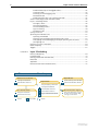
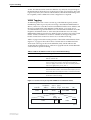
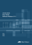
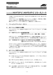
Documentation Roadmap
Uplink Module
Network Service Modules
Uplink Module Quick Install Guide
NSM Quick Install Guide
NSM Hardware Reference
Rapier Switch
Uplink Module Hardware Reference
Safety and Statutory Information
Switch Quick Install Guide
Switch Hardware Reference
Port Interface Cards
Switch Software Reference
PIC Quick Install Guide
PIC Hardware Reference
Printed
Acrobat PDF
Rapier Switch User Guide
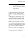
General Customer Support
Visit www.alliedtelesyn.co.nz for
the latest documentation, FAQ,
and support information
Website
Software Release 2.5.1
C613-02025-00 REV B
Introduction
5
Chapter 1
Introduction
Welcome to the Rapier Series Layer 3 Gigabit switch, combining wire speed
Layer 2 and Layer 3 IP switching, with a powerful multiprotocol routing
software suite.
Why Read This User Guide?
This User Guide describes how to get started accessing the switch’s Command
Line Interface (CLI) and its Graphical User Interface (GUI), and how to
configure the Layer 2 switching features. For more detailed descriptions of all
commands and display outputs see the Rapier Switch Software Reference. The
user guide is organised into the following chapters:
Software Release 2.5.1
C613-02025-00 REV B
■
Chapter 1, Introduction introduces the Rapier switch and gives an overview
of the features of the Rapier switch and its documentation.
■
Chapter 2, Getting Started describes how to gain access to the switch’s
command line and graphical user interfaces.
■
Chapter 3, Operating the Switch introduces general operation, management
and support features, including user authentication, loading and installing
support files, and SNMP MIBs.
■
Chapter 4, Layer 2 Switching describes how to configure Layer 2 switching
features, including switch ports, VLANs and STP.
■
Chapter 5, Layer 3 Switching describes how to use Layer 3 switching over
VLANs, including IP, Novell IPX and AppleTalk. Full descriptions of the
switch’s support for these protocols are found in the Rapier Switch Software
Reference.
6
Rapier Switch Software Reference
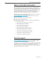
Where To Find More Information
Before installing the switch and any expansion options, read the important
safety information in the Safety and Statutory Information booklet. Follow the
Quick Install Guides step-by-step instructions for physically installing the switch
and its expansion options. The Hardware References give detailed information
about the equipment hardware. Once you are familiar with the basic
operations of the switch, use the Software Reference for full command syntax
descriptions and for full descriptions of the switch’s routing features.
The latest versions of user documentation for the Rapier family of switches can
be downloaded from the on-line support site at
http://www.alliedtelesyn.co.nz/support/rapier. The documentation set for the
Rapier switch includes:
■
Rapier Switch Safety and Statutory Information
■
Rapier Switch Quick Install Guide
■
Rapier Switch Documentation and Tools CD-ROM, which includes the
following PDF documents:
•
Rapier Switch Safety and Statutory Information
•
Rapier Switch Quick Install Guide,
•
Rapier Switch Hardware Reference
•
Rapier Switch Software Reference
•
Rapier Uplink Module Quick Install Guide
•
Rapier Uplink Module Hardware Reference
•
Network Service Module Quick Install Guide
•
Network Service Module Hardware Reference
•
Port Interface Card Quick Install Guide
•
Port Interface Card Hardware Reference
Technical support
For on-line support for your Rapier switch, see our on-line support page at
http://www.alliedtelesyn.co.nz/support/rapier. If you require further assistance,
contact your authorised Allied Telesyn distributor or reseller.
This page will also contain the latest release of the switch software. The LOAD
command can be used to download software upgrades directly from the Allied
Telesyn Research web site to the switch’s FLASH memory. Use the SET
INSTALL command to enable the new software release (“Example: Install Software Upgrade for Rapier Switch” on page 25).
Software Release 2.5.1
C613-02025-00 REV B
Introduction
7
What Can the Rapier Switch Do?
The Rapier switch software support for the Rapier Series switches and their
expansion options provides wirespeed Layer 2 switching, including support
for Virtual LANs, wirespeed Layer 3 IP switching, and Layer 3 multiprotocol
routing.
Switching Features
The main Layer 2 features of the switch are:
Software Release 2.5.1
C613-02025-00 REV B
■
High performance, non-blocking, wire-speed Layer 2 switching (“Layer 2
Switching Process” on page 46).
■
Packet Forwarding at wire speed (“The Forwarding Process” on page 48).
■
Store and Forward switching mode.
■
Autonegotiation of link speed and duplex mode for 10/100 Mbps speed on
all 100BASE TX ports (“Autonegotiation of Port Speed and Duplex Mode” on
page 32).
■
Autonegotiation of duplex mode for 10/100 and gigabit Ethernet ports
(“Autonegotiation of Port Speed and Duplex Mode” on page 32).
■
Automatic, configurable MAC address learning and ageing, supporting up
to 8191 MAC addresses per switch (“The Learning Process” on page 47).
■
Switch Filtering (“Layer 2 Filtering” on page 49).
■
Layer 3 Filtering (Switching chapter in Rapier Switch Software Reference).
■
Broadcast Storm Protection (“Packet Storm Protection” on page 34).
■
Virtual LANs defined by port membership (“Virtual Local Area Networks
(VLANs)” on page 38).
■
Spanning Tree Protocol (“Spanning Tree Protocol (STP)” on page 52).
■
Priority tagging to support four QOS egress queues (“Quality of Service” on
page 50).
■
Port trunking to spread traffic over several links (“Port Trunking” on
page 33).
■
Port mirroring (“Port Mirroring” on page 36).
■
IGMP (Internet Group Management Protocol) snooping (“IGMP Snooping”
on page 64).
8
Rapier Switch Software Reference
Routing Features
In addition to Layer 2 and Layer 3 switching, the Rapier switch provides a
wide array of multiprotocol routing, security and network management
features.
IP routing is performed at wire-speed. Other Layer 3 routing is performed by the CPU,
and increasing the routing load on the CPU decreases its performance.
Some features require the addition of WAN interfaces via Network Service
Modules (NSMs) and Port Interface Cards (PICs) installed in the NSM bay on
the rear of the switch.
Features provided by the routing software suite include:
■
IP version 4 routing
■
IP version 4 multicasting
■
IP version 6 routing
■
Network Address Translation (NAT) (not between switch ports)
■
Dynamic IP Address Assignment
■
IP Dynamic Filtering Firewall
■
IP Multihoming
■
IP RIP and IP RIPv2
■
DNS Relay
■
Demand IP
■
IP Filtering (not between switch ports)
■
IP Packet Prioritisation (not between switch ports)
■
Generic Routing Encapsulation (GRE)
■
Basic Rate and Primary Rate access to Integrated Services Digital Network
(ISDN) services, with dial-on-demand and channel aggregation.
■
Time Division Multiplexing (TDM) over G.703 links
■
Frame Relay
■
X.25
■
ARP, Proxy ARP and Inverse ARP address resolution protocols.
■
BACP (Bandwidth Allocation Control Protocol)
■
PPP Multilink
■
PPP over Ethernet (PPPoE)
■
Bandwidth on Demand
■
CLI, PAP and CHAP
■
Virtual Router Redundancy Protocol (VRRP) for fault tolerant internet
gateways (on NSM ports only)
■
IPsec
■
ISAKMP Key Management
■
Data Compression
■
Predictor Data Compression
Software Release 2.5.1
C613-02025-00 REV B
Introduction
9
■
STAC Data Compression
■
L2TP
■
Telnet client and server.
■
A sophisticated and configurable event logging facility for monitoring and
alarm notification to single or multiple management centres.
■
Triggers for automatic and timed execution of commands in response to
events.
■
Scripting for automated configuration and centralised management of
configurations.
■
Dynamic Host Configuration Protocol (DHCP) for automatically assigning
IP addresses and other configuration information to PCs and other hosts
on TCP/IP networks.
■
Group management support for IP multicasting: IGMP version 2.
■
Support for the Simple Network Management Protocol (SNMP), standard
MIBs and the Allied Telesyn Enterprise MIB, enabling the switch to be
managed by a separate SNMP management station.
■
An HTTP client that allows files to be downloaded directly from a web
server to the switch’s FLASH memory, and an HTTP server that serves web
pages from FLASH.
For a complete description of the switch’s routing software, see the Rapier
Switch Software Reference.
Special Features Licences
You need a special feature licence and password to activate some special
features over and above the standard software release. Typically, these special
features are covered by government security regulations. Special feature
licences and passwords are quite separate and distinct from the standard
software release licences and passwords. Some of the software features that
require a special features licence are:
Software Release 2.5.1
C613-02025-00 REV B
■
Triple DES S/W
■
Firewall SW
■
Firewall SMTP Application Gateway
■
Firewall HTTP Application Gateway
■
DES encryption
■
IPv6
■
BGP-4
■
IP Multicast routing: DVMRP and PIM-Sparse Mode
■
IPX routing
■
Demand IPX
■
IPX/SPX Spoofing
■
IPX Filtering (not between switch ports)
■
AppleTalk
■
Resource Reservation Protocol (RSVP)
■
Load balancer
10
Rapier Switch Software Reference
Most software features that require a special feature licence are bundled into
one of three special feature licence packs:
■
Full Layer 3 Feature Licence
■
Advanced Layer 3 Feature Licence
■
Security Pack Feature Licence
For more information contact your Allied Telesyn authorised distributor or
reseller.
For information on how to enable special feature licences see “Enabling Special
Feature Licences” on page 15.
Software Release 2.5.1
C613-02025-00 REV B
Getting Started
11
Chapter 2
Getting Started
The Rapier switch is supplied with default settings which allow it to operate
immediately as a switch, without any configuration. Even if this is all you want
to use the switch for, you should still gain access to the switch configuration, if
only to change the manager password to prevent unauthorised access.
To take advantage of the full range of advanced Layer 2 switching features, the
switch configuration must be changed. Layer 3 routing capabilities may also
require detailed configuration. The switch has both a Command Line Interface
(CLI) and a Graphical User Interface (GUI) for configuration and management.
Before you can use the GUI, you will need to login to the switch and use its CLI
to allocate an IP address.
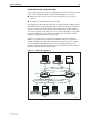
Simple Switching
If all you want the switch to do is switch traffic on your LAN, you need not
perform any configuration. Simply power up the switch and connect devices to
the switch ports. Switch learning is enabled by default, and all valid packets
will be forwarded (“Layer 2 Switching Process” on page 46).
Command Line Interface
To use the command line interface (CLI) for configuring the switch, the first
thing you need to do after physically installing the switch is to start a terminal
session to access the switch (see Table 1 and the Rapier Switch Quick Install
Guide).
To start a terminal session, do one of the following:
Software Release 2.5.1
C613-02025-00 REV B
■
Connect a VT100-compatible terminal to the RS-232 Terminal Port, set the
communications parameters on the terminal (Table 1 on page 12), and
press [Enter] a few times until the switch’s login prompt appears; or
■
Connect to the COM port of a PC running terminal emulation software
such as Windows Terminal or HyperTerminal to the RS-232 Terminal Port,
set the communications parameters on the terminal emulation software
(Table 1 on page 12), and press [Enter] a few times until the switch’s login
prompt appears.
12
Rapier Switch Software Reference
Table 1: Parameters for terminal communication .
Parameter
Value
Baud rate
9600
Data bits
8
Parity
None
Stop bits
1
Flow control
Hardware
Logging In
A user accessing the switch from a terminal or PC connected to the front panel
RS-232 terminal port (asyn0), or via a Telnet connection, must enter a login
name and password to gain access to the command prompt. When the switch
is supplied, it has a manager account with an initial password friend. Enter your
login name at the login prompt:
Enter your login name at the login prompt:
login: manager
Enter the password at the password prompt:
password: friend
This password should be changed to prevent unauthorised access to the
switch, using the command:
SET PASSWORD
Make sure you remember the new password you create, as a lost password
cannot be retrieved, and would mean losing access for configuring and
monitoring the switch.
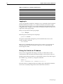
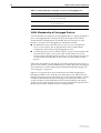
Giving the Switch an IP Address
Once you have logged into the manager account you will be able to enter
commands from this document and from the Rapier Switch Software Reference.
Enable IP, then add an IP interface over the default VLAN (vlan1) and assign it
an IP address (e.g. 192.168.1.1), using the commands:
ENABLE IP
ADD IP INTERFACE=vlan1 IPADDRESS=192.168.1.1
Once the switch is configured with an IP address, the command line interface
can also be accessed by using Telnet to the switch from an IP host.
Software Release 2.5.1
C613-02025-00 REV B
Getting Started
13
Entering Commands
The switch is controlled with commands described in this document and in the
Rapier Switch Software Reference. While the keywords in commands are not case
sensitive, the values entered for some parameters are. The switch supports
command line editing and recall (Table 2 on page 13).
Table 2: Command line editing functions and keystrokes
Function
VT100-compatible Keystroke
Move cursor within command line
←, →
Delete character to left of cursor
[Delete] or [Backspace]
Toggle between insert/overstrike
[Ctrl/O]
Clear command line
[Ctrl/U]
Recall previous command
↑ or [Ctrl/B]
Recall next command
↓ or [Ctrl/F]
Display command history
[Ctrl/C] or
SHOW ASYN HISTORY
Clear command history
RESET ASYN HISTORY
Recall matching command
[Tab] or [Ctrl/I]
The Graphical User Interface (GUI)
The switch may be configured and managed with an HTTP-based Graphical
User Interface (GUI). The GUI may be accessed with Internet Explorer version
5 or greater. A copy of Internet Explorer can be found on the switch’s
Documentation and Tools CD-ROM. JavaScript must be enabled.
Use the menus and buttons on the GUI pages to navigate, not your browser’s buttons,
to ensure that the configuration settings are saved correctly.
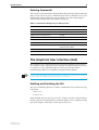
Enabling and Disabling the GUI
The GUI is enabled by default. To enable or disable the GUI, use the following
commands:
ENABLE GUI
DISABLE GUI
When enabled, the GUI will only work if a valid resource file for the hardware
model is present in FLASH memory, and if the HTTP server is enabled (see the
Operations chapter of the Rapier Switch Software Reference).
Software Release 2.5.1
C613-02025-00 REV B
14
Rapier Switch Software Reference
Accessing the GUI
To allow the GUI to be browsed to, the switch’s VLAN1 interface must be given
an IP address. In some situations, routing information must also be configured.
For more information about IP configuration, see the Internet Protocol (IP)
chapter of the Rapier Switch Software Reference).
You can optionally browse to the GUI with a Secure Sockets Layer (SSL)
connection. This means that sensitive data including passwords and email
addresses can not be accessed by malicious parties. For details on configuring a
SSL connection for the GUI, refer to the Secure Sockets Layer (SSL) chapter of the
Rapier Switch Software Reference).
To access the GUI:
1.
Access the switch’s command line interface.
See the switch’s Quick Install Guide for more information.
2.
Enable IP, using the command:
ENABLE IP
3. Assign the VLAN1 interface an IP address in the required subnet, using the
command:
SET IP INTERFACE=vlan1 IP=ipaddress MASK=mask
4. If the PC from which you will access the GUI is on a different subnet to the
switch, add a route from the PC to the switch, using the command:
ADD IP ROUTE=PC-ipaddress INTERFACE=vlan1
NEXTHOP=switch-ipaddress
5. If you access the Internet through a proxy server, set your browser to bypass
the proxy for the VLAN1 interface’s IP address.
6.
Point your web browser at VLAN1’s IP address.
7.
At the login prompt, enter the user name and password.
User Name: manager
Password: friend
The home page is displayed. Select options to configure and manage the
switch.
To change the password, select Management > Users from the sidebar menu.
Select the Manager account and click Modify.
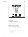
Getting help
To access the GUI’s context-sensitive help system, click on the Help button in
the sidebar menu.
Software Release 2.5.1
C613-02025-00 REV B
Getting Started
15
Enabling Special Feature Licences
You must enable the special feature licence you have purchased before you can
use the licenced features. You will need the password provided by your
authorised distributor or reseller. The advanced upgrade licence and password
are different from the standard software release licence and password. The
licence cannot be transferred from one router to another.
For software features that require a special feature licence see “Special Features
Licences” on page 9.
You must order passwords for special feature licences from your authorised distributor
or reseller. You must specify the special feature licence bundle and the serial number(s)
of the switch(s) on which the special feature licences are to be enabled.
The password for a special feature licence is a string of at least 16 hexadecimal
characters, and encodes the special feature or features covered by the license,
and the switch serial number. The password information is stored in the
switch’s FLASH memory.
To enable or disable the AT-RPFL3Upgrade use the commands:
ENABLE FEATURE=AT-RPFL3Upgrade PASSWORD=password
DISABLE FEATURE=AT-RPFL3Upgrade
Other features on the switch, such as Firewall, Remote Secure Shell and Triple
DES encryption, and support for Public Key Infrastructure may also need
special feature licences. To list the current special feature licences use the
command:
SHOW FEATURE[={featurename|index}]
Software Release 2.5.1
C613-02025-00 REV B
Operating the Switch
17
Chapter 3
Operating the Switch
This chapter introduces general operation, management and support features,
including user authentication, loading and installing support files, and SNMP
MIBs. For more information see Chapter 1, Operation in the Rapier Switch
Software Reference.
User Privileges
The command processor supports three levels of privilege, USER, MANAGER,
and SECURITY OFFICER, distinguished by the prompt displayed by the
command processor when it is ready to receive commands. A USER level
prompt looks like:
>
while a MANAGER prompt looks like:
Manager >
and a SECURITY OFFICER prompt looks like:
SecOff >
See Chapter 1, Operation in the Rapier Switch Software Reference for more
information about creating new accounts with user, manager and security
officer privileges.
File Subsystem
FLASH memory is structured like a file subsystem. Files can be saved,
renamed, listed and deleted. Release files, online help files, configuration
scripts and other scripts are all stored as files in FLASH memory.
File names of up to 16 characters long, with extensions of 3 characters (DOS
16.3 format), are supported on the switch. However, files on the switch are
stored in FLASH and NVS using the DOS 8.3 format of 8 characters long, with
extensions of 3 characters. For example, the file extralongfilenam.cfg may
be saved as extral~1.cfg in the FLASH File System. Therefore, files can be
accessed via two file names, either of which can be used for file management.
A translation table, named longname.lfn, converts file names between DOS
16.3 format and DOS 8.3 format. To reconcile file names the switch consults the
Software Release 2.5.1
C613-02025-00 REV B
18
Rapier Switch Software Reference
translation table which is synchronised with file contents in memory. For more
information about working with files see the Working With Files section,
Operation chapter, AR400 Series Router Software Reference.
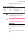
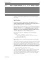
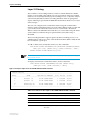
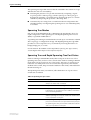
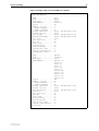
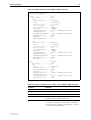
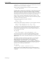
To display the files in FLASH, use the command:
SHOW FILE
Table 3: Example output from the SHOW FILE command.
Filename
Device
Size
Created
Locks
---------------------------------------------------------------------------28-72.pat
flash
111764
05-May-1997 12:41:42
0
28-74ang.rel
flash
2013756 09-May-1997 15:58:55
0
28f72-06.pat
flash
123268
18-Apr-1997 15:58:16
0
release.lic
flash
32
08-May-1997 16:43:49
0
test.cfg
flash
1698
09-May-1997 10:39:42
0
config.ins
nvs
32
09-May-1997 10:22:46
0
sixteenalongfile.scp
flash
24
30-May-1997 15:10:12
0
----------------------------------------------------------------------------
The Locks field indicates the number of concurrent processes using the file.
The switch automatically compacts FLASH memory when a maximum
threshold of deleted files is reached. Compaction frees space for new files by
discarding garbage. A message will appear when FLASH compaction has been
activated. Another message appears when FLASH compaction is complete.
While FLASH is compacting, do not restart the switch or use any commands
that affect the FLASH file subsystem. Do not restart the switch, or create, edit,
load, rename or delete any files until a message confirms that FLASH file
compaction is completed. Interrupting flash compaction may result in damage
to files.
Online CLI Help
Online help is available for all switch commands in the CLI. Typing a question
mark “?” at the end of a partially completed command displays a list of the
parameters that may follow the current command line, with the minimum
abbreviations in uppercase letters. The current command line is then redisplayed, ready for further input.
An online help facility provides more detailed help information via the
command:
HELP [topic]
If a topic is not specified, a list of available topics is displayed. The HELP
command displays information from the system help file stored in FLASH
memory. The help file used by the HELP command must be defined using the
command:
SET HELP=helpfile
Software Release 2.5.1
C613-02025-00 REV B
Operating the Switch
19
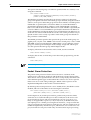
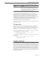
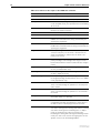
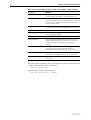
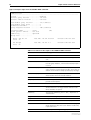
The current help file and other system information can be displayed with the
command:
SHOW SYSTEM
Table 4: Example of output from the SHOW SYSTEM command
Switch System Status
Time 14:29:17 Date 12-Sep-2000.
Board
ID Bay Board Name
Rev
Serial number
-------------------------------------------------------------------------Base
86
AT-RP24 Rapier 24
P2-1 49867449
-------------------------------------------------------------------------Memory DRAM : 32768 kB
FLASH : 6144 kB
-------------------------------------------------------------------------SysDescription
CentreCOM AT-RP24 Rapier 24 version 2.1.0-00 04-Sep-2000
SysContact
SysLocation
SysName
SysUpTime
30262 ( 00:05:02 )
Software Version: 2.1.0-00 04-Sep-2000
Release Version : 2.1.0-00 04-Sep-2000
Release built
: Sep 12 2000 at 14:28:59
Patch Installed : NONE
Territory
: usa
Help File
: help.hlp
Main PSU
RPS Monitor
RPS PSU
: On
: On
: On
Main Fan
RPS Connected
: On
: Yes
Boot configuration file: vts.cfg (exists)
Current configuration: vts.cfg
Security Mode
: Disabled
Warning (248283): No patches found.
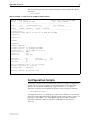
Configuration Scripts
At boot the switch executes the commands in the boot script to configure the
switch. A boot script is a sequence of standard commands that the switch
executes at start-up. The default boot script is called boot.cfg, but an
alternative script file can be defined as the boot script using the command:
SET CONFIG=filename
A configuration file is a script made up of the same commands as are used in
the CLI. It can be edited manually using the switch’s built in editor (“Editor” on
page 20), or uploaded to a PC and edited using any text editor using the
UPLOAD command (Chapter 1, Operation in the Rapier Switch Software
Reference).
Software Release 2.5.1
C613-02025-00 REV B
20
Rapier Switch Software Reference
Saving Configuration Entered with the GUI
Configuration changes applied using the GUI can be saved to a configuration
script by clicking the Save button on any GUI page that has one. A pop-up Save
window gives the option of saving to the boot configuration file, the current
configuration file, another existing file or a new file.
Saving Configuration Entered with the CLI
Subsequent commands entered from the command line or executed from a
script affect only the dynamic configuration in memory, which is not retained
over a power cycle. Changes are not automatically stored in nonvolatile
memory. When the switch is restarted the configuration will be restored to that
defined by the boot script, or if the switch was restarted using the RESTART
command, any script specified in the RESTART command.
To retain any configuration changes made after boot across a restart or power
cycle, save the modified configuration as a script file, using the command:
CREATE CONFIG=filename
The configuration file created by the GUI or the CREATE CONFIG command records
passwords in encrypted form, not in cleartext.
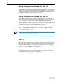
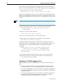
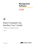
Editor
The switch has a built-in full-screen text editor for editing script files stored on
the switch file subsystem. Scripts can be run manually, or run when a trigger
automatically activates on some specified events in the switch. See “Triggers”
on page 67, and the Trigger Facility chapter in the Rapier Switch Software
Reference. To access the editor, use the command:
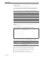
EDIT [filename]
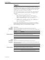
The file name is optional as a file can be loaded, or a new file can be created
from within the editor itself (Figure 1 on page 21).
Software Release 2.5.1
C613-02025-00 REV B
Operating the Switch
21
Figure 1: The editor screen layout.
The editor uses VT100 command sequences and should only be used with a
VT100-compatible terminal, terminal emulation program or Telnet client.
To display editor Help at any time while in the editor press [Ctrl/K,H]; that is,
hold down the Ctrl key and press in turn the K key then the H key.
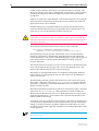
Install Information
The INSTALL module is responsible for maintaining install information and
loading the correct install at boot. A release is a binary file containing the code
executed by the switches CPU. There may also be a patch file, and additional
binary file that modifies the original release file. An install is a record
identifying a release and an optional patch. Three installs are maintained by
the INSTALL module, temporary, preferred and default.
The default install is the install of last resort. The release for the default install
can not be changed by the manager and is always the EPROM release. The
patch for the default install may be set by the manager.
The temporary and preferred installs are completely configurable. Both the
release and an associated patch may be set. The release may be EPROM or a
release stored in FLASH.
The three different installs are required to handle the following situations:
■
A default install is required to handle the case when only the EPROM
release is present.
■
A temporary install is required to allow a release and/or patch to be
loaded once only, in case it causes a switch crash.
■
A preferred install is required because the default install can not be
anything other than the EPROM.
The install information is inspected in a strict order. The temporary install is
inspected first. If this install information is present, the temporary install is
Software Release 2.5.1
C613-02025-00 REV B
22
Rapier Switch Software Reference
loaded. At the same time, the temporary install information is deleted. This
ensures that if the switch reboots immediately as the result of a fatal condition
caused by the temporary install, the temporary install will not be loaded a
second time.
If there is no temporary install defined, or the install information is invalid, the
preferred install is inspected. If present, this install is loaded. The preferred
install information is never deleted.
If neither temporary nor preferred installs are present, the default install is
used. The default install will always be present in the switch, because if, for
some reason, it is not, the INSTALL module will restore it.
The preferred install should not be set up with an untested release or patch. It
is advisable to install new releases or patches as the temporary install, and
when the switch boots correctly, to then set up the preferred install with the
new release or patch.
To change the install information in the switch, use the command:
SET INSTALL={TEMPORARY|PREFERRED|DEFAULT}
[RELEASE={release-name|EPROM}] [PATCH[=patch-name]]
The INSTALL parameter specifies which install is to be set. The INSTALL
module is responsible for maintaining install information and loading the
correct install at boot. An install is a record identifying a release and an optional
patch. Three installs are maintained by the INSTALL module, temporary,
preferred and default.
The default install is the install of last resort. The release for the default install
can not be changed by the manager and is always the EPROM release. The
patch for the default install may be set by the manager.
The temporary and preferred installs are completely configurable. Both the
release and an associated patch may be set. The release may be EPROM or a
release stored in FFS.
The RELEASE parameter specifies the release file for this install. The release
file is either a file name of the form device:filename.ext for files in the file
subsystem, or EPROM, to indicate the EPROM release. The default value for
the device field is FLASH.
The PATCH parameter specifies the patch file for this install, and is a file name
of the form device:filename.ext. The patch file is stored in FLASH. The
default value for the device field is FLASH. If the patch name is not given, the
patch file information for a given install is removed and only the release file
will be loaded for the install.
A patch file can not be set up for an install unless a release file is already set up,
or a release file is specified in the same command. This stops the inadvertent
setting of an install to be just a patch file. When the switch reboots in such a
case the particular install is ignored, which may have undesirable effects on the
switch operation.
For security reasons this command will only be accepted if the user has SECURITY
OFFICER privilege.
Software Release 2.5.1
C613-02025-00 REV B
Operating the Switch
23
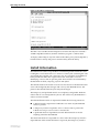
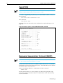
To delete a particular install (except the default install) use the command:
DELETE INSTALL
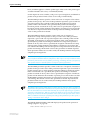
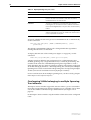
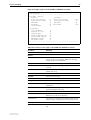
To display the current install information, including which install is currently
running in the switch, and how the install information was checked at the last
reboot, use the command:
SHOW INSTALL
Table 5: Example output from the SHOW INSTALL command.
Install
Release
Patch
Dmp
------------------------------------------------------------------------Temporary
Preferred
flash:86s-210.rez
Default
EPROM (8-1.6.0)
------------------------------------------------------------------------Current install
------------------------------------------------------------------------Preferred
flash:8d-181.rez
------------------------------------------------------------------------Install history
------------------------------------------------------------------------No Temporary install selected
Preferred install selected
Preferred release successfully installed
Preferred patch successfully installed
-------------------------------------------------------------------------
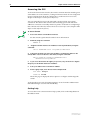
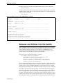
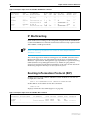
Releases and Patches into the Switch
The LOADER module is responsible for loading and storing releases, patches
and other files into FLASH. The LOADER module uses the Trivial File Transfer
Protocol (TFTP), Hypertext Transfer Protocol (HTTP) or ZMODEM over an
asynchronous port, to retrieve files from a network host. The FFS module is
used to create, write and destroy release and patch files.
The loader can be configured with the command:
SET LOADER [DELAY=delay|DEFAULT]
[DESTINATION={FLASH|DEFAULT}] [FILE=filename]
[HTTPPROXY={hostname|ipadd|DEFAULT}]
[METHOD={HTTP|TFTP|WEB|WWW|ZMODEM|NONE|DEFAULT}]
[ASYN=port|DEFAULT] [PROXYPORT=1..65535|DEFAULT]
[SERVER={hostname|ipadd|DEFAULT}]
This command sets default values for the name of the file to load, the network
host to load it from, and the memory location in which to store the file. These
default values can be overridden when the load actually takes place. A time
delay between initiating a load and the start of the load can also be configured.
The DELAY parameter specifies the delay, in seconds, between initiating the
file download and the download actually starting. This feature is provided to
allow reconfiguration of ports and devices after initiating the download. For
example, a manager may be at a remote site with a single PC which is to act as
both the access device to the switch and the TFTP server. By specifying a delay,
the manager has time to reconfigure the PC from terminal emulation mode to
Software Release 2.5.1
C613-02025-00 REV B
24
Rapier Switch Software Reference
TFTP server mode before the download starts. The DELAY parameter is
optional. If DEFAULT is specified, this parameter is set to the factory default,
which is no delay.
The DESTINATION parameter specifies where the file will be stored. If FLASH
is specified, the file is stored in the FLASH File System (FFS) on the switch. If
DEFAULT is specified, this parameter is set to the factory default, FLASH.
The FILE parameter specifies the name of the file, in the syntax of the server
from which the file will be downloaded. The FILE parameter is a full path
name rather than just a file name. The only restriction is that the last part of the
parameter must be a valid file name for the LOADER module. When
METHOD is set to TFTP, HTTP, ZMODEM or NONE, valid file names are of
the form filename.ext where filename is one to sixteen characters in length
and ext is three characters in length. The following are examples of valid file
names for methods TFTP, ZMODEM or NONE:
\user\public\filename.ext ; UNIX or DOS server
[network.cfg]filename.ext ; DEC VAX server
Note that, starting at the end of the file name and working backwards, the first
character not valid in file names delimits a valid file name for the switch. If the
slash at the beginning of the path is omitted in this command, the LOAD
command adds it. The following are examples of valid file names for method
HTTP:
/path/filename.ext
path/filename.ext
The HTTPPROXY parameter specifies the proxy server used to handle HTTP
requests. Either the IP address or the fully qualified domain name of the proxy
server may be specified. If a domain name is specified, the switch will perform
a DNS lookup to resolve the name. If DEFAULT is specified, this parameter is
set to the factory default, which has no value set for HTTPPROXY, clearing any
value previously set as default.
The METHOD parameter specifies the method to use when downloading the
file. If HTTP is specified, HTTP is used to download the file. The options WEB
and WWW are synonyms for HTTP. If TFTP is specified, TFTP is used to
download the file. If ZMODEM is specified, the ZMODEM protocol is used to
download the file. If ZMODEM is specified, the PORT parameter must be
specified, unless it has been set with the SET LOADER command. If NONE is
specified, only text files can be downloaded and all input received via the port
will be directed to the specified file on the switch’s file subsystem. The file
transfer is terminated by the first control character received that is not a CR or
LF character. The FILE parameter is not valid when METHOD is set to
ZMODEM. The PORT parameter is not valid when METHOD is set to HTTP,
WEB, WWW, TFTP or NONE. If DEFAULT is specified, this parameter is set to
the factory default, which is TFTP.
The ASYN parameter specifies the asynchronous port via which the file will be
downloaded, when the METHOD parameter is set to ZMODEM or NONE. If
METHOD is set to ZMODEM or NONE, the PORT parameter is required
unless it has been set with the SET LOADER command. If DEFAULT is
specified, this parameter is set to the factory default, which is no PORT set,
clearing any value previously set as default.
The PROXYPORT parameter specifies the port on a proxy server. The
PROXYPORT parameter is only valid if METHOD is HTTP and HTTPPROXY
is specified. If DEFAULT is specified, this parameter is set to the factory
default, which is 80.
Software Release 2.5.1
C613-02025-00 REV B
Operating the Switch
25
The SERVER parameter specifies the IP address or the host name (a fully
qualified domain name) of the TFTP server or HTTP server from which the file
is loaded. If a host name is specified, a DNS lookup is used to translate this to
an IP address. The SET IP NAMESERVER command can be used to define
name servers. The PING command can be used to verify that the switch can
communicate with the server via IP. The SERVER parameter is not used when
METHOD is set to ZMODEM or NONE. The following are examples of valid
server names when METHOD is set to HTTP:
host.company.com
192.168.3.4
If DEFAULT is specified, this parameter is set to the factory default, which has
no value set for SERVER, clearing any value previously set as default.
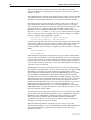
Example: Install Software Upgrade for Rapier Switch
This example downloads a compressed release from the Rapier Support site to
the switch’s FLASH memory using HTTP.
To install a compressed release:
1.
Download the release files to the switch.
The release file is downloaded to the switch with the command:
LOAD METHOD=HTTP DESTINATION=FLASH
FILE=/support/rapier/downloads/86s-210.rez
SERVER=www.alliedtelesyn.co.nz HTTPPROXY=proxy-address
PROXYPORT=proxy-port
where proxy-address is the fully qualified domain name (e.g.
proxy.mycompany.com) or IP address (e.g. 192.168.1.1) of the proxy server,
and proxy-port is the port number of the proxy port on the proxy server. If
access from the switch to the world wide web is not via a proxy server, the
HTTPPROXY and PROXYPORT parameters should be omitted.
The process of downloading a release file can take some time, even if the
switch and the HTTP server are connected by high speed links. An
indicative time for downloading a release over Ethernet is 5 to 10 minutes.
The progress of the download can be monitored with the command:
SHOW LOAD
When the download has completed, the presence of the files in FLASH can
be displayed with the command:
SHOW FILE
This shows the file 86s-210.rez is present.
2.
Test the release.
The release can now be tested, using the command:
SET INSTALL=TEMPORARY RELEASE=86s-210.REZ
The install information can be checked with the command:
SHOW INSTALL
The switch is then rebooted, and the install is checked again. This display
should indicate, in the install history, that the temporary install was
loaded.
Software Release 2.5.1
C613-02025-00 REV B
26
Rapier Switch Software Reference
3.
Make the release the default (permanent) release.
If the switch operates correctly with the new release, the release may be
made permanent with the command:
SET INSTALL=PREFERRED RELEASE=86s-210.REZ
Every time the switch reboots from now on, the new release will be loaded
from FLASH.
Other load methods are described in the Operations chapter in the Rapier Switch
Software Reference.
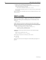
SNMP and MIBs
The switch’s implementation of SNMP is based on RFC 1157 “A Simple Network
Management Protocol (SNMP)”, and RFC 1812, “Requirements for IP Version 4
Routers”. The SNMP agent is disabled by default. To enable SNMP, use the
command:
ENABLE SNMP
SNMP communities are the main configuration item in the switch’s SNMP
agent, and are defined in terms of a list of IP addresses which define the SNMP
application entities (trap hosts and management stations) in the community.
An SNMP community is created using the command:
CREATE SNMP COMMUNITY=name [ACCESS={READ|WRITE}]
[TRAPHOST=ipadd] [MANAGER=ipadd]
[OPEN={ON|OFF|YES|NO|TRUE|FALSE}]
Authentication failure traps and link state traps can be enabled using the
commands:
ENABLE SNMP AUTHENTICATE_TRAP
ENABLE INTERFACE=interface LINKTRAP
where interface is the name of an interface, such as vlan11.
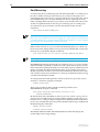
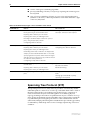
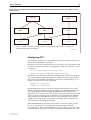
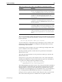
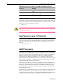
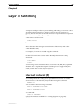
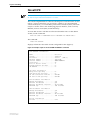
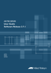
The command:
SHOW SNMP
displays the current state and configuration of the SNMP agent (Figure 2 on
page 27).
Software Release 2.5.1
C613-02025-00 REV B
Operating the Switch
27
Figure 2: Example output from the SHOW SNMP command.
SNMP configuration:
Status ..........................
Authentication failure traps ....
Community .......................
Access ........................
Status ........................
Traps .........................
Open access ...................
Community .......................
Access ........................
Status ........................
Traps .........................
Open access ...................
Enabled
Enabled
public
read-only
Enabled
Enabled
Yes
Administration
read-write
Disabled
Disabled
No
SNMP counters:
inPkts ..........................
inBadVersions ...................
inBadCommunityNames .............
inBadCommunityUses ..............
inASNParseErrs ..................
inTooBigs .......................
inNoSuchNames ...................
inBadValues .....................
inReadOnlys .....................
inGenErrs .......................
inTotalReqVars ..................
inTotalSetVars ..................
inGetRequests ...................
inGetNexts ......................
inSetRequests ...................
inGetResponses ..................
inTraps .........................
0
0
0
0
0
0
0
0
0
0
0
0
0
0
0
0
0
outPkts .........................
outTooBigs ......................
outNoSuchNames ..................
outBadValues ....................
outGenErrs ......................
outGetRequests ..................
outGetNexts .....................
outSetRequests ..................
outGetResponses .................
outTraps ........................
The following MIBs are supported:
Software Release 2.5.1
C613-02025-00 REV B
■
MIB II (RFC 1213)
■
Ethernet MIB (RFC 1643)
■
Trap MIB (RFC 1215)
■
RMON Groups 1, 2, 3, and 9 (RFC 1757)
■
AR Router portion of the ATI/ATKK Enterprise MIB
■
Portions of the Extended Interface MIB (RFC 1573)
0
0
0
0
0
0
0
0
0
0
Layer 2 Switching
29
Chapter 4
Layer 2 Switching
This section describes the Layer 2 switching features on the Rapier switch, and
how to configure them.
Switch Ports
Each Ethernet switch port is uniquely identified by a port number. The switch
supports a number of features at the physical level that allow it to be connected
in a variety of physical networks. This physical layer (layer 1) versatility
includes:
■
Enabling and disabling of Ethernet ports.
■
Auto negotiation of port speed and duplex mode for all 10/100 Ethernet
ports.
■
Manual setting of port speed and duplex mode for all 10/100 Ethernet
ports.
■
Link up and link down triggers.
■
Port trunking.
■
Packet storm protection.
■
Port mirroring.
■
Support for SNMP management
Enabling and Disabling Switch Ports
An switch port that is enabled is available for packet reception and
transmission. Its administrative status in the Interfaces MIB is UP. Conversely,
an Ethernet port that is disabled is not available for packet reception and
transmission. It will not send or receive any frames; incoming STP BPDU
packets are discarded. Its administrative status in the Interfaces MIB is DOWN.
Every Ethernet port on the switch is enabled by default. Disabling a switch
port does not affect the STP operation on the port. Enabling a switch port will
allow the port to participate in spanning tree negotiation. A switch port that
has been disabled by the Port Security feature cannot be enabled using the
ENABLE SWITCH PORT command.
To enable or disable a switch port, use the commands:
ENABLE SWITCH PORT={port-list|ALL}
DISABLE SWITCH PORT={port-list|ALL}
Software Release 2.5.1
C613-02025-00 REV B
30
Rapier Switch Software Reference
Resetting Ethernet ports at the hardware level discards all frames queued for
reception or transmission on the port, and restarts autonegotiation of port
speed and duplex mode. Ports are reset using the command:
RESET SWITCH PORT={port-list|ALL} [COUNTER]
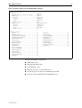
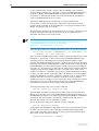
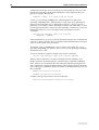
To display information about switch ports, use the command:
SHOW SWITCH PORT[={port-list|ALL}]
Figure 3: Example output from the SHOW SWITCH PORT command.
Switch Port Information
--------------------------------------------------------------------------Port .......................... 1
Description ................... To intranet hub, port 4
Status ........................ ENABLED
Link State .................... Up
UpTime ........................ 00:10:49
Port Media Type ............... ISO8802-3 CSMACD
Configured speed/duplex ....... Autonegotiate
Actual speed/duplex ........... 1000 Mbps, full duplex
Configured master/slave mode .. Autonegotiate
Actual master/slave mode ...... Master
Acceptable Frame Types ........ Admit All Frames
Broadcast rate limit .......... 1000/s
Multicast rate limit .......... DLF rate limit ................ Learn limit ................... Intrusion action .............. Trap
Current learned, lock state ... 15, not locked
Mirroring ..................... Tx, to port 22
Is this port mirror port ...... No
Enabled flow control(s) ....... Jamming
Pause
Send tagged pkts for VLAN(s) .. marketing (87)
sales (321)
Port-based VLAN ............... accounting (42)
Ingress Filtering ............. OFF
Trunk Group ................... STP ........................... company
Multicast filtering mode ...... (B) Forward all unregister groups
--------------------------------------------------------------------------Table 6: Parameters in the output of the SHOW SWITCH PORT command
Parameter
Meaning
Port
The number of the switch port.
Description
A description of the port.
Status
The state of the port; one of “ENABLED” or “DISABLED”.
Link state
The link state of the port, one of “Up” or “Down”.
Uptime
The count in hours:minutes:seconds of the elapsed time
since the port was last reset or initialised.
Port Media Type
The MAC entity type as defined in the MIB object ifType.
Configured speed/duplex
The port speed and duplex mode configured for this port.
One of “Autonegotiate” or a combination of a speed (one
of “10 Mbps”, “100 Mbps” or “1000 Mbps”) and a duplex
mode (one of “half duplex” or “full duplex”).
Software Release 2.5.1
C613-02025-00 REV B
Layer 2 Switching
31
Table 6: Parameters in the output of the SHOW SWITCH PORT command
Parameter
Meaning
Actual speed/duplex
The port speed and duplex mode that this port is actually
running at. A combination of a speed (one of “10 Mbps”,
“100 Mbps” or “1000 Mbps”) and a duplex mode (one of
“half duplex” or “full duplex”).
Configured master/slave mode The master/slave mode configured for this port; one of
“Autonegotiate’, “Master”, “Slave” or “Not applicable”.
Actual master/slave mode
The master/slave mode actually selected; one of “-”,
“Master”, “Slave” or “Not applicable”.
Acceptable Frames Types
The value of the Acceptable Frames Type parameter, one of:
“Admit All Frames” or “Admit Only VLAN-tagged Frames”.
Broadcast rate limit
The limit of the rate of reception of broadcast frames for
this port, in frames per second.
Multicast cast rate limit
The limit of the rate of reception of multicast frames for this
port, in frames per second.
DLF rate limit
The limit of the rate of reception of DLF (destination lookup
failure) frames for this port, in frames per second.
Learn limit
The number of MAC addresses that may be learned for this
port. Once the limit is reached, the port is locked against
any new MAC addresses. One of “None” or a number from
1 to 256.
Intrusion action
The action taken on this port when a frame is received from
an unknown MAC address when the port is locked. One of
“None”, “Discard”, “Trap” or “Disable”.
Current learned, lock state
The number of MAC addresses currently learned on this
port and the state of locking for this port. The lock state is
one of “not locked”, “locked by limit” or “locked by
command”.
Mirroring
The traffic mirroring for traffic in and out of this port. One
of “None”, “Rx” (for traffic received by this port), “Tx” (for
traffic sent on this port) or “Both”. The port to which
mirrored frames are being sent is also displayed.
Is this port mirror port
Whether or not this port is a mirror port. One of “No” or
“Yes”.
Enabled flow control(s)
Flow control parameters set for the port; zero, one or two
of ”Jamming” and “Pause”. If flow control is implemented
on the switch, then this kind of flow control is applied to the
port.
Send tagged pkts for VLAN(s) The name and VLAN Identifier (VID) of the tagged VLAN(s),
if any, to which the port belongs.
Port-based VLAN
The name and VLAN Identifier (VID) of the port-based VLAN
to which the port belongs.
Ingress Filtering
The state of Ingress Filtering: one of “ON” or “OFF”.
Trunk Group
Name of trunk group to which the port belongs, if any.
STP
The name of the STP to which the port belongs.
Software Release 2.5.1
C613-02025-00 REV B
32
Rapier Switch Software Reference
Autonegotiation of Port Speed and Duplex Mode
Each of the switch ports can operate at either 10 Mbps or 100 Mbps, in either
full duplex or half duplex mode. In full duplex mode a port can transmit and
receive data simultaneously, while in half duplex mode the port can either
transmit or receive, but not at the same time. This versatility makes it possible
to connect devices with different speeds and duplex modes to different ports
on the switch. Such versatility also requires that each port on the switch know
which speed and mode to use.
Autonegotiation allows the ports to adjust their speed and duplex mode to
accommodate the devices connected to them. Each switch port can be either
configured with a fixed speed and duplex mode, or configured to
autonegotiate speed and duplex mode with a device connected to it to
determine a speed and mode that will allow successful transmission. An
autonegotiating port will adopt the speed and duplex mode required by
devices connected to it. If another autonegotiating device is connected to the
switch, they will negotiate the highest possible common speed and duplex
mode (Table 7). Setting the port to a fixed speed and duplex mode allows it to
support equipment that cannot autonegotiate.
It is also possible to require a port to operate at a single speed without
disabling autonegotiation by allowing the port to autonegotiate but constrain
the speed/duplex options to the desired combination. For example, if one end
of a link is set to AUTO and other to 100MFULL then the AUTO end will select
100MHALF operation because without the other end autonegotiating the
AUTO end has no way of knowing that the fixed end is full duplex capable. If a
particular speed is required it is usually preferable to fix the speed/duplex
combination using one of the autonegotiating speed values. Therefore, using
100MFAUTO at one end of a link and will allow the AUTO end to
autonegotiate 100MFULL.
Switch ports will autonegotiate by default when they are connected to a new
device. To change this setting, use the command:
SET SWITCH PORT={port-list|ALL}
SPEED={AUTONEGOTIATE|10MHALF|10MFULL|10MHAUTO|10MFAUTO|10
0MHALF|100MFULL|100MHAUTO|100MFAUTO|1000MHALF|1000MFULL|1
000MHAUTO|1000MFAUTO}
Autonegotiation can also be activated at any time after this, on any port that is
set to autonegotiate, by using the command:
ACTIVATE SWITCH PORT={port-list|ALL} AUTONEGOTIATE
On the first switch, the gigabit uplink ports always use 1000 Mbps speed and
operate in full duplex mode, but these ports can also autonegotiate with peers
in order to successfully pass the negotiation phase to get to successful
operation.
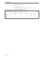
Table 7: Autonegotiation preferences for Ethernet ports.
Speed
Rapier 24/48 Rapier 24/48 Rapier 24/48
10/100
Cu uplink
fibre uplink Rapier G6f
Rapier G6
Rapier G6
Rapier G6x
fibre uplink Cu uplink
10MHALF
Yes
No
No
No
Yes
No
Yes
10MFULL
Yes
No
No
No
Yes
No
Yes
100MHALF
Yes
No
No
No
Yes
No
Yes
100MFULL
Yes
No
No
No
Yes
No
Yes
1000MHALF
No
Yes
Yes
Yes
Yes
No
Yes
Software Release 2.5.1
C613-02025-00 REV B
Layer 2 Switching
Speed
33
Rapier 24/48 Rapier 24/48 Rapier 24/48
10/100
Cu uplink
fibre uplink Rapier G6f
Rapier G6
Rapier G6
Rapier G6x
fibre uplink Cu uplink
1000MFULL
No
Yes
Yes
Yes
Yes
Yes
Yes
10MHAUTO
Yes
No
No
No
Yes
No
Yes
10MFAUTO
Yes
No
No
No
Yes
No
Yes
100MHAUTO
Yes
No
No
No
Yes
Yes
Yes
100MFAUTO
Yes
No
No
No
Yes
No
Yes
1000MHAUTO
No
Yes
Yes
Yes
Yes
Yes
Yes
1000MFAUTO
No
Yes
Yes
Yes
Yes
Yes
Yes
The SHOW SWITCH PORT command displays the port speed and duplex
mode settings.
Port Trunking
Port trunking, also known as port bundling or link aggregation, allows a
number of ports to be configured to join together to make a single logical
connection of higher bandwidth. This can be used where a higher performance
link is required, and makes links even more reliable.
The switch supports up to 6 trunk groups, of up to 8 switch ports each. The two
gigabit Ethernet ports can also be grouped together to form a trunk group. It is
not possible for a trunk group to include both 10/100 Ethernet and gigabit
Ethernet ports. Ports in the trunk group do not have to be contiguous. Port
trunking is supported between AR800 Series and Rapier switches, and may be
compatible with trunking algorithms on third party devices.
Port trunk groups are created and destroyed on the switch using the
commands:
CREATE SWITCH TRUNK=trunk [PORT=port-list]
[SELECT={MACSRC|MACDEST|MACBOTH|IPSRC|IPDEST|IPBOTH}]
[SPEED={10M|100M|1000M}]
DESTROY SWITCH TRUNK=trunk
Port trunk groups can only be destroyed on the switch if no ports belong to
them.
All the ports in a trunk group must belong to the same VLAN. Ports in a trunk
group can be added to other VLANs, either as individual ports or as an entire
group. A port in a trunk group cannot be deleted from any of the VLAN(s) to
which the whole trunk group belongs, unless it is first removed from the trunk
group. The members of a trunk group can be specified when it is created, and
ports can be added to or removed from a trunk group using the commands:
ADD SWITCH TRUNK=trunk PORT=port-list
DELETE SWITCH TRUNK=trunk PORT={port-list|ALL}
Ports which are members of a trunk group must operate in full duplex mode.
When a port is added to a trunk group, the speed setting for the group
overrides the speed setting previously configured for the port. When a port is
removed from a trunk group, the port returns to its previously configured
speed and duplex mode settings.
Software Release 2.5.1
C613-02025-00 REV B
34
Rapier Switch Software Reference
The speed of the trunk group can either be specified when it is created, or set
using the command:
SET SWITCH TRUNK=trunk
[SELECT={MACSRC|MACDEST|MACBOTH|IPSRC|IPDEST|IPBOTH}]
[SPEED={10M|100M|1000M}]
The SELECT parameter specifies the port selection criterion for the trunk
group. Each packet to be sent on the trunk group is checked, using the selection
criterion, and a port in the trunk group chosen down which to send the packet.
If MACSRC is specified, the source MAC address is used. If MACDEST is
specified, the destination MAC address is used. If MACBOTH is specified,
both source and destination MAC addresses are used. If IPSRC is specified, the
source IP address is used. If IPDEST is specified, the destination IP address is
used. If IPBOTH is specified, both the source and destination IP addresses are
used. The user of the switch should choose the value of this parameter to try to
spread out the load as evenly as possible on the trunk group. The default for
this parameter is MACDEST.
The SPEED parameter specifies the speed of the ports in the trunk group. For
gigabit ports, only the value 1000M is allowed. For switch ports, values of 10M
and 100M are allowed. The default is 100M. When a port is added to a trunk
group, its current speed and duplex mode settings are ignored and the port
uses the speed of the trunk group and full duplex mode.
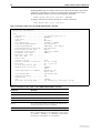
To display information about trunks on the switch, use the command:
SHOW SWITCH TRUNK[=trunk]
To display the VLANs to which the ports in the trunk groups belong, use the
command:
SHOW VLAN[=ALL]
Port trunking must be configured on both ends of the link, or network loops may result.
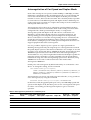
Packet Storm Protection
The packet storm protection feature allows the user to set limits on the
reception rate of broadcast, multicast and destination lookup failure packets.
The software allows separate limits to be set for each port, beyond which each
of the different packet types are discarded. The software also allows separate
limits to be set for each of the packet types. Which of these options can be
implemented depends on the model of switch hardware.
By default, packet storm protection is set to NONE, that is, disabled. It can be
enabled, and each of the limits can be set using the command:
SET SWITCH PORT=port-list [BCLIMIT={NONE|limit}]
[DLFLIMIT={NONE|limit}] [MCLIMIT={NONE|limit}]
For the Rapier 16, 24, and 48-port switches, packet storm protection limits
cannot be set for each individual port on the switch, but can be set for each
processing block of ports. The processing blocks are sets of 8 ports (e.g. as
many as are applicable of ports 1-8, 9-16, 17-24, 25-32, 33-40 and 41-48) and
each uplink port is a further processing block. Therefore, a 16-port switch has
four processing blocks and a 24-port switch has five. The two uplink ports are
numbered sequentially after the last port, and therefore are 17 and 18 for a 16port, 25 and 26 for a 24-port switch. Only one limit can be set per processing
Software Release 2.5.1
C613-02025-00 REV B
Layer 2 Switching
35
block, and then applies to all three packet types. Thus each of the packet types
are either limited to this value, or unlimited (NONE).
For the Rapier G6 series switches, each port is a processing block, and therefore
packet storm protection limits can be set for each port individually.
The BCLIMIT parameter specifies a limit on the rate of reception of broadcast
packets for the port(s). The value of this parameter represents a per second rate
of packet reception above which packets will be discarded, for broadcast
packets. If the value NONE or 0 is specified, then packet rate limiting for
broadcast packets is turned off. If any other value is specified, the reception of
broadcast packets will be limited to that number of packets per second. See the
note below for important information about packet rate limiting. The default
value for this parameter is NONE.
The DLFLIMIT parameter specifies a limit on the rate of reception of
destination lookup failure packets for the port. The value of this parameter
represents a per second rate of packet reception above which packets will be
discarded, for destination lookup failure packets. If the value NONE or 0 is
specified, then packet rate limiting for destination lookup failure packets is
turned off. If any other value is specified, the reception of destination lookup
failure packets will be limited to that number of packets per second. See the
note after the BCLIMIT parameter description for important information about
packet rate limiting. The default value for this parameter is NONE. If packet
storm protection limits are set on the switch, the PORT parameter must specify
complete processing blocks.
A destination lookup failure packet is one for which the switch hardware does not have
a record of the destination address of the packet, either Layer 2 or Layer 3 address. These
packets are passed to the CPU for further processing, so limiting the rate of reception of
these packets may be a desirable feature to improve system performance.
The MCLIMIT parameter specifies a limit on the rate of reception of multicast
packets for the port. The value of this parameter represents a per second rate of
packet reception above which packets will be discarded, for multicast packets.
If the value NONE or 0 is specified, then packet rate limiting for multicast
packets is turned off. If any other value is specified, the reception of multicast
packets will be limited to that number of packets per second. See the note after
the BCLIMIT parameter description for important information about packet
rate limiting. The default value for this parameter is NONE. If packet storm
protection limits are set on the switch, the PORT parameter must specify
complete processing blocks.
The ability of the switch to limit packet reception rates for different classes of packets is
dependent on the particular switch hardware. In particular, groups of ports may have to
have the same limits set, and the same limit may be set for the different types of packets,
depending on the hardware. Whenever packet rate limits are set on switches which have
this type of constraint, the latest parameter values entered will supersede earlier values.
When a command entered for specified ports changes the parameters for other ports, a
message will indicate these changes.
The SHOW SWITCH PORT command displays the packet storm protection
settings (Figure 3 on page 30).
SHOW SWITCH PORT=port-list
Software Release 2.5.1
C613-02025-00 REV B
36
Rapier Switch Software Reference
Port Mirroring
Port mirroring allows traffic being received and transmitted on a switch port to
be sent to another switch port, the mirror port, usually for the purposes of
capturing the data with a protocol analyser. This mirror port is the only switch
port which belongs to no VLANs, and therefore does not participate in any
other switching. Before the mirror port can be set, it must be removed from all
VLANs except the default VLAN. The port cannot be part of a trunk group.
To set the mirror port (and remove it from the default VLAN) use the
command:
SET SWITCH MIRROR={NONE|port}
If another port was previously set as the mirror port, this command returns the previous
mirror port to the default VLAN as an untagged port. Return this port to any VLANs
to which it should belong, using the ADD VLAN PORT command, or set it as a tagged
port using the SET VLAN PORT command if required.
Either traffic received on a port or traffic transmitted by the port, or both, can
be mirrored. This setting and the source port(s) from which traffic is sent to the
mirror port are specified using the command:
SET SWITCH PORT={port-list|ALL} MIRROR={NONE|RX|TX|BOTH}
Mirroring four or more ports may significantly reduce switch performance.
The MIRROR parameter specifies the role of these port(s) as a source of mirror
traffic. If NONE is specified, no traffic received or sent on these port(s) will be
mirrored. If RX is specified, all traffic received on these port(s) will be mirrored.
If TX is specified, all traffic transmitted on these port(s) will be mirrored. If
BOTH is specified, all traffic received and transmitted will be mirrored. Traffic
will actually only be mirrored if there is a mirror port defined and if mirroring
is enabled. The default is NONE.
To send packets that match particular criteria to the mirror port, first create a
classifier or classifiers using the command:
CREATE CLASSIFIER
Then create a hardware filter with the ACTION parameter set to
SENDMIRROR, using the command:
ADD SWITCH HWFILTER CLASSIFIER=classifier-list
ACTION=SENDMIRROR
By default mirroring is disabled, no mirror port is set, and no source ports are
set to be mirrored. Mirroring can only be enabled after the switch mirror port
has been set to a valid port. If mirroring has been enabled but the switch mirror
port is set to NONE, then mirroring will be disabled. Mirroring is enabled and
disabled using the commands:
ENABLE SWITCH MIRROR
DISABLE SWITCH MIRROR
The SHOW SWITCH PORT and SHOW SWITCH commands display the
switch and port mirroring settings.
Software Release 2.5.1
C613-02025-00 REV B
Layer 2 Switching
37
Port security
The port security feature allows control over the stations connected to each
switch port, by MAC address. If enabled on a port, the switch will learn MAC
addresses up to a user-defined limit from 1 to 256, then lock out all other MAC
addresses. One of the following options can be specified for the action taken
when an unknown MAC address is detected on a locked port:
■
Discard the packet and take no further action,
■
Discard the packet and notify management with an SNMP trap,
■
Discard the packet, notify management with an SNMP trap and disable the
port.
To enable port security on a port, set the limit for learned MAC addresses to a
value greater than zero, and specify the action to take for unknown MAC
addresses on a locked port. To disable port security on a port, set the limit for
learned MAC addresses to zero or NONE. Port security can be enabled or
disabled on a port using the command:
SET SWITCH PORT={port-list|ALL} LEARN={NONE|0|1..256}
[INTRUSIONACTION={NONE|DISCARD|TRAP|DISABLE}]
The INTRUSIONACTION parameter specifies the action taken when the
port(s) receive packets from addresses which are not part of the learned list of
addresses as specified by the LEARN parameter. If DISCARD is specified,
packets received from MAC addresses not on the port’s learn list will be
discarded. If TRAP is specified, packets received from MAC addresses not on
the port’s learn list will be discarded and an SNMP trap will be generated. If
DISABLE is specified, the first time a packet is received from a MAC address
not on the port’s learn list, it will be discarded, an SNMP trap will be generated
and the port(s) will be disabled. To re-enable the port, disable the Port Security
function on the port. The default value for this parameter is DISCARD.
If INTRUSIONACTION is set to TRAP or DISABLE, a list of MAC addresses
for devices that are active on a port, but which are not allowed or learned for
the port, can be displayed using the command:
SHOW SWITCH PORT={port-list|ALL} INTRUSION
Table 8: Example output from the SHOW SWITCH PORT INTRUSION command.
Switch Port Information
---------------------------------------------------------------------------Port 2 13 intrusion(s) detected
00-00-c0-1d-2c-f8 00-90-27-87-a5-22 00-00-cd-01-00-4a
00-d0-b7-4d-93-c0 08-00-5a-a1-02-3f 00-d0-b7-d5-5f-a9
00-b0-d0-20-d1-01 00-90-99-0a-00-49 00-10-83-05-72-83
00-00-cd-00-45-9e 00-00-c0-ad-a3-d0 00-a0-24-8e-65-3c
00-90-27-32-ad-61
----------------------------------------------------------------------------
A switch port can be manually locked before it reaches the learning limit, by
using the command:
ACTIVATE SWITCH PORT={port-list|ALL} LOCK
Software Release 2.5.1
C613-02025-00 REV B
38
Rapier Switch Software Reference
Addresses can be manually added to a port locked list up to a total of 256 MAC
addresses, and the learning limit can be extended to accommodate them, by
using the command:
ADD SWITCH FILTER ACTION={FORWARD|DISCARD} DESTADDRESS=macadd
PORT=port [ENTRY=entry] [LEARN] [VLAN={vlanname|1..4094}]
Learned addresses on locked ports can be saved as part of the switch
configuration, so that they will be part of the configuration after a power cycle,
using the command:
CREATE CONFIG=filename
If the configuration is not saved when there is a locked list for a port, the
learning process begins again after the router is restarted.
Virtual Local Area Networks (VLANs)
A Virtual LAN (VLAN) is a logical, software-defined subnetwork. It allows
similar devices on the network to be grouped together into one broadcast
domain, irrespective of their physical position in the network. Multiple VLANs
can be used to group workstations, servers, and other network equipment
connected to the switch, according to similar data and security requirements.
Decoupling logical broadcast domains from the physical wiring topology
offers several advantages, including the ability to:
■
Move devices and people with minimal, or no, reconfiguration
■
Change a device’s broadcast domain and access to resources without
physically moving the device, by software reconfiguration or by moving its
cable from one switch port to another
■
Isolate parts of the network from other parts, by placing them in different
VLANs
■
Share servers and other network resources without losing data isolation or
security
■
Direct broadcast traffic to only those devices which need to receive it, to
reduce traffic across the network
■
Connect 802.1Q-compatible switches together through one port on each
switch
Devices that are members of the same VLAN only exchange data with each
other through the switch’s switching capabilities. To exchange data between
devices in separate VLANs, the switch’s routing capabilities are used. The
switch passes VLAN status information, indicating whether a VLAN is up or
down, to the Internet Protocol (IP) module. IP uses this information to
determine route availability.
The switch has a maximum of 4094 VLANs, ranging from a VLAN identifier
(VID) of 1 to 4094. When the switch is first powered up, a “default” VLAN is
created and all ports are added to it. In this initial unconfigured state, the
switch will broadcast all the packets it receives to the default VLAN. This
VLAN has a VID of 1 and an interface name of vlan1. It cannot be deleted, and
ports can only be removed from it if they also belong to at least one other
Software Release 2.5.1
C613-02025-00 REV B
Layer 2 Switching
39
VLAN. The default VLAN cannot be added to any STP, but always belongs to
the default STP. If all the devices on the physical LAN are to belong to the same
logical LAN, that is, the same broadcast domain, then the default settings will
be acceptable, and no additional VLAN configuration is required.
VLAN Tagging
An Ethernet packet can contain a VLAN tag, with fields that specify VLAN
membership and user priority. The VLAN tag is described in IEEE Standard
802.3ac, and is four octets that can be inserted between the Source Address and
the Type/Length fields in the Ethernet packet (Figure 1-1 on page 39). To
accommodate the tag, Standard 802.3ac also increased the maximum allowable
length for an Ethernet frame to 1522 octets (the minimum size is 64 octets).
IEEE Standard 802.1Q specifies how the data in the VLAN tag is used to switch
frames. VLAN-aware devices are able to add the VLAN tag to the packet
header. VLAN-unaware devices cannot set or read the VLAN tag.
Table 9 on page 39 lists the meaning and use of the fields in the Ethernet frame.
Figure 1-1 on page 39 shows the format of VLAN data in an Ethernet frame.
Twelve bits of the tag are the VLAN Identifier (VID), which indicates the
VLAN that the packet belongs to. Table 10 on page 40 lists the VLAN Identifier
values that have specific meaning.
Table 9: Fields in the Ethernet frame for QoS and VLAN switching.
Field
Length
Meaning and use
TPID
2 octets
The Tag Protocol Identifier (TPID) is defined by IEEE Standard
802.1Q as 0x81-00.
User Priority
3 bits
The User Priority field is the priority tag for the frame, which
can be used by the switch to determine the Quality of
Service to apply to the frame. The three bit binary number
represents eight priority levels, 0 to 7.
CFI
1 bit
The Canonical Format Indicator (CFI flag) is used to indicate
whether all MAC address information that may be present
in the MAC data carried by the frame is in canonical format.
VID
12 bits
The VLAN Identifier (VID) field uniquely identifies the VLAN
to which the frame belongs.
Figure 1-1: Format of user priority and VLAN data in an Ethernet frame.
Destination
Address
64 bits
48 bits
TPID
16 bits
0x81-00
Software Release 2.5.1
C613-02025-00 REV B
Source Type/
Address Length Frame Data
48 bits
16
bits
User
Priority CFI
3 bits
1 bit
Preamble
368-12000
CRC
32 bits
VID
12 bits
SWITCH6
40
Rapier Switch Software Reference
Table 10: Reserved VID values .
VID value (hexadecimal) Meaning and use of reserved VID values
0
The null VLAN ID. Indicates that the tag header contains only
user priority information; no VLAN Identifier is present in the
frame. This VID value must not be configured in any Forwarding
Database entry, or used in any management operation. Frames
that contain the null VLAN ID are also known as priority-tagged
frames.
1
The default VID value used for classifying frames on ingress
through an untagged switch port.
FFF
Reserved for implementation use. This VID value must not be
configured in any Forwarding Database entry, used in any
management operation, or transmitted in a tag header.
Ethernet packets which contain a VLAN tag are referred to as tagged frames,
and switch ports that transmit tagged frames are referred to as tagged ports.
Ethernet packets which do not contain the VLAN tag are referred to as untagged
frames, and switch ports that transmit untagged frames are referred to as
untagged ports. VLANs can consist of simple logical groupings of untagged
ports, in which the ports receive and transmit untagged packets. Alternatively,
VLANs can contain only tagged ports, or a mixture of tagged and untagged
ports.
The switch is VLAN aware. It can accept VLAN tagged frames, and supports
the VLAN switching required by such tags. A network can contain a mixture of
VLAN aware devices, for example, other 802.1Q-compatible switches, and
VLAN unaware devices, for example, workstations and legacy switches that
do not support VLAN tagging. The switch can be configured to send VLAN
tagged or untagged frames on each port, depending on whether or not the
devices connected to the port are VLAN aware. By assigning a port to two
different VLANs, to one as an untagged port and to another as a tagged port, it
is possible for the port to transmit both VLAN-tagged and untagged frames. A
port must belong to a VLAN at all times unless the port has been set as the
mirror port for the switch.
Every frame admitted by the switch has a VID associated with it. If a frame
arrives on a tagged port, the associated VID is determined from the VLAN tag
the frame had when it arrived. If a frame arrives on an untagged port, it is
associated with the VID of the VLAN for which the incoming port is untagged.
When the switch forwards a frame over a tagged port, it adds a VLAN tag to
the frame. When the switch forwards the frame over an untagged port, it
transmits the frame as a VLAN-untagged frame, not including the VID in the
frame.
The VLAN tag that the switch adds to a frame on egress depends on whether
the frame is switched in Layer 3 or Layer 2. In Layer 3 switching, the switch
determines the destination VLAN from its routing tables. The VID of the
destination VLAN will be added to the frame on egress. In Layer 2 switching,
the frame’s source and destination VLANs are the same. The VID that was
associated with the frame on ingress will be associated with it on egress.
Software Release 2.5.1
C613-02025-00 REV B
Layer 2 Switching
41
VLAN Membership using VLAN Tags
Ports can belong to many VLANs as tagged ports. Therefore, when the VLAN
tag is used to determine which VLAN a packet belongs to, it is easy to:
■
Share network resources, such as servers and printers, across several
VLANs
■
Configure VLANs that span several switches
For tagged ports, the switch uses the VID of incoming frames, and the frame’s
destination field to switch traffic through a VLAN aware network. Frames are
only transmitted on ports belonging to the required VLAN. Other vendors’
VLAN aware devices on the network can be configured to accept traffic from
one or more VLANs. A VLAN-aware server can be configured to accept traffic
from many different VLANs, and then return data to each VLAN without
mixing or leaking data into the wrong VLANs.
Figure 1-2 on page 41 shows a network configured with VLAN tagging.
Table 11 on page 42 shows the VLAN membership. The server on port 2 on
Switch A belongs to both the admin and marketing VLANs. The two switches
are connected through uplink port 26 on Switch A and uplink port 25 on
Switch B, which belong to both the marketing VLAN and the training VLAN, so
devices on both VLANs can use this link.
Figure 1-2: VLANs with tagged ports.
Training VLAN VID=3
Port 3
Port 22
Port 26
Switch A
Port 21
Switch B
Port 25
Port 1
Port 2
Admin VLAN VID=2
Port 4
Port 23
Marketing VLAN VID=4
411
VLAN-aware
server
SWITCH3
Software Release 2.5.1
C613-02025-00 REV B
42
Rapier Switch Software Reference
Table 11: VLAN membership of example of a network using tagged ports.
VLAN
Member ports
Training
3, 26 on Switch A
21, 22, 25 on Switch B
Marketing
2, 4, 26 on Switch A
23, 25 on Switch B
Admin
1, 2 on Switch A
VLAN Membership of Untagged Packets
A VLAN that does not send any VLAN-tagged frames is a logical grouping of
ports. All untagged traffic arriving at those ports belongs to that VLAN.
VLANs based on untagged ports are limited, because each port can only
belong to one VLAN as an untagged port. Limitations include:
■
It is difficult to share network resources, such as servers and printers,
across several VLANs. The routing functions in the switch must be
configured to interconnect using untagged ports only.
■
A VLAN that spans several switches requires a port on each switch for the
interconnection of the various parts of the VLAN. If there are several
VLANs in the switch that span more than one switch, then many ports are
occupied with connecting the VLANs, and so are unavailable for other
devices.
If the network includes VLANs that do not need to share network resources or
span several switches, VLAN membership can usefully be based on untagged
ports. Otherwise, VLAN membership should be determined by tagging (see
“VLAN Tagging” on page 39).
Figure 1-3 on page 43 shows two port-based VLANs with untagged ports
belonging to them. Ports 1-3 belong to the marketing VLAN, and ports 14-16
belong to the training VLAN. The switch acts as two separate bridges: one that
forwards traffic between the ports belonging to the marketing VLAN, and a
second one that forwards traffic between the ports belonging to the training
VLAN. Devices in the marketing VLAN can only communicate with devices in
the training VLAN by using the switch’s routing functions.
Software Release 2.5.1
C613-02025-00 REV B
Layer 2 Switching
43
Figure 1-3: VLANS with untagged ports.
Port 1
Port 2
Port 3
Marketing VLAN
Switch
Training VLAN
Port 14
Port 15
Port 16
411
SWITCH2
Creating VLANs
To briefly summarise the process of creating a VLAN:
1.
Create the VLAN.
2.
Add tagged ports to the VLAN, if required.
3.
Add untagged ports to the VLAN, if required.
To create a VLAN, use the command:
CREATE VLAN=vlan-name VID=2..4094
Every port must belong to a VLAN, unless it is the mirror port. By default, all
ports belong to the default VLAN as untagged ports.
To add tagged ports to a VLAN, use the command:
ADD VLAN={vlan-name|1..4094} PORT={port-list|ALL}
FRAME=TAGGED
A port can be tagged for any number of VLANs.
To add untagged ports to a VLAN, use the command:
ADD VLAN={vlan-name|1..4094} PORT={port-list|ALL}
[FRAME=UNTAGGED]
A port can be untagged for zero or one VLAN. A port can only be added to the
default VLAN as an untagged port if it is not untagged for another VLAN. A
Software Release 2.5.1
C613-02025-00 REV B
44
Rapier Switch Software Reference
port cannot transmit both tagged and untagged frames for the same VLAN
(that is, it cannot be added to a VLAN as both a tagged and an untagged port).
To remove ports from a VLAN, use the command:
DELETE VLAN={vlan-name|1..4094} PORT={port-list|ALL}
Removing an untagged port from a VLAN will return it to the default VLAN,
unless it is a tagged port for another static VLAN. An untagged port can only
be deleted from the default VLAN if the port is a tagged port for another static
VLAN.
Ports tagged for some VLANs and left in the default VLAN as untagged ports will
transmit broadcast traffic for the default VLAN. If this is not required, the unnecessary
traffic in the switch can be reduced by deleting those ports from the default VLAN.
To change the tagging status of a port in a VLAN, use the command:
SET VLAN={vlan-name|1..4094} PORT={port-list|ALL}
FRAME=TAGGED
To destroy a VLAN, use the command:
DESTROY VLAN={vlan-name|2..4094|ALL}
VLANs can only be destroyed if no ports belong to them.
To display the VLANs configured on the switch, use the command:
SHOW VLAN[={vlan-name|1..4094|ALL}]
Information which may be useful for trouble-shooting a network can be
displayed with the VLAN debugging mode. This is disabled by default, and
can be enabled for a specified time, disabled, and displayed using the
commands:
ENABLE VLAN={vlan-name|1..4078|ALL} DEBUG={PKT|ALL}
[OUTPUT=CONSOLE] [TIMEOUT={1..4000000000|NONE}]
DISABLE VLAN={vlan-name|1..4078|ALL} DEBUG={PKT|ALL}
SHOW VLAN DEBUG
To view packet reception and transmission counters for a VLAN, use the
command (see the Interfaces chapter of the switch’s Software Reference):
SHOW INTERFACE=VLANn COUNTER
Summary of VLAN tagging rules
When designing a VLAN and adding ports to VLANs, the following rules
apply.
1.
Each port, except for the mirror port, must belong to at least one static
VLAN. By default, a port is an untagged member of the default VLAN.
2.
A port can be untagged for zero or one VLAN. A port that is untagged for
a VLAN transmits frames destined for that VLAN without a VLAN tag in
the Ethernet frame.
3.
A port can be tagged for zero or more VLANs. A port that is tagged for a
VLAN transmits frames destined for that VLAN with a VLAN tag,
including the numerical VLAN Identifier of the VLAN.
Software Release 2.5.1
C613-02025-00 REV B
Layer 2 Switching
45
4.
A port cannot be untagged and tagged for the same VLAN.
5.
The mirror port, if there is one, is not a member of any VLAN.
Protected VLANs
If a VLAN is Protected, Layer 2 traffic between ports that are members of a
Protected VLAN is blocked. Traffic can be Layer 3 switched to another VLAN.
This feature prevents members of a Protected VLAN from communicating with
each other yet still allows members to access another network. Layer 3 Routing
between Ports in a Protected VLAN can be prevented by adding a Layer 3
filter. The Protected VLAN feature also allows all of the members of the
Protected VLAN to be in the same subnet.
A typical application is a hotel installation where each room has a port that can
be used to access the Internet. In this situation it is undesirable to allow
communication between rooms.
To create a Protected VLAN, use the command:
CREATE VLAN=vlan-name VID=2..4094 [PROTECTED]
VLAN Interaction with STPs and Trunk Groups
Each VLAN and port can only belong to one Spanning Tree entity (STP). A port
cannot be added to a VLAN that is in a different STP from the VLANs to which
the port already belongs, with one exception. The exception is that an untagged
port in the default VLAN can be moved from the default VLAN to any other
VLAN in any STP, if the port belongs only to the default VLAN as an untagged
port.
For Rapier i Series switches only, a port can belong to more than one STP, and a
VLAN may have ports in more than one STP. VLANs can belong to multiple
STPs.
All the ports in a trunk group must have the same VLAN configuration: they
must belong to the same VLANs and have the same tagging status, and can
only be operated on as a group.
Generic VLAN Registration Protocol
(GVRP)
The GARP application GVRP allows routers in a network to dynamically share
VLAN membership information, to reduce the need for statically configuring
all VLAN membership changes on all switches in a network. See the Generic
Attribute Registration Protocol (GARP) chapter in the Rapier Switch Software
Reference.
Software Release 2.5.1
C613-02025-00 REV B
46
Rapier Switch Software Reference
Layer 2 Switching Process
The Layer 2 switching process comprises related but separate processes. The
Ingress Rules admit or discard frames based on their VLAN tagging. The
Learning Process learns the MAC addresses and VLAN membership of frames
admitted on each port. The Forwarding Process determines which ports the
frames are forwarded to, and the Quality of Service priority with which they are
transmitted. Finally, the Egress Rules determine for each frame whether VLAN
tags are included in the Ethernet frames that are transmitted. These processes
assume that each station on the extended LAN has a unique data link layer
address, and that all data link layer frames have a header which includes the
source (sender’s) MAC address and destination (recipient’s) MAC address.
The Ingress Rules
When a frame first arrives at a port, the Ingress Rules for the port check the
VLAN tagging in the frame to determine whether it will be discarded or
forwarded to the Learning Process.
The first check depends on whether the Acceptable Frame Types parameter is set
to Admit All Frames or to Admit Only VLAN Tagged Frames. A port that transmits
only VLAN tagged frames, regardless of which VLAN the port belongs to, will
be automatically set to Admit Only VLAN Tagged Frames. The user cannot
change this setting. Frames with a null numerical VLAN Identifier (VID) are
VLAN-untagged frames, or frames with priority tagging only.
Every frame received by the switch must be associated with a VLAN. If a frame
is admitted by the Acceptable Frame Types parameter, the second part of the
Ingress Rules associates each untagged frame admitted with the VID of the
VLAN for which the port is untagged.
Every port belongs to one or more VLANs, and therefore every incoming
frame will have a VID to show which VLAN it belongs to. The final part of the
Ingress Rules depends on whether Ingress Filtering is enabled for the port. If
Ingress Filtering is disabled, all frames are passed on to the Learning Process,
regardless of which VLAN they belong to. If Ingress Filtering is enabled,
frames are admitted only if they have the VID of a VLAN to which the port
belongs. If they have the VID of a VLAN to which the port does not belong,
they are discarded.
The default settings for the Ingress Rules are to Admit All Frames, and for
Ingress Filtering to be OFF. This means that if no VLAN configuration has been
done, all incoming frames pass on to the Learning Process, regardless of
whether or not they are VLAN tagged. The parameters for each port’s Ingress
Rules can be configured using the command:
SET SWITCH PORT={port-list|ALL} [ACCEPTABLE={VLAN|ALL}]
[INFILTERING={ON|OFF}] [other-parameters...]
The ACCEPTABLE parameter sets the Acceptable Frame Types parameter, in
the Ingress Rules, which controls reception of VLAN-tagged and VLANuntagged frames on the port. If ALL is specified, then the Acceptable Frame
Types parameter is set to Admit All Frames. If VLAN is specified, the
parameter is set to Admit Only VLAN-tagged Frames, and any frame received
that carries a null VLAN Identifier (VID) is discarded by the ingress rules.
Untagged frames and priority-tagged frames carry a null VID. Untagged
frames admitted according to the ACCEPTABLE parameter have the VID of the
VLAN for which the port is untagged associated with them. The
Software Release 2.5.1
C613-02025-00 REV B
Layer 2 Switching
47
ACCEPTABLE parameter can only be set if the port is untagged for one VLAN.
In this case, the default is ALL, admitting all tagged and untagged frames. If
the port is tagged for all the VLANs to which it belongs, the ACCEPTABLE
parameter is automatically set to VLAN, and cannot be changed to admit
untagged frames.
The INFILTERING parameter enables or disables Ingress Filtering of frames
admitted according to the ACCEPTABLE parameter, on the specified ports.
Each port on the switch belongs to one or more VLANs. If INFILTERING is set
to ON, Ingress Filtering is enabled: any frame received on a specified port is
only admitted if the port belongs to the VLAN with which the frame is
associated. Conversely, any frame received on the port is discarded if the port
does not belong to the VLAN with which the frame is associated. Untagged
frames admitted by the ACCEPTABLE parameter are admitted, since they have
the numerical VLAN Identifier (VID) of the VLAN for which the port in an
untagged member. If OFF is specified, Ingress Filtering is disabled, and no
frames are discarded by this part of the Ingress Rules. The default setting is
OFF.
To display the current Ingress Rules, use the command:
SHOW SWITCH PORT=port-list
The Learning Process
The Learning Process uses an adaptive learning algorithm, sometimes called
backward learning, to discover the location of each station on the extended LAN.
All frames admitted by the Ingress Rules on any port are passed on to the
Forwarding Process if they are for destinations within the same VLAN. Frames
destined for other VLANs are passed to the layer three protocol, for instance IP.
For every frame admitted, the frame’s source MAC address and numerical
VLAN Identifier (VID) are compared with entries in the Forwarding Database
for the VLAN (also known as a MAC address table, or a forwarding table)
maintained by the switch. The Forwarding Database contains one entry for
every unique station MAC address the switch knows in each VLAN.
If the frame’s source address is not already in the Forwarding Database for the
VLAN, the address is added and an ageing timer for that entry is started. If the
frame’s source address is already in the Forwarding Database, the ageing timer
for that entry is restarted. By default, switch learning is enabled, and it can be
disabled or enabled using the commands:
DISABLE SWITCH LEARNING
ENABLE SWITCH LEARNING
If the ageing timer for an entry in the Forwarding Database expires before
another frame with the same source address is received, the entry is removed
from the Forwarding Database. This prevents the Forwarding Database from
being filled up with information about stations that are inactive or have been
disconnected from the network, while ensuring that entries for active stations
are kept alive in the Forwarding Database. By default, the ageing timer is
enabled, and it can be disabled or enabled using the commands:
ENABLE SWITCH AGEINGTIMER
DISABLE SWITCH AGEINGTIMER
Software Release 2.5.1
C613-02025-00 REV B
48
Rapier Switch Software Reference
If switch learning is disabled and the ageing timer has aged out all dynamically learned
filter entries, only statically entered MAC source addresses will be used to decide which
packets to forward or discard. If the switch finds no matching entries in the Forwarding
Database during the Forwarding Process, then all switch ports in the VLAN will be
flooded with the packet, except the port on which the packet was received.
The default value of the ageing timer is 300 seconds (5 minutes), and this can
be modified using the command:
SET SWITCH AGEINGTIMER=10..1000000
The Forwarding Database relates a station’s (source) address to a port on the
switch, and is used by the switch to determine from which port (if any) to
transmit frames with a destination MAC address matching the entry in the
station map.
To display the contents of the Forwarding Database, use the command:
SHOW SWITCH FDB [ADDRESS=macadd]
[DISCARD={SOURCE|DESTINATION}] [HIT={YES|NO}]
[L3={YES|NO}] [PORT={portlist|ALL}]
[STATUS={STATIC|DYNAMIC}] [VLAN={vlanname|1..4094}]
To display general switch settings, including settings for switch learning and
the switch aging timer, use the command:
SHOW SWITCH
The Forwarding Process
The Forwarding Process forwards received frames that are to be relayed to
other ports in the same VLAN, filtering out frames on the basis of information
contained in the station map and on the state of the ports. If a frame is received
on the port for a destination in a different VLAN, it is either Layer 3 switched if
it is an IP packet, or looked up in the Layer 3 routing tables (see the Rapier
Switch Software Reference.)
Forwarding occurs only if the port on which the frame was received is in the
Spanning Tree ‘Forwarding’ state. The destination address is then looked up in
the Forwarding Database for the VLAN. If the destination address is not found,
the switch floods the frame on all ports in the VLAN except the port on which
the frame was received. If the destination address is found, the switch discards
the frame if the port is not in the STP ‘Forwarding’ state, if the destination
address is on the same port as the source address, or if there is a static filter
entry for the destination address set to DISCARD (“Layer 2 Filtering” on
page 49). Otherwise, the frame is forwarded on the indicated port.
This whole process can further be modified by the action of static switch filters.
These are configurable filters which allow switched frames to be checked
against a number of entries.
The Forwarding Process provides storage for queued frames to be transmitted
over a particular port or ports. More than one transmission queue may be
provided for a given port. Which transmission queue a frame is sent to is
determined by the user priority tag in the Ethernet frame, and the Quality of
Service mapping.
Software Release 2.5.1
C613-02025-00 REV B
Layer 2 Switching
49
Layer 2 Filtering
The switch has a Forwarding Database, entries in which determine whether
frames are forwarded or discarded over each port. Entries in this Forwarding
Database are created dynamically by the Learning Process. A dynamic entry is
automatically deleted from the Forwarding Database when its ageing timer
expires. Filtering is specified in the IEEE 802.1D Standard “Media Access Control
(MAC) Bridges”.
The user can configure static switch filter entries using the command line
interface. Static switch filter entries associate a MAC address with a VLAN and
a port in the VLAN. When the switch receives a frame with a destination
address and VLAN Identifier that match those of a static filter entry, the frame
can be either forwarded to the port specified in the static filter entry, or
discarded.
The Forwarding Database supports queries by the Forwarding Process as to
whether frames with given values of the destination MAC address field should
be forwarded to a given port.
To add or delete static switch filter entries, use the commands:
ADD SWITCH FILTER DESTADDRESS=macadd ACTION={FORWARD|DISCARD}
PORT[=port-list] [ENTRY=entry] [VLAN={vlanname|1..4094}]
DELETE SWITCH FILTER ENTRY=entry-list
The switch automatically deletes static filter entries for a port if the port is deleted from
the specified VLAN.
To display current static switch filter entries, use the command:
SHOW SWITCH FILTER [DESTADDRESS=macadd] [ENTRY=entry]
[PORT=port-list] [VLAN={vlanname|1..4094}]
Figure 2: Example output from the SHOW SWITCH FILTER command.
Switch Filters
--------------------------------------------------------------------------Entry
VLAN
Destination Address
Port Action Source
--------------------------------------------------------------------------0
default (1)
aa-ab-cd-00-00-01
1 Forward static
1
default (1)
aa-ab-cd-00-00-02
1 Forward static
0
marketing (2)
aa-ab-cd-00-00-01
2 Discard static
1
marketing (2)
aa-ab-cd-00-00-02
2 Discard learn
--------------------------------------------------------------------------Table 12: Parameters in the output of the SHOW SWITCH FILTER command
Software Release 2.5.1
C613-02025-00 REV B
Parameter
Meaning
Entry
The number identifying the filter entry.
Destination Address
The destination MAC address for the entry.
VLAN
The VLAN name and identifier for the entry.
Port
The outbound port to match for the filter entry to be applied.
Action
The action specified by the filter entry; one of “Forward” or
“Discard”.
50
Rapier Switch Software Reference
Table 12: Parameters in the output of the SHOW SWITCH FILTER command
Parameter
Meaning
Source
This parameter is either “static” (indicating the filter is a static
filter) or “learned” (indicating the filter is present either
because it has been added with the LEARN parameter of the
SET SWITCH PORT command, or has been dynamically learned
during normal intrusion detection operation).
For each VLAN, the destination MAC address of a frame to be forwarded is
checked against the Forwarding Database. If there is no entry for the
destination address and VLAN, the frame is transmitted on all ports in the
VLAN that are in the ‘Forwarding’ or ‘Disabled’ states, except the port on
which the frame was received. This process is referred to as flooding. If an entry
is found in the Forwarding Database, but the entry is not marked as
‘Forwarding’ or the entry points to the same port the frame was received on,
the frame is discarded. Otherwise, the frame is transmitted on the port
specified by the entry in the Forwarding Database.
A dynamic entry is automatically deleted from the Forwarding Database when
its ageing timer expires.
The Egress Rules
Once the Forwarding Process has determined which ports and transmission
queues to forward a frame from, the Egress Rules for each port determine
whether or not the outgoing frame is VLAN-tagged with its numerical VLAN
Identifier (VID). (See “Virtual Local Area Networks (VLANs)” on page 38).
When a port is added to a VLAN, it is configured to transmit either untagged
or VLAN tagged packets, using the command:
ADD VLAN={vlanname|1..4094} PORT={port-list|ALL}
[FRAME={TAGGED|UNTAGGED}]
This setting can be changed for a port which is already part of a VLAN, using
the command:
SET VLAN={vlanname|1..4094} PORT={port-list|ALL}
FRAME={UNTAGGED|TAGGED}
Quality of Service
The switch hardware has a number of Quality of Service (QOS) egress queues
that can be used to give priority to the transmission of some frames over other
frames on the basis of their user priority tagging. The user priority field in an
incoming frame (with value 0 to 7) determines which of the eight priority levels
the frame is allocated. When a frame is forwarded, it is sent to a QOS egress
queue on the port determined by the mapping of priority levels to QOS egress
queues. All frames in the first QOS queue are sent before any frames in the
second QOS egress queue, and so on, until frames in the last QOS egress queue,
which are only sent when there are no frames waiting to be sent in any of the
higher QOS egress queues.
Software Release 2.5.1
C613-02025-00 REV B
Layer 2 Switching
51
The mapping between user priority and a QOS egress queue can be configured
using the command:
SET SWITCH QOS=P0,P1,P2,P3,P4,P5,P6,P7
The switch has four QOS egress queues. It has a default mapping of priority
levels to QOS egress queues as defined in IEEE Standard 802.1Q (Table 13).
Table 13: Default priority level to queue mapping for four QOS egress queues
Priority level
QOS Egress Queue
0
1
1
0
2
0
3
1
4
2
5
2
6
3
7
3
To display the mapping of user priority to QOS egress queues, use the
command:
SHOW SWITCH QOS
Figure 3: Example output from the SHOW SWITCH QOS command
Priority Level
QOS egress queue
------------------------------------0 ................... 1
1 ................... 0
2 ................... 0
3 ................... 1
4 ................... 2
5 ................... 2
6 ................... 3
7 ................... 3
Table 14: Parameters in the output of the SHOW SWITCH QOS command
Parameter
Meaning
Priority level
The priority level of the frame.
QOS egress queue
The Quality Of Service egress queue that frames with this
priority level join.
Rapier i Series switches include full QoS functionality, including
Software Release 2.5.1
C613-02025-00 REV B
■
policies, to provide a QoS configuration for a port or ports
■
traffic classes, for bandwidth limiting and user prioritisation
■
maximum bandwidth limiting on a traffic class
■
flow groups within traffic classes, for user prioritisation
52
Rapier Switch Software Reference
■
control of the egress scheduling algorithm
■
priority relabelling of frames, at Layer 2, by replacing the VLAN tag User
Priority field
■
class of service relabelling of frames, at Layer 3, by replacing the DSCP
(DiffServ Code Point) or the TOS precedence value in the IP header’s Type
of Service (TOS) field
Table 15: The different QoS-type controls available on the switch.
Command set
Use for
Do not use for
QoS
Bandwidth limiting of classified traffic flows.
Limiting total bandwidth on a port, unless
other QoS controls are also required.
Priority queueing of classified traffic flows.
Replacing TOS or DSCP byte of IP header.
Replacing User Priority in VLAN tag header.
Providing a coordinated QoS solution for a port or
ports, using the QoS policy model.
Configuring a DiffServ domain.
Hardware packet filters Priority queueing of classified traffic flows.
Replacing TOS or DSCP byte of IP header.
Bandwidth limiting.
Configuring most DiffServ domains.
Replacing User Priority in VLAN tag header.
Forwarding a flow that is marked to be dropped (for
example, because bandwidth allocation is exceeded).
Specifying actions for packets which match the ingress
and egress ports of a classifier (if set), but do not match
the classifier’s other parameters.
Configuring a simple DiffServ domain.
Layer 3 switch filters
Priority queueing of up to 16 distinctly different types QoS for non-IP traffic (e.g. IPX).
of traffic flow.
QoS based on VLANs.
Replacing TOS or DSCP byte of IP header.
Bandwidth limiting.
Replacing User Priority in VLAN tag header.
SET SWITCH PORT
Limiting total ingress and/or egress bandwidth on
ports.
Limiting bandwidth of particular types of
traffic.
Limiting egress bandwidth if priority
queueing is also required.
Spanning Tree Protocol (STP)
The Spanning Tree Protocol (STP) makes it possible to automatically disable
redundant paths in a network to avoid loops, and enable them when a fault in
the network means they are needed to keep traffic flowing. A sequence of
LANs and switches may be connected together in an arbitrary physical
topology resulting in more than one path between any two switches. If a loop
exists, frames transmitted onto the extended LAN would circulate around the
loop indefinitely, decreasing the performance of the extended LAN. On the
other hand, multiple paths through the extended LAN provide the opportunity
for redundancy and backup in the event of a bridge experiencing a fatal error
condition.
Software Release 2.5.1
C613-02025-00 REV B
Layer 2 Switching
53
The spanning tree algorithm ensures that the extended LAN contains no loops
and that all LANs are connected by:
■
Detecting the presence of loops and automatically computing a logical
loop-free portion of the topology, called a spanning tree. The topology is
dynamically pruned to a spanning tree by declaring the ports on a switch
redundant, and placing the ports into a ‘Blocking’ state.
■
Automatically recovering from a switch failure that would partition the
extended LAN by reconfiguring the spanning tree to use redundant paths,
if available.
Spanning Tree Modes
STP can run in STANDARD mode, or RAPID mode. Rapid mode allows for
rapid configuration of the spanning tree. The Rapid Spanning Tree Protocol
(RSTP) is specified in IEEE 802.1w.
A spanning tree running in standard mode can take up to one minute to rebuild
after a topology or configuration change. The Rapid Spanning Tree algorithm
provides for a more rapid recovery of connectivity following the failure of a
bridge, bridge port, or a LAN.
For information about RSTP see the Rapid Mode Spanning Tree Types section,
Switch chapter in the Rapier Switch Software Reference.
Spanning Tree and Rapid Spanning Tree Port States
If STP is running in STANDARD mode, then each port can be in one of five
Spanning Tree states, and one of two switch states. If STP is running in RAPID
mode, then each port can be in one of four states. The state of a switch port is
taken into account by STP. To be involved in STP negotiations, STP must be
enabled on the switch, the port must be enabled on the switch, and enabled for
the STP it belongs to.
The Spanning Tree states (see Table 16) affect the behaviour of ports whose
switch state is enabled.
Table 16: Spanning tree port states .
Software Release 2.5.1
C613-02025-00 REV B
State
Meaning
DISABLED
STP operations are disabled on the port. The port can still
switch if its switch state is enabled.
LISTENING
The port is enabled for receiving frames only.
LEARNING
The port is enabled for receiving frames only, and the
Learning Process can add new source address information
to the Forwarding Database.
FORWARDING
The normal state for a switch port. The Forwarding Process
and the Spanning Tree entity are enabled for transmit and
receive operations on the port.
BLOCKING
The Spanning Tree entity has disabled the Forwarding
process for transmit and receive operations on the port, but
the Spanning Tree entity itself remains enabled for transmit
and receive operations on the port.
54
Rapier Switch Software Reference
Table 17: Rapid Spanning Tree port states .
State
Meaning
DISABLED
STP operations are disabled on the port.
DISCARDING
The port does not participate in frame relay. The forwarding
process discards received frames and does not submit
forwarded frames for transmission.
LEARNING
The port is enabled for receiving frames only, and the
Learning Process can add new source address information
to the Forwarding Database. The port does not forward any
frames.
FORWARDING
The normal state for a switch port. The Forwarding Process
and the Spanning Tree entity are enabled for transmit and
receive operations on the port.
To specify whether the STP will operate in STANDARD mode or RAPID mode,
use the command:
SET STP={stp-name|ALL} [MODE={STANDARD|RAPID}] [other
parameters]
The default is STANDARD. If the mode is changed while the algorithm is
running then the STP is re-initialised.
To display the STP state of the switch ports (Figure 3 on page 61), use the
command:
SHOW STP[={stp-name|ALL}] PORT={port-list|ALL}
A Rapier switch in default LAN configuration has a default Spanning Tree
enabled, spanning only a single default VLAN, to which all ports belong. The
switches in the LAN run a distributed Spanning Tree Algorithm to create a
single Spanning Tree. In a network of Rapier switches with VLANs configured,
all VLANs belong by default to a default Spanning Tree called default. Multiple
Spanning Trees can be created with each Spanning Tree encompassing multiple
VLANs (in networks switched exclusively by Rapier switches).
For more information about multiple spanning trees, see the Switching chapter
in the Rapier Switch Software Reference.
Overlapping VLANs belonging to multiple Spanning
Tree instances
The Rapier i Series switches support the situation where a port is contained in
more than one Spanning Tree instance when the port is a member of more than
one VLAN and those VLANs belong to different STPs (See Figure 1-4 on
page 55).
On the Rapier i Series switches only, the number of STPs that can be configured
is 255.
Software Release 2.5.1
C613-02025-00 REV B
Layer 2 Switching
55
Figure 1-4: Port membership of VLANs which belong to different spanning tree instances (on Rapier i Series
switches only).
STP A
STP B
VLAN 1
VLAN 2
VLAN 3
Port 1
Port 2
Port 3
Port 2 is a member of multiple Spanning Tree Instances (STP A and STP B) because it is a member of
multiple VLANs (VLAN 2 and VLAN 3).
SWITCH12
Configuring STP
By default, the switch has one default STP which cannot be destroyed. In most
situations this default STP will suffice.
By default, all VLANs, and therefore all ports, belong to the default STP. To add
or delete a VLAN and all the ports belonging to it from any other STP, use the
commands:
ADD STP=stpname VLAN={vlan-name|2..4094}
DELETE STP=stpname VLAN={vlan-name|2..4094|ALL}
The default STP is disabled by default at switch start up, and STPs created by a
user are disabled by default when they are created. An STP must be enabled
before STP can be enabled or disabled on particular ports belonging to it. To
enable or disable STPs, use the commands:
ENABLE STP{=stpname|ALL}
DISABLE STP={stpname|ALL}
The Spanning Tree Protocol uses three configurable parameters for the time
intervals that control the flow of STP information on which the dynamic STP
topology depends: the HELLOTIME, FORWARDDELAY and MAXAGE
parameters. All switches in the same spanning tree topology must use the same
values for these parameters, but can themselves be configured with different,
and potentially incompatible time intervals. The parameter values actually
used by each switch are those sent by the root bridge, and forwarded to all
other switches by the designated bridges.
The FORWARDDELAY parameter sets the time, in seconds, used to control
how fast a port changes its spanning state when moving towards the
Forwarding state. The value determines how long the port stays in each of the
Listening and Learning states which precede the Forwarding state. This value
Software Release 2.5.1
C613-02025-00 REV B
56
Rapier Switch Software Reference
is only used when the switch is acting as the Root Bridge. Any switch not
acting as the Root Bridge uses a dynamic value for the FORWARDDELAY set
by the Root Bridge. The FORWARDDELAY, MAXAGE and HELLOTIME
parameters are interrelated. See the note and formulae below. The default
value for FORWARDDELAY is 15 seconds.
The HELLOTIME parameter sets the time, in seconds, between the
transmission of switch spanning tree configuration information when the
switch is the Root Bridge of the spanning tree or is trying to become the Root
Bridge. The default value is 2 seconds.
The MAXAGE parameter sets the maximum age, in seconds, of Spanning Tree
Protocol information learned over the network on any port before it is
discarded. The default value is 20 seconds.
The FORWARDDELAY, MAXAGE and HELLOTIME parameters should be set
according to the following formulae, as specified in IEEE Standard 802.1D:
2 x (FORWARDDELAY - 1.0 seconds) >= MAXAGE
MAXAGE >= 2 x (HELLOTIME + 1.0 seconds)
To modify the parameters controlling these time intervals, use the command:
SET STP={stp-name|ALL} [FORWARDDELAY=4..30] [HELLOTIME=1..10]
[MAXAGE=6..40] [other parameters]
The value of the PRIORITY parameter is used to set the writable portion of the
bridge ID, i.e. the first two octets of the (8-octet long) Bridge Identifier. The
remaining 6 octets of the bridge ID are given by the MAC address of the
switches. The Bridge Identifier parameter is used in all configuration Spanning
Tree Protocol packets transmitted by the switch. The first two octets, specified
by the PRIORITY parameter, determine the switch’s priority for becoming the
root bridge or a designated bridge in the network, with a lower number indicating
a higher priority. In fairly simple networks, for instance those with a small
number of switches in a meshed topology, it may make little difference which
switch is selected to be the root bridge, and no modifications may be needed to
the default PRIORITY parameter, which has a default value of 32768. In more
complex networks, one or more switches are likely to be more suitable
candidates for the root bridge role, for instance by virtue of being more central
in the physical topology of the network. In these cases the STP PRIORITY
parameters for at least one of the switches should be modified.
To change the STP priority value, use the command:
SET STP={stpname|ALL} PRIORITY=0..65535
The PRIORITY parameter sets the priority of the switch to become the Root
Bridge. The lower the value of the Bridge Identifier, the higher the priority. If
the PRIORITY parameter is set, either by specifying the PRIORTY or DEFAULT
parameters, the specified STP is initialised. Counters for the STP are not
affected. The default value for PRIORITY is 32768.
To restore STP timer and priority defaults, use the command:
SET STP={stpname|ALL} DEFAULT
Changing the STP PRIORITY using either of the previous commands initialises
the STP, so that elections for the root bridge and designated bridges begin
again, without resetting STP counters. To display general information about
STPs on the switch, use the command:
SHOW STP[={stpname|ALL}] [SUMMARY]
Software Release 2.5.1
C613-02025-00 REV B
Layer 2 Switching
57
Figure 2: Example output from the SHOW STP command.
STP Information
-----------------------------------------------------------Name .................. grey
Mode .................. Rapid
RSTP Type ............. Normal
VLAN members .......... vlan4 (4)
Status ................ ON
Number of Ports ....... 2
Number Enabled ...... 2
Number Disabled ..... 0
Bridge Identifier ..... 32768 : 00-00-cd-05-19-28
Bridge Priority ....... 32768
Root Bridge ........... 32768 : 00-00-cd-05-19-28
Designated Bridge ..... 32768 : 00-00-cd-05-19-28
Root Port ............. (n/a)
Root Path Cost ........ 0
Max Age ............... 20
Hello Time ............ 2
Forward Delay ......... 15
Switch Max Age ........ 20
Switch Hello Time ..... 2
Switch Forward Delay .. 15
Transmission Limit .... 3
Name
Mode
RSTP
VLAN
..................
..................
Type .............
members ..........
Status ................
Number of Ports .......
Number Enabled ......
Number Disabled .....
Bridge Identifier .....
Bridge Priority .......
Designated Root .......
Root Port .............
Root Path Cost ........
Max Age ...............
Hello Time ............
Forward Delay .........
Switch Max Age ........
Switch Hello Time .....
Switch Forward Delay ..
Hold Time .............
Software Release 2.5.1
C613-02025-00 REV B
default
Standard
(n/a)
default (1)
vlan5 (5)
vlan6 (6)
vlan7 (7)
vlan8 (8)
vlan9 (9)
vlan10 (10)
vlan11 (11)
vlan12 (12)
vlan13 (13)
vlan14 (14)
OFF
22
0
22
32768 : 00-00-cd-05-19-28
32768
32768 : 00-00-cd-05-19-28
(n/a)
0
20
2
15
20
2
15
1
58
Rapier Switch Software Reference
Table 18: Parameters in the output of the SHOW STP command .
Parameter
Meaning
STP Name
The name of the Spanning Tree Protocol entity.
Mode
Whether STP is running in standard, or rapid mode.
RSTP Type
Whether RSTP is operating normally, or as STP compatible.
In STP compatible mode, the rapid transitions to forwarding
do not occur.
VLAN members
A list of the VLANs that are members of the STP. VLAN
Identifiers are shown in brackets.
Status
The status of the STP; either ON or OFF.
Number of Ports
The number of ports belonging to the STP.
Number Enabled
The number of ports that have been enabled using the
ENABLE STP command and are being considered by the
Spanning Tree Algorithm.
Number Disabled
The number of ports that have been disabled using the
DISABLE STP command and are not being considered by the
Spanning Tree Algorithm.
Bridge Identifier
The unique Bridge Identifier of the switch. This parameter
consists of two parts, one of which is derived from the
unique Switch Address, and the other of which is the
priority of the switch.
Bridge Priority
The settable priority component that permits the relative
priority of bridges to be managed. The range of values is
between 0 and 65535. A lower number indicates a higher
priority.
Designated Root
The unique Bridge Identifier of the bridge assumed to be
the root, (Standard Mode only).
Root Bridge
The unique Bridge Identifier of the bridge assumed to be
the Root, (Rapid Mode only).
Designated Bridge
The unique Bridge Identifier of the bridge assumed to be
the designated bridge. Displayed when STP is set to RAPID
mode, (Rapid Mode only).
Root Port
The port number of the root port for the switch. If the
switch is the Root Bridge this parameter is not valid, and
(n/a) is shown.
Root Path Cost
The cost of the path to the Root from this switch. If the
switch is the Root Bridge this parameter is not valid and is
not shown.
Max Age
The maximum age of received Configuration Message
information before it is discarded.
Hello Time
The time interval between successive transmissions of the
Configuration Message information by a switch which is
the Root or which is attempting to become the Root.
Forward Delay
In STP Standard mode, the time ports spend in the Listening
state before moving to the Learning state and the Learning
state before moving to the Forwarding state. In Rapid
mode, the maximum time taken to transition from
Discarding to Learning and Learning to Forwarding. In both
modes, the value is also used for the ageing timer for the
dynamic entries in the Forwarding Database.
Software Release 2.5.1
C613-02025-00 REV B
Layer 2 Switching
59
Table 18: Parameters in the output of the SHOW STP command (Continued).
Parameter
Meaning
Switch Max Age
The value of the Max Age parameter when this switch is the
Root or is attempting to become the Root. This parameter
is set by the MAXAGE parameter in the SET STP command.
Switch Hello Time
The value of the Hello Time parameter when this switch is
the Root or is attempting to become the Root. This
parameter is set by the HELLOTIME parameter in the SET
STP command.
Switch Forward Delay
The value of the Forward Delay parameter when this switch
is the Root or is attempting to become the Root. This
parameter is set by the FORWARDDELAY parameter in the
SET STP command.
Hold Time
The minimum time in seconds between the transmission of
configuration BPDUs through a given LAN Port. The value
of this fixed parameter is 1, as specified in IEEE 802.1d. This
parameter applies only to STP running in standard mode.
Transmission Limit
In Rapid mode, this indicates the number of BPDUs that
may be transmitted in the interval specified by Hello Time.
The value of this fixed parameter is 3, as specified in IEEE
802.1t.
The various parameters used by the Spanning Tree Algorithm for the specified
ports, or all ports within the specified STP, or all STPs, are set with the SET STP
PORT command:
SET STP={stp-name|ALL} PORT={port-list|ALL}
A port can belong to a single STP, except on the Rapier i series switches. This
means that if the port is member of multiple VLANs then all those VLANs
must belong to the same STP.
On the Rapier i Series switches only, a port can belong to multiple STPs if the
port is a member of more than one VLAN.
The STP parameter specifies an STP name. If no parameter is entered, the
default value is ALL.
The PORT parameter specifies a list of ports that can belong to any STP. The
default value is ALL.
Each port has a port priority, with a default value of 128, used to determine
which port should be the root port for the STP if two ports are connected in a
loop. The lower number indicates the higher priority.
SET STP={stp-name|ALL} PORT={port-list|ALL}
PORTPRIORITY=0..255 [other-parameters]
The PORTPRIORITY parameter sets the value of the priority field contained in
the port identifier. The Spanning Tree Algorithm uses the port priority when
determining the root port for each switch. The port with the lowest value is
considered to have the highest priority. The default value is 128. Each STP has
its own independent PORTPRIORITY parameter for each member port.
Each port also has a path cost, which is used if the port is the root port for the
STP on the switch. The path cost is added to the root path cost field in
Software Release 2.5.1
C613-02025-00 REV B
60
Rapier Switch Software Reference
configuration messages received on the port to determine the total cost of the
path to the root bridge. The default PATHCOST values depend on the port
speed, according to the formula:
PATHCOST = 1000 / Port_Speed_in_MB_per_second
so that a port operating at 10Mbps has a default pathcost of 100, a port
operating at 100 Mbps has a default pathcost of 10, and a port operating at 1
Gbps has a default pathcost of 1. Setting the pathcost to a larger value on a
particular port is likely to reduce the traffic over the LAN connected to it. This
may be appropriate if the LAN has lower bandwidth, or if there are reasons for
limiting the traffic across it. To modify the STP port pathcost, use the
command:
SET STP={stp-name|ALL} PORT={port-list|ALL}
PATHCOST=1..1000000
If the PATHCOST of a port has not been explicitly set by the user, or the default
values have been restored to the port, then the default PATHCOST for the port
will vary as the speed of the port varies.
The default value for PATHCOST is set according to the speed. For a port
operating at 100 Mbps, the default value is 19. For a port operating at 10 Mbps,
the default value is 100.
To restore default port pathcost and priority, use the command:
SET STP={stp-name|ALL} PORT={port-list|ALL} DEFAULT
When an STP is enabled in a looped or meshed network, it disables and
enables particular ports belonging to it dynamically, to eliminate redundant
links. All ports in a VLAN belong to the same STP, and their participation in
STP configuration, and hence the possibility of them being elected to the STP’s
active topology is enabled by default. To enable or disable particular ports, use
the commands:
ENABLE STP PORT={port-list|ALL}
DISABLE STP PORT={port-list|ALL}
To display STP port information, use the command:
SHOW STP[={stp-name|ALL}] PORT={port-list|ALL}
Software Release 2.5.1
C613-02025-00 REV B
Layer 2 Switching
61
Figure 3: Example output from the SHOW STP PORT command.
STP Port Information
-----------------------------------------------------------STP ..................... grey
STP Status ............ ON
Port .................. 3
RSTP Port Role ...... Disabled
State ............... Discarding
Point To Point ...... No (Auto)
Port Priority ....... 128
Port Identifier ..... 8003
Pathcost ............ 200000
Designated Root ..... 32768 : 00-00-cd-05-19-28
Designated Cost ..... 0
Designated Bridge ... 32768 : 00-00-cd-05-19-28
Designated Port ..... 8003
EdgePort ............ No
VLAN membership ..... 1
Port ..................
RSTP Port Role ......
State ...............
Point To Point ......
Port Priority .......
Port Identifier .....
Pathcost ............
Designated Root .....
Designated Cost .....
Designated Bridge ...
Designated Port .....
EdgePort ............
4
Disabled
Discarding
No (Auto)
128
8004
200000
32768 : 00-00-cd-05-19-28
0
32768 : 00-00-cd-05-19-28
8004
No
STP ..................... default
STP Status ............ OFF
Port .................. 1
State ............... Disabled
Port Priority ....... 128
Port Identifier ..... 8001
Pathcost ............ 19
Designated Root ..... 32768 : 00-00-cd-05-19-28
Designated Cost ..... 0
Designated Bridge ... 32768 : 00-00-cd-05-19-28
Designated Port ..... 8001
Table 19: Parameters displayed in the output of the SHOW STP PORT command .
Software Release 2.5.1
C613-02025-00 REV B
Parameter
Meaning
STP
The name of the STP that the port is a member of.
STP Status
Whether this STP is enabled or disabled; one of ON or OFF.
Port
The number of the port.
RSTP Port Role
The role of the port; one of Disabled, Alternate, Backup,
Designated, or Root. (Rapid Mode only).
State
The state of the port; one of “Disabled”, “Blocking”,
“Listening”, “Learning” or “Forwarding” for Standard
mode, and one of; “Disabled”, “Discarding”, “Learning”,
or “Forwarding” for Rapid mode.
62
Rapier Switch Software Reference
Table 19: Parameters displayed in the output of the SHOW STP PORT command
Parameter
Meaning
Point To Point
Whether the port has a point to point connection with
another bridge; one of NO or YES. (Rapid Mode only).
Port Priority
The priority of the port. Used as part of the Port Identifier
field. In Standard mode it forms the upper 8 bits of the Port
Identifier field. In Rapid mode it forms the upper 4 bits of
the Port Identifier field.
Port Identifier
The unique identifier of the port. This parameter is used to
determine the root port or designated port of the switch.
Pathcost
The path cost of the port.
Designated Root
The unique Bridge Identifier of the Root Bridge, as recorded
in the configuration BPDU.
Designated Cost
The Designated Cost for the port.
Designated Bridge
Either the unique Bridge Identifier of the switch, or the
unique Bridge Identifier of the switch believed to be the
Designated Bridge for the LAN to which the port is
attached.
Designated Port
The Port Identifier of the port on the Designated Bridge
through which the Designated Bridge transmits
Configuration BPDU information stored by this port.
Edge Port
An edge port is a port that attaches to a LAN that is known
to have no other bridges attached; one of YES, or NO.
VLAN membership
The number of VLANs the port is a member of within this
STP instance.
The spanning tree algorithm can be recalculated at any time, and all timers and
counters be initialised, using the command:
RESET STP={stpname|ALL}
To show STP counters, use the command:
SHOW STP[={stpname|ALL}] COUNTER
Software Release 2.5.1
C613-02025-00 REV B
Layer 2 Switching
63
Figure 4: Example output from the SHOW STP COUNTER command
STP Counters
-----------------------------------------------------------STP Name: default
Receive:
Transmit:
Total STP Packets
0
Total STP Packets
1677
Configuration BPDU
0
Configuration BPDU
0
TCN BPDU
0
TCN BPDU
0
RST BPDU
0
RSTP BPDU
1677
Invalid BPDU
0
Discarded:
Port Disabled
0
Invalid Protocol
0
Invalid Type
0
Invalid Message Age
0
Config BPDU length
0
TCN BPDU length
0
RST BPDU length
0
------------------------------------------------------------
Table 20: Parameters in the output of the SHOW STP COUNTER command .
Software Release 2.5.1
C613-02025-00 REV B
Parameter
Meaning
STP Name
The name of the STP.
Receive
STP packets received.
Total STP Packets
The total number of STP packets received. Valid STP
packets comprise Configuration BPDUs and Topology
Change Notification (TCN) BPDUs.
Configuration BPDU
The number of valid Configuration BPDUs received.
TCN BPDU
The number of valid Topology Change Notification BPDUs
received.
RST BPDU
The number of valid Rapid Spanning Tree BPDUs received
(RAPID mode only).
Invalid BPDU
The number of invalid STP packets received.
Transmit
STP packets transmitted.
Total STP packets
The total number of STP packets transmitted.
Configuration BPDU
The number of Configuration BPDUs transmitted.
TCN BPDU
The number of Topology Change Notification BPDUs
transmitted.
RST BPDU
The number of valid Rapid Spanning Tree BPDUs
transmitted (RAPID mode only).
Discarded
STP packets discarded.
Port Disabled
The number of BPDUs discarded because the port that the
BPDU was received on was disabled.
Invalid Protocol
The number of STP packets that had an invalid Protocol
Identifier field or invalid Protocol Version Identifier field.
Invalid Type
The number of STP packets that had an invalid Type field.
Invalid Message Age
The number of STP packets that had an invalid message
age.
64
Rapier Switch Software Reference
Table 20: Parameters in the output of the SHOW STP COUNTER command
Parameter
Meaning
Config BPDU length
The number of Configuration BPDUs that had an incorrect
length.
TCN BPDU length
The number of Topology Change Notification BPDUs that
had an incorrect length.
RST BPDU length
The number of Rapid Spanning Tree BPDUs that had an
incorrect length (RAPID mode only).
If necessary, all the STP configuration that users have created on the switch can
be removed, so that all STPs except the default STP are destroyed, and all other
defaults are restored, using the command:
PURGE STP
The PURGE STP command should be used with caution, and generally only
before major reconfiguration of the switch, as it removes all STP configuration
entered on the switch.
Interfaces to Layer 3 Protocols
Interfaces can be configured to VLANs for IP, IPX and Appletalk routing
protocols in the same way that other interfaces are created for other interface
types. Concatenate VLAN with the VID of the VLAN giving VLANn, for
instance:
INTERFACE=VLAN3
IGMP Snooping
IGMP (Internet Group Management Protocol) is used by IP hosts to report their
multicast group memberships to routers and switches. IP hosts join a multicast
group to receive broadcast messages directed to the multicast group address.
IGMP is an IP-based protocol and uses IP addresses to identify both the
multicast groups and the host members. For a VLAN-aware devices, this
means multicast group membership is on a per-VLAN basis. If at least one port
in the VLAN is a member of a multicast group, by default multicast packets
will be flooded onto all ports in the VLAN.
IGMP snooping enables the switch to forward multicast traffic intelligently on
the switch. The switch listens to IGMP membership reports, queries and leave
messages to identify the switch ports that are members of multicast groups.
Multicast traffic will only be forwarded to ports identified as members of the
specific multicast group.
IGMP snooping is performed at Layer 2 on VLAN interfaces automatically. By
default, the switch will only forward traffic out those ports with multicast
listeners, therefore it will not act as a simple hub and flood all multicast traffic
out all ports. IGMP snooping is independent of the IGMP and Layer 3
Software Release 2.5.1
C613-02025-00 REV B
Layer 2 Switching
65
configuration, so an IP interface does not have to be attached to the VLAN, and
IGMP does not have to be enabled or configured.
IGMP snooping is enabled by default. To disable it, use the command:
DISABLE IGMPSNOOPING
Disabling IGMP snooping may be useful if filters are used extensively, because
IGMP snooping uses a Layer 3 filter. When IGMP snooping is disabled, this
filter becomes available. See “Hardware Packet Filters” in Chapter 2, Switching
in the Rapier Switch Software Reference for information about filters. Note that
multicast packets will flood the VLAN when IGMP snooping is disabled.
IGMP is used in conjunction with limited static multicast settings, or with
DVMRP or PIM Sparse Mode for full multicast support (IP Multicasting chapter
in the Rapier Switch Software Reference).
IGMP is enabled and disabled using the commands:
ENABLE IP IGMP
DISABLE IP IGMP
IGMP snooping is then enabled or disabled on a VLAN using the commands:
ENABLE IP IGMP INTERFACE=interface [DLC=1..1024]
DISABLE IP IGMP INTERFACE=interface [DLC=1..1024]
The switch will snoop IGMP packets transiting the VLAN and only forward
multicast packets to the ports which have seen a membership report from
network devices connected to those ports, instead of being forwarded to all
ports belonging to the VLAN.
The command:
SET IP IGMP TIMEOUT=1..65535 QUERYINTERVAL=1..65535
sets operational parameters for IGMP. The QUERYINTERVAL parameter
specifies the time interval, in seconds, at which IGMP Host Membership
Queries are sent if this switch is elected the designated router for the LAN. The
default is 125.
The TIMEOUT parameter specifies the longest interval, in seconds, that a
group will remain in the local group database without receiving a Host
Membership Report. The default is 270. If a value is specified for
QUERYINTERVAL without specifying a value for TIMEOUT, TIMEOUT is
calculated as 2*(QUERYINTERVAL + 10). The 10 seconds is the variation that
hosts use when sending Host Membership Reports. If a timeout interval is
specified, it will override any calculated value.
The command:
SHOW IP IGMP [COUNTER] [INTERFACE=interface]
displays information about IGMP, IGMP snooping, and multicast group
membership for each VLAN-based IP interface (Figure 5 on page 66, Table 21
on page 66).
Software Release 2.5.1
C613-02025-00 REV B
66
Rapier Switch Software Reference
Figure 5: Example output from the SHOW IP IGMP command.
IGMP Protocol
---------------------------------------------------------------------------------Status ........................... Enabled
Default Query Interval ........... 125 secs
Default Timeout Interval ......... 270 secs
Last Member Query Interval .......
Last Member Query Count ..........
Robustness Variable ..............
Query Response Interval ..........
10 (1/10secs)
2
2
100 (1/10secs)
Interface Name .......... vlan1
Other Querier timeout ... 164 secs
IGMP Proxy .............. Upstream
Group List ..............
(DR)
Group. 224.0.1.22
Ports 24
Last Adv. 10.194.254.254
Refresh time 184 secs
All Groups
Ports 24
Last Adv. 10.116.2.1
Refresh time 254 secs
Table 21: Parameters in the output of the SHOW IP IGMP command .
Parameter
Meaning
Status
The status of IGMP; one of “Enabled” or “Disabled”.
Default Query Interval
The default interval at which Host Membership Queries are
sent.
Default Timeout Interval
The default interval after which entries will be removed
from the group database, if no Host Membership Report is
received.
Last Member Query Interval
Max Response Time inserted into Group-Specific Queries
sent in response to Leave Group messages, and is also the
amount of time between Group-Specific Query messages.
Last Member Query Count
The number of Group-Specific Queries sent before the
switch assumes there are no local members.
Robustness Variable
IGMP is robust to (Robustness Variable-1) packet losses.
Query Response Interval
The Max Response Time (in 1/10 secs) inserted into the
periodic General Queries.
Interface Name
The name of an interface configured for IGMP.
Other Querier timeout
The length of time that remains before a multicast router
decides that there is no longer another multicast router
which should be the querier.
IGMP Proxy
The status of IGMP Proxy; one of “Off”, “Upstream” or
“Downstream”.
Group List
A list of multicast group memberships for this interface.
Group
The group multicast address.
Last Adv.
The last host to advertise the membership report.
Refresh time
The time interval (in seconds) until the membership group
will be deleted if it does not receive another membership
report before then.
Ports
The list of ports listening to this group.
Software Release 2.5.1
C613-02025-00 REV B
Layer 2 Switching
67
Triggers
The Trigger Facility can be used to automatically run specified command
scripts when particular triggers are activated. When a trigger is activated by an
event, global parameters and parameters specific to the event are passed to the
script that is run. For a full description of the Trigger Facility, see the Trigger
Facility chapter in the Rapier Switch Software Reference.
The switch can generate triggers to activate scripts when a fibre uplink port
loses or gains coherent light. To create or modify a switch trigger, use the
commands:
CREATE TRIGGER=trigger-id MODULE=SWITCH
EVENT={LIGHTOFF|LIGHTON} PORT=port [AFTER=hh:mm]
[BEFORE=hh:mm] [DATE=date|DAYS=day-list] [NAME=name]
[REPEAT={YES|NO|ONCE|FOREVER|count}] [SCRIPT=filename...]
[STATE={ENABLED|DISABLED}] [TEST={YES|NO|ON|OFF}]
SET TRIGGER=trigger-id PORTS={port-list|ALL} [AFTER=hh:mm]
[BEFORE=hh:mm] [DATE=date|DAYS=day-list] [NAME=name]
[REPEAT={YES|NO|ONCE|FOREVER|count}]
[TEST={YES|NO|ON|OFF}]
The following sections list the events that may be specified for the EVENT
parameter, the parameters that may be specified as module-specific-parameters,
and the arguments passed to the script activated by the trigger.
Event
LINKDOWN
Description
The port link specified by the PORT parameter has just gone down.
Parameters
The following command parameter(s) must be specified in the CREATE/SET
TRIGGER commands:
Script Parameters
Event
Parameter
Description
PORT=port
The port on which the event will activate the trigger.
The trigger passes the following parameter(s) to the script:
Argument
Description
%1
The port number of the port which has just gone down.
LINKUP
Description
The port link specified by the PORT parameter has just come up.
Parameters
The following command parameter(s) must be specified in the CREATE/SET
TRIGGER commands:
Script Parameters
Software Release 2.5.1
C613-02025-00 REV B
Parameter
Description
PORT=port
The port on which the event will activate the trigger.
The trigger passes the following parameter(s) to the script:
Argument
Description
%1
The port number of the port which has just come up.
Layer 3 Switching
69
Chapter 5
Layer 3 Switching
The Rapier switch provides Layer 3 switching and routing over VLANs. Once
a VLAN has been created (see “Virtual Local Area Networks (VLANs)” on
page 38), the VLAN name can be used wherever a logical interface is required
in commands for configuring routing protocols.
VLAN names are of the form:
VLAN-vlanname
or
VLANn
where vlanname is the manager-assigned name of the VLAN, and n is the
VLAN identifier (VID).
For example, if a VLAN is created using the command:
CREATE VLAN=admin VID=11
then the following names can be used to identify the VLAN in routing
commands:
vlan-admin
vlan11
The following sections illustrate the use of VLANs for IP, RIP, IPX, AppleTalk
and RSVP. For a complete description of all the protocols supported by the
switch, see the Rapier Switch Software Reference.
Internet Protocol (IP)
The switch performs IP routing at wire speed between VLANs. To add the
admin VLAN as an IP interface, firstly enable IP using the command:
ENABLE IP
Then use either of the following commands:
ADD IP INTERFACE=vlan-admin
ADD IP INTERFACE=vlan11
The command:
SHOW IP INTERFACE
displays the interfaces enabled for IP routing (Figure 6 on page 70).
Software Release 2.5.1
C613-02025-00 REV B
70
Rapier Switch Software Reference
Figure 6: Example output from the SHOW IP INTERFACE command.
Interface
Type
IP Address
Bc Fr PArp Filt RIP Met.
SAMode IPSc
Pri. Filt
Pol.Filt Network Mask
MTU
VJC
GRE OSPF Met. DBcast Mul.
-------------------------------------------------------------------------------LOCAL
Not Set
- n --- --------- --vlan11
Static
192.168.163.39
1 y On
--- 01
Pass
-----255.255.255.0
1500 --- 0000000001 No
On
ppp1
Dynamic 0.0.0.0
1 y --- 01
Pass
-----255.255.255.255 1500 Off
--- 0000000001 No
On
--------------------------------------------------------------------------------
IP Multicasting
Static multicast forwarding can be configured using the ADD IP INTERFACE
or SET IP INTERFACE commands. Full multicast functionality requires IGMP
and DVMRP or PIM-Sparse Mode.
DVMRP, PIM Sparse Mode, and PIM Dense Mode are enabled with a special feature
license. To obtain a special feature license contact an Allied Telesyn authorised
distributor or reseller.
The switch supports IP multicast routing protocols DVMRP (Distance Vector
Multicast Routing Protocol) and PIM Sparse Mode (Protocol Independent
Multicast – Sparse Mode. Management of group members is performed using
IGMP (Internet Group Management Protocol). IGMP snooping reduces
unnecessary multicast traffic between members of the same VLAN. See the IP
Multicasting chapter in the Rapier Switch Software Reference.
Routing Information Protocol (RIP)
Routing protocols such as RIPv1 and RIPv2 can be enabled on a VLAN. For
example, the command:
ADD IP RIP INTERFACE=vlan11 SEND=RIP2 RECEIVE=BOTH
enables RIPv2 on the admin VLAN. The command:
SHOW IP RIP
displays information about RIP (Figure 7 on page 70).
Figure 7: Example output from the SHOW IP RIP command.
Interface Circuit/DLCI
IP Address
Send Receive Demand Auth Password
------------------------------------------------------------------------------vlan11
RIP2 BOTH
NO
NO
ppp0
172.16.249.34 RIP1 RIP2
YES
PASS ********
-------------------------------------------------------------------------------
Software Release 2.5.1
C613-02025-00 REV B
Layer 3 Switching
71
Novell IPX
IPX is enabled with a special feature license. To obtain a special feature license contact
an Allied Telesyn authorised distributor or reseller.
The switch’s implementation of the Novell IPX protocol uses the term circuit to
refer to a logical connection over an interface, similar to an X.25 permanent
virtual circuit (PVC) or a Frame Relay Data Link Connection (DLC). The term
interface is used to refer to the underlying physical interface, such as VLAN,
Ethernet, Point-to-Point (PPP) and Frame Relay.
To create IPX circuit 1 with the Novell network number 129 over the admin
VLAN, use the command:
ADD IPX CIRC=1 INTERFACE=vlan11 NETWORK=129 ENCAP=802.3
The command:
SHOW IPX CIRCUIT
displays information about the circuits configured for IPX (Figure 8).
Figure 8: Example output from the SHOW IPX CIRCUIT command.
IPX CIRCUIT information
Name .........................
Status .......................
Interface ....................
Network number ...............
Station number ...............
Link state ...................
Cost in Novell ticks .........
Type20 packets allowed .......
On demand ....................
Circuit 1
enabled
vlan11
(802.3)
c0e7230f
0000cd000d26
up
1
no
no
Spoofing information
Keep alive spoofing ..........
SPX watch dog spoofing .......
On SPX connection failure ....
On end of SPX spoofing .......
no
no
UPLINK
UPLINK
RIP broadcast information
Change broadcasts ............
General broadcasts ...........
General broadcast interval ...
Maximum age ..................
yes
yes
60 seconds
180 seconds
SAP broadcast information
Change broadcasts ............
General broadcasts ...........
General broadcast interval ...
Maximum age ..................
yes
yes
60 seconds
180 seconds
Filter information
Filters ...................... none
Software Release 2.5.1
C613-02025-00 REV B
72
Rapier Switch Software Reference
AppleTalk
AppleTalk is enabled with a special feature license. To obtain a special feature license
contact an Allied Telesyn authorised distributor or reseller.
To create an AppleTalk port (interface) associated with the admin VLAN, use
the command:
ADD APPLE PORT INTERFACE=vlan11
The command:
SHOW APPLE PORT
displays information about the ports configured for AppleTalk (Figure 9 on
page 72).
Figure 9: Example output from the SHOW APPLE PORT command.
Appletalk Port Details
-----------------------------------Port Number .............. 1
Interface ................ vlan11
ifIndex .................. 1
Node ID .................. 217
Network Number ........... 22
Network Range Start ...... 22
Network Range End ........ 22
State .................... ACTIVE
Seed ..................... NO
Seed Network Start ....... 0
Seed Network End ......... 0
Hint ..................... YES
Hint Node ID ............. 179
Hint Network ............. 22
Default Zone ............. Zone List is Empty
------------------------------------
Resource Reservation Protocol (RSVP)
RSVP is enabled with a special feature license. To obtain a special feature license contact
an Allied Telesyn authorised distributor or reseller.
The Resource Reservation Protocol (RSVP) enables the receiver of a traffic flow
to make the resource reservations necessary to ensure that the receiver obtains
the desired QoS for the traffic flow.
RSVP is disabled by default. To enable RSVP, use the command:
ENABLE RSVP
Each IP interface that is to receive and process RSVP messages and accept
reservation requests must be enabled. To enable RSVP on the admin VLAN,
use the command:
Software Release 2.5.1
C613-02025-00 REV B
Layer 3 Switching
73
ENABLE RSVP INTERFACE=vlan11
The command:
SHOW RSVP INTERFACE
displays information about the interfaces enabled for RSVP (Figure 10).
Figure 10: Example output from the SHOW RSVP INTERFACE command.
RSVP Interfaces
Maximum
Reserved
No. Of
Interface Enabled Bandwidth(%) Bandwidth(%)
Reservations Debug
Encap
-----------------------------------------------------------------------------Dynamic
No
75
0
0
None
RAW
vlan11
Yes
75
0
1
None
RAW
ppp0
Yes
75
0
0
None
RAW
------------------------------------------------------------------------------
Software Release 2.5.1
C613-02025-00 REV B