1
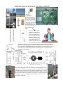
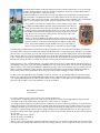
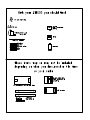
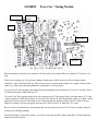
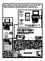
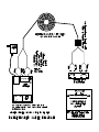
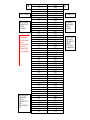
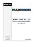
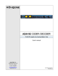
AM1000
INSTALLATION INSTRUCTIONS
OUTSIDE TRANSMITTER
AM1000
213 CARAWAY LN
Cary NC 27519
1
AM1000 QUICK INSTALL INSTRUCTIONS
Get Started!
Pick three locations 1) a
place for the transmitter
2) place for your studio
or inside connection (can
just be under a desk) and
3) a ground. Once you
have planned these locations so they will all
work together you are
ready!
First, put your transmitter
mount in, you can use standard 1 1/4 antenna mast
mount from Radio Shack or
an TV store. Be safe! Stay
away from electrical wires
and do not climb anything
unsafe! Remember the antenna needs to be in the free
air, not up against anything.
In Studio
Next do your cabling; if you have a balanced audio source you can connect the audio
pair directly to the transmitter, if you have an unbalanced (like a RCA jack) audio
source then use the AM1000PR adapter as shown. Plug in your audio to the 1/8 jack
on the adapter. Secure the control cable to the building or pole. Ground the control
wire shield at one end only.
Ground Rod
Now connect the ground connection. Connect the ground binding post at the
bottom of the transmitter to an acceptable ground. A good ground is important
so the lighting protection circuitry in the unit will function. Be sure to follow
any NEC or local codes, ground any mounting mast and/or mounts. The routing of the control cable is not important, it can just be tie wrapped to the mast,
or clamped to a wall. All connections need to be tight, so they won’t later
corrode from weathering.
Now mount the transmitter to the mast using the bracket (see bracket instructions). If you are not using
a bracket, install transmitter to wall or acceptable configuration. Install 102” Antenna (Radio Shack #
21-903) to the transmitter, it screws into the top.
Connect the audio/power wire as shown on first page diagram, the ground connects to the post at bottom of transmitter. Go ahead and connect power/audio and turn on. Be sure the power switch in the
transmitter is ON. If your unit is crystal - controlled be sure the crystal is installed (socket to the middle
right). If you are using the agile module, using the supplied chart, check your frequency.
Digital Volt Meter
It is possible to tune using the computer circuit, see the manual. Using a meter
(available from RangeMaster) place the red lead in the bottom of the three test
holes, the black lead in the top test hole, the middle hole is unused . The power
control (bottom left of board) should be up about 1/3-1/2 turn. (The control near
the middle of the board is the audio gain, turn it all the way down now for tuning). Set the meter to a low DC voltage, 10VDC, 20VDC is fine. This is the
meter setup to take the VOLTAGE.
There is a 11 position header to the right of the large round red coil. Keeping
your hands away from the antenna and coil best you can move the shunt up and
down the header, try to find the position that gives the highest reading on the
meter. This position should be near the middle of the range of the header. If
there are two places where the voltage goes up, select the one near the middle.
Then using the provided tuning tool, turn the 10 turn device (capacitor) screw just to the right of the shunt, try to increase
the voltage further. The goal is to find a peak voltage. You should be able to see the voltage go up, then down, as you rotate
the tool. If not, if you go all the way to the end of the travel of the 10 turns, try another shunt position. You need to find the
peak voltage in this step or you are not tuned and will not get good range. This tuning needs to be done when the transmitter
is in it’s final position, and with all connections stable. You can not tune the transmitter first on the ground, & then install it.
Find the peak voltage, & then leave it there. Now be sure to turn to audio level adjust pot back up.
Setting the power is easy, with the AM1000T “green light” simply rotate the power control until the LED at the bottom of
the transmitter turns green. If you don’t have the AM1000T ,just refer to the “power chart” at the back of the manual for the
proper readings of VOLTAGE and CURRENT combinations possible. VOLTAGE is read the same way as when you were
tuning, to take the CURRENT reading just place the black lead in the bottom test hole and the red lead in the middle test
hole, read the voltage on the digital meter. Rotate the power control until the readings are in line with the chart.
It’s best to leave the audio adjust in the transmitter at 3/4 level, or all the way up, and adjust audio level from the ground.
There is also a gain adjust in the AM1000PR audio adapter module. Adjust the audio level for good sound on a test radio.
Your signal should sound as loud as other stations in the area. Get the audio level as high as you can without distortion. Try
not to have the test radio to close to the transmitter, it can get overloaded.
RangeMaster Transmitters
(919)367-0607
If you have trouble feel free to call, but check a few common problem first:
-Is your audio level high enough? Is it on? Audio is a gate on the power, if there isn’t enough audio the range will suffer
-Check the voltage at the terminal block with your meter, is there at least 12 volts there?
-Low range is often a bad ground, it could be poor soil conductivity in you area, a broken ground wire, or your ground rod
could be in sand or gravel instead of dirt. This is common when using an electrical meter rod, and/or if the rod is to close to
a building foundation. If you can just push your rod in the ground it is probably just sand, and it won’t work. Connections
can’t just be wrapped and taped, they need to be clamped. Clamps can be found at the hardware store. The copper needs to
be bright and shiny and the tightly clamped or soldered. Use an 8 foot rod if possible. Isolate the ground wire from metal on
the way down.
-Be sure you set the power properly
-Be sure the audio pot is turned up
-Be sure the crystal is in
-Here is a way to check transmitter operation: temporarily turn power up, you can draw a small spark from one of the round
red coil leads or the antenna with a lead pencil if the unit is working correctly. If it is to bright out you may not see the spark
Please note that changes or modifications not expressly approved by RangeMaster for compliance
could void the user's authority to operate the equipment.
Installing the AM1000 transmitter
This unit is meant to be installed by someone who has some radio background. If you don’t
feel qualified to install this unit yourself contact a local radio/TV shop. They may be able to
help. Also if you have a friend who is a Ham radio operator they may be able to help you.
The goal of a successful installation is to achieve ½ mile range if the unit is near ground level.
Within this ½ mile the signal should be clear and easy to hear. There may be some static
mixed in, but the message being played should be clear. Up to a mile range and further may
be possible if you have a good site and have the unit higher. For good range the unit should
be the highest thing in the area.
Look around the structure and find a suitable place to mount the transmitter.
Keep in mind the cabling needs, a cable needs to run to the power and audio source. See
included diagram for cabling example. #24 (2) pair shielded cable can used for runs of 50
feet or less, #22 for up to 100 feet. Use one pair for + and – 12 volt and the other pair for the
600 ohm balanced audio. Connect the outer shield to ground at just one end. Also a ground
connection needs to be run from the transmitter to a good ground for lightning protection.
You can drive a 4 or better 8 foot ground rod into the ground for the lightning protection
ground or use an existing ground. For best lightning protection the ground connection should
have a direct path as possible to dirt ground.
If you get low range and the tuning peak voltage range is low you may have a bad ground.
Driving an 8 foot rod into soil should help you have a good ground. Don’t get the rod to close
to a house foundation. An electrical or pipe ground may not be reliable.
RF (radio frequency) can be tricky stuff. If you don’t get results from your site, try another. The
height is very important. The unit will not work unless it is tuned after it is installed in its final
position. (You can’t tune it on the ground first, it HAS to be tuned after everything is done,
wires tacked into position so that they will not move.
Avoid putting the antenna near metal, especially large massive pieces of metal. Small metal
pieces may be all right. You want to provide a stable environment around the unit.
The antenna develops hundreds of volts of RF power. It won’t shock you and can easily be
quenched by even putting your hand close to it.
Once you’ve found a site sturdily mount the unit to the structure. Cable the ground wire to a
good ground. The ground wire connects to the binding post on the bottom of the unit. If your
wire is to large to fit into the binding post use a short section of wire and a wire nut to
complete the connection. Weatherproof the wire nut connection. Cable the unit to the
inside to provide power and audio for the transmitter. See included diagram. The unit requires
2
a 102” whip antenna that can be purchased at Radio Shack, Stock # 21-903. It can be steel
or fiberglass. The striped wire is plus + on included wall power supply.
Begin the Tuning: You will need the following
Meter
Tuning tool (supplied)
Small flathead screwdriver
Medium Phillips screwdriver
The VOM or volt ohm meter can be bought at a Radio Shack if you don’t have one. Be sure
the crystal is installed if you are not using the agile module.
The crystal will not lock into the board, just seat it into the socket pins, it won’t fall out.
The following are instructions to tune with a meter, see Am1000T page to use the computer
tune process.
Check that “TUNE” is set 1/2 way between the counter- clockwise position (Min.
Capacitance) and clockwise position (Max. Capacitance). Use the tuning tool to tune. When
“TUNE” is turned fully either way be careful not to apply to much force. Permanent damage
may result. “TUNE” will turn about 10 turns. Make sure that the “Power Adjust” control is set to
about 1/2 of the way from counter clockwise. It is a 1 turn control. Set “AUDIO LEVEL” all the
way down (counter – clockwise). Important Note: (TURN IT BACK UP WHEN YOU ARE DONE
TUNING!) (This is a commonly missed item)
Set the “POWER SWITCH” to on. “Cabling note, you can use either terminal block for
cabling they are both the same, (+ and – is for power NOT S+ and S-, AF+ and AF- is audio)”
Check all of your cabling, turn the power on. You should be able to see the power light come
on. See cable diagram in this Manual for cabling examples. When using the control cable
Ferrite if the hole is to big try to loop the cable through twice. The ferrite installs on the audio
cable just outside the transmitter box.
Step 3
There are 3 test hole pads on the unit (see diagram). Take a standard voltmeter that is set to
DC 5-20 volts and plug it into the bottom and top test hole pads. The black lead will go to the
test hole pad closest to the mounting hole (Ground) (Top).
Next move the jumper on the “COIL TUNE” jumper block one at a time to find the one that
gives the highest meter reading or highest power amp voltage. Be sure that only one jumper
is used at a time. Leave this jumper on the highest meter reading and proceed. If you find 2
areas of the jumper block that give a peak reading one of them may be an harmonic. Chose
the position closest to the center of the jumper block range. If you are not seeing a good
meter reading then rotate the PWR control until you do, or check your meter.
Step 4
Now take the tuning tool and rotate “TUNE” to obtain a peak reading of the meter. When
the meter peaks you are tuned. Be sure to stay away from the antenna while tuning. If you
are to close to the antenna your body will affect where it tunes.
3
Keep in mind that you need to see a peak. The meter should rise and fall as you adjust. If you
just turn it clockwise or counter clockwise all the way and the meter goes up until the
capacitor can’t be turned anymore then it is not tuned.
You will get the most power with the least capacitance of the tuning cap that you can get to
tune (counter clockwise). You may find that 2 jumper positions will tune. If so use the one that
tunes with the “TUNE” in the most counter clockwise or least capacitance position. This will
give you the best range and circuit performance.
Step 5
The next step is to adjust the power level.
Automatic method, simply adjust the Power Control until you get the Green Light. Turn very
slowly.
The manual method involves simply involves taking 2 voltage readings and referring to the
power chart in this manual adjust the power pot until you are at the legal power level. Turn
the audio pot all the way down. Take your voltage reading, take this reading with the meter
leads in the same position as when you were tuning. Now place your Black (negative) test
lead in the bottom test hole pad & your Red (Positive) test lead in the middle test hole pad.
This will measure your Current.
Your power should not exceed 100 milliwatts or .1 Watt to comply with FCC rules (Part 15).
This would be acceptable. See the conversion table supplied for different combinations of
Voltage and Current that equal 100 milliwatts. The “Power Adjust” works just like a volume
control. Clockwise is more power and counter clockwise is less. Again with the AM1000T
“Green light” simply adjust Power level control until the LED is green.
Step 6
Next connect your audio source. It is a good idea to leave the “aud” audio adjust ¾ to all the
way up “clockwise” and adjust the audio level from the ground. The Terminal block input is
designed to work with a 600 ohm telephone cable like impedance. When you order the
AM1000 you get an adapter that will convert 8 ohm (low imp 3.5mm) speaker type output or
(high imp) like from a CD player to the required 600 ohm balanced audio. The new audio
adapter has a gain control.
Step 7
Using a test radio tune to the transmitter frequency. The frequency used for this unit is often
1610 Khz . If the frequency is different it will be marked inside the unit. Look on the crystal (Y1).
Once you pick up the signal on your test radio, (with no audio it will sound quiet with maybe
a slight hum. Turn up your “AUDIO LEVEL” while listening to the test radio until you get
distortion then back the “AUDIO LEVEL” off just a tad. If you are adjusting the audio level from
the ground leave the “AUDIO LEVEL” set about ¾ position. Your station should sound as loud
as others in your area on a test radio, if you don’t then there is a problem.
A scope is needed to be sure of 100% modulation. When the unit is being 100% modulated a
test sine wave at the antenna will match the original audio waveform. If you don’t have a
scope then just set the level for good sound.
4
Step 8
Now go and check your range. Use your car and your odometer to check the range. Do the
final tune on “TUNE” (Check to be sure the meter voltage is still peaked). Adjust “AUDIO
LEVEL” control for best sound on your radio.
Keeping the antenna as vertical as possible will help your range. It is also critical to keep the
antenna away from metal. Don’t for example, mount the antenna so it runs up against, or
parallel to a metal drain pipe.
Before you leave make sure that the customer knows that if they have any trouble with the
transmitter to simply unplug the wall transformer or power supply. Because of the high RF
voltage generated the unit can induce a signal into phone lines, stereos, and other
equipment.
If you find that you are not getting good range check the transmitter ground system, if you
notice that when tuning the unit that instead of a sharp peak in the voltage the voltage
barely moves while you are tuning you probably have a bad ground.
Electrical grounds
will not always be acceptable, you may need to run a separate ground or find another
ground. You could use a water pipe that is going to ground for example. Also if you are
getting poor range make sure you have set the power properly. If you are having troubles
recheck all wiring and connections. If you have carrier but no audio be sure the audio pot is
turned up. Be sure the power is connected to the power terminals and not the sync terminals.
Be sure the crystal is in and seated (unless you have the freq module). See the trouble page.
Section 15.219 Operation in the band 510 - 1705 kHz.
(a) The total input power to the final radio frequency stage (exclusive of filament or heater
power) shall not exceed 100 milliwatts.
(b) The total length of the transmission line, antenna and ground lead (if used) shall not exceed 3
meters.
(c) All emissions below 510 kHz or above 1705 kHz shall be attenuated at least 20 dB below the
level of the unmodulated carrier. Determination of compliance with the 20 dB attenuation specification
may be based on measurements at the intentional radiator's antenna output terminal unless the intentional
radiator uses a permanently attached antenna, in which case compliance shall be demonstrated by
measuring the radiated emissions.
We recommend fully cooperating with the FCC and following all FCC rules. The FCC is an independent governmental
agency, answerable only to congress, we cannot guarantee and/or we cannot be held responsible for what the FCC may do or
decide in any particular situation.
5
POWER
ADJUST
AM1000T
Module
(if
installed)
COIL
TUNE
Audio
Level
CRYSTAL
TEST
HOLES
6
CAP
TUNE
AM1000T
J13
Power Set / Tuning Module
Power
Adjust
LED
Coil Tune
Cap Tune
When transmitter is turned on, the computer will start in Power Set mode if there is a shunt in J13 (Power is set
last).
When you are tuning you will get better readings with the power all the way down (Power Adjust counter
clockwise). Also it will help if the Cap Tune (10 turn device) is about in the middle of it’s range (5 turns in from
either way). Please note the tuning function is an alternative to using a meter.
To go to the Coil Tune program (first tuning step) turn transmitter on with shunt in J13, wait 1-2 seconds, remove
J13 shunt, then replace shunt back into J13.
To use the Coil Tune program simply move the shunt on the Coil Tune jumper block, and then remove J13, if the
voltage is higher the LED will be green, if lower the LED will be red. Then immediately replace J13 shunt. At this
point you can move the Coil Tune shunt if you wish again and take another reading with J13. If the LED goes
blank (It is starting Cap Tune program) just turn power off/on with J13 in, then move J13 out/in.
Be sure to have your hands away from antenna and coil areas when you remove J13 to take a reading, otherwise
you may get confusing readings.
The goal in tuning is to peak the voltage, or to arrive at the peak possible voltage using the Coil Tune shunt and
tuning tool on the Cap tune.
To go to the Cap Tune program just leave the shunt in J13 for 15 seconds, the LED will turn off. Take the shunt off
j13 (and then replace shunt onto J13) and you are in the Cap Tune program.
To find the peak voltage using this program you need to get used to working with the program. As the voltage is
steady or going up the LED will remain green, it will however tell you when the voltage is going down, and how
fast. Turning the Cap Tune more quickly will give more red blinks as the voltage goes down.
When the voltage is dropping quickly the LED will be solid red, when the voltage is dropping slowly the LED will
tend to blink red. Of course as the voltage is going up (which is what you want) the LED will remain green.
So rotate the Cap Tune left or right, which ever way the LED stays green, until it starts to go red. Then rotate Cap
Tune the other way until the LED blinks red again. You should find as you rotate both directions that you can turn
about one full turn either way or so before the LED starts to blink red, leave the Cap Tune in the middle of the
green range and you are tuned!
Just keep in mind the LED blinks/goes red as the voltage is going down, and the goal is to keep the voltage going
up until you find a peak.
You may find using a voltmeter quicker, but if you don’t have a voltmeter handy this program will do the job.
Once you have tuned turn the transmitter off, then back on with a shunt in J13. This will put the computer in Power
Set mode.
Simply rotate the Power Adjust to light the LED green for .1 watt legal power level.
Example tuning:
Coil Tune shunt is on position 3
Coil Tune program running (see earlier instructions)
Move Coil Tune shunt to position 4
Remove J13, LED is green (voltage is going up)
Replace J13
Move Coil Tune shunt to position 5
Remove J13, LED is green (voltage is going up)
Replace J13
Move Coil Tune shunt to position 6
Remove J13, LED is red (voltage is going down)
Replace J13
Move Coil Tune shunt to position 5
Remove J13, LED is green (voltage is going up)
Replace J13
Move Coil Tune shunt to position 4
Remove J13, LED is red (voltage is going down)
Replace J13
Move Coil Tune shunt to position 5
Remove J13, LED is green (voltage is going up)
Replace J13
Coil Tune position 5 has the highest voltage.
Leave the shunt in J13 for 15 seconds (LED blanks, then remove J13) to move to Cap Tune program where you
continue peaking the voltage with the Cap Tune control. When the voltage goes down the LED will go red, when
the voltage goes down fast the LED will be solid red, when falling slowly the LED will be blinking RED.
If you are using an Innovonics 222 be sure your output polarity is correct, here is how:
1. Turn the positive peaks all the way down
2. Turn the output level up until you get distortion, then back off a little (hair) for good sound.
3. Then turn the positive peaks all the way up, if you get distortion then the (output) terminals + and - are
probably reversed.
The polarity of the input terminals doesn’t matter.
If you are having trouble matching your input impedance to the Innovonics see the website for instructions.
(How to hints, then audio button)
-Your station should sound as loud as others on the dial, if it doesn’t there is a problem. It may be an audio
impedance mismatch, or the level may need to be turned up. If the audio level isn’t high enough you won’t get
good range, audio is a gate on the power, keep your audio turned up as high as you can.
-We have found the most common cause of low range is the audio setup, even more common then grounding
problems. Not enough audio power (volume) and/or an impedance mismatch. If you are using an 8 ohm (low
impedance) output which would be a headphone or speaker output that needs to be connected to the low
impedance input on the audio adapter. Then the 2 screw terminal block needs to be wired via 2 wire twisted
pair to the transmitter. If you plug the low impedance port of the adapter to a high impedance source like a line
out jack you will have problems. An impedance mismatch will lower the audio level and reduce the fidelity, and
may cause distortion. If you have a line out type source it needs to go to the high impedance jack on your
audio adapter. In either case if you can’t get the audio loud enough so it is as loud as other stations in your
area without distortion then there is a problem in the audio chain.
To get more Range:
Try to locate the transmitter near something that will reradiate the RF energy such as high tension power lines.
The signal will tend to follow lakes and rivers. Use as high a modulation level as you can. Get the unit as high
as you can but not so high you can’t safely get to it to tune it.
Troubleshooting:
-Check the voltage at the terminals of the transmitter, is there at least 12VDC there?
-Low range is often a bad ground. There could be bad soil conductivity in your area, or the ground rod could
just be in gravel or sand instead of dirt. If you can just push the rod in with your hand then it won’t be a good
ground. Bad connections are often the problem. Just wrapping wire around a rod will NOT work. ALL
connections need to be soldered or clamped. The copper needs to be bright and shinny before soldering or
clamping. Use an 8 foot ground rod if at all possible. If you are using bigger then #10 wire (better) you won’t be
able to insert it into the binding post at the transmitter. Use a short (6”) piece of #12 as a splice make the
connection. Twist the #12 wire to the larger wire and twist a wire nut on. Be sure to weatherproof this with
some silicone. Then put the other end into the ground binding post of the transmitter and tighten the binding
post. If you find that you installation degrades after a few weeks you probably have a ground splice or
connection that is weathering or corroding somewhere. This ground wire must be locked down and stable so it
won’t move. Electrical grounds will not always be acceptable, you may need to run a separate ground or find
another ground. You could use a water pipe that is going to ground for example. See the hints page for an
example of a good ground system.
-Check quality of ground- After tuning unit, with the tune voltage at about 2-3 volts (rotate PWR) rotate the Cap
tune from the extreme counter clockwise position to the clockwise position while watching the meter. Make
note of the voltage swing you see, less then 1.5 volt, bad or no ground. 1.5-2 volts poor to adequate ground. 23 volts, good ground. 3-5volts, great ground. This test will give you an idea where you stand with your ground
quality.
-If you are getting poor range be sure you are setting the power properly.
-If you have carrier but no audio be sure the audio pot is turned up. Be sure the power is connected to the
power terminals and not the sync terminals.
-Be sure the crystal is in and seated (unless you have the freq module).
-Is power switch on?
-Are you using the tuning tool provided?
-When the transmitter is working properly it is possible to see a small spark with a pencil lead placed close to
the coil (large red round object) pins. You may need to turn the power up for it to do this. Or you may feel a
slight RF burn to your finger if you lightly touch the pins of the coil.
FEDERAL COMMUNICATIONS
COMMISSION
WASHINGTON, D.C. 20554
COPY
COPY
GRANT OF EQUIPMENT
AUTHORIZATION
Certification
Hamilton PCB Design
134 Wind Chime Ct. P.O. Box 20594,
Raleigh, NC 27619
United States
Date of Grant: 07/17/1998
Application Dated: 05/08/1998
Attention: Keith Hamilton
NOT TRANSFERABLE
EQUIPMENT AUTHORIZATION is hereby issued to the named GRANTEE, and is
VALID ONLY for the equipment identified hereon for use under the Commission's
Rules and Regulations listed below.
FCC IDENTIFIER:
Name of Grantee:
Grant Notes
37
NWXAM1000
Hamilton PCB Design
Equipment Class: Part 15 Low Power Communication Device Transmitter
Notes:
Frequency
Output
Frequency
Range (MHZ)
Watts
Tolerance
FCC Rule Parts
15C
Emission
Designator
1.2 - 1.71
37: This device has shown compliance with new rules adopted under Docket 87-389 and is not affected by Section 15.37, transition
rule.
Mail To:
9805218315166002
E
VOLTAGE
BOTTOM
AND TOP
TEST
JACKS
Note
This page
for Ref only
Use.
Turn Power
Look for
Green LED
to set power
READINGS
NEEDED
THAT
PRODUCE
100
MILLIWAT
TS
1.0
1.1
1.2
1.3
1.4
1.5
1.6
1.7
1.8
1.9
2.0
2.1
2.2
2.3
2.4
2.5
2.6
2.7
2.8
2.9
3.0
3.1
3.2
3.3
3.4
3.5
3.6
3.7
3.8
3.9
4.0
4.1
4.2
4.3
4.4
4.5
4.6
4.7
4.8
4.9
5.0
5.1
5.2
5.3
5.4
5.5
5.6
5.7
5.8
5.9
1.00
.910
.840
.770
.720
.670
.630
.590
.560
.530
.500
.480
.455
.435
.420
.400
.385
.370
.360
.345
.335
.325
.315
.305
.295
.285
.280
.270
.265
.255
.250
.245
.240
.233
.228
.223
.218
.213
.210
.205
.200
.197
.193
.189
.186
.183
.180
.177
.174
.171
I
CURRENT
MIDDLE
AND BOT
TEST
JACKS
1.00 VOLT
EQUALS
100 MILLI
AMPS
ACTUAL
CURRENT