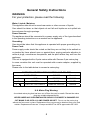
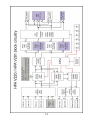
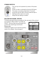
1
HEADPHONE AMPLIFIER
HPA V281
USERS MANUAL
1
Content
Theme
Page
About Violectric
Safety Instructions
The Earth / Grounding Concept
Connection / Connectors
General
Block Circuitry
Operation
Things to know
Disposal
Technical Data
Dismantling
Jumper Setting
Conformity Statement
Warranty
3
5
7
9
10
13
11
24
29
30
31
32
34
35
CAUTION !!
THE HIGH OUTPUT LEVELS ACHIEVABLE
WITH THIS UNIT MAY
DAMAGE YOUR HEARING OR THE HEADPHONES
IF OPERATED CARELESSLY !!
2
Cordial thanks for your decision in favour of a
product !
is a trademark and product line of Lake People
electronic GmbH. Lake People electronic GmbH develops,
manufactures and distributes products in the professional range, for
broadcast, television, airports, exhibition halls, festival venues, theatres,
large-scale installations, private studios and more. In the private sector
as well, Lake People products become increasingly popular due to their
outstanding quality.
The
trademark and product line is specially intended to
supply the Hi-Fi and High-End market with its specific requirements.
Who develops
equipment ?
devices are exclusively developed in Germany by the
engineers of Lake People electronic GmbH. In doing so, the team of
developers can draw on twenty years of experience and countless
products for the pro-audio domain.
Among others, the first German-made 20-bit A/D and D/A converters
were developed by Lake People in the early nineties of the past century.
Who manufactures
equipment ?
devices are exclusively manufactured in Germany by
Lake People electronic GmbH or contractors in the company's vicinity.
- put high emphasis
Lake People - and by association
on domestic manufacturing. As well, all component suppliers are chosen
in order achieve the main part of added value inland.
3
How do
devices get to the customer ?
devices can be obtained from respective specialist
suppliers. If there is none such accessible regionally, the customer is
supported by transregional distribution partners (google may help...)
and, of course, by Lake People electronic GmbH themselves.
… and if it doesn't work like it should ?
devices are covered by a 24-month warranty. In case of
any malfunction during this period, they can be shipped to the
manufacturer directly. Of course, the client will benefit from
's and Lake People's full technical support even when
warranty has expired. Any technical questions or need for advice is
welcome.
is a subsidiary of
LAKE PEOPLE electronic GmbH
Turmstrasse 7a
D-78467 Konstanz
Fon +49 (0) 7531 73678
Fax +49 (0) 7531 74998
www.violectric.de
www.lake-people.de
www.violectric.com
www.lake-people.com
4
General Safety Instructions
WARNING
For your protection, please read the following:
Water, Liquids, Moisture:
This appliance should not be used near water or other sources of liquids.
Care should be taken so that objects do not fall and liquids are not spilled into
the enclosure through openings.
Power Sources:
The appliance should be connected to a power supply only of the type described
in the operating instructions or as marked on the appliance.
Grounding:
Care should be taken that this appliance is operated with proper grounding only.
Power Cord:
Power supply cords should be routed so that they are not likely to be walked on
or pinched by items placed upon or against them, paying particular attention to
cords at plugs, convenience receptacles, and the point where they exit from the
appliance.
This unit is equipped with a 3-pole mains cable with German 3-pin mains plug.
In some countries this unit must be operated with a mains adaptor, supplied by
the owner.
Please refer to the table below to connect a mains plug:
OVERVIEW: POWER CORD FUNCTION AND COLORS
CONDUCTOR
E
COLOR
Alternativ
L
LIVE
BROWN
BLACK
N
NEUTRAL
BLUE
WHITE
PROTECTIVE EARTH
GREEN+YELLOW
GREEN
U.K. Mains Plug Warning:
A moulded mains plug that has been cut off from the cord is unsafe. Discard the mains
plug at a suitable disposal facility.
NEVER UNDER ANY CIRCUMSTANCES SHOULD YOU INSERT A DAMAGED OR
CUT MAINS PLUG INTO A 13 AMP POWER SOCKET. Do not use the mains plug
without the fuse cover in place. Replacement fuse covers can be obtained from your local
retailer. Replacement fuses are 13 amps and MUST be ASTA approved to BS 1362.
5
Mains Fuse:
The mains fuse of this appliance is soldered in place and accessible from the
inside only!!
A blown fuse may indicate an internal problem and should be replaced during
qualified servicing or repair work !!
Switchable Power Supply:
Connect this unit to the power source indicated on the equipment rear panel
only to ensure safe operation !!
This unit is provided with an internally settable mains supply for 115 / 230 V AC.
Service / Repair:
To reduce the risk of fire or electric shock, the user should not attempt to service the
appliance beyond the measures described in the operating manual. All other
servicing or repair should be referred to qualified personnel !!
VOR DEM ÖFFNEN NETZSTECKER
ZIEHEN!! PULL MAINS BEFORE
OPENING!! AVANT D´OUVRIER
RETIREZ LA FICHE MALE!!
Electromagnetic Compatibility
This unit conforms to the Product Specifications noted as Declaration of
Conformity at the end of this manual. Operation is subject to the following
conditions:
-
this device may not cause harmful interferences
this device must accept any interference received,
including interference that may cause undesired operation
this device must not be operated within significant electromagnetic field
6
The Earth / Grounding Concept
General GROUND-LIFT Jumper ( accessible from the inside.
Mind the SECURITY INSTRUCTIONS !! ):
Ex-works this jumper is set to the LIFT position.
The internal ground potential is “lifted” by means of this jumper.
As a result, the interconnection for DC voltages and lower frequencies
(< 150 Hz) will be cut. Higher frequencies will be bled off to earth
potential through the RC filter. The LIFT position is helpful in case of
7
hum or jitter caused by different ground/earth potentials.
Of coarse full electrical protection is granted as the case is always
connected to ground/earth potential !
See page 32 "Technical Appendix" for details.
Unfortunately there is no general recommendation how to solve hum
and jitter problems - or even minimize them. The best way to succeed is
to check different options !! In case of balanced cables, it should always
been verified if the shield of the cable is connected to the shell of the
XLR connector. The shell is ALWAYS connected to earth potential when
the connector is inserted !!
Concerning ANALOG inputs and outputs, the relationship between
ground and earth may be modified. Electrical safety is always ensured,
since the earth conductor is permanently connected to the enclosure !!
XLR GROUD-LIFT Jumper ( accessible from the inside.
Mind the SECURITY INSTRUCTIONS !! ):
G(ROUND): Ex-works all jumpers are set to "G" (ground) position.
Pin 1 is connected to the internal ground reference.
High frequency interference is deflected to the case via a
100 nF capacitor.
L(IFT):
The interconnection between Pin 1 and ground is open.
High frequency interference is deflected to the case via a
100 nF capacitor. This jumper position is specifically
useful if the unit is equipped with transformers !!
C(ASE):
Pin 1 is connected to the case, the 100 nF capacitor is
bridged. This jumper position may be varied together with
the General GROUND-LIFT jumper.
Please note that with jumpers not in the ex-works position
EMC emission might occur,
for which the user is responsible only !
8
Connection / Connectors for Analog Signals
9
GENERAL INFORMATION
The HPA V281 is a stereophonic headphone amplifier designed to drive
low-, medium- and high-Z loads (16...600 ohms) as usually represented
by high-quality headphones.
Because of its 4 built in amplifiers and the 4-pin XLR socket on the front
it is also suited to connect balanced headphones.
Due to its specific, variable and low-noise and distortion circuit design
especially optimised for dynamic headphones, the HPA V281 fulfils
even highest demands.
Features:
-
Balanced inputs with gold-plated Neutrik XLR connectors
Unbalanced inputs with gold-plated premium RCA connectors
Digital input as an option, coaxial, optical, USB, up to 192 kHz
inputs selectable on the front panel
PRE-GAIN = switchable input gain in five steps
Balanced and unbalanced line outputs with RCA resp. XLR sockets,
gold plated, pre-post fader assignable
Independent-channel design
ALPS RK27 High-Grade volume control
Remote controlled and motorized volume control, input/output selection,
mute as an option
High-Quality op-amps in the signal path
High-quality MKP capacitors in the signal path
0.1 and 1% metal film resistors throughout the unit
-
4 Discrete-design power amps with 8 transistors per channel
Output management: headphones active /
line-out active / both active / none active (mute)
2 silver-plated Neutrik headphone outputs
1 4-pin XLR socket, gold plated for balanced headphones
delayed relay-based headphone output cut-off
2 x Toroidal transformers, 25 + 15 W
Large filtering capacitors in the power supply (36.000 uF)
-
Switchable ground lift
Rugged aluminium case with Nextel coating
Solid, laser-engraved aluminium front panel
-
10
With its small dimensions, the HPA V281 ensures optimum flexibility
combined with high output power. During design, high emphasis was
put on operational safety even when the unit is operated inappropriately.
The HPA V281 is equipped with internal filters to prevent damage to the
connected headphones due to high-frequency overload beyond the
audible range.
THE CASE
The HPA V281's case as well as the front / rear panels are made of
solid aluminium. This choice of material ensures high mechanical
stability and resistance.
EARTH AND GROUND
The HPA V281's case is grounded. Internal reference ground is set to
“LIFT” position ex works but may be reconfigured to “GROUND” position
if required. ( see also: page 7 "Earth/Ground concept", page 32
"Technical Appendix" ).
POWER SUPPLY
Mains power is provided via a three-pin IEC/CEE socket and mating
"cold-appliance" mains cord with Schuko-type plug for units purchased
in middle Europe.
The device is set to 230V mains, whereas the actual voltage may vary
between 190 and 240 volts for flawless operation.
The mains voltage may be altered to 115 V AC supply inside the unit
with the aid of a mains voltage selector. In this case stable operation is
granted in a range of 85 to 120 V (see page 32).
Two toroidal transformers with 15 and 25 Watt are providing the internal
operating voltages of +/-30 V. Out of these voltages some more
operating voltages are generated.
11
MAINS FUSE
The 0.25A time-lag fuse is soldered in place on the circuit board. In
case, it must be replaced with a fuse of the same type only.
CAUTION !!
MIND THE SAFETY INSTRUCTIONS:
A blown fuse indicates an internal fault and
should be replaced during qualified repair or
servicing only !!
12
13
POWER SWITCH
The unit is put into operation by means of the power
switch.
Power-on status is indicated by the blue LED below.
The power-on procedure takes about 5 seconds.
During this time the LED of the last selected input is
flashing and the outputs are muted.
Always the last setting is recalled.
BALANCED SIGNAL INPUTS
The balanced signal inputs are situated on the rear panel of the unit and
are labelled as "BAL IN LEFT" and "BAL IN
Balanced XLR
RIGHT". They are fitted with gold plated XLR
Pin-out:
sockets with metal flange from Neutrik.
PIN 1 GND
Please note:
PIN 2 (+) PHASE
Unbalanced signals can be injected as well by
PIN 3 (-) PHASE
means of an adaptor. Also see page 9.
14
UNBALANCED INPUTS
For the use with unbalanced signals, gold plated premium RCA sockets
are provided. They are labelled as "UNBAL IN LEFT" and "UNBAL IN
RIGHT".
Input impedance for all inputs is 10 kohms.
Maximum input level should not exceed +21 dBu.
This value is reduced to +15/+9 dBu if PRE-GAIN is set to +6/+12 dB !!
THE OPTIONAL DIGITAL INPUT
Currently the HPA V281 can be fitted with one out of six D/A converter
types, with three different inputs and a max. sample rates of 96 or 192
kHz:
The COAX input accepts digital PCM audio data in S/P-DIF format, at
sample rates from 28 to 108 kHz (or 210 kHz resp.).
The OPTO input, fitted with a TOS-LINK interface, accepts digital audio
data at sample rates from 28 to 108 kHz (or 210 kHz resp.).
The USB type “B“ input can be connected to a host computer (PC or
laptop). The USB module will automatically be detected as an audio
device.
The USB 96 input is compatible with USB 1.1 and 2.0 standards. It
accepts digital audio formats up to 24 bit at sample rates of 44.1, 48 and
96 kHz, while 88.2 kHz is not supported.
The USB 192 input is compatible with the USB 2.0 standard. It requires
a proprietary driver, which can be downloaded from www.violectric.de.
Digital audio formats up to 24 bit at sample rates of 44.1, 48, 88.2, 96,
176.4 and 192 kHz are supported, as well as the so-called
“asynchronous mode”.
The 96 kHz digital modules comprise a D/A converter with a dynamic
range of 110 dB and –100dB THD+N, thus ranging in the upper-mid
performance class.
The 192 kHz modules are equipped with a top-notch converter offering
a 115 dB dynamic range and –103 dB THD+N, along with significantly
improved analog output circuitry.
15
NOTES:
- After inserting the USB connector, it may be necessary to close
and restart running media applications on the host computer.
- Volume of the host application should be set to 100%.
INPUT SELECTION / ACTIVATION
By means of the “XLR / RCA / DIG“ pushbuttons on the HPA V281’s
front panel, either of the analog inputs or the digital input (if present) can
be activated. The LED next to the corresponding button will light up
accordingly.
Inputs can also be switched by means of the remote control:
- press “1“ on the remote control to select the XLR input
- press “2“ on the remote control to select the RCA input
- press “3“ on the remote control to select the DIG input.
Alternatively, the “channel up/down“ rocker button or “up/down” on the
directional pad can be used to step inputs through.
16
THE VOLUME CONTROL
The desired volumes for left and right channel are set simultaneously by
means of the “VOLUME“ control.
Volume can also be set via remote control. For this purpose, the volume
control is actuated by a servo motor. Manual operation of the knob at
the same time is possible without the risk of damage (although not
useful…).
Press the rocker button “Volume Up/Down” in order to increase or
decrease volume. Pressing “left/right” on the directional pad will have
the same effect.
BALANCE CONTROL
is provided to compensate moderate level differences between left and
right channel. These may root in the recorded material itself, noticeable
differences between left and right headphone system, or differences in
the user’s individual hearing.
All of the above can be carefully compensated.
The balance control offers a precise center detent in case no adjustment
is necessary. In order not to impair the V281’s perfect crosstalk specs, it
takes effect on the right channel only.
THE AMPLIFIER
The input signals are fed to an amplifier stage especially designed for
this application, with eight transistors per channel. The V281 houses no
less than four of those ! Channels are physically separated from each
other to ensure optimum crosstalk rejection.
The frequency range covers 5 Hz ... 70 kHz (-0.5 dB) or 3 Hz…200 kHz
respectively (-3 dB), in order to ensure fully linear performance within
the entire audible range. Overall gain is set to +8 dB (unbalanced) or
+14 dB resp. (balanced) to ensure sufficient volume reserve also for
high-impedance headphones.
17
Too loud ? Too soft ? The PRE-GAIN method
The V281 is specially designed to drive headphones. Headphones
however can present load impedances from 8 to 2000 ohms and
efficiency ratios from 85 to 115dB per milliwatt. Thus it can be quite
tricky to fulfil all demands, since...
… owners of high-efficiency headphones will rarely set the volume
control higher than 9 o'clock in order to exclude hearing damage, while
... the maximum setting may still be too soft for low-efficiency
headphones, but
… all users expect highest quality at lowest noise and distortion.
Thus, the circuitry must adapt itself as the headphone won't !
WE CALL THE SOLUTION TO THIS PROBLEM PRE-GAIN
The alignment between amplifier and headphone is provided by the
preamp stage, which can boost or attenuate the input signal in four
steps of 6dB each. For this purpose, two switching devices are located
on the rear panel for left and right channel individually.
CAUTION !!
The switch settings should be altered under the following conditions
only:
- The unit must be switched OFF
- the "VOLUME" control must be set to minimum
- left and right channel settings should ALWAYS be set the same
never increase the setting by more than ONE switch per channel
If you find your HPA V281's volume could be somewhat softer (in order
to improve volume control range e.g.), push the switch labelled "-6 dB"
(half gain) or "-12 dB" (quarter gain) in upward direction.
If you find your HPA V281 should provide more gain, do so with the
switch labelled "+6 dB" (double gain) or "+12 dB" (quadruple gain).
Ex-factory, all switches are set to their lowest position - i.e. 0 dB or unity
gain - which should be sufficient for most applications.
18
DE- / ACTIVATING THE HEADPHONE OUTPUTS
The headphone outputs can be activated
or deactivated by pressing the “HEAD“
button on the front panel.
The green LED displays the activated
status.
This function can also be switched via
remote control.
Press „RED“ ( the red button).
THE BALANCED HEADPHONE OUTPUT
The HPA V281 offers a balanced headphone output.
This is equipped with a gold plated female 4-pin XLR connector.
Balanced Headphone socket pin-out:
Pin 1
(+) Left channel
Pin 2
(-) Left channel
Pin 3
(+) Right channel
Pin 4
(-) Right channel
UNBALANCED HEADPHONE OUTPUTS
The HPA V281 offers two stereophonic headphone outputs, each
equipped with a 1/4" (6.3mm) jack socket.
Because HPA V281 offers 4 channel amplifier (2 x stereo), each socket
is driven by a dedicated stereo amplifier
Please note: the RIGHT
Unbalanced Headphone
phone jack is connected to the
socket pin-out:
in-phase stereo signal,
TIP
Left channel
whereas the left phone jack is
RING
Right channel
connected to the 1800 phase
SLEEVE
GND
shifted signal.
19
On power-up and power-down, the outputs are cut from the amplifier
circuitry by relay.
THE BALANCED LINE OUTPUTS
are located on the rear panel of the unit and are marked as “BAL OUT
LEFT” and “BAL OUT RIGHT”. Gold-plated, metal-flange Neutrik XLR
connectors are implemented here.
Hint:
With a balanced-to-unbalanced adapter this connection may also be
used for unbalanced cables. PLEASE NOTE THAT IN THIS CASE PIN
3 HAS TO BE LEFT OPEN ! See also page 9 for details.
Balanced interconnection
of the XLR socket:
Unbalanced interconnection
of the XLR socket:
PIN 1
GND
PIN 1
GND
PIN 2
in PHASE
PIN 2
Signal
PIN 3
out of PHASE
PIN 3
OPEN !!
20
THE UNBALANCED LINE OUTPUTS
are located on the rear panel of the unit and are marked as “UNBAL
OUT LEFT” and “UNBAL OUT RIGHT”. Gold-plated premium RCA
connectors are implemented here.
ACTIVATING / DEACTIVATING THE LINE OUTPUTS
The line outputs can be activated and
deactivated by means of the “LINE“
pushbuttons on the front panel.
The green LED indicates the activated
status.
This function can also be switched via
remote control:
Press “GREEN“ (the green button)
PRE-POST FADER or FIXED-VARIABLE
The line-out signal can be tapped at two different points within the
V281’s signal path.
If you wish to make use of the input signal without any level change –
for a device with its own level controls or recording purposes e.g. – the
Fixed-Out or Pre-Fader path (prior to level control) is the right choice:
In this case, the unaltered INPUT signal (prior to level control) is
forwarded to the line output.
If you want to feed a power amplifier or active loudspeakers, VariableOut or Post-Fader (including level control) should be used.
In this case, the line output provides the signal at the level set by the
volume control.
The V281’s line output offers further possibilities:
- balanced-in to balanced-out
- unbalanced-in to balanced-out
- balanced-in to unbalanced-out
- unbalanced-in to unbalanced-out
21
PLEASE NOTE:
It is generally possible to use the unbalanced and balanced outputs
simultaneously, but slight sound deterioration might occur depending on
the following devices connected. In order to ensure optimal sound
quality, only one output type should be made use of at a time.
Switching between “Pre“ and “Post“
is effected via software:
Press and hold the “LINE“ pushbutton
for about two seconds until the green
LED starts flashing. The present status
is displayed by the “XLR” LED (pre
fader) or the “DIG” LED (post fader).
The setting can be altered now by
pressing the corresponding button. To
complete the setting procedure, just
press and hold the “LINE” button again
until the green LED stops flashing.
LINE-OUTPUT LEVEL
can be set by means of internal DIP switches located on the line-out
circuit board. See page 33 for further details.
Generally, the level at the unbalanced output will equal the input level in
pre-fader mode, or with the level control set fully clockwise in post-fader
mode. By means of the DIP switches however, relative attenuation/gain
can be set to –12, -6, 0, +6 or +12 dB.
Please note that output level at the balanced output is generally +6 dB
higher than at the unbalanced output.
THE “MUTE“ FUNCTION
serves to mute ALL outputs. On the V281, it can only be activated via
remote control.
22
Muted status is indicated by the red “MUTE“ LED. The activated / deactivated status of the amp´s outputs however - as indicated by the
green LEDs - remains unchanged !
ERROR EVALUATION
In order to guarantee flawless operation and optimum protection of your
valuable headphones, the V281 is equipped with various protection
circuits:
- the delayed activation of the headphone outputs upon power-up
prevents your headphones from potentially adverse signal peaks
from the preceding circuitry.
In a similar manner, the headphone outputs are instantly
disconnected when turning power off.
- Adverse DC voltage should be kept from your headphones at all
times. If DC is detected, the headphone outputs will be
disconnected, indicated by the red “MUTE” LED flashing and the
green “HEAD” LED lit. The detection interval is about five seconds.
If DC disappears during this period, the unit will resume normal
operation automatically.
- Overloading (i.e. increased distortion) must be avoided in favour of
your headphones as well. If overload is detected, the headphone
outputs will be disconnected, indicated by the red “MUTE” LED
flashing and the green “LINE” LED lit. The detection interval is
about five seconds. If overload conditions resolve during this
period, the unit will resume normal operation automatically.
FACTORY RESET
of all software based settings can be done by pushing the “XLR” button
during powering up.
23
Things to know …
Why makes it sense to make such huge efforts ?
A headphone amplifier is a device designed to condition audio signals
with regard to the very specific requirements of headphones. This
doesn't sound too spectacular at the first glance and can be achieved
relatively easily. As with many things however, the devil is in the details
and much more effort is required to design one amplifier for all current
headphone models.
Headphones per se are quite diverse, and there are two essential
parameters: impedance and sensitivity.
In general, headphones with higher impedance can be regarded as less
sensitive than headphones with low impedance (which is not generally
true, but in the majority of cases). The sensitivity of headphones is
usually stated in dB (sound pressure level) per Milliwatt.
Extremes in this sense are the AKG K1000 with 74dB/mW on the one
hand, and the Sennheiser HD25 with108 dB/mW on the other hand:
The K1000 requires 2500 times the power to achieve the same sound
pressure as the HD25.
There is also the fact that headphones with high impedance usually
require much higher voltage to achieve high loudness. Thus the
amplifier must be designed with high internal supply voltages.
Which advantages do balanced signals offer ?
In contrast to unbalanced signals, balanced signals are carried by two
wires (plus ground/shield). In the transmitting device, a balanced signal
is created by generating an inverted original signal (180ˆphase shifted).
The "hot" wire carries the original signal (a), the "cold" wire the inverted
signal (-a). In the receiving device, the balanced signal is processed by
a differential amplifier, which detects the difference between both:
(a) – (-a) = 2a.
On its way between devices, the useful signal can be affected by
interference (s). Interferences however are in phase on both wires and
fed to the differential amplifier as well. Again, the amplifier detects the
24
difference between the interference contents: (s) – (s) = 0. Thus - in an
ideal situation - all interference on the signal path is eliminated.
Why are discrete signal paths important ?
Twin op-amps are the most common design for operational amplifiers,
i.e. two amplifier circuits are integrated in one device. If left- and rightchannel signals are processed simultaneously by such a device,
interaction between both cannot be excluded. This interaction is
admittedly diminutive, but should be avoided whenever a different
design offers the possibility.
Why are op-amps ideal for low-level signal processing ?
Discrete amplifiers (designed with transistors) are very popular in highend audio design also for preamplifier stages. This is often marketed as
an optimization measure, but the partially exorbitant extra expenses are
of course to be paid by the customer. But an op-amp consists of
transistors as well...
Moreover, its structure has the advantage of thermal coupling between
its internal components. Also ageing issues play a much less important
role. Due to the large number of op-amps types offered, it is possible to
pick an optimum type for any specific application.
Why does PRE-GAIN make sense ?
Two extreme examples (with the HPA V281 at +14 dB gain (x 4,5),
volume control set to full):
1st example:
The (pre-) amplifier provides 2V output voltage, whereas the headphone
requires only 2V for 100 dB sound pressure level.
With the control fully turned up, the V281 would deliver 9 V output at
+14 dB gain. Therefore the volume control would have to be operated
very carefully in order to avoid hearing damage. Moreover, any
interference at the input should be avoided since it would be
"unforgivingly" amplified as well. With PRE-GAIN, the input level can be
25
reduced by 12 dB (a fourth), with 0,5 V instead of 2 V input as the result.
This 0,5 V is again amplified by 4.5, then equalling 2.25 V. Now the
volume control can be turned over almost the entire range.
2nd example::
The (pre-) amplifier provides 1 V, whereas the headphone requires 20 V
to release 120 dB of sound pressure.
With the volume control fully clockwise, the V281 would provide 4.5 V at
+14 dB gain only - much too low for the headphone. By means of PREGAIN, input level can be boosted by 12 dB (four times), resulting in
effective 4 V input voltage instead of 1 V. These are again multiplied by
4.5, now equalling 18 V. This is still not enough, but far closer to the
optimum value.
Why does frequency bandwidth limiting make sense ?
In signal processing, sound is represented by AC voltages. Sound is
audible - for young people - from about 20 to 20000 Hz. The elder the
listener, the less he will hear high frequencies in particular.
In order to transmit these frequencies at optimum quality, the frequency
response of an amplifier should be as wide and as "flat" as possible. At
the low end of the scale, this limit is represented by DC, as there is no
frequency lower than zero. In upward direction, the limit can be set to
practically any frequency, but the higher, the more susceptible the
device becomes concerning electro-magnetic interference. This is not
audible in the first place, but may interfere with the useful signal and
then become evident. Therefore, unrestricted frequency response
attests thoughtlessness rather than remarkable engineering skill.
Why is a good volume pot essential ?
A volume potentiometer is a mechanical control element, which can be
obtained on the market at any low price. Meanwhile it is often replaced
by electronic circuitry, exhibiting essential disadvantages concerning
dynamic range, noise and distortion.
26
Conductive-plastic resistive tracks, high-quality multi-tap wipers and
separated chambers for the individual sections are highly desirable for
sophisticated applications, and high quality is inevitable to ensure
trouble-free operation for years. Since the market for really good pots is
a small one, manufacturers like Noble or Panasonic don't offer these
any more. A current sample of top of the line pots is the RK27 by ALPS,
which is also used in your HPA V281.
Why is a low output impedance essential ?
When actuated, electro-dynamic systems respond with a counterforce.
When the voice coil of a headphone has been displaced by the signal,
an (error-) current will be induced when it swings back to its initial
position. This current must be suppressed as far as possible, which is
effected best if the amplifier's output impedance is the lowest possible.
The damping factor describes nothing but the ratio between output
impedance of an amplifier and a given load.
Since there is no known technical specification, we define the load
(voice coil impedance) as 50 ohms. With V281 having an output
impedance of <0.2 ohms in balanced mode and <0.1 ohms in
unbalanced mode this results in a damping factor of 250 (balanced) and
damping factor of 500 (unbalanced).
Why are high supply voltages essential ?
A headphone doesn't really require high power, but from the equation
P = U2 / R we can see that the square of the supply voltage determines
the power into a given load resistance. The higher the headphone's
impedance, the more voltage will be needed. But this deals with the
achievable loudness to a limited extent only: Technically spoken, music
lives on fast transients which put high demands on signal processing.
And thus a fast transient can easily push an average amplifier with +/-15
volts supply to its limits (90 % of all headphone amps in the market are
operated with these or even lower supply voltages). Due to the high
supply voltage and the balanced operation mode of V281 you will
benefit from more than 4 x output voltage swing capability compared to
27
“standard” amps.
Why does a relay make sense when switching power ?
Amplifiers generate unwanted output signals when applying or removing
power, which can damage the connected headphones. The relay breaks
the connection between amplifier and headphone and thus protects the
latter until electrical conditions have stabilized.
Some words about the different digital input options.
At the moment there are 6 different digital inputs for the V281.
These offer coaxial, optical or USB inputs and accept up to 24 bit digital
data.
Coax & Opto 96 accept sample rates up to 110 kHz, the USB 96
accepts 44.1, 48 and 96 kHz, please note: NO 88.2 kHz. The USB 96
input is compatible to the USB 1.1 and 2.0 standard.
All the above modules own a D/A converter which we would judge to be
“upper middle class” with a dynamic range of 110 dB and THD+N at 100 dB.
Coax & Opto 192 accept sample rates up to 210 kHz, the USB 192
accepts 44.1, 48, 88.2, 96, 176.4 and 192 kHz and supports the so
called “asynchronous mode”.
The USB 192 input is compatible with the USB 2.0 standard. It requires
a proprietary driver, which can be downloaded from www.violectric.de.
The above modules are equipped with a top notch D/A converter with a
dynamic range of 115 dB and THD+N at -103 dB, along with
significantly improved analog output circuitry.
Which USB devices can be connected to the HPA V281 ?
Connections can be established to table-top or laptop PCs. MP3 players
or similar gear cannot be connected.
28
Why does 100% host volume setting make sense ?
Volume control within the host is always accomplished digitally, i.e. bits
are removed from the data stream. This may affect the signal quality
because the resolution will become lower and the distortions may rise.
In practise those effects will appear at such low levels which will not
allow a valuation of the signal quality
DISPOSAL
Disposal of Old Electrical & Electronic Equipment (Applicable in the
European Union and other European countries with separate collection
systems)
This symbol on the product or on its packaging indicates that this
product shall not be treated as household waste.
Instead it shall be handed over to the applicable
collection point for the recycling of electrical and
electronic equipment.
By ensuring this product is disposed of correctly, you
will help prevent potential negative consequences for
the environment and human health, which could
otherwise be caused by inappropriate waste handling of this product.
The recycling of materials will help to conserve natural resources.
For more detailed information about recycling of this product, please
contact your local Civic Office, your household waste disposal service or
the shop where you purchased the product.
29
TECHNICAL DATA HPA V281
All Measurements RMS unwtd., 20 Hz - 20 kHz, Pre-Gain set to 0 dB
Inputs:
Max.input voltage:
Input impedance:
Line outputsd:
Nominal input sensitivity:
Amplifier gain:
PRE-GAIN:
Frequency range:
Output impedance:
Damping factor (Load 50 Ohm):
Dynamic range:
Noise:
THD+N (1kHz/2x10V/100R = 1W)
THD+N (1kHz/2x4V/32R = 0,5W)
Crosstalk:
Headphone outputs:
2 x XLR female, balanced,
2 x RCA, unbalanced
1 x digital (Option)
+ 21 dBu, Impedanz 10 kOhms
10 kohms
2 x XLR male, balanced
2 x RCA unbalanced
+6 dBu
+8 dB unbal. / 14 dB bal.
-12 / -6 / 0 / +6 / +12 dB
5 Hz ... 70 kHz (- 0,5 dB)
3 Hz … 200 kHz (-3 dB)
< 0,1 Ohm unbal. / < 0,2 Ohm bal.
500 unbal. / 250 bal.
> 129 dB (A-wtd)
< -95 dBu (A-wtd)
< -102 dB / < 0,00079 %
< -100 dB / < 0.001 %
-105 dB (1 kHz) / -103 dB (15 kHz)
1 x 4-pol XLR
2 x ¼“ (6.3 mm) Phone Jack
Max. output level:
RL
(x 2 )
Ua
(dBu)
Ua
(V)
Pa
(mW)
(1kHz / < 0.1% THD+N)
600
34,3
40,2
2700
Balanced operation
100
29,7
23,7
5600
Both channels driven
50
25,4
14,5
4200
32
21,7
9,5
2800
16
16,0
4,9
1500
Power supply:
Case, Front, Back:
Dimensions:
230 V AC / 115 VAC max. 40 VA
Aluminum
170 x 112 x 320 mm (B x H x D)
30
Dismantling / Jumper Setings
Please note:
In the following, the internal settings of the HPA V281 are discussed.
For changing these, a TORX T10 screwdriver or a 3mm Allen Key is
required and you should by all means
PULL THE MAINS PLUG !!!
Only thereafter the settings can be altered without any hazard.
Dismantling
1. screw off both upper screws on the front panel
2. screw off both upper screws on the back panel.
3. unscrew both lower screws on the front panel by a few turns
in order to tilt the front panel a bit
4. now lift the upper lid
5. make your personal jumper settings
6. reassemble the unit in reverse order
To modify the Ground-Lift setting on the main PCB, you must also
disassemble the Line-Out PCB on top
31
JUMPER SETTINGS HPA V281
32
JUMPER SETTINGS HPA V281
33
EU CONFORMITY STATEMENT:
We herewith declare that the following unit
Name:
VIOLECTRIC HPA V281
Serial No. :
-all -
is in conformity with the following EC directives:
2006/95 EG
2004/108 EG
EN 60065
JIS C 6065
Low voltage directive
Electromagnetic compatibility
Security directives for audio-,
video- und similar electronic devices
For verification of conformity with regard to electromagnetic compatibility the
following harmonized standards are applied:
EN 50081-1 : 1992
EN 50082-1 : 1992
Generic emission standard
Generic immunity standard
Product family standard for audio, video, audio-visual entertainment apparatus:
EN 55013 : 2001
EN 55020 : 2002
EN 61000-3-2 : 2000
EN 61000-3-3 : 1995
This declaration is given under responsibility of:
LAKE PEOPLE electronic GmbH
Turmstrasse 7a
D-78467 Konstanz
Fon +49 (0) 7531 73678
Fax +49 (0) 7531 74998
Konstanz 18.06.2014
Fried Reim
34
CEO
WARRENTY
Since 1986 we are constructing and manufacturing sophisticated
electronics for ambitious customers.
Since the early beginnings we are trying hard by accompanying
measures, the use of 1st choice components and multiple quality
checks during production to avoid faults at large.
We are quiet effective in that and this is – amongst others - why we
enjoy such a good reputation.
Despite all accurateness faults may appear which may derogate the
proper operation of your product.
In this case your unit is protected by a 5-year Warranty !
Needless to say that we will care for your product even after the
expiration of the warranty. If it is necessary please dispatch your item to:
Lake People electronic GmbH
Turmstrasse 7a
D-78467 Konstanz
Fon +49 (0) 7531 73678
Fax +49 (0) 7531 74998
E-Mail [email protected]
Your warranty claim begins with the date of purchase, which should be denoted on your
proof of purchase.
Do not forget to include the receipt of sales or a copy of the receipt.
Please also include a short description of the fault(s).
For the reshipment we need you correct address !!
Care for a safe packaging. Best is to use the original packaging.
Please keep in mind that we cannot accept collect freight.
We will grant a quick repair and quick return of the unit.
In case of a warranty repair we will reship free of charge.
Please denote here the serial number and the date of purchase:
Serial Number
Date of Purchase
35
Additional gear from
HEADPHONE AMPLFIERS:
HPA V90
HPA V100
HPA V181
HPA V200
HPA V220
HPA V281
D/A CONVERTER:
DAC V800
PHONO PRE-AMPLIFIER:
PPA V600
LINE PRE-AMPLIFIER:
PRE V630
36