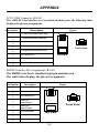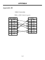
1
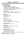
USER MANUAL
SHDTU03
NTU/E1
SHDTU03-NTU/E1 SHDSL Modem
Installation and Operation Manual
Version 1.1
Revision Marks
Revision
Date
Notes
V 1.0
V 1.1
N/A
2003.10
Software: Version: 1.5X7001r-XAT0
Auto-configuration added
Software: Version 1.19 FW: 2.2
Table of Contents
Chapter 1. Introduction … … … … … ..… … ....................
I. Features … … … … ...… ..… ...… … … … … … … … … … … … 1-1
II. Specification… … … … … … … … … … … … … … … … … … 1-2
III. Application. … … … … .… … … … … … … … … … … … … .. 1-3
Chapter 2. Hardware Installation … … … ....................
I. Front Panel ..… … ...… ..… ...… … … … … … … … … … … …
2-1
II. Rear Panel… … ...… … … … … … … … … … … … … … … …
2-3
III. Hardware Installation .… … … … … … … … … … … … … .. 2-4
Chapter 3. What's Auto Configuration … ....................
I. Wet Current ..… … ...… ..… ...… … … … … … … … … … … … 3-1
II. AIS (Alarm Indication Signal)… … ...… … … ..… … … … … 3-1
Chapter 4. Configuration with Keypad and LCD .… .
I. Purpose … ....… … ...… ..… ...… … … … … … … … … … … …
4-1
II. How to use key pads ?… … ..… ...… … … … … … … … … … 4-1
III. Menu Tree … … … … ...… … … … … … … … … … … … … .. 4-2
1. Menu tree for SHOW STATUS… … … ..… … ..
2. Menu tree for SHOW STATISTIC.....… … … ..
3. Menu tree for SETUP TYPE… … … ..… … … ..
4. Menu tree for SAVE CONFIGURATION… ....
5. Menu tree for DISGNOSTIC..… ..… … ..… … ..
i
Table of Contents
Chapter 5. Configuration with Console Port .… ..… .
I. Login Procedure … ..… ..… ...… … … … … … … … … … … … 5-1
II. Window structure… … … … .… ...… … … … … … … … … … 5-2
III. System Management Terminal(SMT) … … .… … … … … .. 5-3
1. Menu Command ...… … … … ... … … … ..… … ..
2. Navigating the SMT interface… … .....… … … ..
IV. Main Menu Summary … ..… … … … … … … … … … … …
5-5
V. Changing the password and user profile… … … … … … …
5-6
VI. Configuration the SHDSL NTU … … … … … … … … … .. 5-9
1. Configure SHDSL type… … … … … … ..… … ..
2. Configure SHDSL parameters… .......… … … ..
3. Configure E1 parameters… … .… … ..… … … ..
4. Restore factory default … … … … … … … ..… ..
VII. Write the setup parameters.… … … .… … … … … … … … 5-22
VIII. Reboot the SHDSL NTU.… … … ..… … … … … … … … 5-23
IX. View the system status … .… … … … … … … … … … … ..5-24
X. View the system configuration .… … … … … … … … .… .. 5-26
XI. Upgrade the SHDSL NTU.… … … ..… … … … … … … … .5-27
XII. Diagnostic … .… … … … … … … … … … … … … … … … 5-30
XIII. EXIT SMT .… … … … … … … … … … … … … … … … .. 5-33
Appendix A … … … … … … … ..… … ....................
Appendix B … … … … … … … … … … … … .… … .
I. Connector Architecture … .… .… … … … … … … … … … …
A-1
A-2
Appendix C … … … … … … … … . .… … … … ..… .
I. Cable Connection … … … ..… .… … … … … … … … … … …
ii
A-4
Chapter 1. Introduction
I. Features
The SHDSL NTU offers two different ways to connect customers to highspeed TDM services with two G.703 E1 interfaces (balance 120 Ohm RJ45
jack or unbalance 75 Ohm dual BNCs). The G.703 interface will carry data
at N*64kbps rates (where n=1~32).
The SHDSL NTU can be configured and managed via EOC, or menu-driven
VT100 compatible Asynchronous Terminal Interface, either locally or
remotely.
The SHDSL NTU is equipped with an auto rate capability that identifies the
maximum line rate supported by the copper loop. This powerful automatic
configuration capability makes installation and service provisioning simple
and painless. Further flexibility is provided in the ability to manually set the
maximum NTU speed at different levels for different customer-tailored
service offerings.
?
?
?
?
?
?
?
?
?
?
?
?
Standard G.shdsl (ITU G.991.2) supports improved reach/speed and
greater interoperability
Fast and cost-effective provisioning of traditional frame relay (FR or THDLC) or TDM leased line services
Uses existing copper loop infrastructures
Can operate in back to back connection
Efficient single wire pair usage
Up to 2.312Mbps symmetric service bit rate
Auto rate installation maximizes data rate based on loop conditions
Local management interface with LCD display
Remote line loopback
SHDSL Line performance monitoring
Raw and per time interval statistics
Bandwidth guaranteed transmission equipment
1-1
Chapter 1. Introduction
II. Specification
Network Interface
• Line Rate: SHDSL per ITU G.991.2
• Coding: trellis coded pulse amplitude modulation
• Support: ANSI (Annex A) and ETSI (Annex B)
• Payload rates: 64kbps to 2.304Mbps (N x 64kbps N=1 to 36)
• Connection: RJ-45 jack (2-wire)
G.703 Interface
• Connection: RJ-45 for balanced 120 Ohm E1 cable
• Connection: BNC for unbalanced 75 Ohm E1 cable
Framing
• G.703/G.704
• CRC 4 enable/disable
• CCS/CAS
• Framed / Unframed
DSL Timing
• Network / Internal / DTE
Performance Monitoring
• ES, SES, UAS, Alarms, Errors for E1, SHDSL
Loopback Tests
• Local / Digital / Remote Loopback
Management
• Configuration with keypad and LCD display
• Console port
• Supports firmware upgrade
Physical/Electrical
• Dimensions: 19.5 x 4.8 x 16.8 cm
• Input: 90~240VAC with 50~60Hz
• Power Consumption: 10W Max
• Operation: 0 to 50°C ; Humidity: Up to 95% (non-condensing)
!
Warning! High voltage. Do not open
1-2
Chapter 1. Introduction
III. Application
1-3
Chapter 1. Introduction
This page is left in blank intentionally
1-4
Chapter 2. Hardware Installation
This chapter shows the front panel and how to install the hardware.
I. Front Panel
The front panel contains LED status
The LCD can show the status and configuration of the product. The
local management interface will be done by push button keys and LCD
display. For more detail, refer to Chapter 4: Configuration.
The purpose of key pad is to configure the SHDSL NTU. Review
Chapeter 4 for detail configuration.
Key Pad
Exit/Enter/+
Description
Return to previous configuration menu.
Skip to next configuration menu or configure the items.
L
Select other parameter in the same level menu.
R
Select other parameter in the same level menu.
2-1
Chapter 2. Hardware Installation
The following table describes the LEDs’function of the SHDTU03.
LED
PWR
System
ALM
TST
SYN
Color Action
Green
Red
Yellow
Green
SHDSL
ERR
LBK
SYN
G.703
ERR
LBK
Description
On
Power is on.
Off
Power is off.
On
Major alarm occurs.
Off
System is working normally.
On
System is testing for connection.
Off
System is working normally.
On
SHDSL line is connected.
Blink
Data transmit in SHDSL line.
Off
SHDSL line has dropped.
Blink
There are error seconds.
Red
Off
There are not any error seconds.
On
Loopback is on.
Off
Loopback is off.
On
E1 line is connected.
Off
E1 line has dropped sync.
Blink
There are error seconds.
Yellow
Green
Red
Off
There are not any error seconds.
On
Loopback is on.
Off
Loopback is off.
Yellow
2-2
Chapter 2. Hardware Installation
II. Rear Panel
From left to right, the rear panel of SHDSL NTU includes the power
switch, power socket, RJ-45 console, RJ-45 G.703, BNC jacks for
transmitting and receiving and the RJ-45 for SHDSL.
Rear Panel with the AC Type
Rear Panel with the DC Type
Connector Description
Power
100~240V AC
36~72VDC
Power switch. Press 1 to turn on and press 0 for off.
Power socket. It has power adapting function from 90~240VAC.
Power socket . It has power adapting function from 36~
72VDC.
Console
RJ-45 for system configuration and maintenance.
E1/120O
RJ-45 for 120 Ohm E1 connection with PABX (Private
Automatic Branch Exchange) or Router
TX
BNC for 75 Ohm E1 transmitting
RX
BNC for 75 Ohm E1 receiving
G.SHDSL
RJ-45 for G.SHDSL connection
2-3
Chapter 2. Hardware Installation
III.
H ardware Installation
Note: To avoid possible damage to the SHDTU03, do not turn on the product before
hardware installation.
1. Plug the power cord in the power socket.
2. Plug the console port in console if you want to configure the NTU with VT100
program of NB or PC.
3. Plug in the E1 cable (Either 75 Ohm BNC cables or 120 Ohm twisted pair cable)
4. Plug in the SHDSL cable
5. Power on
90~240V AC
CONSOLE
Power
G.SHDSL
E1
TX
Console
Cable
!
PABX
or
Router
PC
or
NB
Warning! High voltage. Do not open
2-4
BNC
Cables
RJ-45
Cable
Power
Cord
Power
Source
RX
PABX
or
Router
Twisted
Pair
DSL
Chapter 3. What is Auto Configuration
Some of the embedded functions do not have a separate command to setup
but some of them are auto sense with some configurations and change itself
configuration. Some of them are always enable function.
I. Wetting Current
Wetting current, also known as loop sealing current, is a low-level DC current
applied to a loop for the specific purpose of maintaining cable splice integrity by
preventing the build-up of oxidation. The “enable” applies a relative –42 ± 2 V DC
voltage to the cables and allows 2~3 mA of current to flow at all times. As with all
STU-C type devices, they have the ability to source wetting current. The SHDTU03
will automatically enable wetting current as STU-C type. As STU-R type, it always
terminates the wetting current.
II. AIS (Alarm Indication Signal)
Alarm Indication Signal (RAI) is an always enabled signal transmitted
automatically to the connected device when the remote E1 line drops or the SHDSL
line drops. For example: When STU-R E1 RX line is dropped, STU-R will send the
status to STU-C via EOC or command. STU-C will send AIS (Alarm Indication
Signal) to DTE.
AIS
EOC or Command
E1
SHDSL
E1 Line Drop
DTE
E1
STU-R
STU-C
DTE
RAI
3-1
Chapter 3. What is Auto Configuration
This page is left in blank intentionally
.
3-2
Chapter 4. Configure via Keypad and LCD
I. Purpose
This chapter provides information about configuration your SHDSL
NTU via the front panel LCD display and keypads.
Note: After you have completed all necessary settings for your SHDSL
NTU, make sure to write the new configuration to NVRAM by “write”
command and reboot the system for the of new configuration to take effect.
II. How to use key pads
The SHDTU03 is designed for user-friendly configuration with keypads
and LCD display without using PC or NB with VT100 terminal.
Key Pad
Exit/Enter/+
Description
Return to previous configuration menu.
Skip to next configuration menu or configure the item.
L
Select other parameter in the same level menu.
R
Select other parameter in the same level menu.
4-1
Chapter 4. Configure via Keypad and LCD
III. Menu Tree
After turning on the SHDTU03, the LCD will prompt SHDSL NTU (E1).
Press Enter to enter. There are five main commands, show status, show
statistics, system setup, write configuration and system diagnostic. For
more detail, refer to each title.
SHDSL NTU
====(E1)====
SHOW
STATUS
SHOW
STATISTIC
SYSTEM
SETUP
WRITE
CONFIGURATION
STATUS
TYPE
Refer to next picture
STATUS
SHDSL
Refer to next picture
STATUS
E1
Refer to next picture
STATISTICS
CURRENT 15MIN
Refer to next picture
STATISTICS
CURRENT 24HR
Refer to next picture
STATISTICS
PREVIOUS 15MIN
Refer to next picture
STATISTICS
PREVIOUS 24HR
Refer to next picture
STATISTICS
CLEAR ALL
Refer to next picture
SETUP
TYPE
Refer to next picture
SETUP
SHDSL
Refer to next picture
SETUP
E1
Refer to next picture
*SAVE & REBOOT*
YES
*SAVE & REBOOT*
NO
SYSTEM
DIAGNOSTIC
DIAG
LOOPBACK
4-2
Refer to next picture
Chapter 4. Configure via Keypad and LCD
Menu tree for SHOW STATUS
You can check three kinds of status via LCD display: Type, SHDSL status
and E1 status. The SHOW STATUS menu tree is as follows.
SHDSL NTU
====(E1)====
SHOW
STATUS
STATUS
TYPE
STATUS
SHDSL
*
TYPE *
**********
* DATA RATE *
*** Kbps
* TX POWER *
*** dBm
* ATTENUATION *
*** dB
* SNR MARGIN *
*** dB
STATUS
E1
*
SYNC *
***********
* LINE CODE *
**********
*FRAME FORMAT*
*********
*RAI GENERATION*
**********
* BUILD OUTS *
*** Ohm
* E BIT GEN *
**********
4-3
Chapter 4. Configure via Keypad and LCD
Menu tree for SHOW STATISTIC
The SHDTU03 can display for current 15 minutes and current 24 hours.
The menu tree is as follows.
SHDSL NTU
====(E1)====
SHOW
STATISTIC
STATISTICS
CURRENT 15MIN
CURRENT 15MIN
SHDSL
* SHDSL ES *
*********
* SHDSL SES *
*********
* SHDSL UAS *
********
* SHDSL LOSW *
********
CURRENT 15MIN
E1
*
E1 ES *
*********
* E1 SES *
*********
* E1 UAS *
********
STATISTICS
CURRENT 24HR
CURRENT 24HR
SHDSL
* SHDSL ES *
*********
* SHDSL SES *
*********
* SHDSL UAS *
********
* SHDSL LOSW *
********
CURRENT 24HR
E1
*
E1 ES *
*********
* E1 SES *
*********
* E1 UAS *
********
STATISTICS
PREVIOUS 15MIN
QUARTER
1
* SHDSL ES *
*********
* SHDSL SES *
*********
* SHDSL UAS *
********
* SHDSL LOSW *
********
*
E1 ES *
*********
* E1 SES *
*********
STATISTICS
PREVIOUS 24HR
QUARTER
96
* E1 UAS *
********
DAY
1
* SHDSL ES *
*********
* SHDSL SES *
*********
* SHDSL UAS *
********
* SHDSL LOSW *
********
*
E1 ES *
*********
* E1 SES *
*********
DAY
7
STATISTICS
CLEAR ALL
4-4
* CLEAR *
YES
* E1 UAS *
********
Chapter 4. Configure via Keypad and LCD
Menu tree for SETUP TYPE
The menu tree is as follows.
SHDSL NTU
====(E1)====
SYSTEM
SETUP
SETUP
TYPE
* SHDSL TYPE *
STU-R
* SHDSL TYPE *
STU-C INTCLK
* SHDSL TYPE *
STU-C EXTCLK
SETUP
SHDSL
SETUP
ANNEX
* SHDSL ANNEX *
ANNEX A
* SHDSL ANNEX *
ANNEX B
SETUP
STARTUP MARGIN
* SHDSL MARGIN *
0
* SHDSL MARGIN *
10
* SHDSL MARGIN *
DISABLE
SETUP
PSD
* SHDSL PSD *
ASYM_DISABLE
* SHDSL PSD *
R1_ASYM
* SHDSL PSD *
R2_ASYM
* SHDSL PSD *
SYM_ENABLE
SETUP
WETTING CURRENT
WETTING CURRENT
OFF
WETTING CURRENT
ON
SETUP
PWR BACKOFF
*PWR BACKOFF*
DISABLE
*PWR BACKOFF*
ENABLE
SETUP
FRAMER
* FRAMER *
E1
* FRAMER *
Nx64K
* FRAMER *
Nx64K
SETUP
N Value
* SERIAL N*64 *
0-ADAPTIVE
* SERIAL N*64 *
1
* SERIAL N*64 *
31
* SERIAL N*64 *
32-UNFRAMED
SETUP
1ST SLOT
*1ST TIME SLOT*
1
*1ST TIME SLOT*
31
4-5
Chapter 4. Configure via Keypad and LCD
Menu tree for SETUP E1
The route of setup E1 is SHDSL NTU ? SYSTEM SETUP ? SETUP E1.
SHDSL NTU
====(E1)====
SYSTEM
SETUP
SETUP
E1
SETUP
CODE
* E1 CODE *
HDB3
* E1 CODE *
AMI
SETUP
FRAME
* E1 FRAME *
FAS
* E1 FRAME *
FAS+CRC4
* E1 FRAME *
FAS+CAS
* E1 FRAME *
FAS+CAS+CRC4
* E1 FRAME *
UNFRAMED
SETUP
RAI
* E1 RAI *
OFF
* E1 RAI *
ON
SETUP
BUILD OUTS
* E1 BUILD OUTS *
120 Ohm
* E1 BUILD OUTS *
75 Ohm
SETUP
E BIT
* E1 E BIT *
OFF
* E1 E BIT *
ON
4-6
Chapter 4. Configure via Keypad and LCD
Menu tree for SAVE CONFIGURATION
After configuration, the new parameters have to be saved in NVRAM by
following these steps. Choose WRITE CONFIGURATION by using L or R
key and press Enter. Choose SAVE & REBOOT YES and then press
Enter.
SHDSL NTU
====(E1)====
WRITE
CONFIGURATION
*SAVE & REBOOT*
YES
*SAVE & REBOOT*
NO
Congratulation! You are done. The configuration is complete.
4-7
Chapter 4. Configure via Keypad and LCD
Menu tree for DIAGNOSTIC
The route for diagnostic is SHDSL NTU ? SYSTEM DIAGNOSTIC ?
DIAG LOOPBACK.
SHDSL NTU
====(E1)====
SYSTEM
DIAGNOSTIC
DIAG
LOOPBACK
* LOOPBACK *
DISABLE
* LOOPBACK *
E1 LINE
* LOOPBACK *
LOCAL
* LOOPBACK *
REMOTE LINE
* LOOPBACK *
REMOTE PAYLOAD
* LOOPBACK *
FAR_END SHDSL
* LOOPBACK *
FAR_END PAYLOAD
4-8
Chapter 5. Configure via Console Port
This chapter provides information about configuring the SHDTU03 via the
console port with VT100 terminal.
Note: After you have completed all necessary settings for your SHDSL
NTU, make sure to write the new configuration to NVRAM by “write”
command and reboot the system for the of new configuration take effect.
I. Login Procedure
Check the connectivity of the RS-232 cable from your computer to the
console port of SHDTU03. Start your terminal access program with VT100
terminal emulation. Configure the serial link with baudrate of 9600, 8 data
bits, no parity check, 1 stop bit, and no flow-control, and press the SPACE
key until the login screen appears. When you see the login screen, you can
logon to the SHDTU03.
User : admin
Password: *****
Note: If you have not set any user profile for the SHDSL NTU, enter the
factory default user “admin”. When the system prompts you for a password,
type “admin” to enter SHDSL NTU.
5-1
Chapter 5. Configure via Console Port
After you type the password, the SMT displays the main menu.
II. Window Structure
From top to bottom, the window will be divided into four parts:
1. Product name
2. Menu field: Menu tree is prompted on this field. “>>” symbol indicates the
cursor place.
3. Configuring field: You will configure the parameters in this field.
<
parameters > indicates the parameters you can choose and < more… >
indicates that there have submenu in the title.
4. Operation command for help
5-2
Chapter 5. Configure via Console Port
III. System Management Terminal
(SMT)
Menu Commands
Before changing the configuration, familiarize yourself with the operations
list in the following table. The operation list will be shown on the window.
Description
Keystroke
[UP] or I
Move to above field in the same level menu.
[DOWN] or K
Move to below field in the same lever menu.
[LEFT] or J
Move back to previous menu.
[RIGHT] or L
Move forward to submenu.
[ENTER]
Move forward to submenu.
[TAB]
To choose another parameters.
Ctrl + C
To quit the configuring item.
Ctrl + Q
For help
5-3
Chapter 5. Configure via Console Port
Navigating the SMT interface
Use the SMT (System Management Terminal) interface to configure the
NTU. The following figure is an overview of the menu tree.
User Name
& Password
Setup
Type
SHDSL
annex
margin
psd
wetting current
pwr_backoff
framer
E1
code
frame
rai
build-outs
e_bit
Default
Status
SHDSL
E1
Statistic
Clear
Show
System
Config
Write
Reboot
Diagnostic
Loopback
Admin
User
Clear
Modify
Attrib
Profile
List
Password
Upgrade
Karnel
FPGA
Exit
5-4
Chapter 5. Configure via Console Port
IV. Main Menu Summary
The main menu is prompt as follows.
Menu Title
Setup
Function
Use this menu to setup SHDSL type, SHDSL parameters and
E1 parameters or restore factory default setting.
Use this menu to show SHDSL status, E1 status and
Status
statistics or clear the statistics
Use this menu to show general information, all configurations
Show
and all configurations in command script.
Write
Reboot
Diag
Use this menu to save your configuration.
Use this menu to reset and reboot the system
Use this menu to setup diagnostic utility
Use this menu to manage user profile and change user
Admin
password
Upgrade
Exit
Use this menu to upgrade kernel and FPGA.
Use this menu to exit STM
5-5
Chapter 5. Configure via Console Port
V. Changing the password and user
profile
The SHDSL NTU comes pre-configured with user profile 1 already
established, that is, user “admin” and password “admin” with menu driven
interface. The maximum number of user profile is limited to 5 users. You can
add, delete and modify the users in Admin menu.
For system security, suggest to change the default user name and
password by performing the following steps.
Step 1: Move the cursor to admin and press [ENTER] or [RIGHT].
-------------------------------------------------------------setup
Configure system
status
Show running system status
show
View system configuration
write
Update flash configuration
reboot
Reset and boot the system
diag
Diagnostic utility
>> admin
Setup management features
upgrade
Software upgrade
exit
Quick system
--------------------------------------------------------------
Step 2: Choose user and press [ENTER] or [RIGHT].
-------------------------------------------------user
Manage user profile
>>
passwd
Change supervisor password
---------------------------------------------------
5-6
Chapter 5. Configure via Console Port
Step 3: Move to modify and press [ENTER] or [RIGHT].
--------------------------------------------------clear
Clear user profile
>>
modify
Modify user profile
list
List user profile
---------------------------------------------------
Step 4: The default user name and password is pre-configured in user
profile 1. For changing the default setting, type 1 to modify.
--------------------------------------------------Command: admin user modify <1~5> <more…>
Message: Please input the following information.
Legal access user profile number <1~5> :1
---------------------------------------------------
Step 5: Move the cursor to profile and press [ENTER] or [RIGHT]
--------------------------------------------------attrib
UI mode
>> profile
User name and password
---------------------------------------------------
Step 6: Type the new user name, old password (admin), new
password and retype the new password to confirm. The passwords
are prompted as star symbols.
Note: After setting the user name and password, strongly suggest you to
save them. In the next time when you login, you have to use the new user
name and password.
5-7
Chapter 5. Configure via Console Port
--------------------------------------------------Command: admin user modify 1 profile <name> <pass
-conf>
Message: Please input the following information.
Legal user name (Enter for default) <admin>:test
Input the old Access password:*****
Input the new Access password:*****
Re-type Access password: *****
-------------------------------------------------------
There are two UI modes, command mode and menu mode, used for
setting the product. User can determine one kind for configuration the
product in the attrib command.
-------------------------------------------------->> attrib
UI mode
profile
User name and password
--------------------------------------------------Command: admin user modify 1 attrib <Command|Menu>
Message: Please input the following information.
User interface (Tab select) <Menu> :Menu
--------------------------------------------------------
5-8
Chapter 5. Configure via Console Port
VI. Configure the SHDSL NTU
This section provides information about configuring the SHDSL NTU.
Follow the procedures:
In main menu, select setup and press [ENTER] or [RIGHT].
-------------------------------------------------setup
Configure system
>>
status
Show running system status
show
View system configuration
write
Update flash configuration
reboot
Reset and boot the system
diag
Diagnostic utility
admin
Setup management features
upgrade
Software upgrade
exit
Quick system
--------------------------------------------------
The screen will prompt as follows
------------------------------------------type
Configure shdsl type
>>
shdsl
Configure shdsl parameters
e1
Setup e1 parameters
default
Restore factory default setting
--------------------------------------------
5-9
Chapter 5. Configure via Console Port
Configure SHDSL type
This section will introduce the configuring of SHDSL type: STU-R, STUC-INTCLK, STU-C-EXTCLK. The default operation type is STU-R.
Select type and press [ENTER] or [RIGHT] to setup SHDSL type. Press
[TAB] to select the operating type and press enter to finish setting.
--------------------------------------------------Configure shdsl type
>> type
Configure shdsl parameters
shdsl
Setup serial parameters
serial
Restore factory default setting
default
--------------------------------------------------Command: setup type <STU-R, STU-C-INTCLK, STU-C-EXTCLK>
Message: Please input the following information.
SHDSL operation type (TAB Select) <STU
-R>: STU-C-INTCLK
--------------------------------------------------------
INTCLK: The device will generate the appropriate clock speed defined by
the speed setting of the interface.
EXTCLK: The device will accept the clock from the interface and will use
that clock to receive and transmit data across the interface.
Most applications use Internal Clock. If the DTE provides a clock with TX
data, the clock can set to be External Clock.
5-10
Chapter 5. Configure via Console Port
Configure SHDSL parameters
This section provide the setup for SHDSL parameters: Annex type,
margin, psd, wetting current, power backoff and framer.
Select SHDSL and press [ENTER] or [RIGHT].
-------------------------------------------------type
Configure shdsl type
>> shdsl
Configure shdsl parameters
e1
Setup e1 parameters
default
Restore factory default setting
For setting the SHDSL Annex type, move the cursor to annex and press
[ENTER]. Select the annex type by using [TAB] key.
------------------------------------------------->> annex
Configure shdsl annex
margin
Configure shdsl margin
psd
Configure shdsl psd
pwr_backoff
Configure power backoff
framer
Configure shdsl framer
Command: setup shdsl annex <Annex_A|Annex_B>
Message: Please input the following information.
Annex Type (TAB Select) <Annex_A>:Annex_B
--------------------------------------------------------
For setting SHDSL Margin, move the cursor to margin and press [ENTER].
Select the startup margin via [TAB] key and key in the Next margin.
--------------------------------------------------annex
Configure shdsl annex
>> margin
Configure shdsl margin
psd
Configure shdsl psd
pwr_backoff
Configure power backoff
framer
Configure shdsl framer
5-11
Chapter 5. Configure via Console Port
---------------------------------------------------
Command: setup shdsl margin <0~10|Disable>
Message: Please input the following information.
Set Startup Margin (TAB Select)
<0~10>: Disable
------------------------------------------------------SNR margin is an index of line connection. You can see the actual
SNR margin in STATUS SHDSL. The larger SNR margin, the better line
connection. If you set SNR margin in the field as 2, the SHDSL connection
will drop and reconnect when the SNR margin is lower than 2.
For configuring SHDSL PSD, move the cursor to psd and press [ENTER].
Select the parameter via [TAB] key.
-------------------------------------------------------------------annex
Configure shdsl annex
margin
Configure shdsl margin
>> psd
Configure shdsl psd
pwr_backoff
Configure power backoff
framer
Configure shdsl framer
5-12
Chapter 5. Configure via Console Port
-------------------------------------------------Command: setup shdsl psd
<r1_asym|r2_asym|sym_enable|asym_disable>
Message: Please input the following information.
SHDSL PSD (TAB Select) <r1_asym>:r2_asym
------------------------------------------------------The SHDSL PSD will enable the transceiver to use an asymmetric power
spectral density, as specified in the G.991.2 standard.
Possible values for PSD are:
r1_asym: 786kbps for Annex A, 2312kbps for Annex B
r2_asym: 1552kbps for Annex A, 2056kbps for Annex B
sym_enable: Symmetric and Asymmetric enable.
asym_disable: Symmetric enable but asymmetric disable.
For configuring power backoff, move the cursor to pwr_backoff and press
[ENTER]. Select enable or disable via [TAB] key.
---------------------------------------------------annex
Configure shdsl annex
margin
Configure shdsl margin
psd
Configure shdsl psd
>> pwr_backoff
Configure power backoff
framer
Configure shdsl framer
-----------------------------------------------------Command: setup shdsl pwr_backoff <enable|disable>
Message: Please input the following information.
SHDSL Power Backoff (TAB Select) <disable>:enable
------------------------------------------------------
5-13
Chapter 5. Configure via Console Port
The power backoff of SHDSL is a transmit power negotiation
mechanism applied between STU-C and STU-R to limit the power
transmitted on the SHDSL line to the minimum necessary for a clear signal
to be received at the STU-C.
For configuring framer, move the cursor to framer and press [ENTER].
Select the parameters via [TAB] key.
---------------------------------------------------annex
Configure shdsl annex
margin
Configure shdsl margin
psd
Configure shdsl psd
pwr_backoff
Configure power backoff
>> framer
Configure shdsl framer
------------------------------------------------------Command: setup shdsl framer <e1|Nx64k> <1~32> <1~31>
Message: Please input the following information.
SHDSL Framer (TAB Select) <E1>: Nx64k
Set Time Slot Number (Enter for default) <0>:8
Set First Time Slot (Enter for default) <1>:1
-----------------------------------------------------Though ITU 991.2 (SHDSL) supports data rate of 2304kbps, G.703
(E1) only supports data rate of 2048kbps so the maximum data rate of
SHDSL line, connected with E1 DCEs, depends on data rate of E1,
2048kbps. There are two types of frames on SHDSL line, E1 and N x 64k.
E1 frame only use for connection with E1 DCEs.
E1
DTE
SHDSL
STU-R (E1)
STU-C (E1)
E1
DTE
Frame E1
Data rate 2048
If the connection is E1 vs V.35 or V.35 vs E1, the frame has to be used N x
64k. In this case, the data rate depends on value of N. Same as above
case, SHDSL and V35 can support 2304kbps data rate (36 x 64k) but E1
supports maximum data rate of 2048kbps (32 x 64k).
5-14
Chapter 5. Configure via Console Port
E1
SHDSL
STU-C
(E1)
DTE
V.35
Frame N x 64 (N=1~32)
SHDSL
STU-C
(V.35)
DTE
Frame N x 64 (N=1~32)
STU-R
(V.35)
V.35
STU-R
(E1)
E1
DTE
DTE
Time slot, N value, is place of data in the frame. Time Slot Number 1~31
(N=1~31) is Fractional E1 and Time Slot Number 32 (N=32) is unframed.
Fractional E1
For fractional E1, FE1, the data rate is from 64k, N=1, to 1984k, N=31,
according to the E1 frame. If the E1 frame is FAS or FAS+CRC4, there are
1~31 available time slot for use data. If the data rate of SHDSL line set to
be 512k, the time slot number is 8 and first time slot number is 1. The frame
is shown as below.
Time Slot
0
1
2
3
4
5
6
7
8
FAS
Data
Data
Data
Data
Data
Data
Data
Data
64k
64k
64k
64k
64k
64k
64k
64k
64k
9 ~ 30
31
1408k
64k
The First Time Slot setting of FAS and FAS+ CRC4 have to follow the rule:
RULE
First Time Slot ? 31- Time Slot Number
First Time Slot ? 31- Time Slot Number
Using E1 frame of FAS+CAS or FAS+CAS+CRC4, the FAS will occupy Time
Slot 0 and CAS Time Slot 16. There are only 30 Time Slot left for data. On
the other hand, the data rate is 1920kbps.
Time Slot
0
1
2
3
4
5 ~ 15
64k
64k
64k
64k
704k
16
FAS
64k
17 ~ 30
31
896k
64k
CAS
64k
The First Time Slot setting of FAS+CAS and FAS+CAS+CRC4 have to
5-15
Chapter 5. Configure via Console Port
follow the rule:
RULE
First Time Slot ? 30 - Time Slot Number
First Time Slot ? 30 - Time Slot Number
Unframed E1
Time Slot
0
1
2
3
4
5
6
7
8
9 ~ 30
31
Data
Data
Data
Data
Data
Data
Data
Data
Data
Data
Data
64k
64k
64k
64k
64k
64k
64k
64k
64k
1408k
64k
Configure EI parameters
This section introduce the setting of E1 code, frame, rai, built out and
e_bit. Select E1 and press [ENTER] or [RIGHT].
----------------------------------------------------------type
Configure shdsl type
shdsl
Configure shdsl parameters
>> e1
Setup e1 parameters
default
Restore factory default setting
----------------------------------------------------------
>> code
frame
rai
build_outs
e_bit
Configure
Configure
Configure
Configure
Configure
e1
e1
e1
e1
e1
code
frame
rai
build outs
e_bit
For configuring code, move the cursor to code and press [ENTER]. Select
the parameter via [TAB] key.
-----------------------------------------------------------
5-16
Chapter 5. Configure via Console Port
>> code
frame
rai
build_outs
e_bit
Configure
Configure
Configure
Configure
Configure
5-17
e1
e1
e1
e1
e1
code
frame
rai
build outs
e_bit
Chapter 5. Configure via Console Port
-------------------------------------------------Command: setup e1 code <AMI|HDB3>
Message: Please input the following information.
SHDSL E1 code (TAB Select) <HDB3>:HDB3
--------------------------------------------------HDB3
AMI
In this line coding, the transmitter substitutes a deliberate
bipolar violation when excessive zeros in the data stream
are detected. The receiver recognizes these special
violations and decodes them as zeros. This method
enables the network to minimum pulse density
requirements. Unless AMI is required for your
application, HDB3 should be used whenever possible.
Alternate Mark Inversion defines a pulses as a “mark,” a
binary one, as opposed to a zero. In an E1 network
connection, signals are transmitted as a sequence of
one and zero. One is sent as pulse, and zero is sent as
spaces, i.e. no pulse. Every other pulse is inverted from
the previous pulse in polarity, so that the signal can be
effectively transmitted. This means, however, that a long
sequence of zero in data stream will cause problems,
since the NTU receiving the signal relies on the signal to
recover the 2048kbps clock.
For configuring frame, move the cursor to frame and press [ENTER]. Select
the parameter via [TAB] key.
--------------------------------------------------------code
Configure e1 code
>> frame
Configure e1 frame
rai
Configure e1 rai
build_outs
Configure e1 build outs
e_bit
Configure e1 e_bit
5-18
Chapter 5. Configure via Console Port
-----------------------------------------------------Command: setup e1 frame
<FAS|FAS+CRC4|FAS+CAS|FAS+CRC4+CAS|UNFRAMED>
Message: Please input the following information.
SHDSL E1 frame (TAB Select) <fas+crc4+cas>:unframed
------------------------------------------------------FAS
Frame Alignment Signal use 7-bit patterns to establish
and maintain frame synchronization. The FAS word is
located in timeslot 0 of frame. In FAS mode there are
1~31 timeslot available for use data.
Time Slot
0
1
2
3
4
5
6
7
8
9 ~ 30
31
64k
64k
64k
64k
64k
64k
64k
64k
1408k
64k
FAS
64k
Maximun Data Rate 1948kbps
CAS
Also known as time slot 16 multiframing. It requires a
multiframe alignment signal to be present for frame
sync. The Multiframe Alignment Signal (MFAS) is
inserted into the 16th timeslot of frame 0 of the 16frame multiframe.
In CAS mode, there are 30 channels available for user
data. If timeslot 16 is included in the unit’s mapping, it
will be disregarded.
Time Slot
0
1
2
3
4
5 ~ 15
FAS
64k
16
17 ~ 30
31
896k
64k
CAS
64k
64k
64k
64k
704k
64k
Data Rate (x) 960kbps
Data Rate (y) 960kbps
Maximun Data Rate = x + y = 1920kbps
5-19
Chapter 5. Configure via Console Port
CRC4
The CRC-4 checksum bits are transmitted in the
outgoing E1 data stream. Also the received
signal is checked for errors.
CRC-4 checksum cannot be sent in unframed
mode.
Unframed
In this mode, user data is inserted into all 32
channels (64k x 32 = 2048k) of the E1 stream.
The object of running without framing is to utilize
the full bandwidth of the E1 line.
Time Slot
0
1
2
3
4
5
6
7
8
9 ~ 30
31
64k
64k
64k
64k
64k
64k
64k
64k
64k
1408k
64k
Maximun Data Rate 2048kbps
For configuring RAI, move the cursor to rai and press [ENTER]. Select the
parameter via [TAB] key.
----------------------------------------------------------code
Configure e1 code
frame
Configure e1 frame
>> rai
Configure e1 rai
build_outs
Configure e1 build outs
e_bit
Configure e1 e_bit
----------------------------------------------------------Command: setup e1 rai <enable|disable>
Message: Please input the following information.
SHDSL E1 rai (TAB Select) <disable>:enable
------------------------------------------------------------
5-20
Chapter 5. Configure via Console Port
Remote Alarm Indication (RAI) is a signal which transmits automatically
when E1 line drop. For example: When STU-R E1 RX line is dropped, STUR will send the status to STU-C via EOC or command. At the same time it
will send RAI to DTE. STU-C will send AIS (Alarm Indication Signal) to DTE if
AIS function is enabled.
AIS
EOC or Command
E1 Line Drop
E1
DTE
SHDSL
E1
STU-R
STU-C
DTE
RAI
For configuring build outs, move the cursor to built_outs and press
[ENTER]. Select the parameter via [TAB] key.
----------------------------------------------------------code
Configure e1 code
frame
Configure e1 frame
rai
Configure e1 rai
>> build_outs
Configure e1 build outs
e_bit
Configure e1 e_bit
-----------------------------------------------------------Command: setup e1 built_outs <120_Ohm|75_Ohm>
Message: Please input the following information.
SHDSL E1 built_outs (TAB Select) <120_Ohm>:75_Ohm
------------------------------------------------------------
5-21
Chapter 5. Configure via Console Port
For configuring e_bit, move the cursor to e_bit and press [ENTER]. Select
the parameter via [TAB] key.
----------------------------------------------------------code
Configure e1 code
frame
Configure e1 frame
rai
Configure e1 rai
build_outs
Configure e1 build outs
>> e_bit
Configure e1 e_bit
----------------------------------------------------------Command: setup e1 e_bit <enable|disable>
Message: Please input the following information.
SHDSL E1 e_bit (TAB Select) <disable>:enable
------------------------------------------------------------
Restore factory default
If you want to restore factory default setting in setup, select default
and press [ENTER] or [RIGHT].
---------------------------------------------------------type
Configure shdsl type
shdsl
Configure shdsl parameters
e1
Setup e1 parameters
>> default
Restore factory default setting
-----------------------------------------------------------Command: setup default
Message: Please input the following information.
Are you sure? (y/n): y
--------------------------------------------------------------
If you enter “y” the setup field will be automatically configured to factory
default setting.
5-22
Chapter 5. Configure via Console Port
VII. Write the Setup Parameter
After configuration, write the new configured parameters into NVRAM
and reboot the SHDSL NTU to work with new parameters. Follow the
procedure;
Step 1: In main menu, move the cursor to write and press [ENTER].
-------------------------------------------------------------setup
Configure system
status
Show running system status
show
View system configuration
>> write
Update flash configuration
reboot
Reset and boot the system
diag
Diagnostic utility
admin
Setup management features
upgrade
Software upgrade
exit
Quick system
--------------------------------------------------------------
Step 2: Type “y” to write the new parameters
-------------------------------------------------------------Command: write <CR>
Message: Please input the following information.
Are you sure? (y/n): y
---------------------------------------------------------
5-23
Chapter 5. Configure via Console Port
VIII. Reboot the SHDSL NTU
For the SHDSL NTU to work with new parameters, you must reboot it
after writing the parameters into NVRAM. Follow the procedure;
Step 1: In main menu, move the cursor to reboot and press [ENTER].
------------------------------------------------------------setup
Configure system
status
Show running system status
show
View system configuration
write
Update flash configuration
>> reboot
Reset and boot the system
diag
Diagnostic utility
admin
Setup management features
upgrade
Software upgrade
exit
Quick system
--------------------------------------------------------------
Step 2: Type “y” to reboot the SHDSL NTU.
-------------------------------------------------------------Command: reboot <CR>
Message: Please input the following information.
Do you want to reboot? (y/n):y
---------------------------------------------------------
5-24
Chapter 5. Configure via Console Port
IX. View the System Status
You can use the status command to view the status of SHDSL, E1 as well
as statistic and clear the statistic log. Select status and press [ENTER].
-----------------------------------------------------------setup
Configure system
>> status
Show running system status
show
View system configuration
write
Update flash configuration
reboot
Reset and boot the system
diag
Diagnostic utility
admin
Setup management features
upgrade
Software upgrade
exit
Quick system
------------------------------------------------------------
Select SHDSL command to show the status of SHDSL.
----------------------------------------------------------->> shdsl
Show shdsl status
e1
Show e1 status
statistic
Show statistic
clear
Clear statistic
------------------------------------------------------------
Select e1 command to show the status of E1.
-----------------------------------------------------------shdsl
Show shdsl status
>> e1
Show e1 status
statistic
Show statistic
clear
Clear statistic
------------------------------------------------------------
5-25
Chapter 5. Configure via Console Port
Select statistic command to show the statistic information in 15 minutes
or
24 hour via [TAB] to choose.
-----------------------------------------------------------shdsl
Show shdsl status
e1
Show e1 status
>> statistic
Show statistic
clear
Clear statistic
------------------------------------------------------------
Command: status statistic <15m|24h>
Message: Please input the following information.
SHDSL Statistic (TAB Select): 15m
--------------------------------------------------------------------
To clear the statistic log file, select clear and press [ENTER].
-----------------------------------------------------------shdsl
Show shdsl status
e1
Show e1 status
statistic
Show statistic
>> clear
Clear statistic
------------------------------------------------------------
5-26
Chapter 5. Configure via Console Port
X. View the System Configuration
You can use the status command to view the system configuration. Select
show and press [ENTER] or [RIGHT].
-----------------------------------------------------------setup
Configure system
status
Show running system status
>> show
View system configuration
write
Update flash configuration
reboot
Reset and boot the system
diag
Diagnostic utility
admin
Setup management features
upgrade
Software upgrade
exit
Quick system
------------------------------------------------------------
To show system information, select system and press [ENTER] or [RIGHT].
The screen will prompt the system information.
---------------------------------------------------------->> system
Show general information
script
Show all configuration in command script
------------------------------------------------------------
To show the system configuration, select script and press [ENTER] or
[RIGHT]. The screen will prompt the configuration in script type.
-----------------------------------------------------------system
Show general information
>> script
Show all configuration in command script
-----------------------------------------------------------
5-27
Chapter 5. Configure via Console Port
XI. Upgrade the SHDSL NTU
This section will introduce how to upgrade the kernel and FPGA of the
SHDSL NTU. Select upgrade in main menu and press [ENTER] or [RIGHT].
-----------------------------------------------------------setup
Configure system
status
Show running system status
show
View system configuration
write
Update flash configuration
reboot
Reset and boot the system
diag
Diagnostic utility
admin
Setup management features
>> upgrade
Software upgrade
exit
Quick system
------------------------------------------------------------
Before upgrading the NTU you must have the main software or FPGA
code in your computer.
If you want to upgrade the kernel:
1. Select kernel and press [ENTER] or [RIGHT].
---------------------------------------------------------->>
kernel
Upgrade main software
FPGA
Upgrade FPGA code
-----------------------------------------------------------
2. Confirm the process via pressing “y”
---------------------------------------------------------Command: upgrade kernel <CR>
Message: Please input the following information.
Are you sure (y/n)?: (Note: this will erase flash)y
--------------------------------------------------------------------5-28
Chapter 5. Configure via Console Port
3. After entering “y”, the SMT will show
-----------------------------------------------------------Utility running window...
Starting XModem download...CCC
------------------------------------------------------------
4. Click Send file in terminal access program, hyper terminal, to send the
file.
5. Select the source file in window and press OK.
6. After upgrading the product, press “y” to write in flash.
If you want to upgrade the FPGA code:
1.
Select FPGA and press [ENTER] or [RIGHT].
----------------------------------------------------------Upgrade main software
kernel
>>
FPGA
Upgrade FPGA code
-----------------------------------------------------------Command: upgrade FPGA <CR>
Message: Please input the following information.
Are you sure (y/n)?: (Note: this will erase flash)y
------------------------------------------------------------
2. After entering “y”, the SMT will show
-----------------------------------------------------------Utility running window...
Starting XModem download...CCC
--------------------------------------------------------
5-29
Chapter 5. Configure via Console Port
3. Click Send file in terminal access program, hyper terminal, to send the
file.
4. Select the source file in window and press OK.
5. After upgrading the product, press “y” to write in flash.
5-30
Chapter 5. Configure via Console Port
XII. Diagnostic
The diagnostic facility allows you to test the different aspects of your
SHDSL NTU to determine if it is working properly. Select diag and press
[ENTER] or [RIGHT].
-----------------------------------------------------------setup
Configure system
status
Show running system status
show
View system configuration
write
Update flash configuration
reboot
Reset and boot the system
>> diag
Diagnostic utility
admin
Setup management features
upgrade
Software upgrade
exit
Quick system
-----------------------------------------------------------
Loopback can test whether the NTU is properly working with the connected
device.
Press [ENTER] or [RIGNT] to setup the loopback.
---------------------------------------------------------->> loopback
Loopback
ber_test
Ber_test
-------------------------------------------------Command: loopback
<...local|remote_line|remote_payload|Farend_line|Farend_pa
yload>
Message: Please input the following information.
SHDSL Loopback Type (TAB Select) <disable>:
e1_line
---------------------------------------------------------------------
5-31
Chapter 5. Configure via Console Port
Loopback Define E1 vs E1
STU-C (E1)
E1
STU-R (E1)
shdsl
Ld
La Lc
shdsl
Le
STU-C (E1)
E1
Lf
STU-R (E1)
shdsl
Lf
E1
Lb
shdsl
Le
E1
Lc La
Lb
E1_Line
Local
Remote Line
Remote Payload
Far End Line
Far End Payload
Ld
La
Lb
Lc
Ld
Le
Lf
Loopback Define Fractional E1 vs V35
STU-C (E1)
E1
STU-R (V35)
shdsl
La Lc
Ld
shdsl
Lb
STU-C (V35)
FPGA
Lf
FPGA
Le
Lf
STU-R (E1)
shdsl
shdsl
Le
Lb
E1_Line
Local
Remote Line
Remote Payload
Far End Line
Far End Payload
La
Lb
Lc
Ld
Le
Lf
5-32
E1
Lc La
Ld
Chapter 5. Configure via Console Port
The SHDTU03 supports Bit Error Rate Testing (BERT). To configure
the BERT, move the cursor to ber_test and press enter.
--------------------------------------------------------loopback
Loopback
ber_test
Ber_test
-----------------------------------------------------------Command: diag ber_test <disable|2047|resync>
Message: Please input the following information.
SHDSL Ber_test Type (TAB Select) <disable>:2047
------------------------------------------------------------
5-33
Chapter 5. Configure via Console Port
XIII. Exit SMT
For exiting SMT without saving any configuration, you can use the exit
command to exit the SMT. Select exit and press [ENTER] or [RIGHT].
-----------------------------------------------------------setup
Configure system
status
Show running system status
show
View system configuration
write
Update flash configuration
reboot
Reset and boot the system
diag
Diagnostic utility
admin
Setup management features
upgrade
Software upgrade
>> exit
Quick system
------------------------------------------------------------
-----------------------------------------------------------Command: exit <CR>
Message: Please input the following information.
Do you want to disconnect? (y/n) :y
------------------------------------------------------------
After press [ENTER], the SMT will be disconnected.
5-34
Chapter 5. Configure via Console Port
This page is left in blank intentionally
5-35
APPENDIX
Appendix I
AMI
Alternate mark inversion
B8ZS
Bipolar 8 zero substitution
CAS
Also known as timeslot 16 multiframing, requires a multiframe
alignment signal to represent for frame sync.
CRC4
Cyclic redundancy check 4 bit
E BIT GEN
Remote End Block Error Bit generation
EOC
Embedded operations channel
ES
Number of Error second (Errors/Second)
ESF
Extended super frame
FAS
Frame alignment signal
LINE BUILD OUTS
Cable used between NTU and Router or PABX
LOSW
Loss of synchronization word
PSD
Power spectral density
RAI
Remote alarm indication
R1 ASYM
Symmetric speed, 784kbps for Annex A or 2312kbps for
Annex B
R2 ASYM
Symmetric speed, 1552kbps for Annex A or 2056kbps for
Annex B
SES(Severe Error
Number of SES (more than 832 CRC errors / second.
Second)
Approximately equivalent to a bit error rate of 1 x 10⁻³.
SF
Super Frame
SNR MARGIN
Signal to noise ration margin
SYNC
Synchronization
TX POWER
Transmission power
UAS
Number of Unavailable second (more than10 seconds.)
A-1
APPENDIX
Appendix II
Connector Architecture
Console Connector (RJ-45)
The Console Port interface is a 8 position Modular Jack.
The table below displays the pin out assignments.
Pin Number
1
2
3
4
5
6
7
8
Description
No connection
Figure
1
8
No connection
No connection
GND
1
Front View
RC
TD
No connection
8
Top View
No connection
A-2
APPENDIX
G.703 120O Connector (RJ-45)
The 120O E1 Port interface is a 8 position modular jack, the following table
displays the pin our assignments.
Pin Number
1
2
3
4
5
6
7
8
Description
Figure
1
E1 interface receive pair-ring
8
E1 interface receive pair-tip
No connection
1
E1 interface transmit pair-ring
E1 interface transmit pair-tip
Top View
No connection
No connection
No connection
SHDSL Interface Pin Assignments (RJ-45)
The SHDSL interface is standard eight-pin modular jack.
The table below displays the pin out assignments.
Pin Number
1
2
3
4
5
6
7
8
Description
No connection
Figure
1
8
No connection
No connection
ANALOG
Input/Output
ANALOG
Input/Output
No connection
1
8
Front View
Top View
No connection
No connection
A-3
8
Front View
APPENDIX
Appendix III
Cable Connection
DB9 vs. RJ45 Cable (Console)
DB9 (Female)
RJ-45
1
DCD
1
DSR
2
RXD
2
DCD
3
TXD
3
DTR
4
DTR
4
GND
5
GND
5
RXD
6
DSR
6
TXD
7
RTS
7
CTS
8
CTS
8
RTS
9
NC
A-4
APPENDIX
A-5
APPENDIX
A-6
Transmission Units
CTC Union Technologies Co., Ltd.
Far Eastern Vienna Technologies Center
(NeiHu Technology Park)
8F, No. 60, ZhouZi St., NeiHu, Taipei, Taiwan
Phone:(886) 2.2659.1021 Fax:(886) 2.2.799.1355
E-mail: [email protected]
http://www.ctcu.com