1
F734-E SERIES TERMINALS
User’s Manual
F734-E SERIES TERMINALS
User’s Manual
F734-E SERIES TERMINALS
USER'S MANUAL
DATALOGIC S.p.A.
Via Candini 2
40012 - Lippo di Calderara di Reno
Bologna - Italy
F734-E Series Terminals
Ed.: 11/2003
ALL RIGHTS RESERVED
Datalogic reserves the right to make modifications and improvements without
prior notification.
Datalogic shall not be liable for technical or editorial errors or omissions
contained herein, nor for incidental or consequential damages resulting from
the use of this material.
Product names mentioned herein are for identification purposes only and may
be trademarks and or registered trademarks of their respective companies.
© Datalogic S.p.A. 2001 - 2003
822000111 (Rev. A)
CONTENTS
REFERENCES ............................................................... v
Conventions.................................................................... v
Reference Documentation .............................................. v
Service, Support and warranty ........................................ v
SAFETY REGULATIONS .............................................. vi
General Safety Rules..................................................... vi
Laser Safety ..................................................................vii
Radio Compliance .........................................................xii
Information for the User .................................................xii
FCC Compliance .......................................................... xiii
GENERAL VIEW ......................................................... xiv
1
1.1
1.1.1
1.1.2
1.2
1.3
1.4
1.5
INTRODUCTION ............................................................ 1
Terminal Description ....................................................... 1
F734-E............................................................................ 1
F734-E/RF ...................................................................... 2
Application Development Programs ................................ 3
Downloading EasyGen™ Demo...................................... 4
Package Contents .......................................................... 5
Accessories .................................................................... 5
2
2.1
2.2
2.2.1
2.2.2
2.2.3
2.2.4
2.3
CONNECTIONS ............................................................. 7
Cradle ............................................................................. 7
Connection to the Host Computer................................... 8
RS232 Connection.......................................................... 8
Connection with Eavesdrop Interface............................ 10
RS485 Connection........................................................ 11
RF Connection.............................................................. 13
Connection Cable ......................................................... 14
3
3.1
3.2
3.3
3.4
USE AND OPERATION................................................ 16
Description of Keys Using EasyGen™.......................... 16
Barcode Scanning ........................................................ 19
Deleting the Application Program.................................. 20
Downloading Data to Host ............................................ 21
4
4.1
4.2
4.3
MAINTENANCE............................................................ 22
Charging the Batteries .................................................. 22
Replacing the Batteries................................................. 24
Cleaning the Terminal................................................... 26
5
TROUBLESHOOTING.................................................. 27
iii
6
TECHNICAL FEATURES ............................................. 28
GLOSSARY.................................................................. 30
INDEX .......................................................................... 32
iv
REFERENCES
CONVENTIONS
This manual uses the following conventions:
“User” or “Operator” refers to anyone using a F734-E Terminal.
“Device” refers to the F734-E Terminal.
“You” refers to the System Administrator or Technical Support
person using this manual to install, operate, maintain or
troubleshoot a F734-E Terminal.
REFERENCE DOCUMENTATION
For further details refer to the Manuals of the various programs
provided on the CD-ROM.
SERVICE, SUPPORT AND WARRANTY
Datalogic provides several services as well as technical support
through its website. Log on to www.datalogic.com/services/support
and click on the links indicated for further information including:
Services - Warranty Extensions and Maintenance Agreements
Support - Software Driver Downloads
Contact Us - Listing of Datalogic Subsidiaries and Quality
Partners
Authorised Repair Centres
Products >Portable Data Collection Terminals >Software Tools
▪
EasyGen™ Demo Version
EasyGen™ Demo software allows developers to easily and
quickly build personalized applications of average complexity
in a Windows environment.
▪
EasySend™
A Windows-based file uploading program.
v
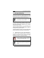
SAFETY REGULATIONS
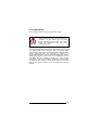
Read this manual carefully before performing any
type of connection or repair on the terminal.
NOTE
The user is responsible for any damages caused
by incorrect use of the equipment or by
inobservance of the indication supplied in this
manual.
GENERAL SAFETY RULES
Use only the components supplied by the manufacturer for the
specific F734-E series terminal being used. The use of cradles
other than those supplied with the terminal or indicated in the list in
the appendix could cause serious damage to the terminal.
Do not attempt to disassemble the F734-E series terminal, as it
does not contain parts that can be repaired by the user. Any
tampering will invalidate the warranty.
When replacing the batteries or at the end of the operative life of
the terminal, disposal must be performed in compliance with the
laws in force.
Do not submerge the terminal in liquid products.
vi
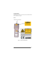
LASER SAFETY
The laser light is visible to the human eye and is emitted from the
window indicated in the figure.
F734-E
Laser beam output window
AVOID EXPOSURE
LASER LIGHT
IS EMITTED FROM
THIS APERTURE
250
This product complies with
21 CFR Subchapter J
LASER LIGHT
DO NOT STARE INTO BEAM
CLASS 2 LASER PRODUCT
MAX. OUTPUT RADIATION 1.0 mW
EMITTED WAVE LENGTH 630-680 nm
EN60825-1:2001
CAUTION – CLASS 2 LASER LIGHT
WHEN OPEN DO NOT STARE INTO BEAM
This device complies with PART 15 of the FCC Rules. Operation
is subject to the following two conditions: (1) This device may
not cause harmful interference, and (2) this device must accept
any interference received, including interference which may
cause undesired operation.
N2468
Figure 1 - F734-E Laser Safety Labels
vii
F734-E/RF
Laser beam
output window
AVOID EXPOSURE
LASER LIGHT
IS EMITTED FROM
THIS APERTURE
LASER LIGHT
DO NOT STARE INTO BEAM
CLASS 2 LASER PRODUCT
MAX. OUTPUT RADIATION 1.0 mW
EMITTED WAVE LENGTH 630 ~ 680
EN60825-1:2001
This product complies with
21 CFR Subchapter J
CAUTION – CLASS 2 LASER LIGHT
WHEN OPEN DO NOT STARE INTO BEAM
N2468
Figure 2 - F734-E/RF Laser Safety Labels
I
D
F
E
LA LUCE LASER
È VISIBILE
ALL'OCCHIO
UMANO E VIENE
EMESSA DALLA
FINESTRA
INDICATA NELLA
FIGURA.
DIE LASERSTRAHLUNG IST FÜR
DAS MENSCHLICHE
AUGE SICHTBAR UND
WIRD AM STRAHLAUSTRITTSFENTSTER
AUSGESENDET
(SIEHE BILD)
LE RAYON LASER
EST VISIBLE À
L'OEIL MU ET IL
EST ÉMIS PAR LA
FENÊTRE
DÉSIGNÉE SUR
L'ILLUSTRATION
DANS LA FIGURE
A LUZ LÁSER
ES VISIBLE AL
OJO HUMANO
Y ES EMITIDA
POR LA
VENTANA
INDICADA EN
LA FIGURA.
viii
I
D
F
E
LUCE LASER
NON FISSARE IL
FASCIO
APPARECCHIO
LASER DI
CLASSE 2
MASSIMA
POTENZA
D'USCITA:
LUNGHEZZA
D'ONDA EMESSA:
CONFORME A
EN 60825-1(2001)
LASERSTRAHLUNG
NICHT IN DEN STRAHL
BLICKEN PRODUKT
DER LASERKLASSE 2
MAXIMALE
AUSGANGSLEISTUNG:
WELLENLÄGE:
ENTSPR.
EN 60825-1(2001)
RAYON LASER
EVITER DE
REGARDER LE
RAYON APPAREIL
LASER DE
CLASSE 2
PUISSANCE DE
SORTIE:
LONGUER
D'ONDE EMISE:
CONFORME A
EN 60825-1 (2001)
RAYO LÁSER
NO MIRAR
FIJO EL RAYO
APARATO
LÁSER DE
CLASE 2
MÁXIMA
POTENCIA DE
SALIDA:
LONGITUD DE
ONDA
EMITIDA:
CONFORME A
EN 60825-1
(2001)
ENGLISH
The following information is provided to comply with the rules
imposed by international authorities and refers to the correct use of
your terminal.
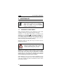
STANDARD LASER SAFETY REGULATIONS
This product conforms to the applicable requirements of both
CDRH 21 CFR 1040 and EN 60825-1 at the date of manufacture.
For installation, use and maintenance, it is not necessary to open
the device.
CAUTION
Use of controls or adjustments or performance
of procedures other than those specified herein
may result in exposure to hazardous visible
laser light.
The product utilizes a low-power laser diode. Although staring
directly at the laser beam momentarily causes no known biological
damage, avoid staring at the beam as one would with any very
strong light source, such as the sun. Avoid that the laser beam hits
the eye of an observer, even through reflective surfaces such as
mirrors, etc.
ix
ITALIANO
Le seguenti informazioni vengono fornite dietro direttive delle
autorità internazionali e si riferiscono all’uso corretto del terminale.
NORMATIVE STANDARD PER LA SICUREZZA LASER
Questo prodotto risulta conforme alle normative vigenti sulla
sicurezza laser alla data di produzione: CDRH 21 CFR 1040 e EN
60825-1.
Non si rende mai necessario aprire l’appa-recchio per motivi di
installazione, utilizzo o manutenzione.
ATTENZIONE
L'utilizzo di procedure o regolazioni differenti
da quelle descritte nella documentazione
può provocare un'esposizione pericolosa a
luce laser visibile.
Il prodotto utilizza un diodo laser a bassa potenza. Sebbene non
siano noti danni riportati dall’occhio umano in seguito ad una
esposizione di breve durata, evitare di fissare il raggio laser così
come si eviterebbe qualsiasi altra sorgente di luminosità intensa,
ad esempio il sole. Evitare inoltre di dirigere il raggio laser negli
occhi di un osservatore, anche attraverso superfici riflettenti come
gli specchi.
DEUTSCH
Die folgenden Informationen stimmen mit den Sicherheitshinweisen
überein, die von internationalen Behörden auferlegt wurden, und
sie beziehen sich auf den korrekten Gebrauch vom Terminal.
NORM FÜR DIE LASERSICHERHEIT
Dies Produkt entspricht am Tag der Herstellung den gültigen EN
60825-1 und CDRH 21 CFR 1040 Normen für die Lasersicherheit.
Es ist nicht notwendig, das Gerät wegen Betrieb oder Installations-,
und Wartungs-arbeiten zu öffnen.
ACHTUNG
Jegliche Änderungen am Gerät sowie
Vorgehensweisen,
die
nicht
in
dieser
Betriebsanleitung beschreiben werden, können
ein gefährliches Laserlicht verursachen.
Das Produkt benutzt eine Laserdiode. Obwohl zur Zeit keine
Augenschäden von kurzen Einstrahlungen bekannt sind, sollten Sie
es vermeiden für längere Zeit in den Laserstrahl zu schauen,
genauso wenig wie in starke Lichtquellen (z.B. die Sonne).
Vermeiden Sie es, den Laserstrahl weder gegen die Augen eines
Beobachters, noch gegen reflektierende Oberflächen zu richten.
x
FRANÇAIS
Les informations suivantes sont fournies selon les règles fixées par
les autorités internationales et se refèrent à une correcte utilisation
du terminal.
NORMES DE SECURITE LASER
Ce produit est conforme aux normes de sécurité laser en vigueur à
sa date de fabrication: CDRH 21 CFR 1040 et EN 60825-1.
Il n’est pas nécessaire d’ouvrir l’appareil pour l’installation,
l’utilisation ou l’entretien.
ATTENTION
L'utilisation de procédures ou réglages
différents de ceux donnés ici peut entrainer
une dangereuse exposition à lumière laser
visible.
Le produit utilise une diode laser. Aucun dommage aux yeux
humains n’a été constaté à la suite d’une exposition au rayon laser.
Eviter de regarder fixement le rayon, comme toute autre source
lumineuse intense telle que le soleil. Eviter aussi de diriger le rayon
vers les yeux d’un observateur, même à travers des surfaces
réfléchissantes (miroirs, par example).
ESPAÑOL
Las informaciones siguientes son presentadas en conformidad con
las disposiciones de las autoridades internacionales y se refieren al
uso correcto del terminal.
NORMATIVAS ESTÁNDAR PARA LA SEGURIDAD LÁSER
Este aparato resulta conforme a las normativas vigentes de
seguridad láser a la fecha de producción: CDRH 21 CFR 1040 y
EN 60825-1.
No es necesario abrir el aparato para la instalación, la utilización o
la manutención.
ATENCIÓN
La utilización de procedimientos o regulaciones
diferentes de aquellas describidas en la
documentación puede causar una exposición
peligrosa a la luz láser visible.
El aparato utiliza un diodo láser a baja potencia. No son notorios
daños a los ojos humanos a consecuencia de una exposición de
corta duración. Eviten de mirar fijo el rayo láser así como evitarían
cualquiera otra fuente de luminosidad intensa, por ejemplo el sol.
Además, eviten de dirigir el rayo láser hacia los ojos de un
observador, también a través de superficies reflectantes como los
espejos.
xi
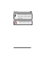
RADIO COMPLIANCE
Information for the User
ENGLISH
Contact the competent authority responsible for the management of
radio frequency devices of your country to verify the eventual
necessity of a user license. Refer to the web site
for
further
http://europa.eu.int/comm/enterprise/rtte/spectr.htm
information.
ITALIANO
Prendi contatto con l'autorità competente per la gestione degli
apparati a radio frequenza del tuo paese, per verificarne l'eventuale
necessità della licenza d'uso. Inoltre puoi trovare ulteriori
informazioni al sito:
http://europa.eu.int/comm/enterprise/rtte/spectr.htm.
FRANÇAIS
Contactez l'autorité compétente en la gestion des appareils à radio
fréquence de votre pays pour vérifier la nécessité du permis
d'usage. Pour tout renseignement vous pouvez vous adresser au
site web:
http://europa.eu.int/comm/enterprise/rtte/spectr.htm.
DEUTSCH
Um die Notwendigkeit der Verwendungslizenz zu prüfen, wenden
Sie sich an die Behörde, die auf der Radiofrequenzgerätsführung
Ihres Lands bewandert ist. Weitere Informationen sind verfügbar
auf dem Web Site:
http://europa.eu.int/comm/enterprise/rtte/spectr.htm.
ESPAÑOL
Contacta con la autoridad competente para la gestión de los
dispositivos de radio frecuencia de tu país, para verificar si es
necesario la licencia de uso. Además se puede encontrar mas
información en el sitio web:
http://europa.eu.int/comm/enterprise/rtte/spectr.htm.
xii
FCC COMPLIANCE
This compliance refers only to the F734-E batch model.
CAUTION
This device complies with PART 15 of the FCC
Rules. Operation is subject to the following two
conditions: (1) This device may not cause
harmful interference, and (2) this device must
accept any interference which may cause
undesired operation.
This equipment has been tested and found to comply with the limits
for a Class A digital device, pursuant to part 15 of the FCC Rules.
These limits are designed to provide reasonable protection against
harmful interference when the equipment is operated in a
commercial environment. This equipment generates, uses, and can
radiate radio frequency energy and, if not installed and used in
accordance with the instruction manual, may cause harmful
interference to radio communications. Operation of this equipment
in a residential area is likely to cause harmful interference in which
case the user will be required to correct the interference at his own
expense.
xiii
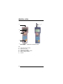
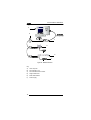
GENERAL VIEW
A
F
B
C
D
E
Figure 3 - F734-E Series Terminals Overview
Key:
A)
B)
C)
D)
E)
F)
xiv
Laser beam output window
Multi-function LED
Reset key (protected)
Cradle communications window
Battery charger contacts
Antenna
INTRODUCTION
1
1
INTRODUCTION
1.1
TERMINAL DESCRIPTION
Two different models of this terminal are provided:
Formula 734-E:
communicates with the host computer via a
cradle connection;
Formula 734-E/RF: communicates with the host computer via
radio frequency or normal cradle connection.
1.1.1
F734-E
The F734-E terminal is a lightweight, pocket-sized and fully
programmable terminal, claiming the greatest sales success of the
Datalogic PDC range.
With up to 1MB of RAM memory for managing large databases and
512KB of Flash memory for application programs of large
dimensions, F734-E solves the most complex application needs.
Furthermore, the “overspeed” capability boosts software
performance, thus increasing the operator’s productivity.
Its excellent reading performance allows barcodes to be scanned
up to a distance of 70 cm, while the long life batteries assure a
large autonomy able to cover more than one work shift. The wide
backlit LCD display, with 4 lines and 16 characters, clearly shows
much information while the practical 25-key alphanumeric keyboard
allows data, codes and descriptions to be input very quickly.
Protection against bumps, dust and water are all features that
make F734-E suitable for intensive use even in industrial
environments.
By using the optional EasyGen™ Application Generator or the DS
for Formula™ software packages for Windows environment,
developers can easily customize applications according to the end
user specific needs.
The most common data collection applications such as inventory,
picking and shipping/receiving, especially in the Retail market, are
easy to perform thanks to the F734-E features. Nevertheless, the
F734-E, thanks to the best price/performance ratio of its category,
is considered the ideal solution of many applications even in
Transportation & Logistics and Manufacturing markets.
1
F734-E SERIES TERMINALS
1
1.1.2
F734-E/RF
The F734-E/RF terminal is a lightweight, pocket-sized and fully
programmable radio frequency terminal.
It solves the most complex application needs and exploits the
"overspeed" feature to boost software performance, has 512 KB of
RAM memory for managing large databases and 512 KB of Flash
memory for application programs of large dimensions.
Software developers can easily customize applications according to
the specific needs of the end user by using the DS for Formula™
software package and integrating F734-E/RF within the new
Datalogic STAR-System™, the RF narrow band solution for mobile
applications. Barcode reading capabilities are the best you can
desire due to the high performance and high visibility laser engine,
while the long life batteries assure large autonomy, able to cover
more than one work shift.
A
F
B
C
D
E
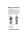
Figure 4 - F734-E series terminals overview
Key:
A)
B)
C)
D)
G)
H)
2
Laser beam output window
Multi-function LED
Reset key (protected)
Cradle communications window
Battery charger contacts
Antenna
INTRODUCTION
1
The F734-E series terminals have a backlit LCD graphic display of
16 characters by 4 lines plus a line in the upper part of the display
for the programmable icons:
The icons which can
be controlled by the
application program
The battery
charge status
Time
F734-E SERIES
TERMINALS
DATALOGIC S.P.A.
4 LINES 16 CHARS
Figure 5 - Terminal Display
1.2
APPLICATION DEVELOPMENT PROGRAMS
By using the optional EasyGen™ Application Generator or the DS
for Formula™ software package, developers can easily customize
applications according to the end user specific needs, solving the
most common data collection applications such as inventory,
picking and shipping/receiving.
EasyGen™ is the ideal solution for making Formula 734-E batch
terminals productive instantly. In a familiar environment, developers
have all the instruments at their disposal to reduce programming
times (and therefore costs) while maintaining a high standard of
quality in the creation of personalized applications whatever their
nature, whether simple (e.g. a program for inserting
codes/quantities) or more sophisticated.
The EasyGen™ package includes Systools™ 2001, the efficient
software utility to transfer data to standard ASCII files, and OLE for
Formula, the software module ActiveX - OLE Custom Control or
OCX - allowing users to easily integrate their data into applications
such as Visual Basic, Excel, Access, Delphi, etc (see par. 1.2 or
par. 1.3 for details).
DS for Formula™ is a software package that provides instruments
for fully exploiting F734-E and F734-E/RF terminals by creating
fully-structured and personalized applications (see par. 1.2 for
details).
3
1
F734-E SERIES TERMINALS
DS for Formula™ uses a «C» standard ANSI compiler, integrated
with special libraries, operating in an MS-DOS environment and
developed specifically for the type of terminal processor. The
libraries, developed by Datalogic, permit direct management of the
terminal functions. For example, the management of barcode
reading devices is immediate and rational thanks to interaction with
functions that automatically start up the barcode acquisition
procedure.
Equally transparent, by using a philosophy of events programming,
is the procedure managing the keyboard, display, serial and radiofrequency communication, calendar/clock and, either directly or
through a vdisk function, the data memory organized into banks.
DS for Formula™ also offers a series of effective general purpose
application examples which represent an excellent starting point
while simultaneously providing a practical guide for studying and
working on complex or personalized programs. Refer to the "Tools"
paragraph in the DS for Formula™ Manual for details.
1.3
DOWNLOADING EASYGEN™ DEMO
By logging on to www.datalogic.com/services/support and clicking
on the Products>Portable Data Collection Terminals link, you can
download for free the EasyGen™ Demo Software package
containing the following items:
•
EasyGen™ Demo Version (user-friendly and highly productive
application generator)
•
SysTools™2001 (efficient utility for data exchange with the
terminal)
•
OLE for Formula (useful ActiveX software module for easy
integration of Windows applications)
•
The most common application examples (data collection,
inventory, goods picking, assisted sales) available in 5
languages (English, French, German, Italian, Spanish)
•
The complete documentation in PDF format.
4
INTRODUCTION
1.4
1
PACKAGE CONTENTS
The F734-E terminal package includes:
−
n. 1 F734-E terminal complete with batteries;
−
n. 1 user's manual
−
n. 1 test chart
The F734-E/RF terminal package includes:
−
n. 1 F734-E/RF terminal complete with batteries;
−
n. 1 user's manual
−
n. 1 test chart
Remove all components from their packing and
check that they are in good condition and that
they correspond to the shipment documents.
CAUTION
NOTE
1.5
Keep the packing and boxes in case it is
necessary to send the terminal back for
technical assistance. Damage caused by
improper packing is not covered by the warranty
Rechargeable battery packs are not initially
charged. Therefore the first operation to perform
is to charge them in the appropriate cradle (see
par. 2.2.1 and par. 4.1).
ACCESSORIES
F951/C
Charger
F951 – F951 Dark
Transceiver/Charger - RS232/RS485
F951/V
Vehicle Transceiver/Charger RS232/RS485 (without power
supply)
F950/4/C
Charger - 4 slots
F950/4
Transceiver/Charger - 4 slots - RS232 (x1) / RS485 (x4)
F950/4/RS232
Transceiver/Charger - 4 slots - RS232 with NCK for RS485
F902
T-Box
5
1
F734-E SERIES TERMINALS
NCK
RS485 Network/PC connection kit
FBK73X-E
Battery Kit NiMh F734-E
FBS73X-E
Battery Kit NiMh F734-E (5 pcs pack)
FCB232 D 25 F
RS232 serial connection cable PC/XT T 8 M - D25 F 2 m
FCB232 D 9 F
RS232 serial connection cable for PC/AT T 8 M - D9 F 2 m
FCB485 SYS
RS485 serial connection cable for SYSNET 2 m
FCB EAV
Eavesdrop cable kit 2+2 m
Rubber Cover
Rubber protection cover F732-E/F734-E Batch
Functional Case – order number 94ACC1266
Belt Holster – order number 94ACC1268
F734-E Holster with swivel
DS for Formula™
Development system for Formula Basic Line
CA51
Compiler 8051 Compiler kit V7 for F6XX and F7XX
EasyGen™
Easy application generator package for Formula batch
terminals: F660-E, F725-E, F732-E, F734-E
Utility Tools Full Pack Adv. Ed. F734-E
Software package for Windows 95, 98, NT
ForWin™
Software package for developing RF terminal applications
STARGATE™
Radio base station allowing data transmission in wireless
network
STAR Modem™
Radio modem providing wireless RF communication
STAR-Box™
Connection box
6
CONNECTIONS
2
2.1
2
CONNECTIONS
CRADLE
To make the F734-E series terminal operative, it is necessary to
insert it into the Formula 951 Transceiver Charger cradle or into the
Formula 950/4 Multi Transceiver Charger which has been
previously connected to the power supply and to a host computer
with an available RS232, RS485 or Eavesdrop line.
The following figure describes the F951 cradle:
B
A
C
D
E
Figure 6 - F951 Cradle Overview
Key:
A)
Red/Green LED:
Green = terminal not inserted or charge level being maintained
Red = charge in progress
B)
Cradle on/off switch
C)
RJ connector for RS485 and Eavesdrop connection
D)
Power jack (9 V)
E)
RJ connector for RS232 and RS485 host connection
The use of cradles other than those expressly
specified may damage the terminal.
CAUTION
7
F734-E SERIES TERMINALS
2
2.2
CONNECTION TO THE HOST COMPUTER
Before proceeding with this phase, make sure
that both the computer and the terminal are
switched off.
CAUTION
2.2.1
RS232 Connection
To connect the F951 cradle to the host computer, proceed as
indicated below:
1- Connect the cable to the serial port of the host computer.
2- Connect the other end of the same cable (RJ connector) to the
RS232 port of the cradle (point E in the previous figure).
3- Insert the power-supply plug into the jack on the base of the
cradle (point D in the previous figure).
4- Attach the power supply to a power outlet.
5- Turn on the cradle (point B in the previous figure) and the
computer.
6- Put the F734-E terminal into the cradle and, if necessary, wait
for battery recharging.
A
B
C
D
Figure 7 - RS232 Single Cradle Connection
Key:
A) Host computer
B) Serial cable
C) Single cradle F951
D) Power supply
8
CONNECTIONS
2
A
B
C
D
Figure 8 - RS232 Multi Cradle Connection
Key:
A)
Host computer
B)
Serial cable
C)
Multi-cradle F950/4
D)
Power supply
NOTE
The RS232 connection allows transmission
between the host computer and the first station of
the multi-cradle. For this reason, it is necessary
to insert an RS232/RS485 converter between the
host and the cradle to enable transmission with
all the four stations.
9
F734-E SERIES TERMINALS
2
2.2.2
Connection with Eavesdrop Interface
The cable Kit 94A054030 provides two cables; one for Eavesdrop
connections and one for Modem connections.
The Eavesdrop connection enables the F734-E terminal to be
connected to an existing asynchronous RS232 line (for example
between the host computer and video terminal).
The modem connection enables the terminal to be connected to a
host system using a modem.
B
A
C
D
E
Figure 9 - Eavesdrop and Modem Connection
Key:
A)
Video terminal
B)
Host computer
C)
Cradle F951
D)
Power supply
E)
Modem
10
CONNECTIONS
2.2.3
2
RS485 Connection
The RS485 line allows connecting several terminals to a single
RS232 line by means of a network (see the "Formula 904/N User
Manual).
If the network is made using the Formula 902 T-Box, the line can
be extended up to 1200 meters and up to 32 different types of
Formula cradles can be connected. If multiple cradles are used, the
individual work stations must be counted.
The RS485 connection is the only one allowing
all the stations of a multi-cradle to be available for
transmission/reception from the host computer.
NOTE
11
F734-E SERIES TERMINALS
2
A
B
C
D
E
F
Figure 10 - RS485 Connection
Key:
A)
Host computer
B)
Formula 902 T-box
C)
Formula 904/N Interconverter
D)
Single cradle F951
E)
Multi cradle F950/4
F)
Power supply
12
CONNECTIONS
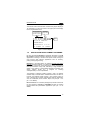
2.2.4
2
RF Connection
The RF connection allows the F734-E/RF terminal to communicate
with the host via radio frequency using the STARGATE™ RF base
station connected to the host computer.
C
A
B
D
Figure 11 - RF Connection
Key:
A)
Host computer
B)
Power supply
C)
F734-E/RF terminal
D)
STARGATE™ RF base station
13
F734-E SERIES TERMINALS
2
2.3
CONNECTION CABLE
Several types of cables are provided depending on the computer
and on the connection.
The following cables and cable Kits are listed with their order
number.
RS232 Connection with PC/AT or compatible: cable
94A054000
Host/PC side
9-pin D-sub
(female)
Cradle side
RJ45
TX
1
2
RTS
2
8
GND
3
5
CTS
4
7
RX
5
3
4
1
Figure 12 - RS232 Cable Pinout
Modem and/or
94A054030
Eavesdrop
Connection:
cable
Kit
The beige cable allowing the Eavesdrop connection has the
following pinout::
Eavesdrop Cable
DTE side
25-pin D-sub
(male)
Cradle side
RJ45
TX
1
3
RX
2
2
GND
3
7
4
5
8
20
Figure 13 - Eavesdrop Cable Pinout
14
TO TERMINAL
CONNECTIONS
CONNECTIONS
2
The black flat cable allowing the Modem connection has the
following pinout:
Modem Cable
DB25 side
25-pin D-sub
(male)
Cradle side
RJ45
TX
1
2
RTS
2
4
CTS
4
5
RX
3
5
GND
3
TO MODEM
CONNECTIONS
7
8
20
Figure 14 - Modem Cable Pinout
RS485 Connection: cable 94A054020
Twisted Pair
RJ
RJ
RX/TX
7
7
RX/TX
6
6
GND
3
3
Figure 15 - RS485 Cable Pinout
15
F734-E SERIES TERMINALS
3
3
USE AND OPERATION
The F734-E and F734-E/RF are lightweight, pocket-sized and fully
programmable terminals with 512 KB (512/1024 KB for F734-E
model) of RAM memory to manage large databases and 512 KB of
Flash memory for application programs of large dimensions.
It is necessary to load an application program
onto the terminal to exploit its features.
NOTE
By using the optional EasyGen™ Application Generator or the DS
for Formula™ software package, developers can easily customize
applications according to the end user specific needs, solving the
most common data collection applications such as inventory,
picking and shipping/receiving.
The Demo Version of EasyGen™ can be downloaded free of
charge from the Datalogic web site together with 5 ready-to-use
example applications in 5 different languages. Refer to chapter 6 of
the EasyGen™ User's Manual for details.
The following descriptions assume the terminal is loaded with an
EasyGen™ application. If however, a custom application is loaded
then refer to the specific documentation for terminal operation.
3.1
DESCRIPTION OF KEYS USING EASYGEN™
It is possible to assign customized functions to function keys
depending on the application program developed. The functions
described below refer to a terminal using an application program
developed with the EasyGen™ Application Generator.
Refer to chapter 6 "EasyGen™ Interpreter
Program" of the EasyGen™ User's Manual for
more details about the key functions.
CAUTION
Every time a key is pressed, the F734-E series
terminal remains turned on for a maximum of 20
seconds.
NOTE
16
USE AND OPERATION
3
ARROW KEYS: only available for the
application when not in “Select or Data
Edit” mode.
SCAN KEY: activates the laser for barcode
scanning and turns on the terminal when it
is off.
FUNCTION KEYS: keys <F1>, <F2>, <F3>
and <F4> are available for the loaded
application. Function F5 activates the
“Select” mode and only in this mode you
can use F6, F7 and F8 functions:
<SHIFT> followed by <F1> = F5
“Select” mode
<SHIFT> followed by <F2> = F6
Data search
<SHIFT> followed by <F3> = F7
Deletion
<SHIFT> followed by <F4> = F8
Data display
ESC KEY: used in the “Data display” mode.
SHIFT KEY: Enables the entry of
alphabetical characters (written in white on
the keyboard) when followed by the
pressing of a numeric key: for example if
you want to enter the alphabetical character
“A”, you have to press <SHIFT>+<7>.
The number of times the SHIFT key is
pressed determines the choice of
alphabetical character: for example if you
want to enter the alphabetical character
“N”,
you
have
to
press
<SHIFT>+<SHIFT>+<5>, if you want to
enter the alphabetical character “X”, you
have to press
<SHIFT>+<SHIFT>+<SHIFT>+<2> and so
on.
The fourth time the SHIFT key is pressed,
the SHIFT function is disabled. The SHIFT
function can also be disabled by waiting for
a time-out of 2 seconds after being
pressed.
17
3
F734-E SERIES TERMINALS
By pressing the <SHIFT> key followed by
the <RIGHT ARROW> key, the graphic
display’s contrast increases to the allowed
maximum, and then returns to 0 value.
NUMERIC KEYS: allow the entry and
display of the main numeric symbol. If the
<SHIFT> has first been pressed, the choice
of alternative alphabetic characters will be
activated.
BACKSPACE KEY:
character entered.
deletes
the
last
SPACE KEY: allows the introduction of a
blank space. If the <SHIFT> has been
pressed previously, the choice of
alternative characters will be activated.
ENTER KEY: allows validation of what has
been typed.
PROTECTED
RESET
BUTTON: it is activated
by inserting a blunt object
in
the
slot
while
simultaneously pressing
the <SCAN> key.
18
USE AND OPERATION
3.2
3
BARCODE SCANNING
When reading a barcode point the terminal laser beam at the code
from an appropriate distance and simultaneously press the
<SCAN> key. The beam emitted by the laser must completely
cover the barcode; the LED (and the acoustic signal, if activated)
will indicate if the scan was carried out correctly.
NO
NO
OK
OK
Figure 16 - F734-E Series Terminal Scanning a Barcode
NOTE
Throughout the operation of the application, the
, and the time icon will always be
battery icon
activated, the latter in accordance with the setting
of the terminal internal clock.
In addition, when an acoustic signal is emitted,
will appear.
the loudspeaker icon
19
F734-E SERIES TERMINALS
3
3.3
DELETING THE APPLICATION PROGRAM
This procedure allows deleting application programs developed with
DS for Formula™. If you want to delete programs provided or
developed by EasyGen™, refer to chapter 6 of the EasyGen™
manual.
The following procedure causes data to be
deleted even if not completed.
NOTE
If the application program must be cancelled follow the instructions
below:
1-
Press the <SCAN> key and the protected reset button at the
same time; the display will show:
PROGRAM
ERASE?
= No
Yes =
If you do not want to delete the application
program, press the {▲} or wait about 25 seconds.
NOTE
2-
To continue with the deletion, press the ▼ key; after a few
seconds, the display will show:
BOOTSTRAPLOADER v6r1
ErasPrgFlash
3-
20
Once the deletion procedure is completed, the terminal is
ready to receive a new application program. This is installed
using the methods described in the DS for Formula™ manual.
USE AND OPERATION
3.4
3
DOWNLOADING DATA TO HOST
Data can be downloaded from the terminal to the host PC in
different ways, depending on the application loaded and on the
terminal model.
If working with F734-E (batch model), the application software
allows downloading data onto the PC by simply inserting the
terminal into the cradle or by direct operator intervention on the
terminal or host computer.
Figure 17 - Downloading Data with F734-E
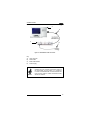
If working with F734-E/RF, the application software will allow
downloading data by radio frequency transmission between the
terminal and a STARGATE™ RF base station.
Figure 18 - Downloading Data with F734-E/RF
21
F734-E SERIES TERMINALS
4
4
MAINTENANCE
NOTE
4.1
Rechargeable battery packs (NiCd/NiMh) are not
initially charged. Therefore the first operation to
perform is to charge them in the appropriate
cradle. See chapter 2 and the following
paragraph "Charging the Batteries".
CHARGING THE BATTERIES
Battery charge life depends on many variables but, under normal
conditions, autonomy is more than enough for a day work.
Information on the battery-charge status is provided by the
. The information provided by the
dedicated icon on the display
icon is valid only when the terminal is not inserted in the cradle.
Four different charge levels are given from a maximum value (all
the icon segments full) to a minimum one which warns of pre-lowbattery (icon empty and intermittently flashing).
Recharging should be made after using the terminal until the
batteries are nearly flat.
When the terminal display window shows the
message "BATTERY LOW", wait until it is
turned off before inserting it in the cradle.
CAUTION
Recharge the terminal by simply inserting it into its cradle;
Datalogic S.p.A. recommends a minimum uninterrupted recharging
time of eight hours. When using the NiMh battery a standard
recharge does not allow taking fully advantage of the improved
battery technology. For this reason, a recharging time of about 60
hours is advised to get the NiMh maximum capacity.
When batteries are new, or have not been recharged for a long
time, it is necessary to perform two or three charge and discharge
cycles (with complete use) before the batteries are able to reach
their maximum capacity.
22
MAINTENANCE
NOTE
4
During the battery recharge the color of the LED
positioned on the cradle changes from red to
green. If using the NiCd battery pack, the LED
color changes when 70-80% of the complete
charge is reached. If using the NiMh battery
pack, the LED color changes when 50-60% of the
complete charge is reached due to the battery
increased capacity.
If the terminal remains inactive for a
prolonged period such as two weeks, it is
advisable to download all the stored data
onto a computer and extract the battery pack.
CAUTION
23
F734-E SERIES TERMINALS
4
4.2
REPLACING THE BATTERIES
Before proceeding, ensure that the terminal is
switched off and that the data it contains has
been downloaded onto the host computer.
CAUTION
To replace the batteries correctly, proceed as follows.
1-
Turn over the terminal and
remove the two battery
cover screws.
2-
Lift the battery cover as
shown in the figure and
extract the old battery pack.
1
2
24
MAINTENANCE
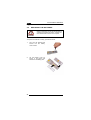
3-
4
Replace the battery
pack, making sure the
batteries are inserted
in the right direction
as indicated within the
case.
-+
-
+
Before inserting the battery pack into the
terminal, ensure the battery polarity matches
with the one indicated within the case.
CAUTION
CONTACTS
Figure 19
CAUTION
4-
Figure 20
When inserting the battery pack, first slide it
towards the springs compressing them until
the contacts at the other end are cleared (see
Figure 18). Then, push downwards to insert
the pack (see Figure 19). Be very careful not
to damage the contacts when pushing
downwards.
Close the battery cover and tighten the screws
Dispose of used batteries in accordance with the
relevant laws in force.
NOTE
25
4
4.3
F734-E SERIES TERMINALS
CLEANING THE TERMINAL
Clean the terminal from time to time with a slightly damp cloth.
Do not use alcohol, corrosive products or solvents.
26
TROUBLESHOOTING
5
5
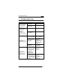
TROUBLESHOOTING
PROBLEM
CAUSE
REMEDY
When the <SCAN>
button is pressed
the terminal does
not come on.
Flat batteries.
Recharge terminal.
Batteries completely
flat or broken.
Replace batteries.
Flat batteries.
Recharge terminal.
Batteries completely
flat or broken.
Replace batteries.
There is no power
supply to the cradle.
Connect the power
supply and switch
on the cradle.
The serial cable is
not correctly
connected.
Check the
connection to the
cradle and the
serial port of the
computer.
The terminal already
contains an
application program.
Follow instructions
to cancel the
application.
When the <SCAN>
button is pressed,
the terminal
displays the
message
BATTERY LOW
and switches itself
off.
The terminal does
not load the
application program.
The terminal
displays an error
message FAULT
CODE.P21CO4.
The application
Load the correct
loaded is not suitable application
for the terminal in
program.
use. The terminal
displays the
message FAULT
CODE P21CO4.
Other faults. The
terminal displays an
error message other
than FAULT CODE
P21 CO4.
Contact your
Datalogic
representative for
technical
assistance.
27
F734-E SERIES TERMINALS
6
6
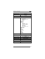
TECHNICAL FEATURES
F734-E
Optical Features
Light source
Scan rate
Minimum resolution
Skew angle
Pitch angle
Depth of field
Electrical Features
Micro-controller
Program memory
Data RAM
EEPROM
Calendar/clock
Power supply
Battery charger
Physical Features
Technology
Dimensions (LxWxH)
Weight
Buzzer
LED
Display
Keyboard
Environmental Features
Working temperature
Storage temperature
Relative humidity
Degree of protection
28
F734-E/RF
Laser-scanner; VLD source; 630-680nm
35±5 scans/sec
0.15 mm / 6 mils
± 65°
± 65°
30 to 700 mm / 1.2 to 27.6 in
(depends on the density of the code)
8-bit CMOS
8 KB bootstrap-loader PROM
512 KB Flash-memory
512/1024 KB
512 KB SRAM
SRAM
256 bytes
Quartz RT, programmable date and
time with automatic handling of leap
years.
4 NiCd 250mA/h
4 NiMh 650 mA/h
batteries
batteries
Formula 951 or Formula 950/4
SMT (Surface Mount Technology)
165x56x34 mm
209x56x37 mm
6.5x2.2x1.3 mil
8.2x2.2x1.5 in
(with antenna)
200 g / 7.05 oz
215 g / 7.6 oz
(with battery)
(with battery)
Piezoelectric, programmable in
frequency and duration
Programmable red/green LED
High contrast, back-lit LCD graphic
display with 97 x 32 matrix
25 silicone rubber keys, reset button
0 °C to +50 °C (32 °F to +122 °F)
-20 °C to +70 °C (-4 °F to +158 °F)
95% without condensation
Protected from rain and dust
TECHNICAL FEATURES
Environmental Features
Electrostatic charges
Drop resistance
Laser safety
6
IEC 801-2
IEC 68-2-32 up to 1 m (39 in) onto
concrete
EN 60825-1 class 2 laser product
Programming Features
Barcodes decoded
Standard 3/9
Extended 3/9
Italian pharmaceutical
Interleaved 2/5
ITF 14
Industrial 2/5
Matrix 2/5
UPC - EAN
UPC only
UPC/EAN + Addon 2
UPC/EAN + Addon 5
UPC-E only
UPC 8 only
UPC-A & EAN 13 only
Codabar (NW7)
Monarch (2/7)
PAKO
Code 128
EAN 128
Delta A IBM
MSI
Code 93
Zellweger
Storagetek
Operating modes
bootstrap loader; application program
Transmission Features
F951 - F950/4 interface
Cradle-Host interface
Transmission speed
Transmission protocol
Transmission modes
Parity
via optical transceiver with serial
protocol
RS232; RS485; Eavesdrop
300 to 19200 bits/sec
Program-definable
RS232 full-duplex; RS485 half-duplex
mark, space, odd, even
F734-E/RF Transmission Features
Frequency
Power emitted
433.92 MHz
10 mW Max
29
GLOSSARY
Barcode
A pattern of variable-width bars and spaces which represents
numeric or alphanumeric data in binary form. The general format of
a barcode symbol consists of a leading margin, start character,
data or message character, check character (if any), stop
character, and trailing margin. Within this framework, each
recognizable symbology uses its own unique format.
Baud Rate
A measure for data transmission speed.
Bit
Binary digit. One bit is the basic unit of binary information.
Generally, eight consecutive bits compose one byte of data. The
pattern of 0 and 1 values within the byte determines its meaning.
Bits per Second (bps)
Number of bits transmitted or received per second.
Byte
On an addressable boundary, eight adjacent binary digits (0 and 1)
combined in a pattern to represent a specific character or numeric
value. Bits are numbered from the right, 0 through 7, with bit 0 the
low-order bit. One byte in memory can be used to store one ASCII
character.
Decode
To recognize a barcode symbology (e.g., Codabar, Code 128,
Code 3 of 9, UPC/EAN, etc.) and analyze the content of the
barcode scanned.
EEPROM
Electrically Erasable Programmable Read-Only Memory. An onboard non-volatile memory chip. Data is maintained when power is
not present.
FLASH
It is a type of non-volatile memory that can be erased and
reprogrammed in units of memory called blocks. It is a variation of
EEPROM memory which, unlike flash memory, is erased and
rewritten at the byte level, and therefore is slower than flash
memory updating. Data is maintained when power is not present.
30
Host
A computer that serves other terminals in a network, providing
services such as network control, database access, special
programs, supervisory programs, or programming languages.
Liquid Crystal Display (LCD)
A display that uses liquid crystal sealed between two glass plates.
The crystals are excited by precise electrical charges, causing
them to reflect light outside according to their bias. They use little
electricity and react relatively quickly. They require external light to
reflect their information to the user.
Light Emitting Diode (LED)
A low power electronic light source commonly used as an indicator
light. It uses less power than an incandescent light bulb but more
than a Liquid Crystal Display (LCD).
RAM
Random Access Memory. Data in RAM can be accessed in random
order, and quickly written and read. This memory is volatile and
therefore data is lost when power is not present.
RTC
Real Time Clock.
Terminal
A Datalogic portable computer product.
31
INDEX
A
Accessories; 15
Application Development
Programs; 13
Cleaning the Terminal; 36
Replacing the Batteries;
34
P
Package Contents; 15
B
Barcode Scanning; 29
R
Reference Documentation; 1
C
Connections; 17
Connection Cable; 24
Connection with
Eavesdrop Interface; 20
Cradle; 17
RF Connection; 23
RS232 Connection; 18
RS485 Connection; 21
D
Deleting the Application
Program; 30
Downloading Data to Host;
31
Downloading EasyGen™
Demo; 14
G
General View; 10
M
Maintenance; 32
Charging the Batteries; 32
32
S
Safety Regulations; 2
FCC Compliance; 9
Laser Safety; 3
Radio Compliance; 8
T
Technical Features; 38
Electrical; 38
Environmental; 38
Optical; 38
Physical; 38
Programming; 39
RF Transmission; 39
Transmission; 39
troubleshooting; 37
U
Use and Operation; 26
DATALOGIC S.p.A.,
Via Candini, 2
40012 - Lippo di Calderara
Bologna - Italy
dichiara che
declares that the
déclare que le
bescheinigt, daß das Gerät
declare que el
F734-X, Pocket Terminal
F951, Single Transceiver/Charger
F950/4, Multi Transceiver/Charger
e tutti i suoi modelli
and all its models
et tous ses modèles
und seine modelle
y todos sus modelos
sono conformi alle Direttive del Consiglio Europeo sottoelencate:
are in conformity with the requirements of the European Council Directives listed below:
sont conformes aux spécifications des Directives de l'Union Européenne ci-dessous:
den nachstehenden angeführten Direktiven des Europäischen Rats:
cumple con los requisitos de las Directivas del Consejo Europeo, según la lista siguiente:
89/336/EEC EMC Directive e 92/31/EEC, 93/68/EEC
and
et
und
y
emendamenti successivi
further amendments
ses successifs amendements
späteren Abänderungen
succesivas enmiendas
Basate sulle legislazioni degli Stati membri in relazione alla compatibilità elettromagnetica
ed alla sicurezza dei prodotti.
On the approximation of the laws of Member States relating to electromagnetic
compatibility and product safety.
Basées sur la législation des Etates membres relative à la compatibilité
électromagnétique et à la sécurité des produits.
Über die Annäherung der Gesetze der Mitgliedsstaaten in bezug auf elektromagnetische
Verträglichkeit und Produktsicherheit entsprechen.
Basado en la aproximación de las leyes de los Países Miembros respecto a la
compatibilidad electromagnética y las Medidas de seguridad relativas al producto.
Questa dichiarazione è basata sulla conformità dei prodotti alle norme seguenti:
This declaration is based upon compliance of the products to the following standards:
Cette déclaration repose sur la conformité des produits aux normes suivantes:
Diese Erklärung basiert darauf, daß das Produkt den folgenden Normen entspricht:
Esta declaración se basa en el cumplimiento de los productos con las siguientes normas:
EN 55022, August 1994:
LIMITS AND METHODS OF MEASUREMENTS OF RADIO
DISTURBANCE CHARACTERISTICS OF INFORMATION
TECHNOLOGY EQUIPMENT (ITE)
EN 55024, September 1998:
INFORMATION TECHNOLOGY EQUIPMENT, IMMUNITY
CHARACTERISTICS. LIMITS AND METHODS OF
MEASUREMENTS.
Lippo di Calderara, 25/06/2001
Ruggero Cacioppo
Quality Assurance Supervisor
DATALOGIC S.p.A.,
Via Candini, 2
40012 - Lippo di Calderara
Bologna - Italy
dichiara che
declares that the
déclare que le
bescheinigt, daß das Gerät
declare que el
F734-E/RF 512 K, Pocket Terminal
e tutti i suoi modelli
and all its models
et tous ses modèles
und seine modelle
y todos sus modelos
sono conformi alla Direttiva del Consiglio Europeo sottoelencata:
are in conformity with the requirements of the European Council Directive listed below:
sont conformes aux spécifications de la Directive de l'Union Européenne ci-dessous:
der nachstehenden angeführten Direktive des Europäischen Rats:
cumple con los requisitos de la Directiva del Consejo Europeo, según la lista siguiente:
1999/5/EEC R&TTE
Questa dichiarazione è basata sulla conformità dei prodotti alle norme seguenti:
This declaration is based upon compliance of the products to the following standards:
Cette déclaration repose sur la conformité des produits aux normes suivantes:
Diese Erklärung basiert darauf, daß das Produkt den folgenden Normen entspricht:
Esta declaración se basa en el cumplimiento de los productos con las siguientes normas:
EN 60950-1, December 2001:
INFORMATION TECHNOLOGY EQUIPMENT – SAFETY
PART 1: GENERAL REQUIREMENTS
ETSI EN 301 489-03, November 2001: ELECTROMAGNETIC
COMPATIBILTY AND RADIO
SPECTRUM MATTERS (ERM); ELECTROMAGNETIC
COMPATIBILITY (EMC) STANDARD FOR RADIO
EQUIPMENT AND SERVICES; PART 3: SPECIFIC
CONDITIONS FOR SHORT-RANGE DEVICES (SRD)
OPERATING ON FREQUENCIES BETWEEN 9 KHZ AND
40 GHZ
ETSI EN 300 220-3, September 2000: ELECTROMAGNETIC
COMPATIBILTY AND RADIO
(ERM); SHORT-RANGE
SPECTRUM
MATTERS
DEVICES (SRD); RADIO EQUIPMENT TO BE USED IN
THE 25 MHZ TO 1000 MHZ FREQUENCY RANGE
WITH POWER LEVELS RANGING UP TO 500 MW;
PART 3: HARMONISED EN COVERING ESSENTIAL
REQUIREMENTS UNDER ARTICLE 3.2 OF THE R&TTE
DIRECTIVE.
Lippo di Calderara, 26/08/2003
Ruggero Cacioppo
Quality Assurance Laboratory Manager