1
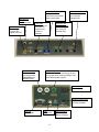
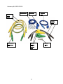
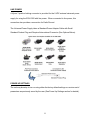
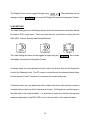
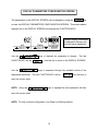
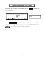
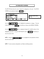
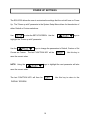
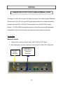
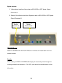
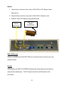
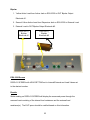
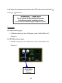
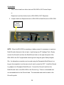
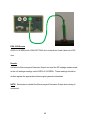
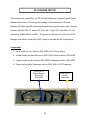
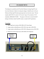
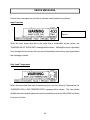
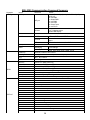
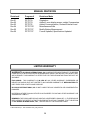
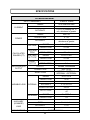
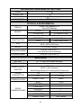
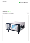
ELECTROSURGICAL
UNIT ANALYZER
ESU-2300
USER MANUAL
BC BIOMEDICAL
ESU-2300
TABLE OF CONTENTS
WARNINGS, CAUTIONS, NOTICES ............................................................................ ii
DESCRIPTION .............................................................................................................
1
LAYOUT .......................................................................................................................
3
OPERATION ................................................................................................................
6
SCREENS ...................................................................................................................... 9
POWER UP SETTINGS .............................................................................................. 16
TESTING...................................................................................................................... 18
ERROR MESSAGES ................................................................................................... 34
COMMUNICATION PROTOCOL ................................................................................. 37
COMMUNICATION COMMAND SUMMARY ............................................................... 38
MANUAL REVISIONS .................................................................................................. 39
LIMITED WARRANTY ................................................................................................. 39
SPECIFICATIONS ....................................................................................................... 40
NOTES ......................................................................................................................... 42
i
WARNING - USERS
The ESU-2300 is for use by
skilled technical personnel only.
WARNING - USE
The ESU-2300 is intended for testing only and
should never be used in diagnostics, treatment
or any other capacity where it could come in
contact with a patient.
WARNING - MODIFICATIONS
The ESU-2300 is intended for use within the
published specifications. Any application
beyond these specifications or any unauthorized
user modifications may result in hazards or
improper operation.
WARNING - CONNECTIONS
All connections to patients must be removed
before connecting the DUT to the ESU-2300. A
serious hazard may occur if the patient is
connected when testing with the ESU-2300.
Do not connect any leads from the patient
directly to the ESU-2300 or DUT.
WARNING - TEST LEADS
There are retractable ends on the test leads for
use with the DUT to avoid possible electric
shock, skin burns or personal injury. Do not
touch any metal on the banana plugs or probes.
WARNING - POWER SUPPLY
Unplug the Power Supply before
cleaning the surface of the Analyzer.
ii
CAUTION - LIQUIDS
Do not submerge or spill liquids on the
ESU-2300.
CAUTION - SERVICE
The ESU-2300 is intended to be serviced only by
authorized service personnel. Troubleshooting
and service procedures should only be
performed by qualified technical personnel.
CAUTION - ENVIRONMENT
Exposure to environmental conditions outside
the specifications can adversely affect the
performance of the ESU-2300. Allow ESU-2300 to
acclimate to specified conditions for at least 30
minutes before attempting to operate it.
CAUTION - VENTILATION
The ESU-2300 includes ventilation slots to
prevent overheating during operation. These
slots and internal fan should not be blocked.
CAUTION - CLEANING
Do not immerse. The ESU-2300 should be
cleaned by wiping gently with a damp, lint-free
cloth.
A mild detergent can be used if desired.
CAUTION - INSPECTION
The ESU-2300 should be inspected before each
use for wear and should be serviced if any parts
are in question.
iii
NOTICE – CE
The ESU-2300 Analyzers bear the
mark
Based on the following testing standards:
ELECTROMAGNETIC COMPATIBILITY DIRECTIVE
EMC – Directive 89/336/EEC and 2004/108/EC as amended by
92/31/EEC, 93/68/EEC and Directive 91/263/EEC [ TTE/SES ]
EN 61326-1:1997 + A1:1998 + A2:2001 + A3:2003
“Electrical equipment for measurement, control and
laboratory use – EMC requirements”
This equipment has been type tested by an independent, accredited testing laboratory
and compliance was demonstrated to the above standard to the extent applicable.
EMISSIONS
Radiated and Line Conducted Emissions
EN 61000-3-2
EN 61000-3-3
Harmonic Current Emissions
Voltage Fluctuation and Flicker
IMMUNITY– CLASS C
EN 61000-4-2
EN 61000-4-3
EN 61000-4-4
EN 61000-4-5
EN 61000-4-6
EN 61000-4-11
Electrostatic Discharge
Radiated Electric Field Immunity
Electrical Fast Transients / Bursts
Surge Voltage
Conducted Disturbance
Voltage Dips and Short Interrupts
LOW VOLTAGE DIRECTIVE
EC – Directive 73/23/EC
EN 61010-1:2001
“Safety requirements for electrical equipment for measurement, control, and
laboratory use – General requirements”
This equipment has been type tested and compliance was demonstrated
to the above standard to the extent applicable.
iv
NOTICE – SYMBOLS
Symbol
Description
Caution
(Consult Manual for Further Information)
RF Current Transformer
Per European Council Directive
2002/95/EC, do not dispose of this
product as unsorted municipal waste.
NOTICE – ABBREVIATIONS
A
A/D
C
CF
°
Ampere(s)
Analog to Digital
Celsius
Crest Factor
degree(s)
DUT
Device Under Test
DFA
Digital Fast Acquisition
ESU
Electrosurgical Unit
Ext
External
Int
Internal
kg
kilogram(s)
kHz
kilohertz
MHz
Megahertz
µA
microampere(s)
mA
milliampere(s)
mm
millimeter(s)
ms
millisecond(s)
mV
millivolt(s)
#
Number
Ω
Ohm(s)
Pk
Peak
Pk-Pk
Peak to Peak
PC
Personal Computer
Lbs
pounds
RF
Radio Frequency
RH
Relative Humidity
RMS
Root Mean Square
sec
second(s)
USA
United States of America
VDC
Volts Direct Current
W
Watt(s)
v
NOTICE – DISCLAIMER
BC GROUP INTERNATIONAL, INC. WILL NOT BE RESPONSIBLE
FOR ANY INJURIES SUSTAINED DUE TO UNAUTHORIZED
EQUIPMENT MODIFICATIONS OR APPLICATION OF EQUIPMENT
OUTSIDE OF THE PUBLISHED INTENDED USE AND
SPECIFICATIONS.
NOTICE – DISCLAIMER
BC GROUP INTERNATIONAL, INC. RESERVES THE RIGHT TO
MAKE CHANGES TO ITS PRODUCTS OR SPECIFICATIONS AT
ANY TIME, WITHOUT NOTICE, IN ORDER TO IMPROVE THE
DESIGN OR PERFORMANCE AND TO SUPPLY THE BEST
POSSIBLE PRODUCT. THE INFORMATION IN THIS MANUAL HAS
BEEN CAREFULLY CHECKED AND IS BELIEVED TO BE
ACCURATE. HOWEVER, NO RESPONSIBILITY IS ASSUMED FOR
INACCURACIES.
NOTICE – CONTACT INFORMATION
BC BIOMEDICAL
BC GROUP INTERNATIONAL, INC.
3081 ELM POINT INDUSTRIAL DRIVE
ST. CHARLES, MO 63301
USA
1-800-242-8428
1-314-638-3800
www.bcgroupintl.com
[email protected]
ESU-2300 User Manual
www.bcgroupintl.com
08/12
Copyright © 2012
Made in the USA
Rev 06
vi
BC BIOMEDICAL
ESU-2300
ELECTROSURGICAL UNIT ANALYZER
The Model ESU-2300 is a highly accurate Electrosurgical Analyzer containing an internal
precision load bank. We have designed the ESU-2300 to comply with electrosurgical
manufacturer industry-standard current sensing technology. A highly accurate RF Current
Transformer is used to convert the high frequency RF signal from the ESU generator to a
voltage signal. This technique results in a much more accurate and frequencyindependent measurement. Our DFATM (Digital Fast Acquisition) technology then digitizes
the Current Transformer ouput signal using a high-speed analog to digital converter. This
technology allows the ESU-2300 to directly measure complex electrosurgical waveforms,
and provides highly accurate and stable results not requiring interpretation. The ESU-2300
is intended to be routinely used to measure the various parameters relating to the testing
and performance validation of electrosurgical generators.
The following are highlights of some of the main features:
TRUE RMS READINGS USING PATENT PENDING DFATM TECHNOLOGY
INDUSTRY STANDARD CURRENT SENSING TECHNOLOGY
mA, mV, mV PEAK, CREST FACTOR AND POWER (WATTAGE) RANGES
INTERNAL PRECISION LOAD RESISTOR NETWORK: 50 TO
750 OHMS IN 50 INCREMENTS
EXTERNAL LOAD RESISTOR CAPABILITY – ALLOWS THE USE OF
EXTERNAL RESISTORS EITHER AS AN INDEPENDENT LOAD OR IN
CONJUNCTION WITH THE INTERNAL LOAD.
INTERNAL LOAD RESISTOR NETWORK IS COOLED WITH
TEMPERATURE AND POWER CONTROLLED COOLING FAN
USES AN INTERNAL 0.1:1 RATIO PRECISION RF CURRENT
TRANSFORMER
INDEPENDENT CQM (REM/ARM) RESISTOR NETWORK: 1 TO 500
IN 1 INCREMENTS
RF LEAKAGE MEASUREMENTS THROUGH 200 AUXILIARY TEST
LOAD
INTERNAL RECHARGEABLE BATTERY ALLOWS OPERATION
INDEPENDENT OF LINE POWER
LARGE GRAPHICS DISPLAY WITH CURSOR SELECTION
OF OPTIONS AND SETUP OF PARAMETERS
DIGITAL CALIBRATION – NO POTS TO TURN
SELECTABLE DISPLAY OPTIONS
TACTILE KEYS WITH AUDIO FEEDBACK
1
STANDARD ACCESSORIES:
BC20 – 00125
BC20 – 21105
BC20 – 41352
BC20 – 41341
BC20 – 205XX
ACCESSORY KIT (TEST LEADS)
UNIVERSAL POWER SUPPLY
COMMUNICATIONS CABLE (USB)
COMMUNICATIONS CABLE (RS232)
STANDARD POWER ADAPTER
(International Options, see Page 8 for details)
OPTIONAL ACCESSORIES:
BC20 – 00232
BNC TO BNC CABLE
VISHAY-DALE NH-250 PRECISION 1% TOLERANCE NON-INDUCTIVE LOAD
RESISTORS:
BC20-00200
BC20-00201
BC20-00202
BC20-00203
BC20-00204
BC20-00205
BC20-00206
BC20-00207
BC20-00208
BC20-00209
BC20-00210
BC20-00211
BC20-00212
BC20-00213
BC20-00240
5 , 250 WATT RESISTOR
10 , 250-WATT RESISTOR
20 , 250-WATT RESISTOR
30 , 250-WATT RESISTOR
50 , 250-WATT RESISTOR
100 , 250-WATT RESISTOR
200 , 250-WATT RESISTOR
300 , 250-WATT RESISTOR
500 , 250-WATT RESISTOR
1000 , 250-WATT RESISTOR
2000 , 250-WATT RESISTOR
3000 , 250-WATT RESISTOR
4000 , 250-WATT RESISTOR
5000 250-WATT RESISTOR
POWER RESISTOR BANANA JACK ADAPTER(2 PER SET)
2
LAYOUT
This section looks at the layout of the ESU-2300 and gives descriptions of the elements
that are present.
Large LCD
Graphical
Display with
High Intensity
Backlight
Ventilation Slots
(Both Sides)
for efficient load
resistor cooling
Back Light Key
for turning on
and off the
backlight
Carrying
Handle
3
5 Light Touch Keys
for Dynamic
functions:
These keys are
labeled in the
bottom portion of
the screen and
change function
based on operating
mode.
Oscilloscope
Output
BNC connector
Active Input
Banana Jack
input for RF
signal from DUT
Dispersive Inputs
Banana Jacks for
connection to generator
patient return path
Loop Input
Banana Jack for
use when an
external load
resistor is
attached
CQM Test Inputs
Banana Jacks for
use during CQM
(REM/ARM) and
RECQM Tests
Aux Test Load Jacks
Banana Jacks for
use during RF
leakage tests
Earth/Ground
Reference Jacks
Banana Jacks for
use during RF
leakage tests
Earth/Ground Input
Banana Jack for use connecting the unit
to a ground when running Leakage Tests
while utilizing battery power
Power On/Off
Rocker Switch
External Power Input
Kycon 3 position
locking receptacle
RS-232
Comm Port
USB
Comm Port
4
LED Indicators
Line Power
Battery Charging
Accessory Kit, BC20-00125:
RECQM Lead
(Pin)
CQM Lead
(No Pin)
Dispersive
Lead
Active
Leads
Jumper
Leads
Earth/Gound
Lead
Banana
Jack
Alligator
Clips
5
Ground
Lug
OPERATION
GENERAL OPERATION
The ESU-2300 is controlled by 5 light touch keys for navigation, plus 1 light touch key for
LCD display backlight control. The navigation keys allow the user to move around within
the displayed parameters, select the desired options, choose a specific category and
control the setup for the unit. When a key is depressed there is an audio click when it is
accepted, or a “Razz” tone if the key is invalid.
A large LCD graphics display with high intensity white backlight provides the user with
information about the current status of the device configuration options, test results and
more. The display identifies the function of each key on a dynamic basis. As the operation
mode changes, the key functions change to suit the operating mode.
BACKLIGHT KEY
The Graphic LCD display may be viewed with or without the backlight. Depressing any key
will activate the backlight. However, since the backlight will drain the internal rechargeable
battery at an accelerated rate if left on, it will automatically be shut off after a user
programmable delay when running the ESU-2300 on battery power.
The
key is provided to toggle the backlight on or off at any time.
NOTE: The backlight parameter in the System Setup screen may be set to Off, 1-20 sec
or Always On.
6
FUNCTION KEYS
There are five
keys that are used to provide general operational control. The
functions of the keys vary depending on the current screen. The section of the screen
just above the key indicates its current meaning.
NOTE: Only functions that are available to the user will be visible at any given time.
Sample Function Key Labeling
SERIAL COMMUNICATIONS
There are two serial ports on the side panel. One is a standard USB port and the other is a
DB-9 RS-232 port. Both ports can be used to connect to a PC to get measurements and
remotely configure the ESU-2300. The RS-232 port is also used to update the ESU-2300
firmware. For more details on remote operation see the Communication Protocol section
on page 53.
OSCILLOSCOPE OUTPUT
A BNC connector is provided to connect an oscilloscope to the unit. This output is an
uncalibrated attenuated version of the ESU Generator output waveform.
POWER SWITCH
The main power switch for the Analyzer is located on the side panel.
7
LINE POWER
A Kycon 3 position locking connector is provided for the 9 VDC external universal power
supply for using the ESU-2300 with line power. When connected to line power, this
connection also provides a connection for Earth/Ground.
The Universal Power Supply takes a Standard Power Adapter Cable with Small
Standard Product Plug and Required International Connector (See Options Below).
POWER UP SETTINGS
The unit may be setup to turn on using either the factory default settings or a custom set of
parameters as previously saved by the user (See Power Up Settings section for details).
8
SCREENS
DISPLAY SCREEN
When the ESU-2300 is first powered up, the DISPLAY SCREEN will be shown. This
screen contains one, two or five parameter DISPLAY ZONES, the LOAD SETTING and the
available FUNCTION KEYS. Each Display Zone can be customized to show the desired
RF measurement parameters of RMS Current (mA), RMS Voltage (mV), RMS Power
(Watts), Peak Voltage (mV pk), Peak to Peak Voltage (mV Pk-Pk) or Crest Factor (CF).
The Load Mode Setting can be set to show the desired Internal, External and
Internal/External loads. The Load Selection can be set to change the internal, external, or
internal plus external load resistances.
DISPLAY ZONES:
Sample Display Screen with
one Display Zone
Sample Display Screen with
two Display Zones
Sample Display Screen with
five Display Zones
9
The Display Zones can be toggled through using
changed using the
. The parameters can be
key to enter the Display Parameters Configuration Screen.
LOAD SETTING
The Load Setting portion of the Display Screen shows the load selection and value that will
be used for ESU output tests. There are three load set up choices for testing with the
ESU-2300: Internal, External and Internal/External.
The Load Setting and value can be toggled through using the
key to enter
the Display Parameters Configuration Screen.
In Internal mode, the user applies the Active Lead to the Active Jack and the Dispersive
Lead to the Dispersive Jack. The RF current is routed through the selected internal loads
and the internal Current Transformer to measure the current and power.
In External mode, the user applies the Active Lead to the Active Jack and then connects
another lead from the Loop Jack to the external load(s). The Dispersive Lead then goes to
the other side of the external load(s). It is important to make sure that the external load
resistance parameter in the ESU-2300 is set to the real value of the external load(s).
10
In Internal/External mode, the user applies the Active Lead to the Active Jack and then
connects another lead from the Dispersive Jack to the external load(s). The Dispersive
Lead then goes to the other side of the external load(s). It is important to make sure that
the external load resistance parameter in the ESU-2300 is set to the real value of the
external load(s).
FUNCTION KEYS
DISPLAY – This key will toggle between one parameter, two parameter or five parameter
Display Zones.
CHANGE – This key will enter the Display Parameters Configuration Screen where
parameters can be selected and changed.
HOLD – This key will freeze the current reading in the Display Zone.
RECQM – This key will enter the RECQM Test Screen.
SETUP – This key will enter the System Setup Screen.
11
DISPLAY PARAMETERS CONFIGURATION SCREEN
The parameters on the DISPLAY SCREEN can be changed by using the
key
to enter the DISPLAY PARAMETERS CONFIGURATION SCREEN. This screen adds a
highlight line to the DISPLAY SCREEN and changes the FUNCTION KEYS.
Sample Display Parameters
Configuration Screen with
the load value highlighted
Use the
FUNCTION KEY will be
Use the
keys to highlight the parameter to change.
The last
. Use this key to return to the DISPLAY SCREEN.
keys to sequence through the available values of the
highlighted parameter. The last FUNCTION KEY will be
. Use this key to
save the current value.
NOTE: Using the
keys to highlight the next parameter will also
save the current value.
NOTE: To save a custom configuration, see Power Up Settings section.
12
CQM/RECQM (REM/ARM) TEST SCREEN
The RECQM TEST SCREEN
can be entered using the
key from the
DISPLAY SCREEN.
Sample RECQM Test
Screen
Use the
keys to change the value of the resistance setting. This
setting ranges from 1
to 500
in 1
increments. The last FUNCTION KEY will be
. Use this key to return to the DISPLAY SCREEN.
13
SYSTEM SETUP SCREEN
The SETUP Mode allows the user to adjust the configuration of the unit. The SETUP
SCREEN can be entered using the
key.
Sample System Setup
Screen
Use the
FUNCTION KEY will be
Use the
keys to highlight the parameter to change.
The last
. Use this key to return to the DISPLAY SCREEN.
keys to sequence through the available values of the
highlighted parameter. The last FUNCTION KEY will be
. Use this key to
save the current value.
NOTE: Using the
keys to highlight the next parameter will also
save the current value.
NOTE: To save a custom configuration, see Power Up Settings section.
14
SYSTEM SETUP
The following is a breakdown of the parameters available in the configuration of the unit
and their available options:
System Setup Configuration
Parameter
Description
Range
Backlight
Controls whether the backlight is on or off or how
long to wait for user input before automatically
turning off the backlight in battery powered mode.
Off, 0-20 sec,
Always on
(Factory Default = 10)
Battery Life
Displays remaining battery life (charge) in percent
0-100% (Read Only)
Power Source
Displays whether the unit is on battery power or
line powered
Battery or Line
(Read Only)
Power up with
Determines the power up mode of the ESU-2300.
The default mode shows a single mA parameter
display. Set this parameter to custom to display
the saved startup mode. Set this parameter to
Save current as custom to save the settings for the
next time power is cycled.
Defaults
Custom
Set Current as Custom
Num A/D Samples
Sets the number of A/D converter readings used in
each mA RMS computation. A higher setting
requires more computation and is slower, but
results in a more stable reading.
1024
2048
4096
8192
16384
32768
(Factory Default =
32768)
Display Averaging
Sets the number of mA RMS readings that are
averaged. A higher number will cause the display
to update slower, but will give a more stable
reading.
1-30 Readings
(Factory Default = 11)
Software
Displays current software program.
15
(Read Only)
POWER UP SETTINGS
The ESU-2300 allows the user to customize the settings that the unit will have on Power
Up. The “Power up with” parameter in the System Setup Menu allows for the selection of
either Default or Custom selections.
Use
to enter the SETUP SCREEN. Use the
keys to
highlight the “Power up with” parameter.
Use the
keys to change the parameters to Default, Custom or Set
Current as Custom. The last FUNCTION KEY will be
. Use this key to
save the current value.
NOTE: Using the
keys to highlight the next parameter will also
save the current value.
The last FUNCTION KEY will then be
.
DISPLAY SCREEN.
16
Use this key to return to the
Default
If this option is selected, the unit will power up to the dual display zone screen, which will:
Show the mA and Watts readings
Put the ESU-2300 into Internal Load mode
Use 300 ohms as the default internal load
Custom
If this option is selected, the unit will Power Up using the unique sets of parameters that
were last customized and saved by the user. The DISPLAY SCREEN will use the
parameters in the Display Zones that were last configured and saved by the user.
Set Current as Custom
This choice is provided to create the set of custom startup screen parameters. The user
simply configures each screen to show the desired parameters and then enters the Set
Current as Custom choice in the SETUP SCREEN. The current configuration is saved as
the Custom Power Up values and will be used when the “Power up with” parameter is set
to Custom. This configuration will remain the Custom configuration until it is written over
using the Set Current as Custom option in the “Power up with” parameter.
17
TESTING
GENERATOR OUTPUT TESTS USING INTERNAL LOADS
The purpose of this test is to verify the output accuracy of the Electrosurgical Generator
Device Under Test (DUT) at a given RF power setting, based on the selected internal
precision test load (50 to 750 Ω in 50 Ω increments) from the ESU-2300 resistor
network. The ESU-2300 should always be set to match the electrosurgical generator
manufacturer’s specified test load for the mode and output waveform selected.
Connections
Monopolar ouputs:
1. Yellow Active Lead from Active Jack on ESU-2300 to DUT Output.
2. Blue Dispersive Lead from Dispersive Jack on ESU-23-00 to DUT Dispersive.
ESU (DUT)
Active
Electrode
ESU (DUT)
Patient Return/
Dispersive
Electrode
18
Bipolar outputs:
1. Yellow Active Lead from Active Jack on ESU-2300 to DUT Bipolar Output
Electrode #1.
2. Second Yellow Active Lead from Dispersive Jack on ESU-2300 to DUT Bipolar
Output Electrode #2.
ESU (DUT)
Bipolar
Electrode #1
ESU (DUT)
Bipolar
Electrode #2
ESU-2300 Screen
DISPLAY SCREEN with LOAD SETTING set to Internal and Load Value set to the
desired number.
Results
Watts reading on DISPLAY SCREEN will display the measured power through the
currently selected load resistance. The DUT specs should be verified based on this
information.
19
GENERATOR OUTPUT TESTS WITH EXTERNAL LOADS
The purpose of this test is to verify the output accuracy of the Electrosurgical Generator
Device Under Test (DUT) at a given RF power setting, based upon an attached external
load resistor. The external load resistor attached to the ESU-2300 should always be
set to match the electrosurgical generator manufacturer’s specified test load for the
mode and output waveform selected.
Connections
Monopolar:
1. Yellow Active Lead from Active Jack on ESU-2300 to DUT Output.
3. Blue Dispersive Lead from Loop Jack on ESU-2300 to External Load.
4. External Load to DUT Dispersive.
ESU (DUT)
Active
Electrode
ESU (DUT)
Patient Return/
Dispersive
Electrode
20
Bipolar:
1. Yellow Active Lead from Active Jack on ESU-2300 to DUT Bipolar Output
Electrode #1.
2. Second Active Lead from Loop Jack on ESU-2300 to External Load.
3. External Load to DUT Bipolar Output Electrode #2.
ESU (DUT)
Bipolar
Electrode #1
ESU (DUT)
Bipolar
Electrode #2
ESU-2300 Screen
DISPLAY SCREEN with LOAD SETTING set to External and Load Value set to the
desired number.
Results
Watts reading on DISPLAY SCREEN will display the measured power through the
external load resistance(s). The DUT specs should be verified based on this
information.
21
GENERATOR OUTPUT TESTS WITH
INTERNAL / EXTERNAL TEST LOADS
The purpose of this test is to verify the output accuracy of the Electrosurgical Generator
Device Under Test (DUT) at a given RF power setting, based on the selected internal
precision test load (50 to 750 Ω in 50 Ω increments) from the ESU-2300 resistor
network, in addition to series-connected external load resistor (0 to 5200 Ω in 1 Ω
increments). The resulting test load (the ESU-2300 internal load + the external load)
should always be set to match the electrosurgical generator manufacturer’s specified
test load for the mode and output waveform selected.
Connections
Monopolar:
1. Yellow Active Lead from Active Jack on ESU-2300 DUT Output.
2. Blue Dispersive Lead from Dispersive Jack on ESU-2300 to External Load.
3. External Load to DUT Dispersive Lead
ESU (DUT)
Active
Electrode
ESU (DUT)
Patient Return/
Dispersive
Electrode
22
Bipolar:
1. Yellow Active Lead from Active Jack on ESU-2300 to DUT Bipolar Output
Electrode #1.
2. Second Yellow Active Lead from Dispersive Jack on ESU-2300 to External Load.
3. External Load to DUT Bipolar Output Electrode #2.
ESU (DUT)
Bipolar
Electrode #1
ESU (DUT)
Bipolar
Electrode #2
ESU-2300 Screen
DISPLAY SCREEN with LOAD SETTING set to Internal/External and Load Values set
to the desired number.
Results
Watts reading on DISPLAY SCREEN will display the measured power through the
summed load consisting of the internal load resistance and the external load
resistance(s). The DUT specs should be verified based on this information.
23
CQM (REM/ARM) TEST
The Return Electrode Contact Quality Monitor Test Mode allows the user to test the
CQM/RECQM (REM/ARM) safety feature available on most electrosurgical generators.
This feature exists mainly to prevent high frequency burns caused when the dispersive
electrode contact with the patient degrades to a high impedance connection, resulting
in increased current density at the electrode site. To prevent this, electrosurgical
generators typically employ a dual-sided pad, with independent electrical connections
from each side of the pad to the generator. The generator utilizes special electronic
circuitry that circulates a small current flow at a specific frequency through this circular
electrical path to monitor the contact impedance between the pad and the patient.
There are two basic types of this safety feature:
1. A basic continuity type test, where the ESU is looking for a very low resistance
(usually < 20 ohms) between the two dispersive pads
2. A more advanced RECQM test where the generator usually tests for a
resistance between the two dispersive pads to be greater than 5 ohms and less
than 135 ohms, as well as testing whether the measured resistance has changed
by a certain percentage over the initial measured resistance.
The usual way to test these two safety features of the electrosurgical generators is to
use a separate decade box and go through the ranges, checking when the generator
alarms out. However, the ESU-2300 includes a digitally adjustable resistor, separate
from the internal test load resistor network, giving the user the ability to do all testing
with one device.
24
In this feature, the resistance across the two white CQM Jacks can be varied from 0
to 500
in 1
increments.
WARNING – CQM TEST
Do not connect the Electrosurgical Generator
Active Electrode while conducting this test.
Do not enable the Electrosurgical Output at any time.
Connections
For CQM (continuity type):
1. CQM Lead (without pin) from CQM Jacks on side of ESU-2300 to DUT
Dispersive.
For RECQM (resistance type):
1. RECQM Lead (with pin) from CQM Jacks on side of ESU-2300 to DUT
Dispersive
ESU (DUT)
Patient Return/
Dispersive
Electrode
25
ESU-2300 Screen
RECQM SCREEN with OHMS SETTING set to the desired value.
Results
The DUT should be checked for appropriate alarms in both safety modes (CQM and
RECQM).
NOTICE – MANUFACTURER’S SPECS
The user must consult the manufacturer’s
manual for each DUT to determine the correct
test procedures and alarm specifications
to follow.
26
RF LEAKAGE TEST #1
This leakage test, specified by the IEC as Active (or Dispersive) Electrode to Ground, is
for testing the RF leakage to Earth/ Ground of an Isolated Output type CF
electrosurgical generator from a single active or dispersive lead. The test complies with
IEC 601.2.2, section 19.101b, figure 104 and section 19.102, adopted by ANSI/AAMI
HF18-2001. The purpose of this test is to verify that open circuit RF leakage of the
Device Under Test (DUT) meets or exceeds the IEC specification.
NOTE: DO NOT TEST AN EARTH REFERENCED TYPE BF ELECTROSURGICAL
GENERATOR WITH THIS TEST, THE RESULTING MEASUREMENT WILL BE
ERRONEOUS.
WARNING – ONE LEAD AT A TIME
Only test one lead of the ESU Generator at a time
27
Connections
1. Either Active Lead from Active Jack on ESU-2300 to DUT Active Output.
or
Dispersive Lead from Active Jack on ESU-2300 to DUT Dispersive
2. Jumper Lead from Dispersive Jack on ESU-2300 to Earth/Ground on ESU-2300.
ESU (DUT)
Active
Electrode
NOTE: When the ESU-2300 is operating on battery power it is necessary to supply an
Earth/Ground reference to the unit prior to performing any RF Leakage Tests. Simply
connect the Ground Lead from the Earth/Ground Jack on the right side panel of the
ESU-2300 to the DUT equipotential chassis ground using the green Safety Alligator
Clip. An alternative connection can be made using the Receptacle Earth/Ground, as
long as the receptacle is on the same circuit used to power the DUT. Install the Ground
Lug adaptor into Receptacle Earth/Ground. Connect the Ground Lead from the
Earth/Ground Jack on the ESU-2300 to the Ground Lug. There is a retractable and
non-retractable end on the Ground Lead. The retractable end must be used on the
Ground Lug side.
28
ESU-2300 Screen
DISPLAY SCREEN with LOAD SETTING set to Internal and Load Value set to 200
ohm.
Results
Activate the Electrosurgical Generator Output and read the RF leakage measurement
as the mA leakage readings on the DISPLAY SCREEN. These readings should be
verified against the appropriate electrosurgical generator standards.
NOTE: Remember to disable the Electrosurgical Generator Output when testing is
completed.
29
RF LEAKAGE TEST #2
This leakage test, specified by the IEC as Earth Reference Leakage Type BF (Load
Between Electrodes), is for testing the leakage to Earth/Ground of a Ground
Referenced Output type BF electrosurgical generator from the active output. This test
complies with IEC 601.2.2, section 19.101a, test 1, figure 102, and section 19.102,
adopted by ANSI/AAMI HF18-2001. The purpose of this test is to verify that the RF
leakage of the Device Under Test (DUT) meets or exceeds the IEC specification.
Connections
1. Active Lead from Aux Jack on ESU-2300 to DUT Active Output.
2. Jumper Lead from Earth/Ground on ESU-2300 to Active Jack on ESU-2300.
3. Jumper Lead from Aux Jack on ESU-2300 to Dispersive Jack on ESU-2300.
4. Dispersive Lead from Dispersive Jack on ESU-2300 to DUT Dispersive.
ESU (DUT)
Patient Return/
Dispersive
Electrode
30
ESU (DUT)
Active
Electrode
ESU-2300 Screen
DISPLAY SCREEN with LOAD SETTING set to Internal and Load Value set to 200
ohm.
Results
Activate the Electrosurgical Generator Output and read the RF leakage measurement
as the mA leakage readings on the DISPLAY SCREEN. These readings should be
verified against the appropriate electrosurgical generator standards.
NOTE: Remember to disable the Electrosurgical Generator Output when testing is
completed.
NOTE: When the ESU-2300 is operating on battery power it is necessary to supply an
Earth/Ground reference to the unit prior to performing any RF Leakage Tests. Refer to
page 29 for connection details.
31
RF LEAKAGE TEST #3
This leakage test, specified by the IEC as Earth Reference Leakage Type BF (Load
from Active Electrode to Earth) is for testing the leakage to Earth/Ground of a Ground
Referenced Output type BF electrosurgical generator from the active output. This test
complies with IEC 601.2.2, section 19.101a, test 2, figure 102, and section 19.102,
adopted by ANSI/AAMI HF18-2001.
The purpose of this test is to verify that the RF
leakage of the Device Under Test (DUT) meets or exceeds the IEC specification.
Connections
1. Active Lead from Aux Jack on ESU-2300 to DUT Active Output.
2. Jumper Lead from Earth/Ground on ESU-2300 to Aux Jack on ESU-2300.
3. Jumper Lead from Earth/Ground on ESU-2300 to Dispersive Jack on ESU-2300.
4. Dispersive Lead from Active Jack on ESU-2300 to DUT Dispersive.
ESU (DUT)
Patient Return/
Dispersive
Electrode
ESU (DUT)
Active
Electrode
32
ESU-2300 Screen
DISPLAY SCREEN with LOAD SETTING set to Internal and Load Value set to 200
ohm.
Results
Activate the Electrosurgical Generator Output and read the RF leakage measurement
as the mA leakage readings on the DISPLAY SCREEN. These readings should be
verified against the appropriate electrosurgical generator standards.
NOTE: Remember to disable the Electrosurgical Generator Output when testing is
completed.
NOTE: When the ESU-2300 is operating on battery power it is necessary to supply an
Earth/Ground reference to the unit prior to performing any RF Leakage Tests. Refer to
page 29 for connection details.
33
ERROR MESSAGES
Several error messages are provided to indicate invalid operating conditions.
Input Overload
Sample Input Overload
Screen
When the input signal rises above the range that is measurable by the system, the
“WARNING INPUT OVERLOAD” message will be shown. Although the input is protected
from damage at these levels, the user should immediately remove any input signal when
this message is shown.
High Load Temperature
When the measured load bank temperature goes over the Warning Temperature the
“WARNING HIGH LOAD TEMPERATURE” message will be shown. The user should
disable the electrosurgical generator output immediately and let the ESU-2300 cool down
for a period of time.
34
Fan Blocked
Sample Fan Blocked
Screen
If there is a mechanical problem with the internal fan, such as a locked bearing or some
physical item blocking the path of the fan blades, the “WARNING FAN BLOCKED”
message will be shown. The user should check the unit for any obvious protrusions. The
user should not use the unit for any electrosurgical generator testing and should return the
ESU-2300 to the factory for immediate servicing.
WARNING – FAN BLOCKED WARNING
Do not activate the electrosurgical generator to the
internal loads of the ESU-2300, as there will be no
way for the internal loads to cool down.
Disable Electrosurgery Generator Output Before Changing Load
Sample Disable Output
Screen
If the user tries to change load resistances while the ESU-2300 detects RF power
applied, the “CAUTION DISABLE ESU OUTPUT BEFORE CHANGING LOAD”
message will be displayed.
35
Low Battery Lockout
This message will be shown when the battery voltage is too low for proper operation.
When this message is displayed, the keys are locked out. Line power should be
applied as soon as possible to recharge the system battery.
36
COMMUNICATION PROTOCOL
The communication protocol provides a means to completely configure and use the
ESU-2300 from a PC. All of the functions available through the front panel can be
performed through the communication ports. All of the measurements made by the
ESU-2300 are accessible as well. This provides for hands free or automated operation
of the ESU-2300.
Command Syntax
The command description is broken into 3 columns; the KEYWORD, the PARAMETER
FORM and COMMENTS.
Keyword
The KEYWORD column provides the name of the command. The actual name of the
command consists of one or more keywords since SCPI commands are based on a
hierarchical structure, also known as a tree system.
In such a system, associated commands are grouped together under a common node in
the hierarchy, analogous to the way leaves at a same level are connected at a common
branch. This and similar branches are connected to fewer and thicker branches, until they
meet at the root of the tree. The closer to the root, the higher a node is considered in the
hierarchy. To activate a particular command, the full path to it must be specified.
The highest level node of a command is called the Keyword, followed by the Node,
Subnode, and then the value.
Not all commands require the complexity of the full command path. For example, the
Status? command doesn’t have a Node or Subnode.
Some commands allow for reading and writing data and some commands are Read Only.
To indicate a read function, a question mark (?) is placed at the end of the command path.
For example, a write command to change the internal load resistance to 100 ohms would
be “CONFigure:LOAD:INTernal 100<cr>”, where <cr> indicates a carriage-return. For
example, a mArms read command would be “READ:MArms?<cr>”, which would return a
value of “xxx.x<cr><lf>” where <cr> is a carriage-return and <lf> is a linefeed.
Lowercase letters indicate the long-form of the command (for example,
CONFigure:INPut:RANGe?) and can be omitted for simplification. Uppercase letters
indicate the abbreviated, or short-form, of the commands and must be included (for
example, CONF:INP:RANG?).
All commands sent to the unit are terminated with a Carriage Return.
NOTE: Commands can be entered in either upper or lowercase or a mixture of the two,
uppercase and lowercase. Commands sent to the ESU-2300 are not case sensitive.
37
ESU-2300 Communication Command Summary
Keywords
CONFigure
Nodes
DISPlay
Subnodes
Values
x is the Screen # (1-3) and y is the Zone # (1-5).
nn=0 to 5:
0= mA RMS
1= Watts RMS
2= mV RMS
3= mV Peak
4= Crest Factor
5= mV Pk-Pk
Range: 1-4
1-3 = # display zones
4=RECQM Display
SxZy nn
SCReen
HOLD
ON,OFF
LOAD
MODE
INTernal, EXTernal, INT/EXTernal
Internal load resistance, 50-750 ohms in 50 ohm
steps
INTernal
EXTernal
RECqm
0-500 ohms
INPut
AVERaging
External load resistance, 0 to 5200 ohms
1-30 readings
NUMsamples
SYSTem
READ
STATus?
POWerup
1024, 2048, 4096, 8192, 16384, 32768
DEFaults, CUStom, SETCurrent
BACKlight
0-21 (special cases: 0 = always off, 21=always on)
KEY
BKLT, KEY1-KEY5
VERsion?
[read only]
MVrms?
MArms?
WArms?
MVPeak?
MVPP?
CF?
FANspeed?
TEMPerature?
Bit Value
0
1
1
2
2
4
3
8
4
16
5
32
6
64
7
128
8
256
9
512
10 1024
11 2048
12 4096
13 8192
14 16384
15 32768
Returns: mV RMS [read only]
Returns: mA RMS [read only]
Returns: Watts RMS [read only]
Returns: mV Peak [read only]
Returns: mV Peak to Peak [read only]
Returns: CF [read only]
Returns: Fanspeed [read only]
Returns: Current Load Bank Temperature [read only]
Definition
Hold Mode
Calibration Mode
Low Battery
Fan Blocked Rotor
Load Bank Overtemp
Error Present
mV Out of Range
mA Out of Range
Watts Out of Range
mV Peak Out of Range
Crest Factor Out of Range
mV Peak to Peak Out of Range
38
MANUAL REVISIONS
Revision #
Program #
Revisions Made
Rev 01
Rev 02
Rev 03
Rev 04
Rev 05
Rev 06
DT7377A
DT7377D
DT7377E
DT7377CE
DT7377CF
DT7377CF
Origination
Added 5 zone display screen, added 3 parameters
Added Communications, Revised External Load
Miscellaneous Edits
Modify Battery Measurement
Format Updated, Specifications Updated
LIMITED WARRANTY
WARRANTY: BC GROUP INTERNATIONAL, INC. WARRANTS ITS NEW PRODUCTS TO BE FREE
FROM DEFECTS IN MATERIALS AND WORKMANSHIP UNDER THE SERVICE FOR WHICH THEY
ARE INTENDED. THIS WARRANTY IS EFFECTIVE FOR TWELVE MONTHS FROM THE DATE OF
SHIPMENT.
EXCLUSIONS: THIS WARRANTY IS IN LIEU OF ANY OTHER WARRANTY EXPRESSED OR
IMPLIED, INCLUDING, BUT NOT LIMITED TO ANY IMPLIED WARRANTY OF MERCHANTABILITY
OR FITNESS FOR A PARTICULAR PURPOSE.
BC GROUP INTERNATIONAL, INC. IS NOT LIABLE FOR ANY INCIDENTAL OR CONSEQUENTIAL
DAMAGES.
NO PERSON OTHER THAN AN OFFICER IS AUTHORIZED TO GIVE ANY OTHER WARRANTY OR
ASSUME ANY LIABILITY.
REMEDIES: THE PURCHASER'S SOLE AND EXCLUSIVE REMEDY SHALL BE: (1) THE REPAIR OR
REPLACEMENT OF DEFECTIVE PARTS OR PRODUCTS, WITHOUT CHARGE. (2) AT THE OPTION
OF BC GROUP INTERNATIONAL, INC., THE REFUND OF THE PURCHASE PRICE.
P:/Manuals/BCGroup/…/ESU-2000/ESU-2300_UM_Rev06.doc
39
SPECIFICATIONS
RF MEASUREMENT
CURRENT
INPUT FREQUENCY
RANGE
RESOLUTION
ACCURACY
POWER
RANGE
RESOLUTION
CALCULATED
RANGES (CT)
OSCILLOSCOPE
OUTPUT
VARIABLE LOAD
AUXILLARY
(LEAKAGE)
LOAD
CONNECTIONS
VOLTAGE
PEAK
VOLTAGE
PK-TO-PK
± 2.5% of Reading or± 15
mA, whichever is greater
RANGE
RESOLUTION
RANGE
RESOLUTION
400.0 W
0.1 W
± 4% of Reading or ± 3 W,
whichever is greater
2.0 to 700.0 mV
0.1 mV
1000.0 mV
0.1 mV
RANGE
0.0 to 1.0 mV
ACCURACY
VOLTAGE
10 kHz to 10 MHz
20 to 2500 mA RMS
1 mA RMS
RESOLUTION
RANGE
CREST
FACTOR
RESOLUTION
OUTPUT
CONNECTION
0.1 mV
1.4 to 500
0.1
Isolated, Uncalibrated
BNC (50 Ω)
INTERNAL, EXTERNAL,
SELECTIONS
INTERNAL + EXTERNAL
RANGE
50 to 750 Ω
RESOLUTION
50 Ω
TYPE
Non-Inductive
INTERNAL
ACCURACY
± 1% ± 0.5 Ω
POWER RATING
225 W
10 seconds on, 30 seconds
DUTY CYCLE
off
RANGE
0 to 5200 Ω
EXTERNAL
RESOLUTION
1Ω
VALUE
200 Ω
TYPE
Non-Inductive
ACCURACY
± 1%
POWER RATING
225 W
4 mm SAFETY BANANA
40
RETURN ELECTRODE MONITOR TEST LOAD
RANGE
0 to 500
RESOLUTION
1
ACCURACY
CONNECTIONS
± 2% FS or ± 2 , whichever is greater
4 mm SAFETY BANANA
PHYSICAL & ENVIRONMENTAL
DISPLAY
MEMORY
240x64 Pixel Graphical LCD,
White LED Backlight
SETUP
EEPROM, All Parameters
RETENTION
10 Years w/o Power
FAN
CONSTRUCTION
SIZE
WEIGHT
OPERATING RANGE
STORAGE RANGE
120 mm Internal Fan
ENCLOSURE
Kydex Plastic
FACE
Lexan, Back Printed
6.30 x 13.50 x 13.40 inches
160.0 x 342.9 x 340.4 mm
≤ 17.5 Lbs (7.95 kg)
15 to 30 °C (59 to 86 °F)
20 to 80% RH, Non-Condensing
-20 to 60 °C (-4 to 140 °F)
ELECTRICAL
BATTERY
6V, 7.2 Amp-Hour Sealed Lead Acid
BATTERY CHARGER
Internal 2-state Independent charger with float mode
POWER SUPPLY
ADAPTER
9 VDC, 5 A
BC20-21105 (Universal)
See Ordering Section for Country-specific Power cord
POWER
CONSUMPTION
USB
COMMUNICATIONS
RS-232
COMMUNICATIONS
ON
<3A
OFF
< 250 μA
CONNECTIONS
USB-B
BAUD
DATA BITS
115200
8
START BITS
STOP BITS
PARITY
HANDSHAKING
CONNECTIONS
1
1
None
None
DB-9 Female
41
NOTES
42
43
BC GROUP INTERNATIONAL, INC.
3081 ELM POINT INDUSTRIAL DRIVE
ST. CHARLES, MO 63301
USA
1-800-242-8428
1-314-638-3800
www.bcgroupintl.com
[email protected]
ESU-2300 User Manual
08/12 – Rev 06
Copyright © 2012
Made in the USA