1
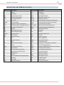
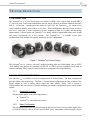
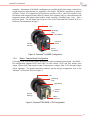
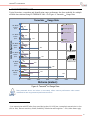
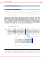
Tamarisk®320
17 μm 320x240 Long Wave Infrared Camera
User Manual
Document No: 1012593
Revision: D
©Copyright 2012, DRS TECHNOLOGIES, Inc. - All rights reserved.
13532 N. Central Expressway
Dallas, TX 75243
877.377.4783
www.drsinfrared.com
All rights reserved. The contents of this document may not be reproduced in whole or in parts
without the written consent of the copyright owner.
NOTICE
ALL STATEMENTS, INFORMATION, AND RECOMMENDATIONS IN THIS MANUAL ARE BELIEVED
TO BE ACCURATE BUT ARE PRESENTED WITHOUT WARRANTY OF ANY KIND.
NOTWITHSTANDING ANY OTHER WARRANTY HEREIN, ALL DOCUMENT FILES AND SOFTWARE
ARE PROVIDED “AS IS” WITH ALL FAULTS. DRS DISCLAIMS ALL WARRANTIES, EXPRESSED OR
IMPLIED, INCLUDING, WITHOUT LIMITATION, THOSE OF MERCHANTABILITY, FITNESS FOR A
PARTICULAR PURPOSE AND NONINFRINGEMENT OR ARISING FROM A COURSE OF DEALING,
USAGE, OR TRADE PRACTICE.
THE SOFTWARE LICENSE AND LIMITED WARRANTY FOR THE ACCOMPANYING PRODUCT ARE
SET FORTH IN THE INFORMATION PACKET THAT SHIPPED WITH THE PRODUCT AND ARE
INCORPORATED HEREIN BY THIS REFERENCE. IF YOU ARE UNABLE TO LOCATE THE
SOFTWARE LICENSE OR LIMITED WARRANTY, CONTACT YOUR DRS REPRESENTATIVE FOR A
COPY.
IN NO EVENT SHALL DRS BE LIABLE FOR ANY INDIRECT, SPECIAL, CONSEQUENTIAL, OR
INCIDENTAL DAMAGES, INCLUDING, WITHOUT LIMITATION, LOST PROFITS OR LOSS OR
DAMAGE TO DATA ARISING OUT OF THE USE OR INABILITY TO USE THIS MANUAL, EVEN IF
DRS HAS BEEN ADVISED OF THE POSSIBILITY OF SUCH DAMAGES.
Rev History
Revision Number
Release Date
Description
A
3/15/2012
Initial Release
B
7/152013
Added content for Enhanced Features i.e.
colorization, image enhancement, symbology, splash
screen, ICE etc. Added firmware upgrade file to CD
contents. Many other updates
C
9/26/2013
Added HDK SDK
D
11/11/2013
Prepared for Public Release
Camera Link® is a registered trademark of the Automated Imaging Association.
Tamarisk
®
320
User Manual
T A BL E OF C ON T E N T S
Table of Contents .................................................................................................................... i
Acronyms and Abbreviations .................................................................................................. i
Reference Documentation ......................................................................................................ii
Safety Instructions.................................................................................................................. iii
Notifications: Caution, Warning and Note ................................................................................... iii
1
System Description ......................................................................................................... 5
1.1
1.2
1.3
1.4
1.5
2
Theory of Operation ...................................................................................................... 11
2.1
2.2
2.3
2.4
3
Detailed Product Specifications ...................................................................................... 23
Tamarisk®320 Quick Start Demonstration Set-up ........................................................... 25
7.1
7.2
7.3
8
Maintenance ................................................................................................................... 21
Routine and Recommended Care .................................................................................. 21
Specifications ................................................................................................................ 23
6.1
7
Camera Functions and Image Optimization Overview .................................................... 19
Maintenance and Routine Care .................................................................................... 21
5.1
5.2
6
Mounting ........................................................................................................................ 16
Power Requirements ...................................................................................................... 16
Power Connections and Sequence................................................................................. 17
Electrical Interfaces ........................................................................................................ 18
Camera Controls ........................................................................................................... 19
4.1
5
Infrared Waves and Radiation ........................................................................................ 11
Microbolometers – Detecting Infrared Energy ................................................................. 11
Thermal Imaging ............................................................................................................ 12
Anatomy of a Tamarisk®320 ............................................................................................. 13
Set-up and Operation .................................................................................................... 16
3.1
3.2
3.3
3.4
4
Introduction ...................................................................................................................... 5
Available configurations.................................................................................................... 5
Quick Reference Specification Table ................................................................................ 7
Range Performance ......................................................................................................... 8
Unpacking and Handling .................................................................................................. 9
Installing the Tamarisk®320 Camera Control Software ..................................................... 25
Viewing Analog Video on a Separate Display ................................................................. 25
Viewing Digital Video on a Shared Display ..................................................................... 27
Configurations and Accessories .................................................................................... 31
8.1
8.2
Part Number Configuration Guide................................................................................... 31
Available Accessories..................................................................................................... 33
i
Tamarisk
9
®
320
User Manual
DRS Camera Control Software ..................................................................................... 37
9.1
DRS Camera Control Software Overview ....................................................................... 37
10 Contact Information ....................................................................................................... 38
ii
Tamarisk
®
320
User Manual
A C R ON YM S AN D A B BR E VI AT I ON S
Abbreviation Description
Abbreviation Description
°C
°F
AGC
BPR
CCA
CL
COMM
CSC
CSCI
CSU
dB
DSP
ESD
E-Zoom
FOV
FPA
ft
G
g
GUI
H
HFOV
I/O
ICD
ICE
ID
IR
IRS
km
LR
LWIR
mm
ms
MSB
MTU
MWIR
NETD
NTSC
NUC
NVTHERM
OEM
OLA
P
POL
psi
Rev
ROI
SC
SWIR
TBD
TCR
TIM
UART
UAV
UFPA
USB
V
VDC
VGA
VOx
W
μm
Celsius
Fahrenheit
automatic gain control
bad pixel replacement
circuit card assembly
center line
communication
Computer Software Component
Computer Software Configuration Item
Computer Software Unit
decibels
digital signal processor
electrostatic discharge
electronic zoom
field of view
Focal Plane Array
feet
gravitational force
gram
graphical user interface
height
horizontal field of view
input/output
Interface Control Document
Image Contrast Enhancement
identification
infrared
Interface Requirements Specification
kilometer
lower right
long-wave infrared
millimeter
milliseconds
Most Significant Bit
Maximum Transfer Unit
Mid-wave infrared
noise equivalent temperature difference
National Television System Committee
non-uniformity correction
Night Vision Thermal Analysis Tool
original equipment manufacturer
Optical Lens Adapter
probability
polarity
pound per square inch
revision
region of interest
split configuration
Short-wave infrared
To Be Determined
Temperature coefficient of resistance
Thermal Imaging Module
Universal Asynchronous Receiver Transmitter
unmanned aerial vehicle
Un-cooled Focal Plane Array
Universal Serial Bus
Vertical or Voltage
volts direct current
video graphics array
Vanadium Oxide
width or Watt
micron (micrometer)
i
Tamarisk
®
320
User Manual
R EF E R EN C E D OC U M EN T AT I ON
The following documents form part of this specification. In the event of a conflict between
documents referenced herein and the contents of this specification, the contents of this specification
shall be considered a superseding requirement.
Document No: 1012819 Tamarisk®320 Software Interface Control Document
Document No: 1012820 Tamarisk®320 Electrical Interface Control Document
Document No: 1012821 Tamarisk®320 Camera Control Software User Guide
Document No: 1003727 Tamarisk®320 Mechanical Interface Control Document
ii
Tamarisk
®
320
User Manual
S AF ET Y I N ST R U C T I ON S
NOTIFICATIONS: CAUTION, WARNING AND NOTE
Throughout this manual, notifications are used to alert the user’s to potential risks and to minimize
the potential for personal injury and or damage to the product. When a notification is present, it is
important that the user review and understand all statements related to the notification before
proceeding. If questions arise, please contact your authorized dealler or DRS Technologies.
Notifications are preceeded by a symbol and followed by highlighted text.
notifications are used throughout this manual and are defined below:
Three types of
CAUTION
A caution is a procedure, practice, or condition that, if not strictly followed, may
result in personal injury or damage to the equipment that may impede product
performance.
WARNING
A warning is intended to alert the user to the presence of potentially harmful
circumstances and provide precautionary guidance for mitigating risk of personal
injury and or damage to the product.
NOTE
A note is a statement that clarifies or is used to emphasize important information.
1.
Read all instructions
2.
Keep these instructions for future reference.
3.
Follow all instructions
4.
Heed all warnings.
5.
Do not submerge this apparatus in liquid of any kind.
6.
Clean per recommended instructions using dry non-abrasive cloth.
7.
Do not install near any sources of intense heat such as radiators, furnaces,
stoves or other apparatus that regulary produce excessive heat.
8.
Refer all servicing to qualified service personnel.
iii
Tamarisk
®
320
User Manual
1 SYSTEM
DESCRIPTION
1.1 INTRODUCTION
The Tamarisk®320 is a VOx based long-wave infrared (LWIR) video camera built around DRS’s
17 μm pixel pitch 320X240 microbolometer detector and is sensitive to thermal radiation emissions
from 8 - 14 microns. Introduced to the market in April 2011, the Tamarisk®320 lay claims as the
world’s smallest thermal video camera in its class. With configurations having a design envelope
just over 1 cubic inch (3 cubic centimeters) in size, weighing as little as 35 grams and dissipating
approximately 1 Watt of power, the Tamarisk®320 is ideally suited for applications where size, weight
and power requirements are of key concern. The Tamarisk®320
is available in two base
configurations with multiple lens options including a no-lens configuration.
Figure 1: Tamarisk®320 Product Family
The Tamarisk®320 is a “volts-in, video-out” product providing 8-bit and 14-bit digital video or NTSC
/ PAL analog video and can be controlled via RS-232 or USB 2.0 serial commands issued from an
external controller, DRS’s camera control software or an integrator-developed interface.
1.2 AVAILABLE CONFIGURATIONS
The Tamarisk®320 is available in two base configurations as detailed below. The Base configuration
provides digital video output only. The Base + Feature Board configuration provides a subset of the
digital outputs as well as analog video output and other features. Please refer to Section 8
Configurations and Accessories for details including part number configuration guide and available
options.
1.2.1
Applicable Products
This document applies to the following products:
1.2.2
•
Tamarisk®320
•
Tamarisk®320 with Enhanced Features
Base Configuration
This configuration provides only digital output in the form of 8-bit or 14-bit parallel digital video
(LVCMOS UART), 8-bit or 14-bit Camera Link® video, and shutter control through a 60-pin
5
Tamarisk
®
320
User Manual
connector. Advantages of the BASE configuration are parallel digital video output, reduced size,
weight and power requirements (see Appendix A for details). The BASE cofiguration is pictured
in Figure 2 below. It is comprised of an optical lens asembly or OLA, (the OLA includes a lens,
lens mount with integrated camera frame or chassis and a retaining ring); a camera housing with
integrated shutter and infrared detector/bias board assembly (occluded from view), and a
Processor board. For full signal pin-out please refer to the Tamarisk®320 Electrical ICD; see
Reference Documentation on page ii.
Lens
Retaining
Ring
Lens Mount
Processor
Board
Camera
Housing
60-pin
Connector
Figure 2: Tamarisk®320 BASE Configuration
1.2.3
Base + Feature Board Configuration
Consisting of an OLA mount, camera housing, Processor board and Feature board. the BASE +
FB configuration supports RS232 and USB 2.0 serial control, NTSC and PAL analog video
output, Camera Link, and accepts a range of input power voltages from 5-18V through a single
30-pin connector. For details concening connector pin-out and pin assignments, refer to the
Tamarisk®320 Electrical ICD. See Figure 3.
Lens
Retaining
Ring
Lens Mount
Camera
Housing
Feature
Board
30-pin
Connector
Figure 3: Tamarisk®320 BASE + FB Configuration
6
Tamarisk
®
320
User Manual
1.3 QUICK REFERENCE SPECIFICATION TABLE
Table 1: Tamarisk®320 Product Specifications Table
Sensor
Sensor Type
Uncooled VOx Microbolometer
Array Format
320x240
Pixel Pitch
17 µm
Spectral Band
8 - 14 µm
Sensitivity (NEdT) @ f/1.0 and 23C
< 50 mK
Frame Rates
9Hz; 60Hz
Video Features / Outputs
Analog Video Format
NTSC (480i @ 30Hz); PAL (576i @ 25Hz) Field Switchable
Digital Video
14-bit/8-bit LVCMOS or Camera Link®
Automatic Gain and Level (AGL)
User defined and persistent through power cycles
Digital Zoom and Pan
Dynamic Region of Interest, e-zoom from 1x to 4X
ICE
Image Contrast Enhancement
Image Control
Wht Hot, Blk Hot, Invert, Revert
Color LUTs
9 unique (24-bit) color pallets
Custom Lens Calibration
On Camera storage for up to 5 custom LUTs
Image Control
Wht Hot, Blk Hot, Invert, Revert
Non-Uniformity Correction
1-point w/ shutter or Through the Lens
Time to First Image
< 2 sec
Physical Attributes
Camera Body Envelope H x W x D
(no lens or lens mount )
BASE
BASE + FB
See Configuration Specific Data
See Configuration Specific Data
Camera Core Weight (no lens)
See Configuration Specific Data
See Configuration Specific Data
Bulkhead Mounting Feature
IP 67 seal at lens barrel / bulkhead interface
Interfacing
BASE
BASE + FB
Primary Electrical Connector
60 pin
30-pin
Input Power Voltage Range
3-5V
5 -18V
Typical Power Dissipation @ steady state
1.W
1.1W
FFC Duration
<0.5 sec
<0.5 sec
Communication (serial)
USB and RS232 (baud rate user selectable)
External Sync Input/Output
Yes
Environmental
Operating Temp Range
-40ºC to +67ºC (-40ºF to +153ºF)
Non-operating Temperature Range
-55ºC to +75ºC (-67ºF to +167ºF)
Shock performance
70 G shock all axis
Vibration performance
4.43 G (three axis)
Electromagnetic Interference
FCC Class A digital device
Humidity performance
Non-condensing 5% - 95%
Environmental Stewardship
ROHS Compliant
Specifications subject to change without notice; refer to www.drsinfrared.com for the most up
to date product specifications.
7
Tamarisk
®
320
User Manual
1.4 RANGE PERFORMANCE
Typical detection, recognition and identification range performance has been modeled for multiple
available lens solutions using NVTHERM IP 2009 1 See Figure 4: Tamarisk®320 Range Data.
Tamarisk® 320 Range Data
50
65
40° HFOV
7.5mm
f/1.2
130
170
Lens Configuration
185
240
505
1255
120
160
16° HFOV
19mm
f/1.1
320
415
Vehicle
Identification
845
2055
135
175
15° HFOV
21mm
f/1.2
Man Recognition
900
Man Detection
70
90
27° HFOV
11mm
f/1.2
Man Identification
355
1.8m x 0.5m
925
350
455
2235
220
285
9° HFOV
35mm
f/1.2
560
4.0m x 1.5m
1450
725
3390
330
425
6.2° HFOV
50mm
f/1.2
830
0
2105
4740
1070
1000
2000
3000
4000
Distance (meters)
5000
6000
Figure 4: Tamarisk®320 Range Data
Data presented above are believe to accurately reflect camera performance under stated
conditions but are not guaranteed performance metrics.
NOTE
1
Lens transmission and MTF taken from actual design data; No LOS jitter; Atmospheric transmission is clear
(90% at 1km), Detector sensitivity 30mK, Probability of detection and recognition = 50%; Other factors apply
8
Tamarisk
®
320
User Manual
1.5 UNPACKING AND HANDLING
In this section, a typical packaging solution is presented along with steps for properly unpacking the
Tamarisk®320 product. See Table 2.
WARNING
DEVICE SENSITIVE TO ELECTROSTATIC DISCHARGE
Electronics are sensitive to electrostatic discharge. Please follow appropriate
ESD procedures when handling the open electronics board sets. The open
electronics should not be exposed to moisture or dust.
CAUTION
Bias and Processor boards are a matched set and should not be interchanged
with other like products. Inadvertent or intentional mixing of board pairs with that
of another unit may result in poor image performance and void the product
warranty. Debris and or smudges on sensor windows will impair image quality.
Avoid contact with sensor window.
NOTE
The lens surface has been specially treated with a hard carbon, “diamond-like”
coating that will protect the optics from minor scratches and abrasions; it is
normal for the lens color to appear black.
Table 2: Unpacking the Tamarisk®320
Step #
Steps
1
Inspect shipping container and note any damage that
may have occurred during shipping.
View
9
Tamarisk
®
320
User Manual
Step #
Steps
2
Open shipping container by breaking the seal and lifting
the cardboard lid – a recess or notch has been cut into
the box front to ease this process
3
Remove top layer of protective foam or padding and
review contents of the package to ensure all
components are present. If discrepancies arise, please
notify your authorized dealer or DRS Technologies
directly. For a complete list of available accessories
please refer to Appendix A: Configurations and
Accessories
4
Remove antistatic bag(s) containing module(s) or
camera assembly and accessories and set them on a
suitable work surface
5
Unseal antistatic bags and inspect contents. Proper
ESD procedures are required to prevent damage to
sensitive electrical components.
6
View
Inspect camera/modules and lens for proper
configuration and material workmanship
10
Tamarisk
®
320
User Manual
2 THEORY
OF
OPERATION
2.1 INFRARED WAVES AND RADIATION
Infrared radiation or infrared waves are electromagnetic waves with frequencies ranging from ~ 0.4
to 400 Terrahertz. This corresponds to a band on the electromagnetic spectrum just below (infra) red
visible light. Just as visible light is sub-divided into separate colors (red through violet) based on its
characteristic frequency/energy, so too is the infrared spectrum sub-divided into unique bands of
interest - Near-infrared (so designated as it is nearest to the visible spectrum), Mid-infrared, and Farinfrared. See Figure 5 below.
Mid-wave infrared (MWIR) detectors and Long-wave infrared (LWIR) detectors are commonly
associated with 3-5µm and 8-14µm wavelengths respectively and are of particular interest as the
human body and other living creatures generate thermal emissions with a wavelength in the 4 -12µm
range. For this reason, detectors sensitive to thermal emissions have found wide acceptance in
applications involving human activity as well as others. Short-wave infrared or SWIR has been used
for decades in remote control units for TVs. More recently SWIR has proven itself for infrared
imaging as it is less susceptible to the attenuation effects of water vapor and haze.
n (Hz)
Increasing Frequency (n )
0
2
4
6
8
10 10 10 10 10
Long radio waves AM
l (m) 10
8
10
6
10
4
10
10
10
10
FM µ-wave
2
10
0
10
-2
Far-IR
Thermal-IR
1000µm
12
10
IR
10
-4
14
10
16
UV
10
-6
10
10
18
10
20
X rays
-8
10
-10
10
22
10
24
g rays
-12
-14
-16
10
10
10
Increasing Wavelength (l )
Mid-IR Near-IR
MWIR
3-5µm
LWIR
8-14µm
4.
SWIR
.7-2µm
2.0
0.7 0.4µm
Figure 5: Electromagnetic Spectrum
2.2 MICROBOLOMETERS – DETECTING INFRARED ENERGY
First invented by Samuel Langley in 1878, a bolometer is a device for measuring electromagnetic
radiation via the change in a material’s electrical resistance as incident electromagnetic waves transfer
energy to the material in the form of heat. Bolometers, like electrical resistors, are passive devices
11
Tamarisk
®
320
User Manual
and do not need to be energized or powered to work, for this reason bolometers are often referred to
as passive detectors.
Microbolometers, so called for the miniature size of the individual sensing elements, were introduced
by Honeywell Corporation in the late 1970s and rely on intrinsic material properties that are sensitive
to IR radiation. Passive IR detectors do not require supplemental illumination or light; nor do they
require specialized cooling of the detector material. For this reason, they are often referred to as “uncooled” devices. These advantages enable size, weight, and power requirements to be significantly
reduced relative to cooled thermal cameras.
As semiconductor fabrication techniques have continued to drive minimum transistor geometries ever
smaller, so too have microbolometers evolved. Today’s leading edge microbolometer manufacturers
are producing individual unit cells (pixel elements) with sub-20µm dimensions. Smaller unit cell
sizes have enabled greater packing density and higher resolution sensor arrays.
A microbolometer consists of an array of pixels, each pixel being made up of several layers. Figure 6
illustrates the basic unit structure of a single pixel element. Each company that manufactures
microbolometers has their own unique procedure for producing them and may use a variety of
different absorbing materials. In this example the bottom layer consists of a readout integrated circuit
(ROIC) built on a silicon substrate.
Figure 6: Basic Unit Structure of a Microbolometer Pixel Element
Individual pixel elements are arranged into an array called a focal plane array or FPA that defines the
detector format and image resolution. Common 4:3 aspect ratio video formats include: 160x120,
320x240, 640x480, 1024x768 and 1280x960.
2.3 THERMAL IMAGING
DRS is a leading manufacturer of microbolometers and has optimized the performance characteristics
of its Vanadium Oxide (VOx) sensor material and pixel element. The material’s unique composition
and manufacturing processes are tightly controlled to produce films of excellent quality, and
characteristics including very low temperature coefficient of resistance (TCR), 1/f noise and bulk
resistance. DRS’s patented absorber design also differentiates DRS from other manufacturers. The
unique design of the pixel absorber element increases detector sensitivity and responsivity to longwave infrared radiation.
12
Tamarisk
®
320
User Manual
Figure 7: Patent No. US 7,622,717
“Pixel Structure Having an Umbrella Type Absorber with One or More Recesses or Channels Sized
to Increase Radiation Absorption.” This patent was filed on December 3, 2007 and granted on
November 24, 2009. See Figure 7.
How a thermal image is generated:
A specialized lens (typically made of germanium) focuses IR waves from the scene onto the FPA.
The electrical resistance of each pixel changes proportional to the thermal energy imparted by the
incident waves. An array of differing resistance values is the result with each pixel element having a
uniquely generated resistive value.
The ROIC reads the resistive value of each pixel element and generates a corresponding voltage level.
These voltage levels are sent to the signal processor. Using proprietary algorithms, the processor reassembles the voltage input stream into a format for digital/analog displays. The combination of the
voltage impulses from all of the elements creates the scene image.
Camera outputs commonly include a gray scale, image polarity reversal, and on-screen symbology as
well as a host of other features like electronic zoom, automatic gain control, Image contrast
enhancement, etc.
2.4 ANATOMY OF A TAMARISK®320
There are four major subassemblies that comprise the Tamarisk®320 - the lens, detector module
(inclusive of lensmount, shutter, FPA sensor and bias board), processor board, optional feature board.
An exploded view illustrating these five subassemblies and the addidional back shell accessory item
can be seen in Figure 8.
Figure 8: Anatomy of a Tamarisk®320
13
Tamarisk
®
320
2.4.1
User Manual
Lens
Lens material and optical designs have been optimized for the transmission of LWIR
wavelengths between 8 -14µm and to utilize the full field of the FPA. If one of the available lens
solutions does not meet the need for a particular application, a custom optic can be mated to a
lens-less thermal imaging module to produce a custom solution - subsequent calibration may be
necessary to optimize performance. For such cases, DRS has developed a Custom Lens
Calibration utility. Please contact your authorized dealer or DRS Technologies for more
information..
CAUTION
Each camera is configured with the specified lens selection and undergoes
individualized factory calibration to optimize its thermal imaging performance.
Interchanging lenses, even of the same FOV, may introduce lens artifacts or
introduce contaminates to the sensor window and mechanical shutter. Degraded
image performance may result and in some cases void the product warranty.
NOTE
®
The Tamarisk 320 lens assemblies are IP67 rated. The camera itself is not. The
camera was designed with intentions for bulkhead mounting. When using the
supplied retaining ring, proper O-ring and following the proper installation
procedures for bulkhead mounting, the seal will maintain an IP67 enclosure.
2.4.2
Lens Mount
In addition to providing structural support and alignment for the detector module and lens, the
lens mount includes anchor poinis for the processor and feature boards and is a key component
for managing heat transfer and isothermal performance.
2.4.3
Detector Module
The detector module encloses the camera shutter and sensor bias board assembly (refer to section
2.4.4 below) within an isothermal housing. When mated to the lens mount, the resulting
assembly provides essential thermal strapping between the lens and FPA. Disassembly of the
detector module will degrade module performance and imaging quality.
CAUTION
Disassembly of the detector module will degrade module performance, image
quality and void the product warranty.
14
Tamarisk
®
320
User Manual
The Shutter is normally open allowing scene IR energy through to the sensor. The shutter closes
briefly when performing a one-point calibration. A “clicking” sound can be heard and is typical
under normal operation. The shutter can be controlled via an external command.
2.4.4
Sensor and Bias Board
The sensor/FPA is mated directly to the Bias board. The Bias board provides power for the FPA
as well as signal conditioning. DRS’s U3600 is a 17-micron pixel pitch 320 x 240 uncooled
VOx FPA with a LWIR spectral response range from 7.5μm to above 14µm. Sensor level NETD
is typically less than 30mK.
CAUTION
Pointing the camera directly at the sun for extended periods of time may cause
permanent damage and/or temporarily affect thermal imaging performance.
2.4.5
Processor Board
The primary function of the processor board is to provide sensor clocking and image processing
of the sensor data. Functions include NUC, pixel substitution, video formating, AGC, ICE,
Color, image optimization and provides power for LVCMOS UART, 8-bit and 14-bit digital
video, Camera Link®, and shutter control.
2.4.6
Feature Board
The Feature board supports both mechanical and electrical interfaces for input power, RS-232
and USB 2.0 serial interface, and analog and digital video outputs through a single 30-pin
connector and enables camera operation over a range of voltage inputs from 5-18 volts.
15
Tamarisk
®
320
User Manual
3 SET-UP
AND
OPERATION
3.1 MOUNTING
The Tamarisk®320 was designed as an OEM core with the versatility to be integrated into a wide
range of applications. When embedding or mounting the Tamarisk®320 it is important to provide
proper heat strapping to maintain iso thermal performance as well as maintain an IP67 seal in
applications requiring as much. DRS, makes available application notes to share feature performance
best-known-methods and things-to-consider when designing a solution around an OEM core. Please
visit www.drsinfrared.com to get an up-to-date list of available application notes and white papers.
3.1.1
Tamarisk®320 Mounting
The Tamarisk®320 has been designed for bulkhead mounting via the use of a retaining ring and
sealing O-ring capable of maintaining an IP67 seal at the bulkhead interface. For this purpose,
DRS recommends EPDM rubber, 70 shore A hardness. Refer to the Tamarisk®320 Mechanical
ICD for more details.
Figure 9: Tamarisk®320 Example of Bulkhead Mounting
NOTE
®
When embedding the Tamarisk 320 be sure to provide sufficent thermal strapping
for addressing thermal conduction. For optimal imaging performance the lens,
lens mount and detector FPA should be at the same temperature. It is important
to account for these issues in your design.
3.2 POWER REQUIREMENTS
The Tamarisk®320 is designed to operate over a range of DC input voltages and consumes very little
power under steady state conditions. Please refer to section 6.1 for detailed specifications. Operating
the camera at voltage levels outside the specified range may result in permanent damage to the
16
Tamarisk
®
320
User Manual
camera. Detailed power specifications and electrical pin-outs can be found in the Tamarisk®320
Electrical Interface Control Document, P/N 1012820.
.
CAUTION
Operating the camera at voltage levels outside the specified range may result in
permanent damage to the unit and void the product warranty.
.
3.3 POWER CONNECTIONS AND SEQUENCE
Input power and camera control occurs through a single connector interface. This interface is
different depending on the configuration of your Tamarisk®320. See Figure 2 and Figure 3. For
detailed pin-outs, refer to the Tamarisk®320 Electrical Interface Document, P/N 1012820.
CAUTION
Failure to follow the proper power-up procedure may cause permanent damage
to the camera and void the product warranty.
3.3.1
Tamarisk®320 Base Configuration Power-Up
The Base configuration has been desinged for customer with a working knowledge of electronics
and whom desire to develop their own interface. Refer to the Tamarisk®320 Electrical Interface
Document, P/N 1012820 for needed information to get started.
3.3.2
Tamarisk®320 Base + Feature Board Power-Up
1. Using the optional “Camera Interface Cable” (P/N 1002775-001) - first insert the cable
connector into the 30-pin connector on the Feature Board. The connector is keyed to
ensure proper pin alignment.
Alternatively, the “Camera Interface Cable with Unterminated Leads” (P/N 1010590-001) may
be used to isolate individual pins when investigating or developing a custom interface.
a. If an alternate method to supply power to the camera is being considered, please make the
physical connection to the camera prior to turning on the supply voltage.
2. If the breakout box (P/N 1003785-001) is being used, connect the other end of the
Camera Interface Cable into the appropriate 30-pin connector on the break out box.
3. Turn on supply voltage or plug in USB cable if using power through USB option.
3.3.3
Tamarisk®320 Camera Sequence after Power-up
After applying power, the time to first usable image is typically less than two (2) seconds.
17
Tamarisk
®
320
User Manual
Within two (2) seconds of power-up, it is normal to hear a “clicking” sound – indicative of a
shutter event and the execution of a non-uniformity correction (NUC) or “one-point” (1-pt).
Embedded software monitors pixel behavior within the FPA. As the camera’s internal
electronics heat-up, the FPA temperature may also rise resulting in a shift in pixel output values.
When the pixel output values transition through predefined zones or ranges (cross specified pixel
output thresholds), the camera is programmed to automatically perform additional 1-pts to
optimize the thermal image. These range changes are necessary to maintain optimal image
performance across the specified operating temperature range of the camera core. If desired,
these range changes may be disabled. In that case the user must pole the camera status to
determine if the camera has set the flag – essentially requesting a 1-pt correction.
Once the FPA temperature has stabilized, the camera will revert to the the user defined interval
for executing a 1-pt. The factory default is every 5 mins.
3.4 ELECTRICAL INTERFACES
Interfacing with the Tamarisk®320 occurs through one of two possible connectors and depends on the
configuration in use. The Base configuration provides a single 60-pin Samtec connector located on
the processor board. See Figure 2. The Base + FB configuration provides an electrical interface
through a single 30-pin JST connector located on the feature board. See Figure 3. For greater detail
including connector pin-outs refer to the Tamarisk®320 Electrical Interface Control Document.
18
Tamarisk
®
320
User Manual
4 CAMERA
CONTROLS
4.1 CAMERA FUNCTIONS AND IMAGE OPTIMIZATION OVERVIEW
There are several camera functions for optimizing perormance and image quality. These functions are
controlled via serial commands or through DRS’s camera control software GUI,
Table 3 provides an overview of available camera functions and image/video adjustments. DRS’s
optional (Windows-based) camera control software opens access to all of the camera’s functionality
in a simple, easy-to-use graphical interface. Basic functionality is introduce below; for more detail
please refer to the. Tamarisk®320 Camera Control Software User Guide, P/N 1012821 and the
Tamarisk®320 Software Interface Control Document P/N 1012819).
Table 3: Camera Features and Image Optimization Overview
Item
Description
Function
1-Point Calibration
Performs calibration / non-uniformity correction (NUC) –
shutter is used
1-Point (No Shutter)
Performs NUC through the lens – shutter is not used
Period (in minutes)
Sets time between calibrations
Set Period
Sets new calibration period (default is 5 minutes) Setting to
“0” turns calibration off.
Image
Orientation
Normal
Flip Vertically
Flip Horizontally
Flip Vertically/ Horizontally
Normal display mode
Flips the image from top to bottom
Flips the image from left to right
Flips the image from top to bottom and left to right
Shutter
Shutter Open
Shutter Closed
Opens shutter
Closes shutter
White Hot
Hot pixels are shown as white and cold pixels are shown as
black
Black Hot
Hot pixels are shown as black and cold pixels are shown as
white
Analog Out Enabled
Enables/disables the analog video output
Digital Out Enabled
Enables/disables the Camera Link output
Parallel Digital Video
Enables/disables the parallel digital video data output
(Note: Parallel digital video data cannot be enabled while
analog video is enabled.)
NTSC
PAL-M
PAL-N
PAL-B,D,G,H,I,N2
Sets analog video output to the National Television System
Committee standard
Sets analog video output to the Phase Alternating Line (M)
Sets analog video output to the Phase Alternating Line (N)
Calibration
Automatic
Calibration
Polarity
Video Out Select
Analog Mode
19
Tamarisk
®
320
User Manual
Item
Description
Function
standard
Sets analog video output to the Phase Alternating Line
(B,D,G,H,I,N) standards
Digital Mode
8-bit Digital Out
Sets both the parallel digital video data and Camera Link
video data output to display 8 bits
14-bit Digital Out
Sets both the parallel digital video data and Camera Link
digital video data output to display 14 bits
YUV Digital Out
Sets parallel digital video data to output interleaved rows of
YUV data followed by 14-bit data.
Pan and Zoom Area
Arrows
Pan and Zoom
To change the region of interest, hold down the right
mouse button and draw a new region of interest on the
gray area. To move the current region of interest, hold
down the left mouse button and drag.
The up, down, right, and left arrows can be used to move
the region of interest
E-Zoom
The e-zoom value can be set using the plus and minus
buttons or by moving the slider to the desired value.
Presets
The 1x, 2x, 3x, and 4x buttons will move the e-zoom to the
corresponding zoom positions.
Gain/Level
Control
Automatic AGC
Freeze AGC
Manual
Image Contrast Enhancement
Enables AGC mode
Freezes AGC at its current gain and level
Allows gain and level to be set manually
Allows contrast threshold settings to be manipulated to
increase or decrease scene contrast
Gain/Level Bias
Gain
Level
Displays current Gain (Range = 0 - 4095)
Displays current Level (Range = 0 - 4095)
Start-up screen
Displays a splash screen at power-up.
Zoom, Polarity, and Autocal
Indicators
Displays indicators for zoom level, polarity, and warning of
imminent autocal.
Crosshairs
Displays a crosshairs symbol in a user-specified location.
Enable/Disable palette
selection
Enable/Disable Colorization and select from multiple
colorization palettes
Symbology
Colorization
20
Tamarisk
®
320
User Manual
5 MAINTENANCE
AND
ROUTINE CARE
5.1 MAINTENANCE
When operated within the specified environmental conditions, the Tamarisk®320 product family is
designed to provide years of service without the need for scheduled or routine maintenance.
CAUTION
®
Operation of the Tamarisk 320 outside its specified limits may result in
permanent damage, degraded performance or shortened life expectancy and
possibly void the product warranty.
Please see detailed product
specifications in Section 6.
Pointing the camera directly at the sun for extended periods of time may
cause permanent damage and/or temporarily affect thermal imaging
performance.
.
5.2 ROUTINE AND RECOMMENDED CARE
The Tamarisk®320 product family requires no scheduled or routine maintenance.
5.2.1
Recommended Care
It is recommended that the user inspect the lens every 30 days for cleanliness and to perform
cleaning as required.
CAUTION
Smudges on lens or sensor window will impair images. Avoid touching the
lens or sensor window with bare hands.
1. Remove loose soil from window surface with a clean, dry, soft brush
2. Moisten a folded lens tissue; using light pressure in a circular motion staring in the
center, wipe the window/lens surfaces to remove oil, smears, streaks, or haze.
3. Dry the lens with a second lens tissue using the same circular wiping motion.
4. Allow cleaner to dry.
5. If haze or smears are present, repeat procedure until surface is clean.
21
Tamarisk
®
320
User Manual
6 SPECIFICATIONS
6.1 DETAILED PRODUCT SPECIFICATIONS
The Tamarisk®320 Camera specifications are detailed in the following Table.
Table 4: Tamarisk®320 Detail Specification Table
Sensor
Sensor Type
Uncooled VOx Microbolometer
Array Format
320 x 240
Pixel Pitch
17 µm
Spectral Band
7.6 - 14 µm
Sensitivity (NEdT) @ f/1.0, 23C
< 50 mk camera level
Frame Rates
9Hz; 60Hz
Area Fill Factor
0.9
Typical Operability
> 99%
Temperature Stabilization
No TEC Required (on-chip temperature feedback)
Image Processing
Analog Video Format
NTSC (480i); PAL (576i) Field Switchable
Digital Video
14-bit/8-bit LVCMOS or Camera Link®
Automatic Gain and Level (AGL)
User defined and persistent through power cycles
Digital Zoom and Pan
Dynamic Region of Interest, e-zoom from 1x to 4X
Image Control
Wht Hot, Blk Hot, Flip Horizontal, Flip Vertical, Flip Both
Flat-Field Uniformity Correction (FFC)
1-point w/ shutter or Through the Lens
Time to First Image
< 2 sec
FFC Duration (Typical)
< 0.5 sec
Colorization
24-bit RGB via Camera Link®, 11 user selected palettes
Custom Lens Calibration
Memory allocated to store up to 5 custom calibration settings
Customer Flash Sector
Dedicated memory to store custom/unique camera information
Pixel Marking Utility
Provides user to mark individual pixels rows columns etc.
Physical Attributes
Bulkhead Mounting Feature
IP 67 seal at lens barrel / bulkhead interface
Dimensions
See Tamarisk™320 Mechanical ICD
Camera Rear Housing/Cover
See Tamarisk™Accessory Items
Optics
Thermal Imaging Module (Lens less)
Available Lens Options :
EFL; HFOV; f/#; Camera wt. with lens
EFL
HOV
f/#
-
BASE Wt. BASE + FB
Wt.
configuration
dependent
-
-
7.5mm
40°
1.2
35g,
41g
7.5mm
40° A
1.2
45g,
51g
11mm
27°
1.2
49g,
55g
21mm
15°
1.2
51g,
57g
19mm
16° A
1.1
65g,
71g
35mm
9°
1.2
64g,
70g
35mm
9° A
1.2
134,
140g
50mm
6° A
1.2
255,
261g
23
Tamarisk
®
320
User Manual
Interfacing
Base
Base + Feature Board
Primary Electrical Connector
60 pin
30-pin
Input Power Voltage Range
5-5.5V
5 -18V
Steady State Power Dissipation (Nominal)
1.0W
1.1W
Steady State Power Dissipation (Max)
1.3W
1.4W
Max Current with Shutter Event (5 V)
≤650mA
≤650mA
LVCMOS UART 1.8V
USB and RS231
External Sync Input/Output
Yes
Yes
PoUSB (Power over USB)
NA
Yes
Communication (serial)
Environmental
Operating Temp Range
-40ºC to +67ºC (-40ºF to +153ºF)
Non-operating Temperature Range
-55ºC to +75ºC (-67ºF to +167ºF)
Shock performance
70 G shock all axis (shock pulse w/ 11msec sawtooth)
Vibration performance
4.3 G (three axis, 8hrs each)
Electromagnetic Interference
FCC Class A digital device
Humidity performance
Non-condensing 5% - 95%
Environmental Stewardship
ROHS, WEEE Compliant
Specifications subject to change without notice; refer to www.drsinfrared.com for the most up to date
product specifications.
For factory default operation and setings, please refer to your Tamarisk®320 Software ICD and Tamarisk®320
Software User Guide.
24
Tamarisk
®
320
User Manual
7 TAMARISK®320
QUICK START DEMONSTRATION SET-UP
In this section, hardware and accessories are recommended as well as procedures for properly
connecting your Tamarisk®320 for use with DRS’s Camera Control Software. See Camera Control
Software Installation Guide for minimum system requirements. It is recommended that you download
the latest version of the Camera Control Software and view the on-line Tamarisk®set-up tutorial at
(www.drsinfrared.com).
7.1 INSTALLING THE TAMARISK®320 CAMERA CONTROL SOFTWARE
Please refer to the Tamarisk®320 Camera Control Software user Guide P/N 1012821for procedures on
how to install your software.
7.2 VIEWING ANALOG VIDEO ON A SEPARATE DISPLAY
Pictured below are the recommended components for demonstrating analog video (RS-170) output on
a separate viewing display (PC not included).
1
Co-ax cable
2
Tamarisk 320. Available from
DRS, see section 8.1 for part
number
3
BNC to RCA adapter
4
RCA to mono-plug adapter
5
USB to mini-USB cable
6
Camera interface cable.
Available from DRS, see
section 8.2 for part number
7
Power adapter for LCD
display
8
Breakout Box. Available from
DRS, see section 8.2for part
number
9
LCD Display
®
Figure 10: Components for viewing analog video on
a separate display
25
Tamarisk
®
320
7.2.1
User Manual
Typical Set-up for Viewing Analog Video on a Separate Display
Refer to illustration below for recommended set-up. Part numbers for accessories can be found in
section 8 Configurations and Accessories
Figure 11. Connection Diagram for camera control and power through USB 2.0
7.2.2
Base + Feature Board Power-Up and Operation via USB 2.0 with Analog Display
Outlined below is a step by step procedure for properly connecting your Tamarisk®320 BASE + FB
using USB for both camera control and power and viewing the video output on a separate analog
display. Numbered steps below correspond to the numbers in the Connection Diagram illustrated
above.
1. Using the optional “Camera Interface Cable” (P/N 1002775-001) - first insert the cable
connector into the 30-pin connector on the Feature Board. The connector is keyed to ensure
proper pin alignment.
Alternatively, the “Camera Interface Cable with Unterminated Leads” (P/N 1010590-001) may be
used to isolate individual pins when investigating or developing a custom interface.
a. If an alternate method to supply power to the camera is being considered, please make the physical
connection to the camera prior to turning on the supply voltage.
2. If the breakout box is being used, connect the other end of the Camera Interface Cable into
the appropriate 30-pin connector on the break out box.
3. Turn on supply voltage or plug in USB cable if using power through USB optionFor
displaying the analog video on a separate viewing display, connect the BNC co-ax connector
to the corresponding BNC jack on the breakout box.
4. Connect the other end of the co-ax cable to the viewing display usingthe apporpriate
adapters.
26
Tamarisk
®
320
User Manual
Figure 12. Actual set-up for viewing analog video
on a separate display
1
Laptop or PC
2
USB from PC to mini
USB on breakout box
3
Camera interface
cable from Camera to
breakout box
4
Co-ax cable (BNC
terminated) from
breakout box to
mono-plug AV input
on display
5
LCD display not
shown in this picture
7.3 VIEWING DIGITAL VIDEO ON A SHARED DISPLAY
Pictured below are the recommended components for demonstrating digital video output on a shared
viewing display (PC not included).
Figure 13: Components Required
for Shared Display Video
1
Camera interface cable
from camera to breakout
box. See section 8.2 for
part number
2
Camera Link cable
3
Frame grabber
4
Breakout Box. See
section 8.2 for part
number
5
USB from PC to mini
USB on breakout box
27
Tamarisk
®
320
7.3.1
User Manual
Typical Setup for Viewing Digital Video on a Shared Display
Refer to illustration below for recommended set-up for viewing digital video via Camera Link on a
shared dispaly. Part numbers for accessories can be found in section 8 Configurations and Accessories
of the Tamarisk®320 User Manual.
Figure 14: Connection Diagram for camera control and power through USB 2.0
7.3.2
Base + Feature Board Power-Up and Operation via USB 2.0 with Camera Link
Video-out
Outlined below is a step by step procedure for properly connecting your Tamarisk®320 (Base + Feature
Board Configuration) using USB for both camera control and power and viewing digital video via
Camera Link on a shared digital display. Numbered steps below correspond to the numbers in the
Connection Diagram illustrated above.
1. Using the optional “Camera Interface Cable” (P/N 1002775-001) - first insert the cable
connector into the 30-pin connector on the Feature Board. The connector is keyed to ensure
proper pin alignment.
2. Insert the Camera Interface Cable into the appropriate 30-pin connector on the breakout box.
3. Insert the mini-USB terminal from the “USB to mini-USB Cable” into the appropriate
connector on the breakout box.
4. Insert the USB terminal from the “USB to mini-USB Cable” into an available USB port on
the Laptoip or PC.
5. For displaying digital video via Camera Link on a shared viewing display, connect the
Camera Link connector to the corresponding Cmera Link connector on the breakout box.
28
Tamarisk
®
320
User Manual
6. Connect the other end of the Camera Link cable to the appropriate Camera Link connector
on the digital fram grabber.
Figure 15: Photograph showing shared video
display setup
1
Laptop for camera control and
IR image display
2
USB from PC to mini USB on
breakout box
3
Camera interface cable from
camera to breakout box
4
Camera Link cable from
breakout box to frame grabber
5
Frame Grabber
29
Tamarisk
®
320
User Manual
8 CONFIGURATIONS
AND
ACCESSORIES
8.1 PART NUMBER CONFIGURATION GUIDE
The part number configuration guide will assist you in determining the right part number for a
particular Tamarisk®320 configuration. All Tamarisk®320 models share a common seven digit base
part number followed by a 12 digit dash number. The dash number is an alpha numeric string that
uniquely identifies the Tamarisk®320 configuration. Note, some digits are not assigned and have a
default value of “0”; these are reserved for future use.
NOTE
This configuration key serves as a guide to determining the configuration of
®
the Tamarisk 320. Not all possible combinations are supported. Please
contact DRS or your sales/support representative with any questions
regarding camera configuration.
Figure 16: Part Number Configuration Guide
31
Tamarisk
®
320
User Manual
Table 5: Tamarisk®320 Configurations
Product View
Weight2
(Camera + Lens)
Dimensions3
H X WX D
± 0.5mm
Range 4 Performance
Man: D / R / I
Vehicle: D / R / I
No Lens
Varies depending
on Lens mount
design
34 x 30 x 30
No Lens
7.5mm
f /1.2
MF
40° X 30°
35g
28 x 24 x 35
7.5mm
f /1.2
A
40° X 30°
11mm
f /1.2
MF
27° X 20°
19mm
f /1.1
A
16° x 12°
21mm
f /1.2
MF
15° x 11°
35mm
f /1.2
MF
9° x 6.7°
35mm
f /1.2
A
9° x 6.7°
50mm
f /1.2
A
6.2° x 4.7°
EFL
f/#
FOV H° X V°
Focus Type 1
IFOV (mrads)
No Lens
355m / 65m / 50m
900m / 170m / 130m
355m / 65m / 50m
45g
32 x 27 x 38
900m / 170m / 130m
505m / 90m / 70m
49g
31 x 26 x 40
1255m / 240m / 185m
845m / 160m / 120
66g
36 x 35 x 41
2055m / 415m / 320m
925m / 175m / 135m
51g
34 x 29 x 40
2235m / 455m / 350m
1450m / 285m / 220m
64g
37 x 32 x 49
3390m / 725m / 560m
1450m / 285m / 220m
136g
47 x 47 x 58
3390m / 725m / 560m
2105m / 425m / 330m
255g
58 x 58 x 85
4740m / 1070m / 830m
1. Focus Type: A = Athermalized, MF = Manual Focus
2. Weight: Add 6g for optional Feature Board; add 5g for optional back cover
3. Dimensions: Add 7.5mm to depth for BASE + FB with optional Feature Board
4. Range Data: 50% probability of detection and recognition on a clear day other
factors apply.
32
Tamarisk
®
320
User Manual
8.2 AVAILABLE ACCESSORIES
Table 6: Tamarisk®320 Accessories
Accessory Item Description
Part Number
Feature Board
1011339-001
Lens Retainer Ring / O-ring for 16°A
1008773-001 / AS568A-023*
Lens Retainer Ring / O-ring for 9°A
1008772-001 / AS568A-028*
Breakout Box
1003785-001
Camera Interface Cable, 30-pin / 30-pin
1002775-001
Camera Interface Cable, 30-pin / Un-terminated Leads
1010590-001
Back Shell
1013744-SP
Tripod Mount Bracket (Split Clamp – Universal Design)
1014554
Tamarisk®320 HDK Hardware Kit
1016704
Tamarisk®320 SDK Software Kit
1016705
Tamarisk®320 HDK/SDK User Guide
1016706
Tamarisk®320 Camera Control Software
1004013-002
Tamarisk®320 User Manual
1012593
Tamarisk®320 Software ICD
1012819
Tamarisk®320 Electrical ICD
1012820
Tamarisk®320 Camera Control Software User Guide
1012821
Tamarisk®320 Mechanical ICD
1003727
* O-rings provided for reference only. DRS does not carry stock of these O-rings. DRS
recommends EPDM rubber, 70 shore A hardness.
Detailed product descriptions are provided on the following page.
Table 7: Tamarisk®320 Breakout Box
Item:
Breakout Box
Part No:
1003785-001
Description:
The breakout box has been designesd for benchtop
demonstrations and evaluations and is compatible with
camera modules equipped with the optional Feature
Board (1011339-001) and cable assembly (1002775-001).
The breakout box breaks out the signaling on the 30-pin
JST connector (SHDR-30V-S-B) to standard interface
protocols including mini-USB, DB-9, BNC co-ax, Camera
Link® and power jack
33
Tamarisk
®
320
User Manual
Table 8: Tamarisk®320 Cable Assembly
Item:
Cable Assembly
Part No:
1002775-001
Description:
12’” cable terminated on both ends with a keyed female
connector compatible with 30-pin JST connector (SHDR30V-S-B)
Table 9: Tamarisk®320 Camera Interface Camera with Un-terminated Leads
Item:
Camera Interface Cable with Un-terminated Leads
Part No:
1010590-001
Description:
12’” cable terminated on one end with a keyed female
connector compatible with 30-pin JST connector (SHDR30V-S-B) and un-terminated leads on the other.
Table 10: Tamarisk®320 Back Shell / OEM Housing
Item:
Back Shell
Part No:
1013744-SP
Description:
Custom fit for the Tamarisk 320 with optional Feature Bard
(1011339-001). Comes with standoffs and screws.
®
Table 11: Tamarisk®320 Tripod Mount Brackets
Item:
Tripod Mount Bracket
Part No:
1014554
Description:
Tripod mounting bracket split clamp design, fits all
®
Tamarisk 320 version 1.5 or earlier with ¼ -20 threaded hole
in base and notched cut-outs to slide over screw heads on
camera body
34
Tamarisk
®
320
User Manual
Table 12: Tamarisk®320 Feature Board
Item:
Feature Board
Part No:
1011339-001
Description:
Optional Feature Board provides power, RS-170 Video-out,
RS-232 and USB 2.0 serial command/control through a
single 30-pin connector
Table 13: Tamarisk®320 Lens Retainer Ring
Item:
Part No:
Description:
Lens Retainer Ring
Lens Retainer Ring for 40°A, 9°,15°,TIM
Required O-ring: AS568A-020
1002419-001
Lens Retainer Ring for 27°MF
Required O-ring: AS568A-019
1002417-001
Lens Retainer Ring 40°MF
Required O-ring: AS568A-016
1003145-001
Lens Retainer Ring 16°A
Required O-ring: AS568A-023
1008773-001
Lens Retainer Ring 9°A
Required O-ring: AS568A-028
1008772-001
Anodized aluminum retaining ring for securing
camera/module through bulkhead. O-ring AS568A-0XX is
required for IP67 seal DRS reccommends EPDM rubber, 70
shore A hardness.
Table 14: Tamarisk®320 User Manual and Support Documentation
®
Item:
Tamarisk 320 Product Documentation Check online
availability @ www.drsinfrared.com
Part No
Multiple P/Ns as indicated below:
Description:
1012593
1003727
1012819
1012820
1012821
®
Tamarisk 320 User Manual
®
Tamarisk 320 Mechanical ICD
®
Tamarisk 320 Software ICD
®
Tamarisk 320 Electrical ICD
®
Tamarisk 320 Camera Control Software User
Guide
35
Tamarisk
®
320
User Manual
Table 15: Tamarisk®320 Camera Control Software
®
Item:
Tamarisk Camera Control Software Check online for
availability @ www.drsinfrared.com
Part No
1004013-002
Description:
The Camera Control Software provides an easy to use, graphical
interface which allows the user to fully evaluate the camera’s
functions and features. The user guide describes the installation
requirements, installation procedure, and provides details on how
to use the Camera Control Software to configure the camera,
display status information, and perform image processing. Works
®
®
with both the Tamarisk 320 and Tamarisk 640
Table 16: Tamarisk®320 HDK/SDK Development Kit
®
Item:
Tamarisk
Part No:
1016704 (HDK)
1016705 (SDK)
1016706 (HDK/SDK User Guide)
320
Hardware/Software Development Kit
The Hardware/Software Development Kit is intended to facilitate
customers who desire to design a thermal imaging IP camera
®
Description:
solution around the Tamarisk 320.
1. 5V Power Adapter
2. Serial Debugger Cable
3. Leopard Adapter Card
4. Leopard Board 368
5. Flex Cable
6. Tamarisk Interposer Board
36
Tamarisk
®
320
User Manual
9 DRS
CAMERA CONTROL SOFTWARE
9.1 DRS CAMERA CONTROL SOFTWARE OVERVIEW
To support our customers in becoming more knowledgable with regards to the features,
capabilities and operation of the Tamarisk®320, DRS has developed a user friendly camera control
interface.
For complete details on system requirements, setup and operation including
installation instructions, please refer to The Tamarisk®320 Camera Control Software User Guide,
P/N 1012821.
37
Tamarisk
10
®
320
User Manual
CONTACT INFORMATION
If you have questions regarding this product please contact your authorized dealer or DRS
Technologies directly.
For a list of authorized dealers and up to date contact information including our Technical Support
line please visit our website @ www.drsinfrared.com and select Contact Us.
38
Tamarisk® 17μm 320x240 Long-Wave Infrared Camera
User Manual
Doc. No. 1012593