1
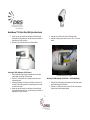
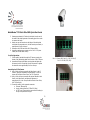
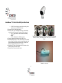
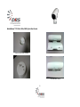
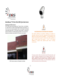
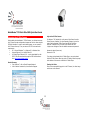
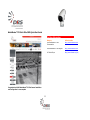
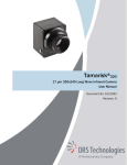
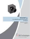
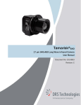
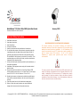
WatchMaster® IP Elite & Elite 3000 Quick Start Guide January 2013 Document Number 1012610 Version B Important Safety Instructions 1. 2. 3. 4. 5. 6. Read these instructions. Keep these instructions. Heed all warnings. Follow all instructions. Install in accordance with the manufacturer’s instructions. Do not defeat the purpose of the polarized or grounding-type plug. A polarized plug has two blades with one wider than the other. A grounding type plug has two blades and a third grounding prong. The wide blade or the third prong is provided for your safety. If the provided plug does not fit into your outlet, consult an electrician for replacement of the obsolete outlet. 7. Use only with the tripod or bracket specified by the manufacturer, or sold with the apparatus. 8. Installation of the equipment must comply with local and national electrical codes. 9. This product must be connected to a Power Over Ethernet IEEE 802.af compliant power source or a UL Listed “Class 2” power supply rated 12-24 V DC or 24 V AC minimum 13 W or 0.54 A. 10. Operating the camera at voltage levels outside the specified range may result in permanent damage to the unit and void the product warranty. 11. Clean the camera lens only with Kodak lens cleaning paper. 12. Failure to follow the proper procedure may cause permanent damage to the camera and void the product warranty. WARNING DEVICE SENSITIVE TO ELECTROSTATIC DISCHARGE The camera electronics and electronic interfaces are sensitive to electrostatic discharge. Please follow appropriate ESD procedures when handling the camera and during installation. For PoE installations, DRS strongly recommends the use of STP cabling and an earth grounded end point to ensure proper ESD immunity. For AC or DC powered installations, a properly earth grounded power source is strongly recommended. CAUTION To ensure a proper earth ground (between the DRS camera and a PoE switch) DRS strongly recommends the use of Shielded Twisted Pair (STP) cabling. Installations of DRS cameras using a STP cabling and a properly earth grounded PoE switch are tested to comply with industry immunity standards for Electro Static Discharge. Any other installation method may leave the camera at risk and void the warranty. ©Copyright 2012-2013, DRS TECHNOLOGIES, Inc. - All rights reserved. The contents of this document may not be reproduced in whole or in part without the written consent of the copyright owner. WatchMaster® IP Elite & Elite 3000 Quick Start Guide Important Legal and Regulatory Information Introducing WatchMaster® IP Elite Legal Consideration ALL STATEMENTS, INFORMATION, AND RECOMMENDATIONS IN THIS MANUAL ARE BELIEVED TO BE ACCURATE BUT ARE PRESENTED WITHOUT WARRANTY OF ANY KIND. NOTWITHSTANDING ANY OTHER WARRANTY HEREIN, ALL DOCUMENT FILES AND SOFTWARE ARE PROVIDED “AS IS” WITH ALL FAULTS. DRS DISCLAIMS ALL WARRANTIES, EXPRESSED OR IMPLIED, INCLUDING, WITHOUT LIMITATION, THOSE OF MERCHANTABILITY, FITNESS FOR A PARTICULAR PURPOSE AND NONINFRINGEMENT OR ARISING FROM A COURSE OF DEALING, USAGE, OR TRADE PRACTICE. IN NO EVENT SHALL DRS BE LIABLE FOR ANY INDIRECT, SPECIAL, CONSEQUENTIAL, OR INCIDENTAL DAMAGES, INCLUDING, WITHOUT LIMITATION, LOST PROFITS OR LOSS OR DAMAGE TO DATA ARISING OUT OF THE USE OR INABILITY TO USE THIS MANUAL, EVEN IF DRS HAS BEEN ADVISED OF THE POSSIBILITY OF SUCH DAMAGES This document provides information about WatchMaster® IP Elite Fixed Mount, Fixed Focal Length Infrared Camera. You can download all required documents including the more detailed user manual at drsinfrared.com. The camera system is an Internet Protocol (IP) networked solution, conforming to the Open Network Video Interface Forum (ONVIF™). The new WatchMaster® IP Elite 3000 series also includes NTSC/PAL Analog video. What’s in the Box Ensure that you have the following package contents WatchMaster® IP Elite Camera with the Back Cover attached and a brown Desiccant pack inside the cover for shipping o The WatchMaster® IP Elite 3000 series also includes a 90degree BNC Adapter already attached to the back of the camera WatchMaster® IP Elite Camera Base Mount WatchMaster® IP Elite Camera 4 Hole Axis Mount Adapter WatchMaster® IP Elite Camera Solar Shroud Hardware Kit with several small plastic bags containing o 1 - Cable Sealing Gland with electrical nut o 1 - O-Ring o 16 - #6-32 X 5/8” screws including 2 spares o 1 - White Desiccant for installation o 3 - Sealing washers with gasket including 1 spare o 3 - Stem Bumpers including 1 spare o 1 – Power Block (4-pin: IP Elite, 5-pin: IP Elite 3000) Export Control: This document contains technology controlled under the U.S. Export Administration Regulations (EAR), diversion contrary to U.S. Law is prohibited. Regulatory This product has been tested and found to comply with the limits of FCC Class A Part 15 Subpart B and CES-003. RoHS This product complies with the European ROHS directive. 2 WatchMaster® IP Elite & Elite 3000 Quick Start Guide Installing the IP Elite Camera Quick Start Guide (this guide) End User Licensing Agreement (EULA) You will need the following items (not included) before you can install the IP Camera (recommended tool list) Power source: PoE Switch, 12-24V DC or 24V AC IP Network Ethernet Cable (STP Cat5 recommended) Tripod or Mounting bracket for mounting the IP Camera A Phillips head #2 screwdriver 2 Open End Wrenches – 1 inch (25mm), OR adjustable wrenches A 6-inch scale OR ruler Torque screwdriver set to 10 inch-pounds (Electric or manual) Torx (hole in the middle) T10 Pin-In Security bit – 3.5 inch (90mm) in Length Hex Wrench RJ-45 connecter and RJ-45 Crimping Tool Suggested Tools for Analog Video (IP Elite 3000 only): o Coax Cable o Coax Cable Cutter/Stripper o BNC Connector o BNC Crimping Tool WatchMaster® IP Elite Components and Hardware Kit Cable Glands and Power Blocks for the WatchMaster® IP Elite 3000 (left) and WatchMaster® IP Elite (right) 3 WatchMaster® IP Elite & Elite 3000 Quick Start Guide Preparing the Cable 1. Disconnect power from any previously installed cable(s). 2. Take the number 2 Phillips head screwdriver and pierce a hole in the center of the cable gland. 3. If needed, pierce the smaller holes on the outer perimeter of the cable gland membrane for AC/DC power and RS-485 (IP Elite 3000 only) wires 4. Remove the electric nut from the sealing gland. 5. Place the O-ring (Orange) on the threaded end of the cable gland. This is necessary to insure a good seal. 6. Cut off the RJ-45/BNC connector if using existing cable 7. Feed existing or new cable(s) through the components in the following order: a. 4 Hole Axis Mount Adapter (4 hole flat surface facing the mating Standard Axis Bracket), if required b. Base Mount (Flat side first for Pelco Bracket) c. Electrical Nut (Convex side) of the supplied Cable Sealing Gland d. Bottom of the IP Camera body through the back hole below the connectors Recommended Tools Securing for IP66 (PoE only) 1. Slide the Ethernet cable through the threaded end of the cable sealing gland, with Orange O-Ring installed 2. Measure approximately 4.5 inches of cable slack from the end of the cable to the rubber grommet of the sealing gland. Use a scale to measure the length Recommend Tools for Analog Video (IP Elite 3000 only) 4 WatchMaster® IP Elite & Elite 3000 Quick Start Guide 3. 4. Attach one open end wrench onto the flange of the cable gland and tighten the compression nut, with the second open wrench, to approximately 8 in-lbs. of torque Assemble a new RJ45 head to the Cat 5 Ethernet Cable 5. 6. Assemble a new RJ45 head to the Cat 5 Ethernet Cable Assemble a mating power connector to the 2 AC or 2 DC power cables. IP66 (PoE only) Securing for IP66 (Ethernet & AC/DC Power): 1. Slide the Ethernet cable through the threaded end of the cable sealing gland, with Orange O-Ring installed 2. Slide the 2, 20 AWG power wires through the back side of the cable sealing gland 3. Measure approximately 4.5 inches of cable slack from the end of the cable to the rubber grommet of the sealing gland. Use a scale to measure the length 4. Attach one open end wrench onto the flange of the cable gland and tighten the compression nut, with the second open wrench, to approximately 8 in-lbs. of torque IP66 (Ethernet and AC/DC Power) Securing for IP66 (Analog & AC/DC Power – IP Elite 3000 Only) 1. 2. 5 Slide the Coax cable through the threaded end of the cable sealing gland, with Orange O-Ring installed Slide the 2, 20 AWG power wires (and any RS-485 wires) through the back side of the cable sealing gland WatchMaster® IP Elite & Elite 3000 Quick Start Guide 3. 4. 5. 6. Measure approximately 4.5 inches of cable slack from the end of the cable to the rubber grommet of the sealing gland. Use a scale to measure the length Attach one open end wrench onto the flange of the cable gland and tighten the compression nut, with the second open wrench, to approximately 8 in-lbs. of torque Assemble a new RJ45 head to the Cat 5 Ethernet Cable Assemble a mating power connector to the 2 AC or 2 DC power cables (and RS-485 cables if used). For all Configurations: 7. Pull the cable(s) taut back through the IP Camera, exposing the thread of the cable sealing gland out of the base of the IP Camera 8. Assemble the Electrical Nut back onto the gland and tighten the Nut securely until it is finger tight. Use the Hex wrench to tighten the electrical nut to approximately 8 in-lbs. of torque IP Elite 3000 Pin-Out Pins 1-3: Power (GND, 24V AC, 12-24 DC/24V AC) Pins 3-4: RS-485 (POS, NEG) Assembling the IP Elite Camera 9. Using 8 of the #6 screws, assemble the Base Mount, to the IP Camera. Tighten the 8 fasteners to approximately 10 in-lbs. of torque with the Electric Screw Driver, and T10 Security bit 10. Using 4 of the #6 screws, assemble the optional Standard 4 hole Mount, to the Base Mount, and tighten the fasteners to approximately 10 in-lbs. of torque with the Electric Screw Driver, and T10 Security bit 11. Connect the cable(s) to the respective connector: a. Ethernet: Ethernet Port b. Analog: Analog Video Out (IP Elite 3000 Only) c. AC/DC Power: Connect wires to power block according to the pin-outs pictured to the right: IP Elite Pin-Out 6 WatchMaster® IP Elite & Elite 3000 Quick Start Guide d. 12. 13. 14. 15. 16. 17. RS-485: Connect wires to power block according to the previous pin-outs (IP Elite 3000 only) Reconnect Power to the existing cable(s) Check for Solid LED on the Ethernet connector to acknowledge connectivity to the IP network. The status LED indicators are: e. LED 1: Solid Green for 10MB connection or Flashing Green for Activity f. LED 2: Solid Amber for 100MB connection. Place the supplied white desiccant into the Back Cover Assemble the Back Cover, to the IP Camera using two #6 screws and two Master Seal Washers (metal side against the head of the screw and gasket side against the camera body). Tighten the 2 fasteners to approximately 10 in-lbs. of torque Assemble the 2 Rubber Stem Bumpers onto the 2 detents in the concave surface of the Solar Shroud Snap the Solar Shroud, to the Base Mount The three possible configurations of the IP Elite: PoE Only (left), Ethernet and AC/DC (Center), and Analog & AC/DC Power (right – IP Elite 3000 Only) Camera with Base mount and Standard 4-Hole mount 7 WatchMaster® IP Elite & Elite 3000 Quick Start Guide Back Cover and White Desiccant Solar Shroud and Stem Bumpers Back Cover screws and Sealing Washer Fully assembled Camera 8 WatchMaster® IP Elite & Elite 3000 Quick Start Guide Mounting the IP Elite Camera The IP Elite camera can be mounted on a Tripod or Pelco or Axis Bracket. For Tripod mount, use IP Elite Tripod Adapter offered as an accessory. For Pelco Mount, secure the Camera Base Mount to the Standard Pelco Bracket (not provided) using #6-32 X 5/8” screws (not provided). For Axis Mount, secure the Standard 4-Hole Axis Adapter provided to mount to the Axis Bracket (not provided) using the Metric M5 screws (not provided). WARNING DEVICE SENSITIVE TO ELECTROSTATIC DISCHARGE The camera electronics and electronic interfaces are sensitive to electrostatic discharge. Please follow appropriate ESD procedures when handling the camera and during installation. For PoE installations, DRS strongly recommends the use of STP cabling and an earth grounded end point to ensure proper ESD immunity. For AC or DC powered installations, a properly earth grounded power source is strongly recommended CAUTION To ensure a proper earth ground (between the DRS camera and a PoE switch) DRS strongly recommends the use of Shielded Twisted Pair (STP) cabling. Installations of DRS cameras using a STP cabling and a properly earth grounded PoE switch are tested to comply with industry immunity standards for Electro Static Discharge. Any other installation method may leave the camera at risk and void the warranty. IP Elite Camera mounted on Standard Axis Bracket 9 WatchMaster® IP Elite & Elite 3000 Quick Start Guide Accessing the IP Elite Camera Login to the IP Elite Camera For Windows 7 OS, double click on the name of the Camera from the Device Discovery interface. For other Operating Systems, login to the router, find the attached IP Elite Camera and find its IP address. Enter the IP address of the IP Camera on the Browser URL line. A login screen will appear. Enter the default username and password. After installing the WatchMaster™ IP Elite Camera, you will need to access the IP Camera to make configuration changes and view live video using the DRS Web Interface. In order to make these changes, you can connect to the IP Camera from any PC on your network. The PC must meet below requirements OS - Microsoft Windows 7 or Windows XP or Windows Vista Internet Explorer 9.0 or Mozilla Firefox 8.0 VLC Media Player Software 2.0.0 – can be downloaded from the DRS IP Elite Camera directly through the DRS Web Interface or from http://www.videolan.org/vlc/ Username is admin (lower case) Password is 1234 If you have not downloaded the VLC Media Player, you can download from the IP Elite Camera. After login to the IP Camera, follow the prompt at the bottom of the screen to install the VLC Media Player. Device Discovery Viewing Live Video From Windows 7, click on Start/Computer/Network A list of devices connected to your network will appear Once you have successfully logged in to the IP Camera, live video image can be seen on the Browser. 10 WatchMaster® IP Elite & Elite 3000 Quick Start Guide For More Information Congratulations!! DRS WatchMaster® IP Elite Camera Installation and Configuration is now complete. 11 Category DRS WatchMaster IP Elite Documentation Online Location http://www.drsinfrared.com DRS WatchMaster IP Elite Support http://www.drsinfrared.com VLC Media Player http://www.videolan.org/vlc/