1
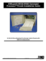
XRSuper6/XR20/XR40 Command
ProcessorTM Panels Installation Guide
22/26/42 Zone Burglary/Fire/Access Control Panels with
Built-in Communicator
2500 N. Partnership Boulevard Springfield, MO 65803
www.dmpnet.com
Digital Monitoring Products
LT-0624 (10/01)
MODEL XRSuper6/XR20/XR40
COMMAND PROCESSORTM
INSTALLATION GUIDE
FCC NOTICE
This equipment generates and uses radio frequency energy and, if not installed and used properly in strict accordance
with the manufacturer's instructions, may cause interference with radio and television reception. It has been type tested
and found to comply with the limits for a Class B computing device in accordance with the specification in Subpart J of
Part 15 of FCC Rules, which are designed to provide reasonable protection against such interference in a residential
installation. If this equipment does cause interference to radio or television reception, which can be determined by
turning the equipment off and on, the installer is encouraged to try to correct the interference by one or more of the
following measures:
Reorient the receiving antenna
Relocate the computer with respect to the receiver
Move the computer away from the receiver
Plug the compute into a different outlet so that computer and receiver are on different branch circuits
If necessary, the installer should consult the dealer or an experienced radio/television technician for additional
suggestions. The installer may find the following booklet, prepared by the Federal Communications Commission, helpful:
"How to identify and Resolve Radio-TV Interference Problems."
This booklet is available from the U.S. Government Printing Office, Washington D.C. 20402
Stock No. 004-000-00345-4
Copyright © 1995 - 2001 Digital Monitoring Products, Inc.
Information furnished by DMP is believed to be accurate and reliable.
This information is subject to change without notice.
Section
TABLE OF CONTENTS
Page
Panel Specifications ................................................................................ 1
1.1 Power supply ............................................................................................................. 1
1.2 Communication ......................................................................................................... 1
1.3 Panel zones .............................................................................................................. 1
1.4 Keypads .................................................................................................................... 1
1.5 Outputs ..................................................................................................................... 1
1.6 Enclosure specifications ........................................................................................... 1
Introduction ......................................................................................... 2
2.1 Description ................................................................................................................ 2
2.2 System configurations ............................................................................................... 2
2.3 Before you begin ....................................................................................................... 2
2.4 About this guide ........................................................................................................ 2
2.5 How to use this guide ................................................................................................ 2
System Components ................................................................................ 3
3.1 Description ................................................................................................................ 3
3.2 Wiring diagram .......................................................................................................... 3
3.3 Lightning protection ................................................................................................... 3
3.4 Command Processor Accessories ............................................................................ 3
Installation ........................................................................................... 5
4.1 Mounting the enclosure ............................................................................................. 5
4.2 Mounting keypads ..................................................................................................... 6
4.3 Wiring keypads ......................................................................................................... 6
Primary Power Supply ............................................................................. 6
5.1 AC terminals 1 and 2 ................................................................................................. 6
5.2 Transformer types ..................................................................................................... 6
Secondary Power Supply .......................................................................... 7
6.1 Battery terminals 3 and 4 .......................................................................................... 7
6.2 Earth ground ............................................................................................................. 7
6.3 Replacement period .................................................................................................. 7
6.4 Discharge/recharge ................................................................................................... 7
6.5 Battery supervision ................................................................................................... 7
6.6 XRSuper6/XR20/XR40 power requirements ............................................................. 7
Bell Output ........................................................................................... 9
7.1 Terminals 5 and 6 ...................................................................................................... 9
Keypad Data Bus .................................................................................... 9
8.1 Description ................................................................................................................ 9
8.2 Terminal 7 - RED ....................................................................................................... 9
8.3 Terminal 8 - YELLOW ................................................................................................ 9
8.4 Terminal 9 - GREEN ................................................................................................. 9
8.5 Terminal 10 - BLACK ................................................................................................. 9
8.6 Programming Connection ......................................................................................... 9
Smoke and Glassbreak Detector Output ....................................................... 9
9.1 Terminal 11 ............................................................................................................... 9
Burglary Zones .................................................................................... 10
10.1 Description .............................................................................................................. 10
10.2 Operational parameters .......................................................................................... 10
10.3 Zone response time ................................................................................................ 10
10.4 Keyswitch arming zone ........................................................................................... 10
Powered Zone for 2-Wire Smoke Detectors ................................................. 11
11.1 Terminals 25 and 26 ................................................................................................ 11
Annunciator Outputs ............................................................................. 12
12.1 Description .............................................................................................................. 12
12.2 Harness wiring ........................................................................................................ 12
12.3 Model 860 Relay Module ......................................................................................... 12
Telephone RJ Connector ........................................................................ 12
13.1 Description .............................................................................................................. 12
13.2 FCC registration ...................................................................................................... 12
13.3 Notification .............................................................................................................. 12
13.4 Ground start ............................................................................................................ 13
Section
TABLE OF CONTENTS
Page
Reset Jumpers J16 ............................................................................... 13
14.1 Description .............................................................................................................. 13
UNIVERSAL UL BURGLARY SPECIFICATIONS .................................................. 13
15.1 Introduction ............................................................................................................. 13
15.2 Wiring...................................................................................................................... 13
15.3 Police station phone numbers ................................................................................. 13
15.4 Bypass reports ........................................................................................................ 13
15.5 System maintenance .............................................................................................. 13
15.6 Cross zoning ........................................................................................................... 13
15.7 Ground Start ........................................................................................................... 13
15.8 UL Listed Receivers ................................................................................................ 13
UL 1023 SPECIFICATIONS ........................................................................ 14
Household Burglar-Alarm System Units ...................................................... 14
16.1 Bell cutoff ................................................................................................................ 14
16.2 Entry delay .............................................................................................................. 14
16.3 Exit delay ................................................................................................................ 14
16.4 Zone expansion on 4-wire bus ................................................................................ 14
UL 1610 and 1076 specifications .............................................................. 14
Central-Station and Proprietary Burglar-Alarm Units ..................................... 14
17.1 Opening/Closing reports ......................................................................................... 14
17.2 Automatic bell test ................................................................................................... 14
17.3 Proprietary dialer .................................................................................................... 14
UL 1635 SPECIFICATIONS ........................................................................ 15
Digital Burglar Alarm Communicator System Units ........................................ 15
18.1 Digital Dialer telephone number .............................................................................. 15
18.2 Entry delay .............................................................................................................. 15
18.3 Exit delay ................................................................................................................ 15
18.4 Test frequency ......................................................................................................... 15
18.5 Automatic bell test ................................................................................................... 15
18.6 Grade B Central Station .......................................................................................... 15
UL 365 and 609 SPECIFICATIONS .............................................................. 15
Police Station Connected and Local Burglar Alarm Units and Systems ................ 15
19.1 Entry delay .............................................................................................................. 15
19.2 Grade A bell ............................................................................................................ 15
19.3 Bell cutoff ................................................................................................................ 15
19.4 Automatic bell test ................................................................................................... 15
19.5 Grade A Mercantile ................................................................................................. 15
19.6 Mercantile Safe and Vault ........................................................................................ 15
19.7 Line security for Police Connect .............................................................................. 15
UNIVERSAL UL and NFPA FIRE ALARM SPECIFICATIONS .................................... 16
20.1 Introduction ............................................................................................................. 16
20.2 Wiring...................................................................................................................... 16
20.3 Police station phone number ................................................................................... 16
20.4 System maintenance .............................................................................................. 16
20.5 Audible alarm .......................................................................................................... 16
20.6 Fire zone programming ........................................................................................... 16
20.7 Ground Start ........................................................................................................... 16
20.8 UL Listed Receivers ................................................................................................ 16
UL 985 NFPA 72 (chapter 2) SPECIFICATIONS .............................................. 16
Household Fire Warning System Units ........................................................ 16
21.1 Bell output definition ................................................................................................ 16
21.2 Indicating Circuit Supervision .................................................................................. 16
CALIFORNIA STATE FIRE MARSHAL SPECIFICATIONS ........................................ 17
22.1 Bell output definition ................................................................................................ 17
23.1 Troubleshooting Section .......................................................................................... 17
24.1 Multiple Indicating Circuit Module Installation .......................................................... 18
24.2 Installation for Derived Channel burglary ................................................................. 19
Introduction
Panel Specifications
1.1
1.2
1.3
1.4
Power supply
Transformer Input: 16.5 VAC 40VA (Models 320 wire-in or 321 plug-in)
16.5 VAC 20VA (Model 324 plug-in)
Standby Battery: 12 VDC 7.0Ah (40VA transformer charges up to 2 batteries)
Auxiliary Output: 12 VDC at 500mA
Bell Output: 12 VDC at 1.5 Amps with 40VA transformer, 600mA with 20VA transformer
Smoke Detector Output: 12 VDC at 100mA
All circuits inherent power limited
Communication
Built-in SDLC Digital Dialer communication to DMP Model SCS-1 Receivers
Built-in 4-2 communication to non-DMP receivers
Built-in M2E (Radionics Modem IIe) communication to non-DMP receivers (XRSuper6/XR20/XR40 only)
Built-in CID (Contact ID) communication to non-DMP receivers
Any panel can operate as a local system.
Panel zones
Nine 1k Ω EOL burglary zones (zones 1 to 9), (zones 1 to 5 on XRSuper6)
One 3.3k Ω EOL Class B powered fire zone with reset capability (zone 6 on XRSuper6; zone 10 on, XR20, and XR40)
Keypads
You can connect up to four supervised keypads to the XRSuper6/XR20 panels and eight supervised keypads on
the XR40.
• 16 or 32 character alphanumeric keypads
• 10-zone LED keypads
In addition, the following zone expanders can be added to the XRSuper6/XR20/XR40 panels:
• Four and single point zone expanders
• Single point PIR and glassbreak detectors
• One 738A Ademco Wireless interface for up to 32 points of zone expansion
• One FA426 Wireless receiver for up to 16 points of zone expansion (Two on the XR40)
When using the FA426 Wireless Receiver, the XRSuper6/XR20 allows unsupervised devices to be added to
address five.
1.5
1.6
Outputs
The XRSuper6/XR20/XR40 panels provide four open collector outputs rated for 50mA each. A Model 300 Output
Harness is required. The open collector outputs provide the ground connection for a positive voltage source.
Enclosure specifications
The XRSuper6/XR20/XR40 panel ships in an enclosure with EOL resistors, battery leads, user's guide, and
programming sheet.
Size:
Weight:
Color:
Construction:
12.5" W x 11.5" H x 3.5" D
4 lbs
Gray
20 gauge cold rolled steel
XRSuper6/XR20/XR40 Installation Guide
2500 N. Partnership Boulevard Springfield, MO 65803
www.dmpnet.com
Digital Monitoring Products
1
Introduction
Introduction
2.1
2.2
2.3
Description
The DMP XRSuper6/XR20/XR40 Command Processor® panels are powerful 12 VDC burglary and fire communicator
panels with battery backup. The panels provide nine on-board burglary zones and one on-board 12 VDC Class B
powered fire zone. The XRSuper6 provides five burglary and one fire zone. The fire zone has a reset capability
to provide for 2-wire smoke detectors, relays, or other latching devices. The panels can communicate to one or
two DMP SCS-1 Receivers using SDLC digital dialer, 4-2, or Contact ID (CID) reporting formats. In addition, the
XRSuper6/XR20/XR40 can communicate using the Radionics Modem IIe format.
System configurations
The panels can be programmed to operate as either an All/Perimeter system that provides one Perimeter area
and one Interior area, or as a Home/Sleep/Away system that provides one Perimeter, one Interior, and one
Bedroom area. The Bedroom area can include any protection devices the user wants disarmed during their
sleeping hours and armed in the Away mode. In addition, the XR20/XR40 can operate as a four area system.
Before you begin
Before installing the panel, we recommend you read through the entire contents of this guide. Familiarize
yourself with the features of the panel and the key points to remember during the installation. Be sure to read
and understand all of the caution statements printed in bold italics.
In addition to this installation guide, you should also read through and familiarize yourself with these other
product documents:
•
•
•
•
2.4
XRSuper6/XR20/XR40 Programming Guide (LT-0305)
XRSuper6 Program Information Sheet (LT-0621)
XRSuper6 Security Command User's Guide (LT-0622)
XR20 Program Information Sheet (LT-0302)
• XR20 Security Command User's Guide (LT-0303)
• XR40 Program Information Sheet (LT-0493)
• XR40 Security Command User's Guide (LT-0494)
About this guide
The information contained in this guide is organized into three sections: Table of Contents, Introduction, and
Installation.
• The Table of Contents at the front of this guide lists all of the headings and subheadings used throughout
each section and the page number where the information can be found.
• The Introduction section gives you an overview of the various components that go into a
panel system and diagrams some typical system configurations. This section gives descriptions of the
panel, keypads, and accessory modules and provides details on how each of them operate together in the
system.
• The Installation section begins with mounting instructions for the enclosure and takes you through the
proper way to power up the panel prior to programming.
Caution notes
Throughout this guide you will see caution notes containing information you need to know when installing the
panel. These cautions are written with a bold, italicized introductory clause followed by a detailed description of
the caution. See the example shown below.
Always ground the panel before applying power to any devices: The panel must be properly grounded before
connecting any devices or applying power to the panel. Proper grounding protects against Electrostatic
Discharge (ESD) that can damage system components.
Whenever you see a caution note, make sure you completely read and understand its information. Failing to
follow the caution note can cause damage to the equipment or improper operation of one or more components in
the system.
2.5
How to use this guide
To locate information about the installation of the panel, first go to the Table of Contents at the front of this
guide. Find the subject heading that closely describes the information you need and turn to the section number
shown to the right of the heading.
The text that follows the heading has been written to provide as much information about the subject as
possible. If you can't find the information you need under that heading, try scanning through a few of the
headings before and after and reading the text under those that sound similar.
XRSuper6/XR20/XR40 Installation Guide
Digital Monitoring Products
2
www.dmpnet.com
2500 N. Partnership Boulevard Springfield, MO 65803
Introduction
System Components
3.1
3.2
3.3
3.4
Description
The DMP system is made up of an alarm panel with built in communicator, an enclosure, a 16.5 VAC transformer,
and a 12 VDC 7.0 Ah battery. You can add Security Command keypads to the system and can also connect auxiliary
devices to the panel's open collector outputs to expand the basic system. Combined current requirements of
additional modules may require an auxiliary power supply. Refer to the Standby Battery Power Calculation section
in this guide when calculating power requirements. In addition, up to 32 points of zone expansion can be added to
the XR40, 16 points to the XR20, and 16 points to the XRSuper6.
Wiring diagram
The system wiring diagram in Figure 1 shows some of the accessory devices you can connect for use in various
applications. A complete description of each module follows. Zone expanders can be added to the XRSuper6,
XR20, and XR40. Wireless interface can also be added to the XRSuper6, XR20, and XR40.
Lightning protection
Metal Oxide Varistors and Transient Voltage Suppressors help protect against voltage surges on input and output
circuits. A transorb is provided for the Smoke Detector Output Circuit (Terminal 11). This transient protection
provides additional resistance to electrical surges such as lighting. Additional surge protection is available by
installing the DMP 370 or 370RJ Lightning Suppressors.
Command Processor Accessories
You can connect any combination (up to four on XRSuper6 and XR20, and up to eight on XR40) of Model 670,
770, and 771 vacuum fluorescent, 790, 791, and 793 LCD, or 692 LED Security Command Keypads to the 4-wire
keypad data bus provided by the panel on terminals 7, 8, 9, and 10. Also, you can connect Model 714, 715, 7148, 714-16, 715-8, 715-16 zone expanders to the XR40, XR20, or XRSuper6 keypad bus. Additionally, you can
connect one Model 738A Ademco Interface Module or one Model FA426 Wireless Receiver to the XRSuper6, XR20,
and XR40 keypad bus. You can connect an additional Model FA426 Wireless Receivers to the XR40 keypad bus.
XRSuper6/XR20/XR40 Installation Guide
2500 N. Partnership Boulevard Springfield, MO 65803
www.dmpnet.com
Digital Monitoring Products
3
Introduction
3.5 XRSuper6/XR20/XR40 wiring diagram
The Class 2, Class 3, and power-limited fire alarm circuits are installed using CL3, CL3R, or
CL3P, or substitute cable permitted by the National Electric code, ANSI/NFPA 70, and the Class
2, Class 3, and power-limited fire alarm circuit conductors extending beyond the cable jacket
are separated a minimum of 1/4 in. or by nonconductive tubing or by a nonconductive barrier.
Output Header J11
All outputs must be connected to
devices located within the same room
as the control panel.
DMP transformers:
Model 320
16.5 VAC 40VA
Class 2 wire-in
Use DMP Model 300 Harness.
J11
J16
Command Processor Reset
Model 324
16.5 VAC 20VA
Class 2 plug-in
J4
RJ Cable Monitor J7
Use DMP Model 306 Harness
J7
AC wiring must be in conduit and exit
out the left side of the panel enclosure
RJ SUP
Phone Jack Connector
Secondary Power Supply
1.2 Amps max. charging
current. Use only 12 VDC
rechargable batteries. DMP
Model 367. Replace every 3
- 5 years.
Wiring on
terminals 5 thru
17 must exit to
the right and
maintain a 1/4"
separation from
the AC and
battery positive
wiring.
Front Tamper
U11
J8
Programmer Header J8
Use DMP Model 330 Harness
AC
+B
-B BELL GND RED YEL GRN BLK SMK Z1 GND
Z2
Z3
GND
Z4
Z5
GND
Z6
Z7 GND
Z8
Z9
Z10+ Z10-
ZONE 10
AC
See detail below for
XRSuper6 panel only
ZONE 9
PROG
Plug into
120 VAC
outlet not
controlled
by switch.
1
2
3
4
EPROM
Socket
Model 321
16.5 VAC 40VA
Class 2 plug-in
Rear Tamper
Tamper protection when
required for Model 350A
Attack Resistant
Enclosure.
Household System
An alarm sounding
device must be installed
indoors so that it is
clearly heard in all
sleeping areas.
1K Ω 1K Ω
1K Ω 1K Ω
Smoke Output
100mA @ 10.4 - 13.2 VDC
Terminal 11
1K Ω
1K Ω
ZONE 8
ZONE 7
ZONE 6
ZONE 5
ZONE 3
1K Ω 1K Ω
ZONE 4
ZONE 2
BLACK
ZONE 1
GREEN
22 GA. MIN
22 GA. MIN YELLOW
22 GA. MIN
Cold Water Pipe Earth Ground
22 GA. MIN RED
Bell
10.4 - 13.2 VDC
Total current:
1.5 Amps max. w/ 40
VA
600mA w/20 VA
RED
Maximum AC wire distance
With 16 gauge wire: 70 feet
With 18 gauge wire: 40 feet
BLACK
16 - 18 gauge wire
1K Ω
Zone 10 compatibility
identifier: A
Maximum operating range: 8.8
VDC - 14.2 VDC.
Red
Black
4-wire smoke detector
Bell
Smoke
Detector
Power
Supervision
Relay
Up to 500mA auxiliary
current at 10.4 - 13.2
VDC from Terminal 7.
+-
2-wire
smoke
detector
Heat detectors, manual pull
stations, or any other shorting
device. Unlimited number of units.
See the XRSuper6/XR20/XR40
Installation Guide (LT-0624) for a list of
approved 2-wire smoke detectors.
3.3k Ω
DMP Model 309
ZONE EXPANDER
Model 714
15mA @ 12 VDC
Models 714-8, 714-16
20mA @ 12 VDC
Keypads
Models 670, 770, 771
100mA @ 8 - 16 VDC
125mA with display lit
ZONE EXPANDER
Model 715
15mA @ 12 VDC
Models 715-8, 715-16
20mA @ 12 VDC
Models 690, 790,
791, 793
100mA @ 8 - 16 VDC
STAY
POWER
INSTANT
1
2
3
4
5
6
7
8
9
10
STAY
1
ABC
5
MNO
9
INSTANT
2
DEF
6
PQR
0
BYPASS
CODE
3
4
G H I
7
Z3 GND Z4 Z5
Z6+ Z6-
ZONE 6
ARMED
TRBL
ZONE 4
READY
ZONE 5
Model 692
75mA @ 8 -16 VDC
JKL
8
STU
VWX
SPECIAL
COMMAND
2-wire
smoke
detector
YZ
Detail for XRSuper6 only
Figure 1
XRSuper6/XR20/XR40 Installation Guide
Digital Monitoring Products
4
www.dmpnet.com
2500 N. Partnership Boulevard Springfield, MO 65803
Installation
Installation
4.1
Mounting the enclosure
The metal enclosure must be mounted in a secure, dry place to protect the panel from damage due to tampering
or the elements. It is not necessary to remove the PCB when installing the enclosure. The PCB may be installed
in the standard 340 enclosure, or the optional 349 enclosure, or the optional 350A Grade A enclosure.
Dual 1/2" and 3/4" Conduit Knockout
J11
J16
1
2
3
4
Command Processor Reset
J4
Phone Jack Connector
EPROM Socket
U11
1
2
AC
AC
3
+B
4
-B
5
6
7
8
BELL GND RED
10
9
YEL GRN
11
BLK SMK
12
13
Z1
GND
14
15
Z2
Z3
16
GND
17
18
Z4
Z5
19
GND
20
21
Z7
Z6
22
GND
23
Z8
24
Z9
25
26
Z10+ Z10-
Enclosure Mounting Holes
Battery shelf
Figure 2: XRSuper6/XR20/XR40 in standard 340 enclosure
Accessory Module
Mounting Holes
Accessory Module
Mounting Holes
Dual 1/2" and 3/4" Conduit Knockouts
T amper Switch
Mounting Holes
Enclosure Mounting Holes
J1 1
J16
1
2
3
4
Reset Jumper
J4
Phone Jack Connector
EPROM Socket
U1 1
1
AC
2
AC
3
+B
4
5
6
7
8
-B BELL GND RED YEL
9
10
11
GRN BLK SMK
12 13
Z1 GND
14
Z2
15
Z3
16
GND
17
Z4
18
Z5
19
GND
20
Z6
21
Z7
22
GND
23
Z8
24
Z9
25
26
Z10+ Z10-
Enclosure Mounting Holes
Battery Shelf
Dual 1/2" and 3/4" Conduit Knockouts
Figure 2A: XRSuper6/XR20/XR40 in optional 349 Enclosure
XRSuper6/XR20/XR40 Installation Guide
2500 N. Partnership Boulevard Springfield, MO 65803
www.dmpnet.com
Digital Monitoring Products
5
Installation
4.2
Mounting keypads
Security Command keypads have removable covers that allow you to easily mount the base to a wall or other flat
surface using the screw holes provided on each corner.
For mounting keypads on solid walls, or for applications where conduit is required, use a DMP 695, 696, 775, or
776 keypad conduit backbox.
4.3
Wiring keypads
Keypad data bus
The keypad data bus consists of a 4-wire cable that provides 12 VDC power, data in, data out, and a panel
common. You can connect keypads in parallel on one 4-wire cable or provide a separate cable run back to the
panel for each keypad.
Three factors determine the performance characteristics of the keypad bus: the length of wire used, the number
of devices connected, and the voltage at each device. You can connect devices in parallel on the same cable, or
provide separate runs back to the panel.
When planning a keypad bus installation, keep in mind the following three specifications:
1. Maximum distance for any one keypad bus circuit (length of wire) is 2,500 feet.
2. Maximum number of devices per 2,500 feet circuit is 40. This number can be increased to 50 if the wire
run remains less than 2,000 feet.
3. Maximum voltage drop between the panel (or auxiliary power supply) and any device is 2.0 VDC. For
example, if the voltage across the red and black wires at the panel is 13.8 VDC, the voltage measured at each
device on the circuit must be equal to or greater than 11.8 VDC.
If the voltage at any device, including a 710 module, is less than the required level, an auxiliary power supply
should be added at the end of the circuit. The voltage drop can be reduced by increasing the gauge of wire used
on the circuit. The 2.0 VDC rule applies to keypad data bus circuits powered either by the panel or by an
auxiliary power supply.
Note: To troubleshoot voltage drop, read the voltage of the last device on the keypad bus.
Refer to the 710 Bus Splitter/Repeater Installation Sheet, LT-0310 (Document No. 0310 on DMP Fax) for
information concerning keypad wiring distances and capacities.
Primary Power Supply
5.1
AC terminals 1 and 2
Connect the transformer wires to terminals 1 and 2 on the panel. Use no more than 70 ft. of 16 gauge, or 40
ft. of 18 gauge, wire between the transformer and the panel.
Always ground the panel before applying power to any devices: The panel must be properly grounded before
connecting any devices or applying power to the panel. Proper grounding protects against Electrostatic
Discharge (ESD) that can damage system components. See Earth ground, in the Secondary Power Supply
section.
5.2
Transformer types
The larger transformer for the panel is 16.5 VAC 40VA, which provides up to 1.5 Amps of bell output current,
500mA of auxiliary current, and 100mA of smoke detector output. You can use either the Model 320 wire-in or
321 plug-in transformer with the panel. The total current available is limited by the total battery standby
requirements of the installation. When the DMP Model 324 16.5 VAC 20VA plug-in transformer is used, the bell
output current is reduced to 600mA.
The transformer must be connected to a 120 VAC 60 Hz commercial power outlet that is not controlled by a wall
switch. Never share the transformer output with any other equipment.
XRSuper6/XR20/XR40 Installation Guide
Digital Monitoring Products
6
www.dmpnet.com
2500 N. Partnership Boulevard Springfield, MO 65803
Installation
Secondary Power Supply
6.1
Battery terminals 3 and 4
Connect the black battery lead to terminal 4 on the panel and to the negative terminal of the battery. The
negative terminal connects to the enclosure ground internally through the panel circuit board. Connect the red
battery lead to terminal 3 on the panel and to the positive terminal of the battery. Observe polarity when
connecting the battery. The panel can charge up to two batteries.
Use sealed lead-acid batteries only: Use the DMP Model 367, 12 VDC 7.0Ah sealed lead-acid rechargeable
battery. Batteries supplied by DMP or manufactured by Eagle Picher or Yuasa have been tested to ensure proper
charging with DMP products.
GEL CELL BATTERIES CANNOT BE USED WITH THE XRSuper6/XR20/XR40 PANEL.
6.2
6.3
6.4
Earth ground
Terminal 4 of the panel must be connected to earth ground using 14 gauge or larger wire to provide proper
transient suppression. DMP recommends connecting to a metal cold water pipe or ground rod only. Do not
connect to electrical conduit or a telephone company ground.
Replacement period
DMP recommends the battery be replaced every 3 to 5 years under normal use.
Discharge/recharge
The panel battery charging circuit float charges at 13.9 VDC at a maximum current of 1.2 Amps using a 40VA
transformer. The total current available is reduced by the combined auxiliary current draw from terminals 7, 11,
and 25. The various battery voltage levels are listed below:
Battery Trouble:
Battery Restored:
6.5
Below 11.9 VDC
Above 12.6 VDC
Battery supervision
The panel tests the battery once every hour when AC power is present. The test lasts for five seconds. A load
is placed on the battery and if its voltage falls below 11.9 VDC a low battery is detected. If AC power has failed,
a low battery is detected any time the battery voltage falls below 11.9 VDC.
If a low battery is detected with AC power present, the test is repeated every two minutes until the battery
charges above 12.6 VDC; the battery restored voltage. If a faulty battery is replaced with a fully charged
battery, the restored battery will not be detected until the next two minute test is done.
6.6
XRSuper6/XR20/XR40 power requirements
During AC power failure, the panel and all auxiliary devices connected draw their power from the battery. All
devices must be taken into consideration when calculating the battery standby capacity. On the following page
is a list of the power requirements of the panel. Add the additional current draw of Security Command keypads,
smoke detector output, and any other auxiliary devices used in the system for the total current required. The
total is then multiplied by the total number of standby hours required to arrive at the total Ampere/hours
required.
XRSuper6/XR20/XR40 Installation Guide
2500 N. Partnership Boulevard Springfield, MO 65803
www.dmpnet.com
Digital Monitoring Products
7
Installation
6.7 XRSuper6/XR20/XR40 STANDBY BATTERY POWER CALCULATIONS
Standby Current
Command Processor Panel
Active Zones 1-9
Qty _____ x
Active Zone 10 (zone 6 on XRSuper6)
2-Wire Smoke Detectors
Qty _____ x
50mA
1.6mA
4mA
.1mA
Alarm Current
______
______
______
______
mA
mA Qty _____ x
mA
mA Qty _____ x
Bell Output
50mA
*2mA
30mA
.1mA
______ mA
______ mA
______ mA
______ mA
1500mA max. ______ mA
770 and 771 Keypads
Active Zones (EOL installed)
Annunciator (ON)
Qty _____ x
Qty _____ x
100mA ______ mA Qty _____ x 100mA ______ mA
1.6mA ______ mA Qty _____ x *2mA ______ mA
Qty _____ x 20mA ______ mA
690, 790, 791, and 793 Keypads
Active Zones (EOL installed)
Qty _____ x
Qty _____ x
100mA ______ mA Qty _____ x 100mA ______ mA
1.6mA ______ mA Qty _____ x *2mA ______ mA
692 Keypads
Qty _____ x
30mA ______ mA Qty _____ x
70mA ______ mA
710 Bus Splitter/Repeater
Qty _____ x
30mA ______ mA Qty _____ x
30mA ______ mA
711 or 714 Zone Expander
Active Zones (EOL installed)
Qty _____ x
Qty _____ x
7mA ______ mA Qty _____ x
1.6mA ______ mA Qty _____ x
7mA ______ mA
*2mA ______ mA
715 Zone Expander
Active Zones (EOL installed)
2-Wire Smokes
Qty _____ x
Qty _____ x
Qty _____ x
7mA ______ mA Qty _____ x
4mA ______ mA Qty _____ x
.1mA ______ mA Qty _____ x
7mA ______ mA
30mA ______ mA
.1mA ______ mA
714-8 or 714-16 Point Zone Expanders
Active Zones (EOL installed)
Qty _____ x
20mA ______ mA
1.6mA ______ mA Qty _____ x
20mA ______ mA
*2mA ______ mA
715-8 or 715-16 Point Zone Expanders
Active Zones (EOL installed)
2-Wire Smokes
Qty _____ x
Qty _____ x
20mA ______ mA
4mA ______ mA Qty _____ x
.1mA ______ mA Qty _____ x
20mA ______ mA
30mA ______ mA
.1mA ______ mA
Qty _____ x
30mA ______ mA
1.6mA ______ mA Qty _____ x
30mA ______ mA
*2mA ______ mA
20mA ______ mA
733 Wiegand Interface
Active Zones (EOL installed)
Annunciator (ON)
738A Ademco Wireless Interface
w/Receiver
75mA ______ mA
75mA ______ mA
FA426 16 Point Receiver
50mA ______ mA
50mA ______ mA
740/741/743 SC Keypads
Active Zones (EOL installed)
Annunciator (ON)
Qty _____ x
Qty _____ x
50mA ______ mA Qty _____ x 100mA ______ mA
1.6mA ______ mA Qty _____ x *2mA ______ mA
Qty _____ x 20mA ______ mA
Auxiliary Powered Devices on
Terminals 7 and 11
(Other than keypads)
______ mA
Total Standby ___________ mA
______ mA
Total Alarm ____________ mA
Total Standby ____________ mA x number of standby hours needed ______ = ___________ mA/hours
Total Alarm + ___________ mA/hours
Total ___________ mA/hours
x _.001_____
= ___________ A/hours required
* Based on 10% of active zones
in alarm condition
XRSuper6/XR20/XR40 Installation Guide
Digital Monitoring Products
8
www.dmpnet.com
2500 N. Partnership Boulevard Springfield, MO 65803
Installation
Bell Output
7.1
Terminals 5 and 6
Nominal 12 VDC is supplied by terminal 5 on the panel to power alarm bells or horns. The output is rated for a
maximum of 1.5 Amps with a 40VA transformer and 600mA with a 20VA transformer. This output can be
steady, pulsed, or Temporal Code 3 depending upon the Bell Action specified in Output Options programming.
Terminal 6 is the ground reference for the bell circuit.
Keypad Data Bus
8.1
8.2
8.3
8.4
8.5
8.6
Description
Terminals 7, 8, 9, and 10 of the panel are designated as the keypad data bus. In addition to keypads, the
XRSuper6/XR20/XR40 allows the connection of any combination of zone expanders, 5845LX Glassbreak
Detectors, and 6155LX PIRs, to the data bus up to the maximum of four devices. The XRSuper6 allows the
connection of four zones on address one.
Terminal 7 - RED
Nominal 12 VDC is supplied at terminal 7 to power Security Command keypads and zone expanders. This is also
where power for any auxiliary device is supplied. The ground reference for terminal 7 is terminal 10. The
maximum output is rated at 500mA. All auxiliary devices totaled together must not exceed the panel's
maximum current rating of 500mA.
Terminal 8 - YELLOW
Data receive from keypads and zone expanders.
Terminal 9 - GREEN
Data transmit to keypads and zone expanders.
Terminal 10 - BLACK
Terminal 10 is the ground reference for Security Command keypads, zone expanders, and any auxiliary devices
being powered by terminals 7 and 11.
Programming Connection
A locking 4-pin header (J8) is provided to connect a keypad when using a DMP Model 330 Programming Cable.
This provides a quick and easy connection for programming the panel.
Smoke and Glassbreak Detector Output
9.1
Terminal 11
Nominal 12 VDC at 100mA maximum (shared by terminal 25) is supplied at terminal 11 to power 4-wire smoke
detectors or other auxiliary powered devices. This output can be turned off by the user for 5 seconds using the
Sensor Reset Menu Option. Terminal 10 is the ground reference for terminal 11.
XRSuper6/XR20/XR40 Installation Guide
2500 N. Partnership Boulevard Springfield, MO 65803
www.dmpnet.com
Digital Monitoring Products
9
Installation
Burglary Zones
10.1 Description
The XR20/XR40 terminals 12 to 24 are the nine burglary zones. For programming purposes, the zone numbers
are 1 to 9. The zone configurations on terminals 12 to 24 are described below. The XRSuper6 terminals 12 to
18 are the five burglary zones with terminal 16 providing the ground for zone 5.
Terminal
12
13
14
15
16
17
18
Function
Zone 1 voltage sensing
Ground for zones 1 & 2
Zone 2 voltage sensing
Zone 3 voltage sensing
Ground for zones 3 & 4 (& 5 on XRSuper6)
Zone 4 voltage sensing
Zone 5 voltage sensing
Terminal
19
20
21
22
23
24
Function
Ground for zones 5 & 6
Zone 6 voltage sensing
Zone 7 voltage sensing
Ground for zones 7, 8, & 9
Zone 8 voltage sensing
Zone 9 voltage sensing
The voltage sensing terminal measures the voltage flowing through the 1k Ohm End-of-Line resistor to the
zone's ground terminal. Dry contact sensing devices can be used in series (normally-closed) or in parallel
(normally-open) with any of the burglary protection zones.
10.2 Operational parameters
Each burglary protection zone detects three conditions: open, normal, and short.
The parameters for each are listed below:
Condition
Resistance on zone
Voltage on right terminal
Open
over 1300 ohms
over 2.0 VDC
Normal
600 to 1300 ohms
1.2 to 2.0 VDC
Short
under 600 ohms
under 1.2 VDC
1K Ohm
Normally
Closed
1K Ohm
Normally Open
1K Ohm
Combination Normally Open
and Normally Closed
Figure 3: Protection zone contact wiring
10.3 Zone response time
A condition must be present on a zone for 500 milliseconds before it is detected by the panel. Ensure detection
devices used on the protection zones are rated for use with this delay.
10.4 Keyswitch arming zone
Momentary keyswitches
You can use a momentary keyswitch on a zone programmed as an Arming type for use in arming and disarming
the system without a code.
XRSuper6/XR20/XR40 Installation Guide
Digital Monitoring Products
10
www.dmpnet.com
2500 N. Partnership Boulevard Springfield, MO 65803
Installation
Powered Zone for 2-Wire Smoke Detectors
11.1 Terminals 25 and 26
A resettable 2-wire Class B powered zone is provided on terminals 25 (positive) and 26 (negative) of the panel.
For programming purposes, the zone number is 10 on the XR20/XR40 and zone 6 on the XRSuper6. The zone
uses a Model 309, 3.3k Ohm EOL resistor (provided with the panel) and has an operating range of 8.8 to 14.2
VDC.
Power is dropped from zone 10 any time a Sensor Reset is performed on the panel. Whenever non-Fire and nonSupervisory zone types are used on zone 10, make the appropriate adjustments to the zone's Armed Action to
prevent false alarms from occurring.
The UL compatibility identifier is: A.
Manufacturer
Model
Detector ID
Base
Base ID
# of
Detectors
XR
Panel
Zone Expander
Detection Systems
DS282
B
None
N/A
10
10/20
715, 715-8, 715-16
Detection Systems
DS282TH
B
None
N/A
10
10/20
715, 715-8, 715-16
Detection Systems
DS250
B
MB2W
A
10
10/20
715, 715-8, 715-16
Detection Systems
DS250TH
B
MB2W/MB2WL
A
10
10/20
715, 715-8, 715-16
Detection Systems
DS250HD
B
MB2W/MB2WL
A
10
10/20
715, 715-8, 715-16
DMP/Hochiki
SLK-835
HD-5
HSB-200, HSB-200N
HB-55
7
6/10/20
715, 715-8, 715-16
DMP/Hochiki
SLR-835
HD-3
NS6-100
HB-55
7
6/10/20
715, 715-8, 715-16
DMP/Hochiki
SLR-835B
HD-6
None
N/A
7
6/10/20
715, 715-8, 715-16
Sentrol/ESL
429AT
S09A
None
N/A
12
10/20
715, 715-8, 715-16
Sentrol/ESL
521B
S09A
None
N/A
12
10/20
715, 715-8, 715-16
Sentrol/ESL
521BXT
S09A
None
N/A
12
10/20
715, 715-8, 715-16
System Sensor
1100
STD
None
N/A
10
20
715
System Sensor
1151
STD
B110LP
N/A
10
20
715
System Sensor
1400
STD
None
N/A
10
10/20
715
System Sensor
1451
STD
B401, B401B
N/A
10
10/20
715
System Sensor
2100
STD
None
N/A
10
10/20
715
System Sensor
2400
STD
None
N/A
10
10/20
715
System Sensor
2451
STD
B401, B401B, DH400
N/A
10
10/20
715
System Sensor
1451DH
STD
DH400
N/A
10
10/20
715
System Sensor
2100T
STD
None
N/A
10
10/20
715
System Sensor
2400AT
STD
None
N/A
10
10/20
715
System Sensor
2400AIT
STD
None
N/A
10
10/20
715
System Sensor
2400TH
STD
None
N/A
10
10/20
715
System Sensor
2451TH
STD
B401, B401B
N/A
10
10/20
715
Figure 4: Compatible 2-wire smoke detectors
XRSuper6/XR20/XR40 Installation Guide
2500 N. Partnership Boulevard Springfield, MO 65803
www.dmpnet.com
Digital Monitoring Products
11
Installation
Annunciator Outputs
12.1 Description
The four annunciator outputs can be programmed to indicate the activity of the panel's zones or conditions
occurring on the system. Annunciator outputs do not provide a voltage but instead switch to ground voltage
from another source. The outputs can respond to any of the conditions listed below:
1)
2)
3)
4)
5)
6)
Activation by zone condition: Steady, Pulse, Momentary, or Follower
Manually from the Security Command keypad
Communication failure
Armed area annunciation
Fire Alarm or Fire Trouble
Ambush alarm
7)
8)
9)
10)
11)
Exit and Entry timers
System Ready
Ground start activation
Cellular Backup
Late to Close
12.2 Harness wiring
The open collector outputs are accessible by installing the DMP 300 Harness on the 4-pin header labeled J11.
The output locations are shown below. For UL applications, devices connected to the outputs must be located
within the same room as the panel.
Output
1
2
Color
Red
Yellow
Wire
1
2
Output
3
4
Color
Green
Black
Wire
3
4
12.3 Model 860 Relay Module
You may connect a Model 860 Relay Module to the panel to provide relays for the annunciator outputs. These
relays can be used for electrical isolation between the alarm panel and other systems or for switching voltage to
control various functions. The module includes one relay and provides three additional sockets for expansion of
up to four relays. A 4-wire harness is also provided that connects the Model 860 to the DMP panel.
The 860 mounts inside the panel enclosure using the 3-hole mounting configuration. Plastic standoffs are provided
with the module for ease of installation. Power is supplied to the relay coils from the panel's keypad bus.
Relay Contact Rating:
2 Amps at 30 VDC
Telephone RJ Connector
13.1 Description
Connect the panel to the public telephone network by installing a DMP 356 RJ Cable between the panel's J4
connector and the RJ31X or RJ38X phone jack.
Phone Cable Monitor
A two pin header labeled RJ SUP (J7) is provided to allow monitoring of the telephone cable connected between
the panel and a RJ38X jack (pins 2 and 7 jumpered). Attach a DMP Model 306 Harness between J7 and any
available zone. The pins of J7 are connected via the telephone cable to 2 and 7 of the RJ38X jack. The RJ38X
jack provides a jumper between pins 2 and 7 which completes the circuit.
When the zone is programmed for a Supervisory type (SV) and the telephone cable is removed, the keypad will
display the zone in trouble and produce a steady tone.
13.2 FCC registration
The panel complies with FCC part 68 and is registered with the FCC.
Registration number: CCKUSA - 18660 - AL - R
Ringer Equivalence: 1.1B
13.3 Notification
Registered terminal equipment must not be repaired by the user. In case of trouble, the device must be
immediately unplugged from the telephone jack. The factory warranty provides for repairs. Registered terminal
equipment may not be used on party lines or in connection with coin telephones. Notification must be given to
the telephone company with the following information:
a.
b.
c.
d.
The particular line(s) the service is connected to
The FCC registration number
The ringer equivalence
The make, model, and serial number of the device
XRSuper6/XR20/XR40 Installation Guide
Digital Monitoring Products
12
www.dmpnet.com
2500 N. Partnership Boulevard Springfield, MO 65803
Installation
13.4 Ground start
To configure the panel for ground start operation, you must install the appropriate ground start module and
program one of the panel's available annunciator outputs for Ground Start operation. Refer to the panel
Programming Guide for complete programming information. This option must not be selected on a UL listed
system.
Reset Jumpers J16
14.1 Description
There are two reset jumpers located at the top right of the panel's circuit board labeled RESET. Momentarily
shorting these jumpers allows you to reset the microprocessor. Resetting the panel allows you to enter the
panel's internal programmer.
To reset the panel when first installing the system, place the blade of a slotted screwdriver across the two reset
jumpers after applying power to the panel.
To reset the panel while the system is operational (for example, prior to reprogramming), you can short the
jumpers without powering down the system.
After resetting the panel for programming, you must begin within 30 minutes. If you wait longer than 30
minutes, you will have to reset the panel again.
UNIVERSAL UL BURGLARY SPECIFICATIONS
15.1 Introduction
The programming and installation specifications contained in this section must be completed when installing the
XRSuper6/XR20/XR40 in accordance with any of the UL burglary standards. Additional specifications may be
required by a particular standard.
15.2 Wiring
All wiring must be in accordance with NEC, ANSI/NFPA 70, UL 681, and UL 611 for all burglary installations.
15.3 Police station phone numbers
The digital dialer telephone number programmed for communication must not be a police station phone number,
unless that phone number is specifically provided for that purpose.
15.4 Bypass reports
The bypass reports option must be programmed as YES for all UL burglary applications. See the XRSuper6/XR20/
XR40 Programming Guide (LT-0305).
15.5 System maintenance
Proper installation and regular maintenance by the installing alarm company and frequent testing by the end user
is essential to ensure continuous satisfactory operation of any alarm system. Offering a maintenance program
and acquainting the user with the correct procedure for use and testing of the system is also the responsibility
of the installing alarm company.
15.6 Cross zoning
Zones used for cross zoning must be installed to allow detection of the same event. Cross zoning shall not
conflict with UL 681 or 1641.
15.7 Ground Start
Ground Start phone lines must not be used for UL listed systems.
15.8 UL Listed Receivers
UL has verified operation with the DMP SCS-1 Security Receiver, Sur-Gard SG-HLR2-DG, FBII CP220PB, OsborneHoffman Quick-Alert and Radionics D6500 receivers.
XRSuper6/XR20/XR40 Installation Guide
2500 N. Partnership Boulevard Springfield, MO 65803
www.dmpnet.com
Digital Monitoring Products
13
Installation
UL 1023 SPECIFICATIONS
Household Burglar-Alarm System Units
16.1 Bell cutoff
The bell cutoff time cannot be less than five minutes. See the XRSuper6/XR20/XR40 Programming Guide (LT0305).
16.2 Entry delay
The maximum entry delay used must not be more than 45 seconds. See the XRSuper6/XR20/XR40 Programming
Guide (LT-0305).
16.3 Exit delay
The maximum exit delay used must not be more than 60 seconds. See the XRSuper6/XR20/XR40 Programming
Guide (LT-0305).
16.4 Zone expansion on 4-wire bus
When expansion zones are used, the keypad and zone expander 4-wire bus must be limited to three feet in
length unless an external communication fail indicator is added. A 12 VDC relay may be wired as a
communication fail indicator. To install, connect the negative side of the indicator to one of the panel's
annunciator outputs and the positive side to the smoke power (terminal 11 of the panel). See the XRSuper6/
XR20/XR40 Programming Guide (LT-0305).
In addition to the wiring described above, a 24-hour zone must be programmed to activate the appropriate
annunciator output.
Normally Closed
Voltage output
from terminal 11
+
Zone activated
annunciator output
Ð
Voltage output
from terminal 11
+
Zone activated
annunciator output
Ð
Common
Normally Open
1k Ohm
Device Fail LED
UL 1610 and 1076 SPECIFICATIONS
Central-Station and Proprietary Burglar-Alarm Units
17.1 Opening/Closing reports
The Opening/Closing Reports option must be programmed as YES. See the XRSuper6/XR20/XR40 Programming
Guide (LT-0305).
17.2 Automatic bell test
This option must be programmed as YES. See the XRSuper6/XR20/XR40 Programming Guide (LT-0305).
17.3 Proprietary dialer
The Model XRSuper6/XR20/XR40 provides Grade A proprietary service when configured as a digital dialer.
XRSuper6/XR20/XR40 Installation Guide
Digital Monitoring Products
14
www.dmpnet.com
2500 N. Partnership Boulevard Springfield, MO 65803
Installation
UL 1635 SPECIFICATIONS
Digital Burglar Alarm Communicator System Units
18.1 Digital Dialer telephone number
Both programmed telephone numbers must begin with a D or P. See the XRSuper6/XR20/XR40 Programming
Guide (LT-0305).
18.2 Entry delay
The maximum entry delay used must not be more than 60 seconds. See the XRSuper6/XR20/XR40 Programming
Guide (LT-0305).
18.3 Exit delay
The maximum exit delay used must not be more than 60 seconds. See the XRSuper6/XR20/XR40 Programming
Guide (LT-0305).
18.4 Test frequency
The Test Frequency option must be programmed so that the panel sends a report once every 24 hours. See the
XRSuper6/XR20/XR40 Programming Guide (LT-0305).
18.5 Automatic bell test
This option must be programmed as YES. See the XRSuper6/XR20/XR40 Programming Guide (LT-0305).
18.6 Grade B Central Station
Grade B Central Station service can be provided under UL 1635 by adding a Grade A local audible signal appliance
and placing the Model XRSuper6/XR20/XR40 panel into the Model 350A Grade A Attack Resistant Housing.
UL 365 and 609 SPECIFICATIONS
Police Station Connected and Local Burglar Alarm Units and Systems
19.1 Entry delay
The maximum entry delay used must not be more than 60 seconds when using the Model 349A Grade A housing.
See the XRSuper6/XR20/XR40 Programming Guide (LT-0305).
19.2 Grade A bell
A Grade A local audible signal appliance must be used.
19.3 Bell cutoff
The bell cutoff time cannot be less than 15 minutes. See the XRSuper6/XR20/XR40 Programming Guide (LT-0305).
19.4 Automatic bell test
The Automatic Bell Test option must be programmed as YES. See the XRSuper6/XR20/XR40 Programming Guide
(LT-0305).
19.5 Grade A Mercantile
For Grade A Mercantile and Police Station Connect operation the Model XRSuper6/XR20/XR40 must be mounted
in a Grade A attack resistant housing, (DMP Model 350A).
19.6 Mercantile Safe and Vault
When the DMP Model 350A housing is used, the panel provides operation as a mercantile safe and vault alarm.
Bell Supervision and wiring must be in accordance- with UL 681. If the panel is mounted outside the safe or
vault, tamper protection and the Sentrol Model 5402 or Potter EVD listed vibration detectors should be used. The
XRSuper6/XR20/XR40 does not provide operation as a Bank Safe and vault alarm.
19.7 Line security for Police Connect
Basic line security is provided when the Model XRSuper6/XR20/XR40 is configured as a dialer system.
XRSuper6/XR20/XR40 Installation Guide
2500 N. Partnership Boulevard Springfield, MO 65803
www.dmpnet.com
Digital Monitoring Products
15
Installation
UNIVERSAL UL and NFPA FIRE ALARM SPECIFICATIONS
20.1 Introduction
The programming and installation specifications contained in this section must be completed when installing the
Model XRSuper6/XR20/XR40 in accordance with any of the UL or NFPA fire standards. Additional specifications
may be required by a particular standard.
20.2 Wiring
All wiring must be in accordance with NEC, ANSI/NFPA 70.
20.3 Police station phone number
The digital dialer telephone number programmed for communication must not be a police station phone number,
unless that phone number is specifically provided for that purpose.
20.4 System maintenance
Proper installation and regular maintenance by the installing alarm company and frequent testing by the end user
is essential to ensure continuous satisfactory operation of any alarm system. Offering a maintenance program
and acquainting the user with the correct procedure for use and testing of the system is also the responsibility of
the installing alarm company.
20.5 Audible alarm
Fire Type zones should be programmed to activate an audible alarm. The Bell Action for Fire Type zones should
not be programmed as “N”. See the XRSuper6/XR20/XR40 Programming Guide (LT-0305).
20.6 Fire zone programming
Fire zones must be programmed to activate a trouble on open conditions and an alarm on short conditions. The
swinger bypass function must not be used on any fire zones. See the XRSuper6/XR20/XR40 Programming Guide
(LT-0305).
20.7 Ground Start
Ground Start phone lines must not be used for UL listed systems.
20.8 UL Listed Receivers
UL has verified operation with the DMP SCS-1 Security Receiver, Sur-Gard SG-HLR2-DG, FBII CP220PB, OsborneHoffman Quick-Alert and Radionics D6500 receivers.
UL 985 NFPA 72 (chapter 2) SPECIFICATIONS
Household Fire Warning System Units
21.1 Bell output definition
The bell output of the Model XRSuper6/XR20/XR40 must be programmed to operate steady on burglary alarms
and pulsed on fire alarms. See the XRSuper6/XR20/XR40 Programming Guide (LT-0305).
21.2 Indicating Circuit Supervision
The DMP Models 865 and 866 Notification Circuit Module must be used on the bell circuit for detection of shorts
and grounds.
XRSuper6/XR20/XR40 Installation Guide
Digital Monitoring Products
16
www.dmpnet.com
2500 N. Partnership Boulevard Springfield, MO 65803
Troubleshooting
CALIFORNIA STATE FIRE MARSHAL SPECIFICATIONS
22.1 Bell output definition
The bell output of the Model XRSuper6/XR20/XR40 must be programmed to operate steady on burglary alarms
and temporal on fire alarms. See the XRSuper6/XR20/XR40 Programming Guide (LT-0305).
23.1 Troubleshooting Section
Description
This section of the Installation Guide provides troubleshooting information for use when installing or servicing
an XRSuper6/XR20/XR40 system.
Problem
Possible Cause
Solution
J16 reset jumper is installed.
Remove the J16 reset jumper.
Open or short on the green data
wire to the keypad.
Check for broken or shorted wires
between the keypad and panel.
Bad keypad or zone expander.
Replace with a new or repaired
keypad or zone expander.
Keypad display is not functional.
When a key is pressed, only a
short beep is emitted.
Open or short condition on the
yellow data wire.
Check for broken or shorted
wires.
Bad keypad or zone expander.
Replace with a new or repaired
keypad or zone expander.
Keypad beeps when keys are
pressed but won't allow the user
to arm or enter the User Menu.
Two or more keypads are assigned
to the same address.
Security Command keypads
display " SERVICE REQUIRED"
Set each keypad to a different
address to match the Device
Setup programming.
XR6/XR10/XR20/XR40 Installation Guide
2500 N. Partnership Boulevard Springfield, MO 65803
www.dmpnet.com
Digital Monitoring Products
17
Digital Monitoring Products
18
www.dmpnet.com
1k Ω
Bell T rouble
Bell T rouble
Bell B Ð Output
Bell B + Output
Bell A Ð Output
10
11
9
8
7
6
5
Bell A + Output -
4
Bell Power Ð Input
2
3
1
Bell Power + Input
Alarm Input
Ground
Auxiliary Power
Power Supply
Trouble Contacts
N/C
AUXILIARY
POWER
SUPPLY
8
7
6
5
4
3
2
1
S
S
S
S
S
S
S
DMP Model 865
85mA at 12 VDC
S
S
S
S
S
S
12 or 24 VDC
5 Amp Maximum
Notification Circuit Module
12 or 24 VDC
5 Amp Maximum
Bell T rouble
Bell T rouble
Bell Output -
Bell Output +
Bell Power Input
Alarm Input
Ground
Auxiliary Power
DMP Model 866
37mA at 12 VDC
Notification Circuit Module
Style W
AUXILIARY
POWER
SUPPLY
2
AC
1
AC
Power Supply
Trouble Contacts
N/C
3
+B
-B
4
J4
BELL
5
GND
6
S
RED
7
8
9
GRN
10
S
BLK
11
SMK
12
13
Z1
16
Z3
15
Z2
14
GND
S = Supervised Circuit
GND
J16
S
GND
17
S
Z4
18
Z5
19
Command Processor Reset
The Auxiliary Power Supply and Indicating Circuit Module
trouble contact zone must be programmed as a Supervisory
Type zone and must be selected for display in the keypad
status list.
YEL
Phone Jack Connector
NOTE: If an auxiliary supply is not used,
terminals 3 and 4 on the 866 Indicating
Circuit Module can be jumpered together
to supply bell power from the XR20 panel.
A maximum of 1.5 Amps at 12 VDC is
available from terminal 5 of the XRSuper6.
Each 865 Notification Circuit Module
in alarm draws up to 85mA from its
terminal 3 alarm input.
UL Listed, Polarized
Indicating Devices.
Style Z
Each 866 Indicating Circuit Module
in alarm draws up to 35mA from its
terminal 3 alarm input.
UL Listed, Polarized
notification Devices.
10k Ω EOL Resistor
DMP Model 308
Z6+
U11
EPROM Socket
Optional Module installation
Z6-
J11
1
2
3
4
Installation
24.1 Multiple Indicating Circuit Module Installation
XRSuper6/XR20/XR40 Installation Guide
2500 N. Partnership Boulevard Springfield, MO 65803
2500 N. Partnership Boulevard Springfield, MO 65803
www.dmpnet.com
Note 1: Use EOL Termination
Assembly P/N 21024-0001
(2.2k W 1/2 W Resistor).
Use EOL Termination
Assembly P/N 21024-0003
(590 W 1/2 W Resistor).
1 2 3 4 5 6
Note 1
Note 1
DCX Systems
STU-2Z
MAIN
Panel Common - Terminal 10
Supervisory Zone Input - Terminal 13
Panel Auxiliary Power - Terminal 7
RJ31X Telco Jack
S
7
Telephone Connections
BACKUP
S
10
S
13
S = Supervised Circuit
1
2
3
4
J11
Installation
24.2 Installation for Derived Channel burglary
XRSuper6/XR20/XR40 Installation Guide
Digital Monitoring Products
19
Digital Monitoring Products
2500 N. Partnership Boulevard Springfield, MO 65803 800-641-4282